Loading ...
Loading ...
Loading ...
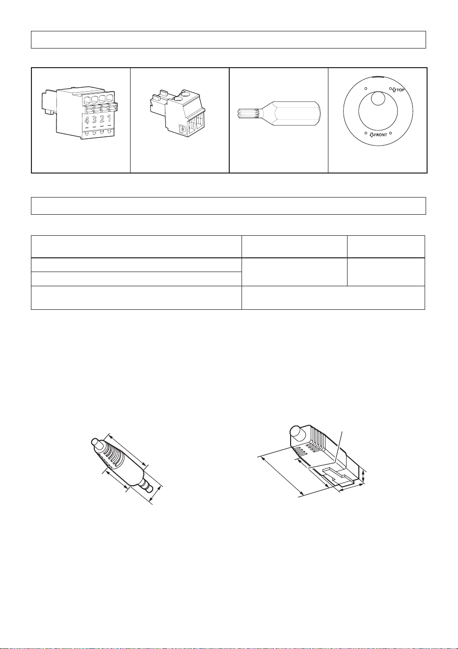
Standard accessories
Important Safety Instructions ............................. 1 pc.
EXT I/O terminal plug*
1
×1 Power cord plug
*1
×1
Bit (Hex wrench,
screw size 6.35 mm
{1/4 inches} T10) ×1 Template A ×1
*1 The power cord plug and EXT I/O terminal plug are attached to the camera.
Other items that are needed (not included)
• Mounting screws
Installation method
Recommended
screw*
1
Minimum pull-out
strength*
2
Mount the camera to a two-gangbox/junction box.
M4 x 16 mm*
3
{5/8 inches} x 2 pcs.
196 N {44 lbf}
Directly mount the camera onto the ceiling or wall.
Mount the camera using the exclusively designed
mount bracket.
Refer to the operating instructions of each
bracket.
*1 Select screws according to the material of the location that the camera will be mounted to. In this
case, wood screws and nails should not be used.
*2 This value indicates the minimum pull-out strength required value per screw. For information about
the minimum pull-out strength, refer to our technical information website <Control No.: C0120>.
*3 The screw length is an example when installing the camera on a robust ceiling or wall with a
thickness of 20 mm {25/32 inches} or more.
• Ethernet cable with RJ45 plug (category 5e or better, straight, 4 pairs (8 pins), less than 100 m {328feet})
• As necessary, audio input cable, audio output cable, alarm I/O cables, power supply cable
7
Straight section
17 mm {21/32 inches}
Diameter
9 mm {11/32 inches}
30 mm
{1-3/16 inches}
30 mm
{1-3/16 inches}
40 mm
{1-9/16 inches}
13 mm
{1/2 inches}
9 mm
{11/32 inches}
Straight section
Loading ...
Loading ...
Loading ...