Loading ...

Step 2
Preparations
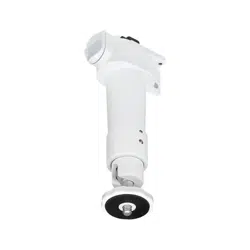
To x the indoor box type camera to this
product
To x other cameras to this product
【Common】 Temporary xing method of screws
Note:
• When tightening the screws, the surface of
this product may be scratched by screw
fixation, but this is not a problem with regard
to use of the product.
Step 3
Fixing the camera
1 Turn the hexagonal hole with a hexagonal wrench to
loosen the fixation of the movable part.
3 mm {1/8 inches} hexagon wrench(locally pro-
cured).
The following is an illustration of an indoor box type
camera as an example.
2 Attach the camera to the head portion of this product.
Step 4
Fixing to the lighting rail
1 Temporarily fix this product with the camera attached to the lighting rail. To remove this product
from the lighting rail, perform the ① to ④inreverseorder.
Temporarily fix the screws so that their
tips do not protrude beyond the
mounting surface of this product.
2 Tighten the two screws that were temporarily fixed and fix this product to the lighting rail.
Note:
• Please be careful not to overtighten the screws as this will damage the lighting rail.
• At this time, the lighting rail may be scratched by screw fixation.
Step 5
Adjusting the angle of view
1 With power connected to the camera, connect a monitor to the MONITOR OUT terminal to bring
up the screen. For models without a MONITOR OUT terminal, use a PC to connect the camera
to the network and display the shooting screen. Loosen the fixation of the movable part again by
referring to Step3-1.
2 Adjust camera orientation while watching the screen.
3 Turn the hexagonal hole with a hexagonal wrench to
tighten of the movable part of this product.
3 mm {1/8 inches} hexagon wrench (locally pro-
cured)
Recommended tightening torque: 0.39 N·m {0.29 lbf·ft}
After fixing this product to the lighting rail, be sure to check that the safety wire from
the camera is not in contact with the inside of the rail (energized part).
1 Pass the safety wire (camera accessory)
through the camera
2 Temporarily fix two screws (accessory) to this
product (tighten the safety wire from the
camera to one of the screws)
From the camera
safety wire
1 Temporarily fix two screws (accessory) to this
product.
2 Attach the safety wire (supplied with the
camera) to the product as shown below.
3 Secure the safety wire to the camera.
①
②
A
B
A
B
90°
Recommended tightening torque:
1.97 N·m {1.45 lbf·ft}
(Max. 2.95 N-m{2.18 lbf·ft})
OPEN
LOCK
Stopper
button
①
②
③
④
Safety wire
90°
360°
LOCK
60°60°
OPEN
LOCK LOCK
60°60°
Loading ...
Loading ...
