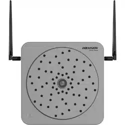

Acoustic Imager
User Manual

Acoustic Imager User Manual
i
Legal Information
About this Document
●
This Document includes instructions for using and managing the Product. Pictures, charts,
images and all other information hereinafter are for description and explanation only.
●
The information contained in the Document is subject to change, without notice, due to
firmware updates or other reasons. Please find the latest version of the Document at the
Hikvision website (https://www.hikvision.com). Unless otherwise agreed, Hangzhou Hikvision
Digital Technology Co., Ltd. or its affiliates (hereinafter referred to as "Hikvision") makes no
warranties, express or implied.
●
Please use the Document with the guidance and assistance of professionals trained in
supporting the Product.
About this Product
This product can only enjoy the after-sales service support in the country or region where the
purchase is made.
Acknowledgment of Intellectual Property Rights
●
Hikvision owns the copyrights and/or patents related to the technology embodied in the
Products described in this Document, which may include licenses obtained from third parties.
●
Any part of the Document, including text, pictures, graphics, etc., belongs to Hikvision. No part
of this Document may be excerpted, copied, translated, or modified in whole or in part by any
means without written permission.
●
and other Hikvision's trademarks and logos are the properties of Hikvision in
various jurisdictions.
●
Other trademarks and logos mentioned are the properties of their respective owners.
LEGAL DISCLAIMER
●
TO THE MAXIMUM EXTENT PERMITTED BY APPLICABLE LAW, THIS DOCUMENT AND THE
PRODUCT DESCRIBED, WITH ITS HARDWARE, SOFTWARE AND FIRMWARE, ARE PROVIDED "AS
IS" AND "WITH ALL FAULTS AND ERRORS". HIKVISION MAKES NO WARRANTIES, EXPRESS OR
IMPLIED, INCLUDING WITHOUT LIMITATION, MERCHANTABILITY, SATISFACTORY QUALITY, OR
FITNESS FOR A PARTICULAR PURPOSE. THE USE OF THE PRODUCT BY YOU IS AT YOUR OWN
RISK. IN NO EVENT WILL HIKVISION BE LIABLE TO YOU FOR ANY SPECIAL, CONSEQUENTIAL,
INCIDENTAL, OR INDIRECT DAMAGES, INCLUDING, AMONG OTHERS, DAMAGES FOR LOSS OF
BUSINESS PROFITS, BUSINESS INTERRUPTION, OR LOSS OF DATA, CORRUPTION OF SYSTEMS, OR
LOSS OF DOCUMENTATION, WHETHER BASED ON BREACH OF CONTRACT, TORT (INCLUDING
NEGLIGENCE), PRODUCT LIABILITY, OR OTHERWISE, IN CONNECTION WITH THE USE OF THE
PRODUCT, EVEN IF HIKVISION HAS BEEN ADVISED OF THE POSSIBILITY OF SUCH DAMAGES OR
LOSS.
●
YOU ACKNOWLEDGE THAT THE NATURE OF THE INTERNET PROVIDES FOR INHERENT SECURITY
RISKS, AND HIKVISION SHALL NOT TAKE ANY RESPONSIBILITIES FOR ABNORMAL OPERATION,

Acoustic Imager User Manual
ii
PRIVACY LEAKAGE OR OTHER DAMAGES RESULTING FROM CYBER-ATTACK, HACKER ATTACK,
VIRUS INFECTION, OR OTHER INTERNET SECURITY RISKS; HOWEVER, HIKVISION WILL PROVIDE
TIMELY TECHNICAL SUPPORT IF REQUIRED.
●
YOU AGREE TO USE THIS PRODUCT IN COMPLIANCE WITH ALL APPLICABLE LAWS, AND YOU ARE
SOLELY RESPONSIBLE FOR ENSURING THAT YOUR USE CONFORMS TO THE APPLICABLE LAW.
ESPECIALLY, YOU ARE RESPONSIBLE, FOR USING THIS PRODUCT IN A MANNER THAT DOES NOT
INFRINGE ON THE RIGHTS OF THIRD PARTIES, INCLUDING WITHOUT LIMITATION, RIGHTS OF
PUBLICITY, INTELLECTUAL PROPERTY RIGHTS, OR DATA PROTECTION AND OTHER PRIVACY
RIGHTS. YOU SHALL NOT USE THIS PRODUCT FOR ANY PROHIBITED END-USES, INCLUDING THE
DEVELOPMENT OR PRODUCTION OF WEAPONS OF MASS DESTRUCTION, THE DEVELOPMENT
OR PRODUCTION OF CHEMICAL OR BIOLOGICAL WEAPONS, ANY ACTIVITIES IN THE CONTEXT
RELATED TO ANY NUCLEAR EXPLOSIVE OR UNSAFE NUCLEAR FUEL-CYCLE, OR IN SUPPORT OF
HUMAN RIGHTS ABUSES.
●
IN THE EVENT OF ANY CONFLICTS BETWEEN THIS DOCUMENT AND THE APPLICABLE LAW, THE
LATTER PREVAILS.
© Hangzhou Hikvision Digital Technology Co., Ltd. All rights reserved.
Acoustic Imager User Manual
iii
Symbol Conventions
The symbols that may be found in this document are defined as follows.
Symbol Description
Danger
Indicates a hazardous situation which, if not avoided, will or could
result in death or serious injury.
Caution
Indicates a potentially hazardous situation which, if not avoided,
could result in equipment damage, data loss, performance
degradation, or unexpected results.
Note
Provides additional information to emphasize or supplement
important points of the main text.

Acoustic Imager User Manual
iv
Contents
Chapter 1 Intrduction ................................................................................................................. 1
Chapter 2 Device Activation and Accessing ................................................................................. 2
2.1 Activate the Device via SADP ............................................................................................... 2
2.2 Activate the Device via Browser .......................................................................................... 2
2.3 Login ..................................................................................................................................... 3
2.3.1 Plug-in Installation .................................................................................................... 3
2.3.2 Login .......................................................................................................................... 4
Chapter 3 Live View .................................................................................................................... 5
3.1 Live View Parameters .......................................................................................................... 5
3.1.1 Start and Stop Live View ........................................................................................... 5
3.1.2 Aspect Ratio .............................................................................................................. 5
3.1.3 Select the Third-Party Plug-in ................................................................................... 5
3.1.4 Start Digital Zoom ..................................................................................................... 5
3.1.5 Start Digital Zoom Full Screen .................................................................................. 6
3.2 Set General Settings ............................................................................................................. 6
3.3 Set Filtering Settings ............................................................................................................ 7
Chapter 4 Common Settings ........................................................................................................ 8
4.1 Video Settings ...................................................................................................................... 8
4.1.1 Stream Type .............................................................................................................. 8
4.1.2 Video Type................................................................................................................. 8
4.1.3 Resolution ................................................................................................................. 8
4.1.4 Bitrate Type and Max. Bitrate .................................................................................. 8
4.1.5 Video Quality ............................................................................................................ 9
4.1.6 Frame Rate ................................................................................................................ 9
4.1.7 Video Encoding .......................................................................................................... 9
4.1.8 Smoothing ............................................................................................................... 10
4.2 Display Settings .................................................................................................................. 10
4.2.1 Scene Mode ............................................................................................................. 10
4.2.2 Video Standard ........................................................................................................ 11

Acoustic Imager User Manual
v
4.3 OSD ..................................................................................................................................... 12
4.4 Time and Date .................................................................................................................... 12
Chapter 5 Video and Audio ....................................................................................................... 14
5.1 Video Settings .................................................................................................................... 14
5.1.1 Stream Type ............................................................................................................ 14
5.1.2 Video Type............................................................................................................... 14
5.1.3 Resolution ............................................................................................................... 14
5.1.4 Bitrate Type and Max. Bitrate ................................................................................ 14
5.1.5 Video Quality .......................................................................................................... 15
5.1.6 Frame Rate .............................................................................................................. 15
5.1.7 Video Encoding ........................................................................................................ 15
5.1.8 Smoothing ............................................................................................................... 16
5.2 Audio Settings .................................................................................................................... 16
5.3 Display Settings .................................................................................................................. 16
5.3.1 Scene Mode ............................................................................................................. 16
5.3.2 Video Standard ........................................................................................................ 18
5.4 OSD ..................................................................................................................................... 18
Chapter 6 Video Recording and Picture Capture ........................................................................ 19
6.1 Storage Settings ................................................................................................................. 19
6.1.1 Memory Card .......................................................................................................... 19
6.1.2 Set Cloud Storage .................................................................................................... 20
6.2 Video Recording ................................................................................................................. 21
6.2.1 Record Automatically ............................................................................................. 21
6.2.2 Record Manually ..................................................................................................... 22
6.2.3 Playback and Download Video ............................................................................... 22
6.3 Capture Configuration ....................................................................................................... 23
6.3.1 Capture Automatically ............................................................................................ 23
6.3.2 Capture Manually.................................................................................................... 24
6.3.3 View and Download Picture ................................................................................... 24
Chapter 7 Event and Alarm ....................................................................................................... 26
7.1 Set Video Tampering Alarm ............................................................................................... 26

Acoustic Imager User Manual
vi
7.2 Set Exception Alarm ........................................................................................................... 27
7.3 Set Audio Detection ........................................................................................................... 27
7.4 Set Microphone Exception ................................................................................................. 28
Chapter 8 Arming Schedule and Alarm Linkage ........................................................................... 1
8.1 Set Arming Schedule ............................................................................................................ 1
8.2 Linkage Method Settings ..................................................................................................... 2
8.2.1 Memory Card Uploading ........................................................................................... 2
8.2.2 Notify Surveillance Center ........................................................................................ 2
8.2.3 Trigger Recording ...................................................................................................... 2
8.2.4 Alarm Server .............................................................................................................. 2
Chapter 9 Network Settings ........................................................................................................ 3
9.1 TCP/IP ................................................................................................................................... 3
9.2 Set Wireless Dial .................................................................................................................. 4
9.3 Data Monitoring ................................................................................................................... 5
9.4 HTTP(S) ................................................................................................................................. 6
9.5 Multicast .............................................................................................................................. 7
9.5.1 Multicast Discovery ................................................................................................... 7
9.6 RTSP ...................................................................................................................................... 7
9.7 Port Mapping ....................................................................................................................... 8
9.7.1 Set Auto Port Mapping ............................................................................................. 8
9.7.2 Set Manual Port Mapping ......................................................................................... 8
9.7.3 Set Port Mapping on Router ..................................................................................... 9
9.8 Set ISUP .............................................................................................................................. 10
Chapter 10 System and Security ................................................................................................ 11
10.1 System Settings ................................................................................................................ 11
10.1.1 View Device Information ...................................................................................... 11
10.1.2 Time and Date ....................................................................................................... 11
10.1.3 Set RS-232 ............................................................................................................. 12
10.1.4 Set RS-485 ............................................................................................................. 12
10.1.5 eMMC Protection .................................................................................................. 13
10.2 User and Account ............................................................................................................. 13

Acoustic Imager User Manual
vii
10.2.1 Set User Account and Permission ......................................................................... 13
10.2.2 Simultaneous Login ............................................................................................... 14
10.2.3 Online Users .......................................................................................................... 14
10.2.4 Set Live View Connection ..................................................................................... 14
10.3 Maintenance .................................................................................................................... 15
10.3.1 Restart ................................................................................................................... 15
10.3.2 Upgrade ................................................................................................................. 15
10.3.3 Restore and Default .............................................................................................. 15
10.3.4 Import and Export Configuration File ................................................................... 16
10.3.5 Search and Manage Log ........................................................................................ 16
10.3.6 Search Security Audit Logs .................................................................................... 16
10.3.7 SSH ......................................................................................................................... 17
10.3.8 Export Diagnose Information ............................................................................... 17
10.4 Security ............................................................................................................................. 17
10.4.1 Set IP Address Filter .............................................................................................. 17
10.4.2 Control Timeout Settings ...................................................................................... 18
10.4.3 Certificate Management ....................................................................................... 18
10.4.4 TLS ......................................................................................................................... 21

Acoustic Imager User Manual
1
Chapter 1 Intrduction
Acoustic Imager (the device) is a sound wave detection product that detects the leakage of
pressurized air or local discharge in high-pressure systems in industrial environment, and images in
acoustic palette format to mark the sound source position.
Acoustic imager can be used in power transmission, substation, and power distribution in the
power industry, as well as in the detection of gas transmission pipes, tanks, and valves in the
petrochemical industry.

Acoustic Imager User Manual
2
Chapter 2 Device Activation and Accessing
To protect the security and privacy of the user account and data, you should set a login password
to activate the device when access the device via network.
Note
Refer to the user manual of the software client for the detailed information about the client
software activation.
2.1 Activate the Device via SADP
Search and activate the online devices via SADP software.
Before You Start
Access www.hikvision.com to get SADP software to install.
Steps
1. Connect the device to network using the network cable.
2. Run SADP software to search the online devices.
3. Check Device Status from the device list, and select Inactive device.
4. Create and input the new password in the password field, and confirm the password.
Caution
We highly recommend you create a strong password of your own choosing (using a minimum of
8 characters, including upper case letters, lower case letters, numbers, and special characters)
in order to increase the security of your product. And we recommend you reset your password
regularly, especially in the high security system, resetting the password monthly or weekly can
better protect your product.
5. Click OK.
Device Status changes into Active.
6. Optional: Change the network parameters of the device in Modify Network Parameters.
2.2 Activate the Device via Browser
You can access and activate the device via the browser.
Steps
1. Connect the device to the PC using the network cables.
2. Change the IP address of the PC and device to the same segment.

Acoustic Imager User Manual
3
Note
The default IP address of the device is 192.168.1.64. You can set the IP address of the PC from
192.168.1.2 to 192.168.1.253 (except 192.168.1.64). For example, you can set the IP address of
the PC to 192.168.1.100.
3. Input 192.168.1.64 in the browser.
4. Set device activation password.
Caution
We highly recommend you create a strong password of your own choosing (using a minimum of
8 characters, including at least three of the following categories: upper case letters, lower case
letters, numbers, and special characters) in order to increase the security of your product. And
we recommend you reset your password regularly, especially in the high security system,
resetting the password monthly or weekly can better protect your product.
5. Click OK.
6. Input the activation password to log in to the device.
7. Optional: Go to Configuration → Network → Network Settings → TCP/IP to change the IP
address of the device to the same segment of your network.
2.3 Login
Log in to the device via Web browser.
2.3.1 Plug-in Installation
Certain operation systems and web browser may restrict the display and operation of the device
function. You should install plug-in or complete certain settings to ensure normal display and
operation. For detailed restricted function, refer to the actual device.
Web Browser Operation
●
Google Chrome 70+
●
Mozilla Firefox 70+
●
Edge 89+
●
Safari 13+
Click to download and
install plug-in.

Acoustic Imager User Manual
4
2.3.2 Login
Steps
1. Enter the device IP address in the browser to display the login screen.
2. Enter user name and password. Click Login.
3. Optional:Use the auxiliary toolbar.
Click Enter keywords in the search box, and the device will display the
search results. Click the results to go to the function configuration
page.
Click It is used to view device help instructions, online documents, and
open source software instructions.
Click It is used to view the current login account information, and can be
used for password operation and logout.
Note
Account permission is required to change password.

Acoustic Imager User Manual
5
Chapter 3 Live View
It introduces the live view parameters, function icons and transmission parameters settings.
3.1 Live View Parameters
The supported functions vary depending on the model.
3.1.1 Start and Stop Live View
Click Live View. Click to start live view. Click to stop live view.
3.1.2 Aspect Ratio
Aspect Ratio is the display ratio of the width to height of the image.
●
refers to 4:3 window size.
●
refers to 16:9 window size.
●
refers to original window size.
●
refers to self-adaptive window size.
●
refers to original ratio window size.
3.1.3 Select the Third-Party Plug-in
When the live view cannot display via certain browsers, you can change the plug-in for live view
according to the browser.
Steps
1. Click Live View.
2. Click to select the plug-in.
3.1.4 Start Digital Zoom
It helps to see a detailed information of any region in the image.
Steps
1. Click to enable the digital zoom.
2. In live view image, drag the mouse to select the desired region.
3. Click in the live view image to back to the original image.

Acoustic Imager User Manual
6
3.1.5 Start Digital Zoom Full Screen
It is used to view the image in full screen.
Click to enable full screen, and press ESC to exit full screen.
3.2 Set General Settings
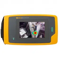
In different frequency bands, the position of the sound source in the scene is marked and located
in the form of acoustic palette, and the real-time sound intensity level of the sound source is
displayed.
Steps
1. Go to Live View → General Settings.
2. Select Sound Source Mode.
Single Sound Source Mode
The live view image will show only one frequency point which is the most powerful one.
Multiple Sound Source Mode
The live view image will show more than one frequency points which are the most
powerful frequency points.
3. Draw detection area.
1) Enable Enable .
2) Click Draw to draw an area in the live view.
3) Optional: Click Draw again to clear the selected area and draw again.
4. Set Max. Frequency and Min. Frequency. Locate the sound in the frequency range and display
the acoustic palette in the corresponding sound source position in the image.
Note
●
Adjusting frequency ranges from 5 to 72 KHz.
●
Frequency range (the difference between max. and min. frequency) is: 0.05 to 24 KHz.
5. Set acoustic palette.
Dynamic Range
Max. Decibel and Min. Decibel Difference. The larger the dynamic range, the larger the
acoustic palette.
Noise Threshold
It is a threshold for setting acoustic palette overlay on the live view image. If the value is
lower than the threshold, the data will be filtered. When the real-time sound intensity is no
greater than the threshold, the acoustic palette will not be overlaid.When the real-time
sound intensity is greater than the threshold, the acoustic palette will be overlaid.

Acoustic Imager User Manual
7
Opacity
The higher the opacity, the more obvious the acoustic palette. The lower the opacity of the
cloud image, the more obvious the image.
Palette Mode
Set the palette mode of the acoustic palette to improve the recognition of sound source
target details. The acoustic palette will display different colors based on changes in sound
intensity.
6. Click Save.
3.3 Set Filtering Settings
Real-time filtering is supported. You can collect the filtered sound signal in live view. The filtering
parameters affect live view sound and video sound, and do not affect acoustic palette localization.
Steps
1. Go to Live View →Filter Settings.
2. Select Sound Source Mode.
Single Sound Source Mode
The live view image will show only one frequency point which is the most powerful one.
Multiple Sound Source Mode
The live view image will show more than one frequency points which are the most
powerful frequency points.
3. Draw detection area.
1) Enable Enable .
2) Click Draw to draw an area in the live view.
3) Optional: Click Draw again to clear the selected area and draw again.
2. Enable the corresponding bandpass filtering according to actual needs.
Note
High-Pass and Low-Pass filtering can be enabled at the same time .
3. Set Filtering Order and Frequency Points.
Note
When enabling both high-pass and low-pass filtering, the low frequency point should be larger
than the high frequency point.
4. Click Save.

Acoustic Imager User Manual
8
Chapter 4 Common Settings
Go to setting page: Configuration → Common Settings to set video parameters, image
parameters, OSD parameters, and time parameters of the device.
4.1 Video Settings
This part introduces the settings of video parameters, such as, stream type, video encoding, and
resolution.
Go to setting page: Configuration → Video/Audio → Video.
4.1.1 Stream Type
For device supports more than one stream, you can specify parameters for each stream type.
Main Stream
The stream stands for the best stream performance the device supports. It usually offers the
best resolution and frame rate the device can do. But high resolution and frame rate usually
means larger storage space and higher bandwidth requirements in transmission.
4.1.2 Video Type
Select the content (video and audio) that should be contained in the stream.
Video Stream
Only video content is contained in the stream.
Video&Audio
Video content and audio content are contained in the composite stream.
4.1.3 Resolution
Select video resolution according to actual needs. Higher resolution requires higher bandwidth
and storage.
4.1.4 Bitrate Type and Max. Bitrate
Constant Bitrate
It means that the stream is compressed and transmitted at a comparatively fixed bitrate. The
compression speed is fast, but mosaic may occur on the image.

Acoustic Imager User Manual
9
Variable Bitrate
It means that the device automatically adjust the bitrate under the set Max. Bitrate. The
compression speed is slower than that of the constant bitrate. But it guarantees the image
quality of complex scenes.
4.1.5 Video Quality
When Bitrate Type is set as Variable, video quality is configurable. Select a video quality according
to actual needs. Note that higher video quality requires higher bandwidth.
4.1.6 Frame Rate
The frame rate is to describe the frequency at which the video stream is updated and it is
measured by frames per second (fps).
A higher frame rate is advantageous when there is movement in the video stream, as it maintains
image quality throughout. Note that higher frame rate requires higher bandwidth and larger
storage space.
4.1.7 Video Encoding
It stands for the compression standard the device adopts for video encoding.
Note
Available compression standards vary according to device models.
H.264
H.264, also known as MPEG-4 Part 10, Advanced Video Coding, is a compression standard.
Without compressing image quality, it increases compression ratio and reduces the size of video
file than MJPEG or MPEG-4 Part 2.
H.265
H.265, also known as High Efficiency Video Coding (HEVC) and MPEG-H Part 2, is a compression
standard. In comparison to H.264, it offers better video compression at the same resolution, frame
rate and image quality.
I-Frame Interval
I-frame interval defines the number of frames between 2 I-frames.
In H.264 and H.265, an I-frame, or intra frame, is a self-contained frame that can be independently
decoded without any reference to other images. An I-frame consumes more bits than other
frames. Thus, video with more I-frames, in other words, smaller I-frame interval, generates more

Acoustic Imager User Manual
10
steady and reliable data bits while requiring more storage space.
SVC
Scalable Video Coding (SVC) is the name for the Annex G extension of the H.264 or H.265 video
compression standard.
The objective of the SVC standardization has been to enable the encoding of a high-quality video
bitstream that contains one or more subset bitstreams that can themselves be decoded with a
complexity and reconstruction quality similar to that achieved using the existing H.264 or H.265
design with the same quantity of data as in the subset bitstream. The subset bitstream is derived
by dropping packets from the larger bitstream.
SVC enables forward compatibility for older hardware: the same bitstream can be consumed by
basic hardware which can only decode a low-resolution subset, while more advanced hardware
will be able decode high quality video stream.
4.1.8 Smoothing
It refers to the smoothness of the stream. The higher value of the smoothing is, the better fluency
of the stream will be, though, the video quality may not be so satisfactory. The lower value of the
smoothing is, the higher quality of the stream will be, though it may appear not fluent.
4.2 Display Settings
It offers the parameter settings to adjust image features.
Go to Configuration → Image → Display Settings.
Click Default to restore settings.
4.2.1 Scene Mode
There are several sets of image parameters predefined for different installation environments.
Select a scene according to the actual installation environment to speed up the display settings.
Image Adjustment
By adjusting the Brightness, Saturation, Contrast and Sharpness, the image can be best displayed.
Exposure Settings
Exposure is controlled by the combination of iris, shutter, and photo sensibility. You can adjust
image effect by setting exposure parameters.
In manual mode, you need to set Exposure Time, Gain and Slow Shutter.

Acoustic Imager User Manual
11
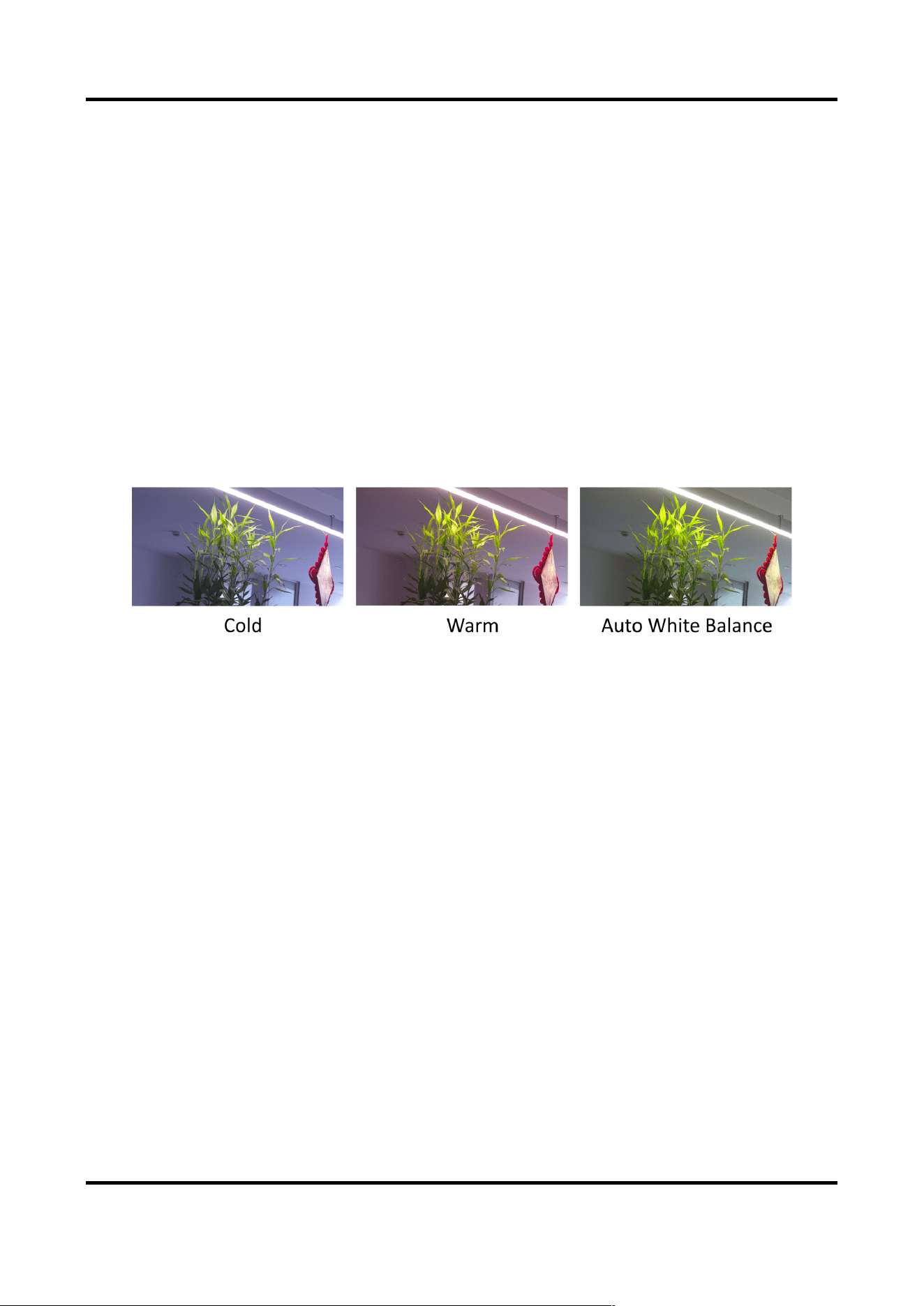
White Balance
White balance is the white rendition function of the device. It is used to adjust the color
temperature according to the environment.
Figure 4-1 White Balance
DNR
Digital Noise Reduction is used to reduce the image noise and improve the image quality. Normal
and Expert modes are selectable.
Normal
Set the DNR level to control the noise reduction degree. The higher level means stronger
reduction degree.
Figure 4-2 DNR
4.2.2 Video Standard
Video standard is an ability of a video card or video display device that defines the amount of
colors that are shown and the resolution. In PAL, 25 or 50 frames are transmitted each second.
Each frame is made up of 625 individual scan lines. Select video signal standard according to the

Acoustic Imager User Manual
12
video system in your country/region.
4.3 OSD
You can customize OSD (On-screen Display) information such as device name, time/date, font,
color, and text overlay displayed on video stream.
Go to OSD setting page: Configuration → Image → OSD Settings. Set the corresponding
parameters, and click Save to take effect.
Display
Set device name, date, week, and their related display formats. For certain device models, you can
also set tilt angle as the displayed information.
Format Settings
Set OSD parameters, such as Display Mode, OSD Size, Font Color, and Alignment.
Text Overlay
Set customized overlay text on image.
4.4 Time and Date
You can configure time and date of the device by configuring time zone, time synchronization and
Daylight Saving Time (DST).
Synchronize Time Manually
Steps
1. Go to Configuration → System → System Settings → Time Settings.
2. Select Time Zone.
3. Select Manual Time Sync..
4. Choose one time synchronization method.
–
Select Set Time, and manually input or select date and time from the pop-up calendar.
Click Sync. with computer time to synchronize the time of the device with that of the local PC.
5. Click Save.
Set NTP Server
You can use NTP server when accurate and reliable time source is required.
Before You Start
Set up a NTP server or obtain NTP server information.

Acoustic Imager User Manual
13
Steps
1. Go to Configuration → System → System Settings → Time Settings.
2. Select Time Zone.
3. Click NTP.
4. Set Server Address, NTP Port and Interval.
Note
Server Address is NTP server IP address.
5. Click Test to test server connection.
6. Click Save.
Set DST
If the region where the device is located adopts Daylight Saving Time (DST), you can set this
function.
Steps
1. Go to Configuration → System → System Settings → Time Settings.
2. Check Enable.
3. Select Start Time, End Time and DST Bias.
4. Click Save.

Acoustic Imager User Manual
14
Chapter 5 Video and Audio
This part introduces the configuration of video and audio related parameters.
5.1 Video Settings
This part introduces the settings of video parameters, such as, stream type, video encoding, and
resolution.
Go to setting page: Configuration → Video/Audio → Video.
5.1.1 Stream Type
For device supports more than one stream, you can specify parameters for each stream type.
Main Stream
The stream stands for the best stream performance the device supports. It usually offers the
best resolution and frame rate the device can do. But high resolution and frame rate usually
means larger storage space and higher bandwidth requirements in transmission.
5.1.2 Video Type
Select the content (video and audio) that should be contained in the stream.
Video Stream
Only video content is contained in the stream.
Video&Audio
Video content and audio content are contained in the composite stream.
5.1.3 Resolution
Select video resolution according to actual needs. Higher resolution requires higher bandwidth
and storage.
5.1.4 Bitrate Type and Max. Bitrate
Constant Bitrate
It means that the stream is compressed and transmitted at a comparatively fixed bitrate. The
compression speed is fast, but mosaic may occur on the image.

Acoustic Imager User Manual
15
Variable Bitrate
It means that the device automatically adjust the bitrate under the set Max. Bitrate. The
compression speed is slower than that of the constant bitrate. But it guarantees the image
quality of complex scenes.
5.1.5 Video Quality
When Bitrate Type is set as Variable, video quality is configurable. Select a video quality according
to actual needs. Note that higher video quality requires higher bandwidth.
5.1.6 Frame Rate
The frame rate is to describe the frequency at which the video stream is updated and it is
measured by frames per second (fps).
A higher frame rate is advantageous when there is movement in the video stream, as it maintains
image quality throughout. Note that higher frame rate requires higher bandwidth and larger
storage space.
5.1.7 Video Encoding
It stands for the compression standard the device adopts for video encoding.
Note
Available compression standards vary according to device models.
H.264
H.264, also known as MPEG-4 Part 10, Advanced Video Coding, is a compression standard.
Without compressing image quality, it increases compression ratio and reduces the size of video
file than MJPEG or MPEG-4 Part 2.
H.265
H.265, also known as High Efficiency Video Coding (HEVC) and MPEG-H Part 2, is a compression
standard. In comparison to H.264, it offers better video compression at the same resolution, frame
rate and image quality.
I-Frame Interval
I-frame interval defines the number of frames between 2 I-frames.
In H.264 and H.265, an I-frame, or intra frame, is a self-contained frame that can be independently
decoded without any reference to other images. An I-frame consumes more bits than other
frames. Thus, video with more I-frames, in other words, smaller I-frame interval, generates more

Acoustic Imager User Manual
16
steady and reliable data bits while requiring more storage space.
SVC
Scalable Video Coding (SVC) is the name for the Annex G extension of the H.264 or H.265 video
compression standard.
The objective of the SVC standardization has been to enable the encoding of a high-quality video
bitstream that contains one or more subset bitstreams that can themselves be decoded with a
complexity and reconstruction quality similar to that achieved using the existing H.264 or H.265
design with the same quantity of data as in the subset bitstream. The subset bitstream is derived
by dropping packets from the larger bitstream.
SVC enables forward compatibility for older hardware: the same bitstream can be consumed by
basic hardware which can only decode a low-resolution subset, while more advanced hardware
will be able decode high quality video stream.
5.1.8 Smoothing
It refers to the smoothness of the stream. The higher value of the smoothing is, the better fluency
of the stream will be, though, the video quality may not be so satisfactory. The lower value of the
smoothing is, the higher quality of the stream will be, though it may appear not fluent.
5.2 Audio Settings
It is a function to set audio parameters such as audio encoding.
Go to the audio settings page: Configuration → Video/Audio → Audio.
Note
Only certain models support the function.
5.3 Display Settings
It offers the parameter settings to adjust image features.
Go to Configuration → Image → Display Settings.
Click Default to restore settings.
5.3.1 Scene Mode
There are several sets of image parameters predefined for different installation environments.
Acoustic Imager User Manual
17
Select a scene according to the actual installation environment to speed up the display settings.
Image Adjustment
By adjusting the Brightness, Saturation, Contrast and Sharpness, the image can be best displayed.
Exposure Settings
Exposure is controlled by the combination of iris, shutter, and photo sensibility. You can adjust
image effect by setting exposure parameters.
In manual mode, you need to set Exposure Time, Gain and Slow Shutter.
White Balance
White balance is the white rendition function of the device. It is used to adjust the color
temperature according to the environment.
Figure 5-1 White Balance
DNR
Digital Noise Reduction is used to reduce the image noise and improve the image quality. Normal
and Expert modes are selectable.
Normal
Set the DNR level to control the noise reduction degree. The higher level means stronger
reduction degree.

Acoustic Imager User Manual
18
Figure 5-2 DNR
5.3.2 Video Standard
Video standard is an ability of a video card or video display device that defines the amount of
colors that are shown and the resolution. In PAL, 25 or 50 frames are transmitted each second.
Each frame is made up of 625 individual scan lines. Select video signal standard according to the
video system in your country/region.
5.4 OSD
You can customize OSD (On-screen Display) information such as device name, time/date, font,
color, and text overlay displayed on video stream.
Go to OSD setting page: Configuration → Image → OSD Settings. Set the corresponding
parameters, and click Save to take effect.
Display
Set device name, date, week, and their related display formats. For certain device models, you can
also set tilt angle as the displayed information.
Format Settings
Set OSD parameters, such as Display Mode, OSD Size, Font Color, and Alignment.
Text Overlay
Set customized overlay text on image.

Acoustic Imager User Manual
19
Chapter 6 Video Recording and Picture Capture
This part introduces the operations of capturing video clips and snapshots, playback, and
downloading captured files.
6.1 Storage Settings
This part introduces the configuration of several common storage paths.
6.1.1 Memory Card
You can view the capacity, free space, status, type, and property of the memory card. Encryption
of memory card is supported to ensure data security.
Set New or Unencrypted Memory Card
Before You Start
Insert a new or unencrypted memory card to the device. For detailed installation, refer to Quick
Start Guide of the device.
Steps
1. Go to Configuration → Storage → Storage Management → HDD Management.
2. Select the memory card.
Note
If an Unlock button appears, you need to unlock the memory card first. See Detect Memory
Card Status for details.
3. Click Format to initialize the memory card.
When the Status of memory card turns from Uninitialized to Normal, the memory card is ready
for use.
4. Optional: Encrypt the memory card.
1) Click Encrypted Format.
2) Set the encryption password.
3) Click OK.
When the Encryption Status turns to Encrypted, the memory card is ready for use.
Note
Keep your encryption password properly. Encryption password cannot be found if forgotten.

Acoustic Imager User Manual
20
5. Optional: Define the Quota of the memory card. Input the percentage for storing different
contents according to your needs.
6. Click Save.
Set Encrypted Memory Card
Before You Start
●
Insert an encrypted memory card to the device. For detailed installation, refer to Quick Start
Guide of the device.
●
You need to know the correct encryption password of the memory card.
Steps
1. Go to Configuration → Storage → Storage Management → HDD Management.
2. Select the memory card.
3. Verify the encryption password.
1) Click Parity.
2) Enter the encryption password.
3) Click OK.
When the Encryption Status turns to Encrypted, the memory card is ready for use.
Note
If the encryption password is forgotten and you still want to use this memory card, see Set New
or Unencrypted Memory Card to format and set the memory card. All existing contents will be
removed.
4. Optional: Define the Quota of the memory card. Input the percentage for storing different
contents according to your needs.
5. Click Save.
6.1.2 Set Cloud Storage
It helps to upload the captured pictures and data to the cloud. The platform requests picture
directly from the cloud for picture and analysis. The function is only supported by certain models.
Steps
Caution
If the cloud storage is enabled, the pictures are stored in the cloud video manager firstly.
1. Go to Configuration → Storage → Storage Management → Cloud Storage.
2. Check Enable.
3. Set basic parameters.
Protocol Version The protocol version of the cloud video manager.

Acoustic Imager User Manual
21
Server IP The IP address of the cloud video manager. It supports IPv4 address.
Serve Port The port of the cloud video manager. You are recommended to use
the default port.
AccessKey The key to log in to the cloud video manager.
SecretKey The key to encrypt the data stored in the cloud video manager.
User Name and
Password
The user name and password of the cloud video manager.
Picture Storage Pool
ID
The ID of the picture storage region in the cloud video manager.
Make sure storage pool ID and the storage region ID are the same.
4. Click Test to test the configured settings.
5. Click Save.
6.2 Video Recording
This part introduces the operations of manual and scheduled recording, playback, and
downloading recorded files.
6.2.1 Record Automatically
This function can record video automatically during configured time periods.
Before You Start
Select Trigger Recording in event settings for each record type except Continuous. See Event and
Alarm for details.
Steps
1. Go to Configuration → Storage → Schedule Settings → Record Schedule.
2. Check Enable.
3. Select a record type.
Note
The record type is vary according to different models.
Continuous
The video will be recorded continuously according to the schedule.
Event
The video is recorded when configured event is detected.

Acoustic Imager User Manual
22
4. Set schedule for the selected record type. Refer to Set Arming Schedule for the setting
operation.
5. Set the advanced recording parameters.
Overwrite
Enable Overwrite to overwrite the video records when the storage space is full. Otherwise
the device cannot record new videos.
Pre-record
The time period you set to record before the scheduled time.
Stream Type
Select the stream type for recording.
Note
When you select the stream type with higher bitrate, the actual time of the pre-record and
post-record may be less than the set value.
Record Delay
The time to delay recording when the event or alarm ends.
6. Click Save.
6.2.2 Record Manually
Steps
1. Go to Configuration → Local.
2. Set the Video Size and Video Saving Path for recorded video files.
3. Click Save.
4. Click in the live view interface to start recording. Click to stop recording.
What to do next
View the recorded video files.
Go to Configuration → Local and click Open behind Video Saving Path to open the saving path
and view the files.
6.2.3 Playback and Download Video
You can search, playback, clip and download the videos stored in the local storage or network
storage.
Steps
1. Go to Playback → Video.
2. Set search condition and click Search.
The matched video files showed on the timing bar.

Acoustic Imager User Manual
23
3. Click to play the video files.
–
Click to play video files in full screen. Press ESC to exit full screen.
–
Click to stop video playback for all channels.
4. Optional: Click to clip video files. Click again to stop clipping video files
Note
Go to Configuration → Local → Clip Saving Path, view and change the saving path of clipped
video files.
5. Optional: Click on the playback interface to download files.
Note
Go to Configuration → Local → Downloaded File Saving Path, view and change the saving path
of downloaded video files.
6.3 Capture Configuration
The device can capture the pictures manually or automatically and save them in configured saving
path. You can view and download the snapshots.
6.3.1 Capture Automatically
This function can capture pictures automatically during configured time periods.
Steps
1. Go to Configuration → Storage → Schedule Settings → Capture.
2. Set capture schedule. Refer to Set Arming Schedule for configuring schedule time.

Acoustic Imager User Manual
24
Figure 6-1 Set Capture Schedule
3. Set the capture type.
Scheduled
Capture a picture at the configured time interval.
4. Set the Format, Resolution, Quality, Interval, and Capture Number.
Note
The resolution of the captured picture is the same as the resolution of the captured picture
stream. You can select Stream Type in Advanced.
5. Click Save.
6.3.2 Capture Manually
Steps
1. Go to Configuration → Local.
2. Set the Image Format and saving path to for snapshots.
JPEG
The picture size of this format is comparatively small, which is better for network
transmission.
BMP
The picture is compressed with good quality.
3. Click Save.
4. Click near the live view or play back window to capture a picture manually.
6.3.3 View and Download Picture
You can search, view and download the pictures stored in the local storage or network storage.
Steps
1. Go to Playback → Picture.
2. Set search condition and click Search.
The matched pictures showed in the file list.
3. Download the pictures.

Acoustic Imager User Manual
25
–
Select the pictures then click Download to download them.
–
Click Download This Page to download the pictures of this page.
–
Click Download All to download all the pictures.
Note
Go to Configuration → Local → Playback Capture Saving Path, view and change the saving path
of captured pictures when playback.

Acoustic Imager User Manual
26
Chapter 7 Event and Alarm
This part introduces the configuration of events. The device takes certain response to triggered
alarm. Certain events may not be supported by certain device models.
7.1 Set Video Tampering Alarm
When the configured area is covered and cannot be monitored normally, the alarm is triggered
and the device takes certain alarm response actions.
Steps
1. Go to Configuration → Event → Event and Detection → Video Tampering.
2. Check Enable.
3. Set the Sensitivity. The higher the value is, the easier to detect the area covering.
4. Click and drag the mouse in the live view to draw the area.
Figure 7-1 Set Video Tampering Area

Acoustic Imager User Manual
27
5. Optional: Click to delete all the drawn areas.
6. Refer to Set Arming Schedule for setting scheduled time. Refer to Linkage Method Settings for
setting linkage method.
7. Click Save.
7.2 Set Exception Alarm
Exception such as network disconnection can trigger the device to take corresponding action.
Steps
1. Go to Configuration → Event → Event and Detection → Exception.
2. Select Exception Type.
HDD Full
The HDD storage is full.
HDD Error
Error occurs in HDD.
Network Disconnected
The device is offline.
IP Address Conflicted
The IP address of current device is same as that of other device in the network.
Illegal Login
Incorrect user name or password is entered.
3. Refer to Linkage Method Settings for setting linkage method.
4. Click Save.
7.3 Set Audio Detection
Check if the audio of the device is normal. If it is abnormal, the device can take linkage actions.
Steps
1. Go to Configuration → Event → Event and Detection → Audio Detection.
2. Select one or several audio detection types.
Enable Decibel Threshold Detection
If the decibel is larger than the set decibel threshold and exceeds the set duration, the alarm
will be triggered.
Enable Frequency Threshold Detection
If the decibel is larger than the set frequency threshold and exceeds the set duration, the
alarm will be triggered.
Enable Sound Source Localization Detection

Acoustic Imager User Manual
28
When there is acoustic palette in the image, the alarm will be triggered.
3. Refer to Set Arming Schedule for setting scheduled time. Refer to Linkage Method Settings for
setting linkage methods.
4. Click Save.
Note
The function is only supported by certain models. The actual function varies according to
different models.
7.4 Set Microphone Exception
Check if the microphone of the device is normal. If it is abnormal, the device can take linkage
actions.
Steps
1. Go to Configuration → Event → Event and Detection →Microphone Exception.
2. Select Detection Mode.
Auto Detection
The detection will be triggered automatically according to the auto detection interval.
Manual Detection
After you click Detect, one detection will be executed immediately, and the detection result
updated to the latest.
3. For the linkage method settings, refer to Linkage Method Settings.
4. Click Save.
Note
The function is only supported by certain models. The actual display varies with models.
Acoustic Imager User Manual
1
Chapter 8 Arming Schedule and Alarm Linkage
Arming schedule is a customized time period in which the device performs certain tasks. Alarm
linkage is the response to the detected certain incident or target during the scheduled time.
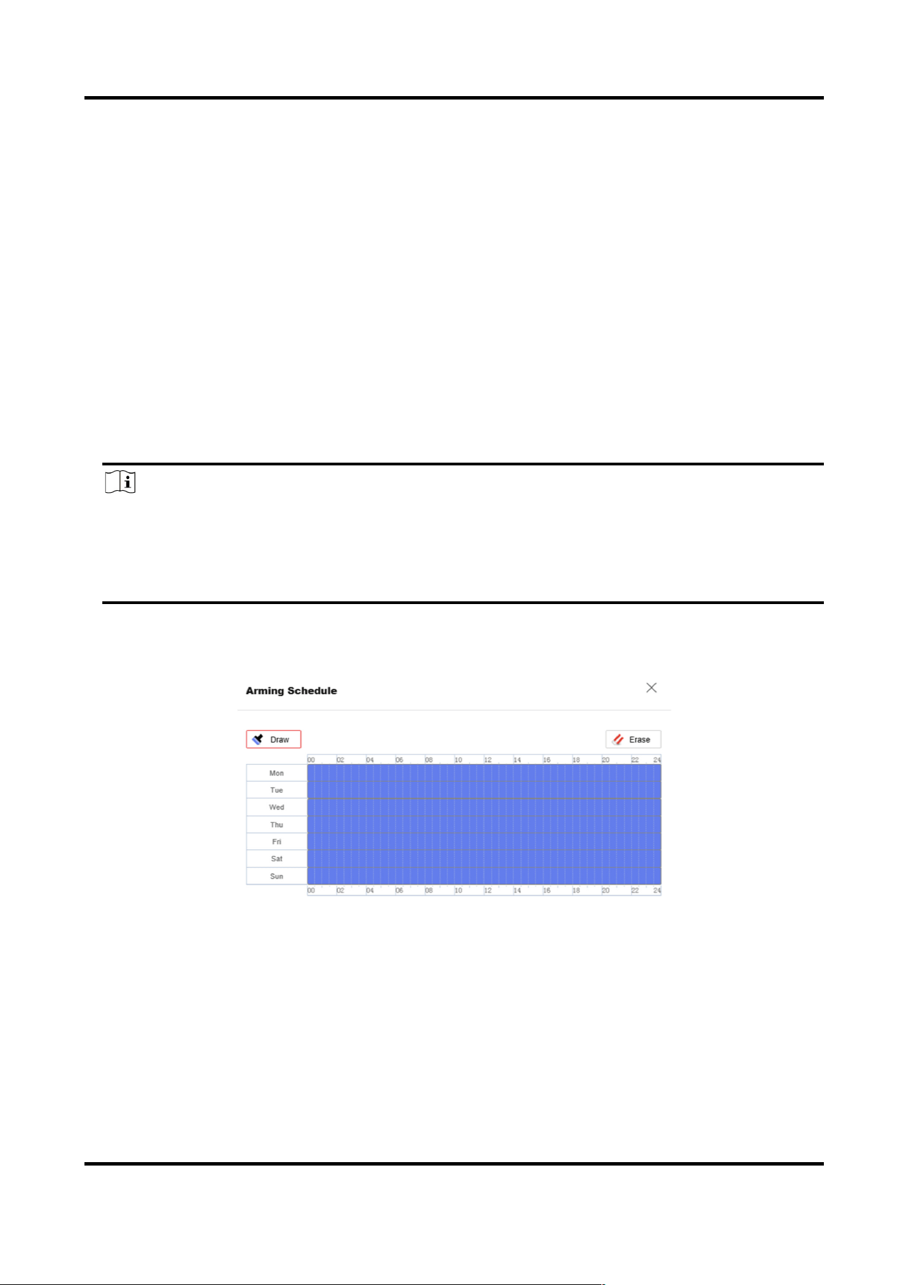
8.1 Set Arming Schedule
Set the valid time of the device tasks.
Steps
1. Optional: Click Arming Schedule and Linkage Method in the related event interface.
2. Click Edit behind Arming Schedule.
3. Click Draw, and drag the time bar to draw desired valid time.
Note
●
Each cell represents 30 minutes.
●
Move the mouse over the drawn time period to see specific time periods and fine-tune the
start time and end time.
●
Up to 8 periods can be configured for one day.
4. Click Erase, and drag the time bar to clear selected valid time.
5. Click OK to save the settings.
Figure 8-1 Set Arming Schedule

Acoustic Imager User Manual
2
8.2 Linkage Method Settings
You can enable the linkage functions when an event or alarm occurs.
8.2.1 Memory Card Uploading
If you have enabled and configured the memory card uploading, the device sends the alarm
information to the memory card when an alarm is triggered.
Refer to Set New or Unencrypted Memory Card for memory card storage configuration.
8.2.2 Notify Surveillance Center
Check Notify Surveillance Center, the alarm information is uploaded to the surveillance center
when an alarm event is detected.
8.2.3 Trigger Recording
Check Trigger Recording, and the device records the video about the detected alarm event.
For recording settings, refer to Video Recording and Picture Capture.
8.2.4 Alarm Server
The device can send alarms to destination IP address or host name through HTTP, HTTPS, or ISUP
protocol. The destination IP address or host name should support HTTP, HTTP, or ISUP data
transmission.
Set Alarm Server
Steps
1. Go to Configuration → Event → Alarm Setting → Alarm Server.
2. Enter Destination IP or Host Name, URL, and Port.
3. Select Protocol.
Note
HTTP, HTTPS, and ISUP are selectable. It is recommended to use HTTPS, as it encrypts the data
transmission during communication.
4. Click Test to check if the IP or host is available.
5. Click Save.

Acoustic Imager User Manual
3
Chapter 9 Network Settings
9.1 TCP/IP
TCP/IP settings must be properly configured before you operate the device over network. IPv4 and
IPv6 are both supported. Both versions can be configured simultaneously without conflicting to
each other.
Go to Configuration → Network → Network Settings → TCP/IP for parameter settings.
NIC Type
Select a NIC (Network Interface Card) type according to your network condition.
IPv4
Two IPv4 modes are available.
DHCP
The device automatically gets the IPv4 parameters from the network if you check DHCP. The
device IP address is changed after enabling the function. You can use SADP to get the device
IP address.
Note
The network that the device is connected to should support DHCP (Dynamic Host
Configuration Protocol).
Manual
You can set the device IPv4 parameters manually. Input IPv4 Address, IPv4 Subnet Mask, and
IPv4 Default Gateway, and click Test to see if the IP address is available.
IPv6
Three IPv6 modes are available.
Route Advertisement
The IPv6 address is generated by combining the route advertisement and the device Mac
address.
Note
Route advertisement mode requires the support from the router that the device is connected
to.
DHCP
The IPv6 address is assigned by the server, router, or gateway.

Acoustic Imager User Manual
4
Manual
Input IPv6 Address, IPv6 Subnet, IPv6 Default Gateway. Consult the network administrator
for required information.
MTU
It stands for maximum transmission unit. It is the size of the largest protocol data unit that can
be communicated in a single network layer transaction.
The valid value range of MTU is 1280 to 1500.
DNS
It stands for domain name server. It is required if you need to visit the device with domain
name. And it is also required for some applications (e.g., sending email). Set Preferred DNS
Server and Alternate DNS server properly if needed.
Domain Name Settings
Check Enable Dynamic Domain Name and input Register Domain Name. The device is
registered under the register domain name for easier management within the local area
network.
Note
DHCP should be enabled for the dynamic domain name to take effect.
9.2 Set Wireless Dial
The wireless network is provided with the mobile telecommunications technology via the 3G/4G
SIM card. For devices equipped with 3G/4G SIM card, the data stream of audio, video and image
can be transferred via 3G/4G wireless network.
Note
The wireless dial function is only supported by certain models.
Before You Start
Install a 3G/4G SIM card on the device to realize the wireless communication function.
Steps
1. Go to Configuration → Network → Network Settings → Wireless Dial.
2. Set dial-up parameters and save.
Dial Mode
Auto
Set the Dial Plan for dialing.
Manual
Click Connect to dial up, disconnect at the set offline time, or disconnect manually.

Acoustic Imager User Manual
5
Network Mode
Auto
The device will automatically switch mobile communication type according to signal
strength.
4G
4G is connected to the network, and 4G is faster than 3G to transmit audio, video, and
image data.
3G
Connect to network via 3G.
Phone
It is used to enter the corresponding number of the current SIM card.
MTU
It is used to set the max. transmission unit. It refers to the size of the max. data
package in network transmission.
Note
●
The supported mobile communication type is dependent on models.
●
Private network parameters should be configured by the operator. Configuration is not
required.
Verification Protocol
Auto, CHAP, and PAP are selectable. Auto is recommended.
9.3 Data Monitoring
You can view and manage the SIM card data or wired network data used by the device. SIM card
data is the data service provided by network carriers; wired network data is usually provided
through a 4G router.
Steps
3. Go to Configuration → Network → Network Settings → Data Monitoring.
4. Check Enable.
5. Set the following parameters according to your data plan.
Plan Type
Daily, Monthly, or Annually can be selected.
Data Plan
Enter the amount of usable data and select the unit.
Pre-Alarm Threshold

Acoustic Imager User Manual
6
When the used data reaches the set percentage of data plan, the device sends an alarm
message, and shows notification on the OSD or pop-up window.
6. Select Normal Linkage.
If Send Email or Notify Surveillance Center is selected, the device sends an alarm message by
Email or to surveillance center when the used data reaches the threshold.
7. Click Save.
Note
The function varies with different device models.
8.
9.4 HTTP(S)
HTTP is an application-layer protocol for transmitting hypermedia documents. HTTPS is a network
protocol that enables encrypted transmission and identity authentication, which improves the
security of remote access.
Steps
1. Go to Configuration → Network → Network Service → HTTP(S).
2. Enter HTTP Port.
Note
It refers to the port through which the browser accesses the device. For example, when the
HTTP Port is modified to 81, you need to enter http://192.168.1.64:81 in the browser for login.
3. Check Enable in HTTPS.
Note
You can click TLS Settings to set the TLS version that the device supports. Refer to for details.
4. Enter HTTPS Port.
5. Optional: Check HTTPS Browsing to access the device only via HTTPS protocol.
6. Select Server Certificate.
7. Set Web Authentication.
Authentication
Digest and digest/basic are supported, which means authentication information is needed
when WEB request is sent to the device. If you select digest/basic, it means the device
supports digest or basic authentication. If you select digest, the device only supports digest
authentication.
Digest Algorithm
MD5, SHA256 and MD5/SHA256 encrypted algorithm in WEB authentication. If you enable

Acoustic Imager User Manual
7
the digest algorithm except for MD5, the third-party platform might not be able to log in to
the device or enable live view because of compatibility. The encrypted algorithm with high
strength is recommended.
8. Click Save.
9.5 Multicast
Multicast is group communication where data transmission is addressed to a group of destination
devices simultaneously.
Go to Configuration → Network → Network Service → Multicast for the multicast settings.
IP Address
It stands for the address of multicast host.
9.5.1 Multicast Discovery
Go to Configuration → Network → Network Settings → TCP/IP to enable this function.
Check the Enable Multicast Discovery, and then the online network device can be automatically
detected by client software via private multicast protocol in the LAN.
9.6 RTSP
RTSP (Real Time Streaming Protocol) is an application-layer controlling protocol for streaming
media.
Steps
1. Go to Configuration → Network → Network Service → RTSP.
2. Enter Port.
3. Set Multicast parameters.
Stream Type
The stream type as the multicast source.
Video Port
The video port of the selected stream.
Audio Port
The audio port of the selected stream.
4. Set RTSP Authentication.
Authentication
Digest and digest/basic are supported, which means authentication information is needed
when RTSP request is sent to the device. If you select digest/basic, it means the device

Acoustic Imager User Manual
8
supports digest or basic authentication. If you select digest, the device only supports digest
authentication.
Digest Algorithm
MD5, SHA256 and MD5/SHA256 encrypted algorithm in RTSP authentication. If you enable
the digest algorithm except for MD5, the third-party platform might not be able to log in to
the device or enable live view because of compatibility. The encrypted algorithm with high
strength is recommended.
5. Click Save.
9.7 Port Mapping
By setting port mapping, you can access devices through the specified port.
Steps
1. Go to Configuration → Network → Network Service → NAT.
2. Select the port mapping mode.
Auto Port Mapping Refer to Set Auto Port Mapping for detailed information.
Manual Port
Mapping
Refer to Set Manual Port Mapping for detailed information.
3. Click Save.
9.7.1 Set Auto Port Mapping
Steps
1. Check Enable UPnP™, and choose a friendly name for the device, or you can use the default
name.
2. Select the port mapping mode to Auto.
3. Click Save.
Note
UPnP™ function on the router should be enabled at the same time.
9.7.2 Set Manual Port Mapping
Steps
1. Check Enable UPnP™, and choose a friendly name for the device, or you can use the default
name.
Acoustic Imager User Manual
9
2. Select the port mapping mode to Manual, and set the external port to be the same as the
internal port.
3. Click Save.
What to do next
Go to the router port mapping settings interface and set the port number and IP address to be the
same as those on the device. For more information, refer to the router user manual.
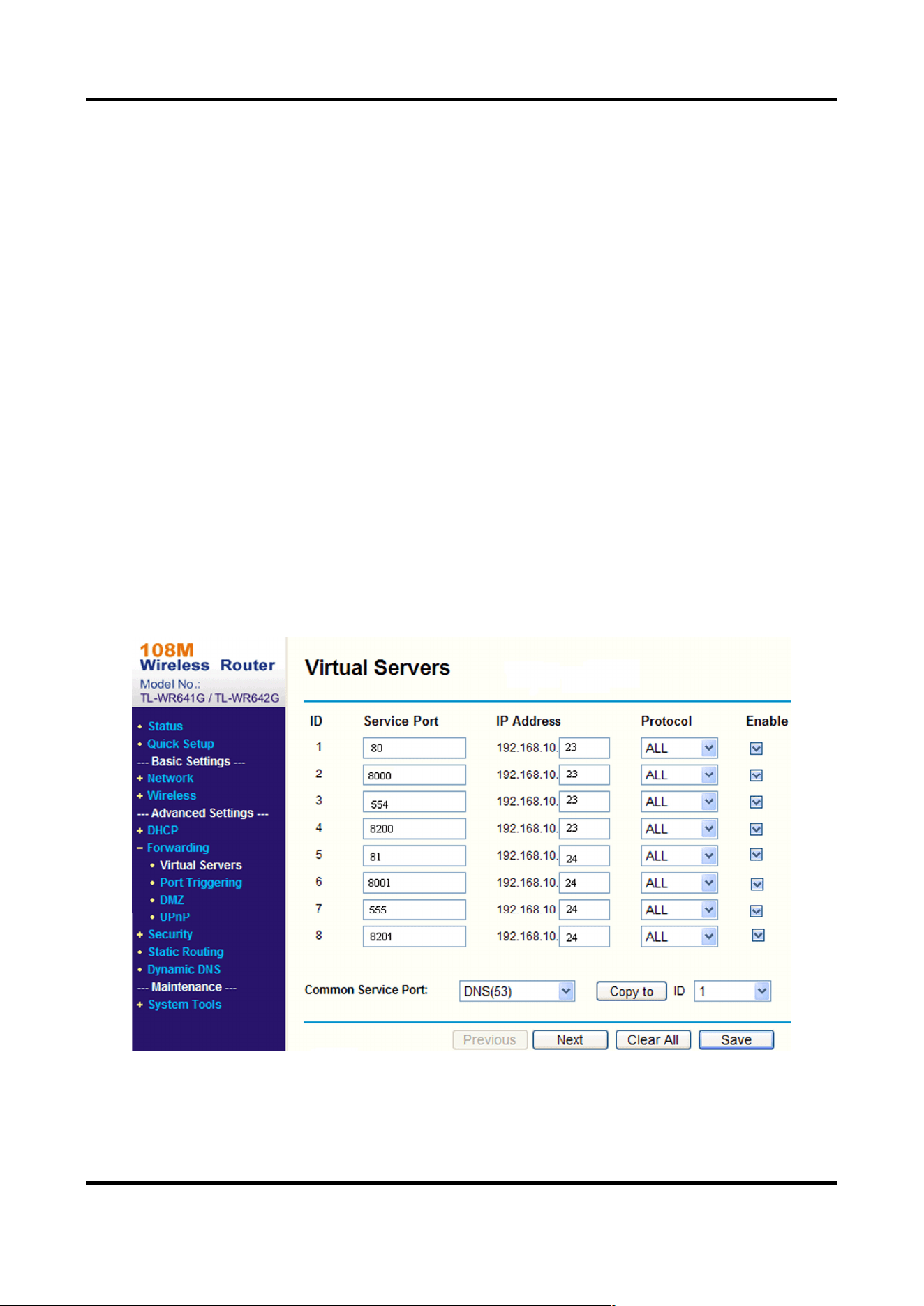
9.7.3 Set Port Mapping on Router
The following settings are for a certain router. The settings vary depending on different models of
routers.
Steps
1. Select the WAN Connection Type.
2. Set the IP Address, Subnet Mask and other network parameters of the router.
3. Go to Forwarding → Virtual Severs, and input the Port Number and IP Address.
4. Click Save.
Example
When the devices are connected to the same router, you can configure the ports of a device as 80,
8000, and 554 with IP address 192.168.1.23, and the ports of another device as 81, 8001, 555,
8201 with IP 192.168.1.24.
Figure 9-1 Port Mapping on Router

Acoustic Imager User Manual
10
Note
The port of the network device cannot conflict with other ports. For example, some web
management port of the router is 80. Change the device port if it is the same as the management
port.
9.8 Set ISUP
When the device is registered on ISUP platform (formerly called Ehome), you can visit and manage
the device, transmit data, and forward alarm information over public network.
Steps
1. Go to Configuration → Network → Platform Access → ISUP.
2. Optional: Select an access center.
3. Check Enable.
4. Select a protocol version and enter related parameters.
5. Click Save.
Register status turns to Online when the function is correctly set.

Acoustic Imager User Manual
11
Chapter 10 System and Security
It introduces system maintenance, system settings and security management, and explains how to
configure relevant parameters.
10.1 System Settings
10.1.1 View Device Information
You can view device information, such as Device No., Model, Serial No. and Firmware Version.
Enter Configuration → System → System Settings → Basic Information to view the device
information.
10.1.2 Time and Date
You can configure time and date of the device by configuring time zone, time synchronization and
Daylight Saving Time (DST).
Synchronize Time Manually
Steps
1. Go to Configuration → System → System Settings → Time Settings.
2. Select Time Zone.
3. Select Manual Time Sync..
4. Choose one time synchronization method.
–
Select Set Time, and manually input or select date and time from the pop-up calendar.
Click Sync. with computer time to synchronize the time of the device with that of the local PC.
5. Click Save.
Set NTP Server
You can use NTP server when accurate and reliable time source is required.
Before You Start
Set up a NTP server or obtain NTP server information.
Steps
1. Go to Configuration → System → System Settings → Time Settings.
2. Select Time Zone.
3. Click NTP.
4. Set Server Address, NTP Port and Interval.

Acoustic Imager User Manual
12
Note
Server Address is NTP server IP address.
5. Click Test to test server connection.
6. Click Save.
Set DST
If the region where the device is located adopts Daylight Saving Time (DST), you can set this
function.
Steps
1. Go to Configuration → System → System Settings → Time Settings.
2. Check Enable.
3. Select Start Time, End Time and DST Bias.
4. Click Save.
10.1.3 Set RS-232
RS-232 can be used to debug device or access peripheral device. RS-232 can realize
communication between the device and computer or terminal when the communication distance
is short.
Before You Start
Connect the device to computer or terminal with RS-232 cable.
Steps
1. Go to Configuration → System → System Settings → RS-232.
2. Set RS-232 parameters to match the device with computer or terminal.
3. Click Save.
10.1.4 Set RS-485
RS-485 is used to connect the device to external device. You can use RS-485 to transmit the data
between the device and the computer or terminal when the communication distance is too long.
Before You Start
Connect the device and computer or terminal with RS-485 cable.
Steps
1. Go to Configuration → System → System Settings → RS-485.
2. Set the RS-485 parameters.

Acoustic Imager User Manual
13
Note
You should keep the parameters of the device and the computer or terminal all the same.
3. Click Save.
10.1.5 eMMC Protection
It is to automatically stop the use of eMMC as a storage media when its health status is poor.
Note
The eMMC protection is only supported by certain device models with an eMMC hardware.
Go to Configuration → System → Maintenance → System Service for the settings.
eMMC, short for embedded multimedia card, is an embedded non-volatile memory system. It is
able to store the captured images or videos of the device.
The device monitors the eMMC health status and turns off the eMMC when its status is poor.
Otherwise, using a worn-out eMMC may lead to device boot failure.
10.2 User and Account
10.2.1 Set User Account and Permission
The administrator can add, modify, or delete other accounts, and grant different permission to
different user levels.
Caution
To increase security of using the device on the network, please change the password of your
account regularly. Changing the password every 3 months is recommended. If the device is used in
high-risk environment, it is recommended that the password should be changed every month or
week.
Steps
1. Go to Configuration → System → User Management → User Management.
2. Click Add. Enter User Name, select Level, and enter Password. Assign remote permission to
users based on needs.
Administrator
The administrator has the authority to all operations and can add users and operators and

Acoustic Imager User Manual
14
assign permission.
User
Users can be assigned permission of viewing live video, setting PTZ parameters, and changing
their own passwords, but no permission for other operations.
Operator
Operators can be assigned all permission except for operations on the administrator and
creating accounts.
Modify Select a user and click to change the password and permission.
Delete Select a user and click .
Note
The administrator can add up to 31 user accounts.
3. Click OK.
10.2.2 Simultaneous Login
The administrator can set the maximum number of users logging into the system through web
browser simultaneously.
Go to Configuration → System → User Management → Online Users, click General, and set
Simultaneous Login.
10.2.3 Online Users
The information of users logging into the device is shown.
Go to Configuration → System → User Management → Online Users to view the list of online
users.
10.2.4 Set Live View Connection
It controls the remote live view connection amount.
Live view connection controls the maximum live view that can be streamed at the same time.
Enter Configuration → System → System Settings → System Service to set the upper limit of the
remote connection number.

Acoustic Imager User Manual
15
10.3 Maintenance
10.3.1 Restart
You can restart the device via browser.
Go to Maintenance and Security → Maintenance → Restart, and click Restart.
10.3.2 Upgrade
Before You Start
You need to obtain the correct upgrade package.
Caution
DO NOT disconnect power during the process, and the device restarts automatically after upgrade.
Steps
1. Go to Maintenance and Security → Maintenance → Upgrade.
2. Choose one method to upgrade.
Firmware Locate the exact path of the upgrade file.
Firmware Directory Locate the directory which the upgrade file belongs to.
3. Click to select the upgrade file.
4. Click Upgrade.
10.3.3 Restore and Default
Restore and Default helps restore the device parameters to the default settings.
Steps
1. Go to Maintenance and Security → Maintenance → Backup and Restore.
2. Click Restore or Default according to your needs.
Restore Reset device parameters, except user information, IP parameters and
video format to the default settings.
Default Reset all the parameters to the factory default.
Note
Be careful when using this function. After resetting to the factory
default, all the parameters are reset to the default settings.

Acoustic Imager User Manual
16
10.3.4 Import and Export Configuration File
It helps speed up batch configuration on other devices with the same parameters.
Steps
1. Export configuration file.
1) Go to Maintenance and Security → Maintenance → Backup and Restore → Backup.
2) Click Export and input the encryption password to export the current configuration file.
3) Set the saving path to save the configuration file in local computer.
2. Import configuration file.
1) Access the device that needs to be configured via web browser.
2) Go to Maintenance and Security → Maintenance → Backup and Restore → Reset.
3) Click to select the saved configuration file.
4) Input the encryption password you have set when exporting the configuration file.
5) Click Import.
10.3.5 Search and Manage Log
Log helps locate and troubleshoot problems.
Steps
1. Go to Maintenance and Security → Maintenance → Log.
2. Set search conditions Major Type, Minor Type, Start Time, and End Time.
3. Click Search.
The matched log files will be displayed on the log list.
4. Optional: Click Export to save the log files in your computer.
10.3.6 Search Security Audit Logs
You can search and analyze the security log files of the device so as to find out the illegal intrusion
and troubleshoot the security events.
Steps
Note
This function is only supported by certain device models.
1. Go to Maintenance and Security → Maintenance → Security Audit Log.
2. Select log types, Start Time, and End Time.
3. Click Search.
The log files that match the search conditions will be displayed on the Log List.

Acoustic Imager User Manual
17
4. Optional: Click Export to save the log files to your computer.
10.3.7 SSH
Secure Shell (SSH) is a cryptographic network protocol for operating network services over an
unsecured network.
Go to Maintenance and Security → Maintenance → Device Debugging, and click Settings of SSH.
You can edit the number of the port. Click Save.
Caution
Use the function with caution. The security risk of device internal information leakage exists when
the function is enabled.
10.3.8 Export Diagnose Information
Diagnose information includes running log, system information, hardware information.
Go to Maintenance and Security → Maintenance → Device Debugging → Diagnose Information.
Click Export. In the pop-up window, check desired diagnose information and click Export to export
corresponding diagnose information of the device.
10.4 Security
You can improve system security by setting security parameters.
10.4.1 Set IP Address Filter
IP address filter is a tool for access control. You can enable the IP address filter to allow or forbid
the visits from the certain IP addresses.
IP address refers to IPv4.
Steps
1. Go to Maintenance and Security → Security → IP Address Filter.
2. Check Enable.
3. Select the type of IP address filter.
Blocklist IP addresses in the list cannot access the device.
Allowlist Only IP addresses in the list can access the device.
4. Edit the IP address filter list.
Add Add a new IP address or IP address range to the list.

Acoustic Imager User Manual
18
Modify the selected IP address or IP address range in the list.
Delete the selected IP address or IP address range in the list.
5. Click Save.
10.4.2 Control Timeout Settings
If this function is enabled, you will be logged out when you make no operation (not including
viewing live image) to the device via web browser within the set timeout period.
Go to Maintenance and Security → Security → Login Management → Control Timeout Settings
to complete settings.
10.4.3 Certificate Management
It helps to manage the server/client certificates and CA certificate, and to send an alarm if the
certificates are close to expiry date, or are expired/abnormal.
Note
The function is only supported by certain device models.
Server Certificate/Client Certificate
Note
The device has default self-signed server/client certificate installed. The certificate ID is default.
Create and Install Self-signed Certificate
Steps
1. Go to Maintenance and Security → Security → Certificate Management.
2. Click Create Self-signed Certificate.
3. Input certificate information.
Note
The input certificate ID cannot be the same as the existing ones.
4. Click Save to save and install the certificate.
The created certificate is displayed in the Server/Client Certificate list.
If the certificate is used by certain functions, the function name is shown in the column
Functions.
5. Optional: Click Property to see the certificate details.

Acoustic Imager User Manual
19
Install Self-signed Request Certificate
You can send the self-signed certificate to a trusted third-party for the signature, and install the
certificate to the device.
Before You Start
Create a self-signed certificate first. See Create and Install Self-signed Certificate for instructions.
Steps
1. Go to Maintenance and Security → Security → Certificate Management.
2. Select a self-signed certificate from the Server/Client Certificate list.
3. Click Create Certificate Request.
4. Input request information.
5. Click Save.
The certificate request details are displayed in a pop-up window.
6. Copy the request content and save it as a request file.
7. Send the file to a trusted-third party for signature.
8. After receiving the certificated sent back from the third-party, install it to the device.
1) Click Import.
2) Input Certificate ID.
Note
The input certificate ID cannot be the same as the existed ones.
3) Click to select the certificate file.
4) Select Self-signed Request Certificate.
5) Click Save.
The imported certificate is displayed in the Server/Client Certificate list.
If the certificate is used by certain function, the function name is shown in the column
Functions.
9. Optional: Click Property see the certificate details.
Install Other Authorized Certificate
If you already has an authorized certificate (not created by the device), you can import it to the
device directly.
Steps
1. Go to Maintenance and Security → Security → Certificate Management.
2. Click Importin the Server/Client Certificate list.
3. Input Certificate ID.
Note
The input certificate ID cannot be the same as the existed ones.
4. Click to select the certificate file.

Acoustic Imager User Manual
20
5. Select Certificate and Key and select a Key Type according to your certificate.
Independent Key If your certificate has an independent key, select this option.
Browse to select the private key and input the private-key password.
PKCS#12 If your certificate has the key in the same certificate file, select this
option and input the password.
6. Click Save.
The imported certificate is displayed in the Server/Client Certificate list.
If the certificate is used by certain function, the function name is shown in the column
Functions.
Install CA Certificate
Before You Start
Prepare a CA certificate in advance.
Steps
1. Go to Maintenance and Security → Security → Certificate Management.
2. Click Import in the CA Certificate list.
3. Input Certificate ID.
Note
The input certificate ID cannot be the same as the existing ones.
4. Click to select the certificate file.
5. Click Save.
The imported certificate is displayed in the CA Certificate list.
If the certificate is used by certain functions, the function name is shown in the Functions
column.
Enable Certificate Expiration Alarm
Steps
1. Check Enable Certificate Expiration Alarm. If enabled, you will receive an email or the device
links to the surveillance center that the certificate will expire soon, or is expired or abnormal.
2. Set the Remind Me Before Expiration (day), Alarm Frequency (day) and Detection Time (hour).
Note
●
If you set the reminding day before expiration to 1, then the device will remind you the day
before the expiration day. 1 to 30 days are available. Seven days is the default reminding
days.
●
If you set the reminding day before expiration to 1, and the detection time to 10:00, and the

Acoustic Imager User Manual
21
certificate will expire in 9:00 the next day, the device will remind you in 10:00 the first day.
3. Click Save.
10.4.4 TLS
The Transport Layer Security (TLS) protocol aims primarily to provide privacy and data integrity
between two or more communicating computer applications. TLS settings are effective for HTTP(S)
and enhanced SDK service.
Go to Maintenance and Security → Security → TLS, and enable the desired TLS protocol. Click
Save.
Caution
Use the function with caution. The security risk of device internal information leakage exists when
the function is enabled.

UD35371B