
Network Video Recorder
User Manual
V5.02
Safety Instruction
These instructions are intended to ensure that user can use the product correctly to avoid danger or
property loss. The precaution measures are divided into “Warnings” and “Cautions”
Warnings: Serious injury or death may be caused if any of these warnings is neglected.
Cautions:Injury or equipment damage may be caused if any of these cautions are neglected.
Warnings: Please follow these safeguards to prevent
injury or death.
Cautions:Please follow these safeguards to prevent
potential injury or material damage.
Warnings
u This installation must be conducted by a qualified service person and should strictly comply
with the electrical safety regulations of the local region
u To avoid risk of fire and electric shock, do keep the product away from rain and moisture
u Do not touch components such as heat sinks, power regulators, and processors, which may
be hot
u Source with DC 12V or PoE
u Please make sure the plug is firmly inserted into the power socket
u When the product is installed on a wall or ceiling, the device should be firmly fixed
u If the product does not work properly, please contact your dealer. Never attempt to
disassemble the camera by yourself
Cautions
u Make sure that the power supply voltage is correct before using the camera
u Do not store or install the device in extremely hot or cold temperatures, dusty or damp
locations, and do not expose it to high electromagnetic radiation
u Only use components and parts recommended by manufacturer
u Do not drop the camera or subject it to physical shock
u To prevent heat accumulation, do not block air circulation around the camera
u Laser beams may damage image sensors. The surface of image sensors should not be
exposed to where a laser beam equipment is used
u Use a blower to remove dust from the lens cover
u Use a soft, dry cloth to clean the surface of the camera. Stubborn stains can be removed
using a soft cloth dampened with a small quantity of detergent solution, then wipe dry
u Do not use volatile solvents such as alcohol, benzene or thinners as they may damage the
surface finishes
u Save the package to ensure availability of shipping containers for future transportation
EU Conformity Statement
2012/19/EU (WEEE directive): Products marked with this symbol cannot be disposed of
as unsorted municipal waste in the European Union. For proper recycling, return this
product to your local supplier upon the purchase of equivalent new equipment, or
dispose of it at designated collection points. For more information see:
www.recyclethis.info.
2006/66/EC (battery directive): This product contains a battery that cannot be
disposed of as unsorted municipal waste in the European Union. See the product
documentation for specific battery information. The battery is marked with this
symbol, which may include lettering to indicate cadmium (Cd), lead (Pb), or mercury(Hg). For
proper recycling, return the battery to your supplier or to a designated collection point. For more
information see: www.recyclethis.info.

Contents
1. Product Introduction ....................................................................................................................... 7
1.1 Introduction .......................................................................................................................... 7
1.2 Product Key Functions ........................................................................................................... 7
2. Hardware ...................................................................................................................................... 10
2.1 Panel Buttons...................................................................................................................... 10
2.2 Using a USB Mouse ............................................................................................................. 13
2.3 Hard Disk Installation .......................................................................................................... 13
2.3.1 MS-N7000 series Hard Disk Installation..................................................................... 13
2.3.2 MS-N8000 series Hard Disk Installation..................................................................... 15
3. Local Operation ............................................................................................................................ 17
3.1 Wizard Setting .................................................................................................................... 17
3.2 Live View ............................................................................................................................ 21
3.2.1 Live View.................................................................................................................. 21
3.2.2 Layout ...................................................................................................................... 24
3.3 Playback ............................................................................................................................. 24
3.3.1 Video Playback ...............................................................Error! Bookmark not defined.
3.3.2 Video Files Backup ................................................................................................... 27
3.3.3 Picture Playback ....................................................................................................... 29
3.3.4 Picture Files Backup ................................................................................................. 31
3.4 Camera Settings .................................................................................................................. 32
3.4.1 Camera Management ............................................................................................... 32
3.4.2 Device Search ........................................................................................................... 39
3.4.3 PTZ Configuration ..................................................................................................... 40
3.4.4 Privacy Mask ............................................................................................................ 44
3.4.5 OSD configuration .................................................................................................... 45
3.4.6 Image Enhancement ................................................................................................ 46
3.5 Record ................................................................................................................................ 47
3.5.1 Preparation for Record ............................................................................................. 48
3.5.2 Record Schedule....................................................................................................... 50
3.5.3 Advanced ................................................................................................................. 50
3.6 Event Settings ..................................................................................................................... 51
3.6.1 Motion Detection ..................................................................................................... 51
3.6.2 Video Loss ................................................................................................................ 55
3.6.3 Alarm Input .............................................................................................................. 57
3.6.4 Alarm Output ........................................................................................................... 59
3.6.5 Exception ................................................................................................................. 61
3.7 Settings ............................................................................................................................... 62

3.7.1 General .................................................................................................................... 62
3.7.2 Network ................................................................................................................... 62
3.7.3 Disk Management .................................................................................................... 69
3.7.4 Holiday .................................................................................................................... 71
3.7.5 User ......................................................................................................................... 72
3.7.6 Upgrade ................................................................................................................... 74
3.7.7 Save/Load Configuration .......................................................................................... 74
3.7.8 Maintenance ............................................................................................................ 76
3.7.9 Auto Reboot ............................................................................................................. 76
3.8 Status ................................................................................................................................. 77
3.8.1 Device Information ................................................................................................... 77
3.8.2 Network Status ........................................................................................................ 77
3.8.3 Camera Status .......................................................................................................... 78
3.8.4 Disk Status ............................................................................................................... 78
3.8.5 Event Status ............................................................................................................. 79
3.8.6 Logs ......................................................................................................................... 80
3.9 Logout ................................................................................................................................ 81
4. WEB Settings ................................................................................................................................ 82
4.1 Login................................................................................................................................... 82
4.2 Menu .................................................................................................................................. 83
4.3 Live View ............................................................................................................................ 84
4.3.1 Camera List .............................................................................................................. 84
4.3.2 PTZ .......................................................................................................................... 85
4.3.3 Image Configuration ................................................................................................. 85
4.4 Playback ............................................................................................................................. 86
4.4.1 How to playback....................................................................................................... 86
4.4.2 Video Files Backup ................................................................................................... 88
4.4.3 Picture Files Backup ................................................................................................. 89
4.5 Settings ............................................................................................................................... 90
4.5.1 Local Configuration .................................................................................................. 90
4.5.2 Camera .................................................................................................................... 90
4.5.3 Record ................................................................................................................... 102
4.5.4 Event ..................................................................................................................... 106
4.5.5 System ................................................................................................................... 115
4.6 Status ............................................................................................................................... 128
4.6.1 Device Information ................................................................................................. 128
4.6.2 Network Status ...................................................................................................... 129
4.6.3 Camera Status ........................................................................................................ 129
4.6.4 Disk Status ............................................................................................................. 129

4.6.5 Event Status ........................................................................................................... 130
4.6.6 Packet Capture Tool ................................................................................................ 130
4.7 Logs .................................................................................................................................. 131
4.8 Logout .............................................................................................................................. 131
5. Services ...................................................................................................................................... 132

7
1.Product Introduction
1.1 Introduction
Based on embedded Linux operation system, Milesight NVR Series manages and stores HD video data.
It owns multi-disc management systems, front end HD device management system, HD video analysis
system and high-capacity system for video. Also, it adopts the technology of high flow capacity data
network transmitting & transmission, with multi-channel video decoding, to achieve functions like
intelligent management, safe storage, HD decoding, etc.
1.2 Product Key Functions
Basic Information
l Milesight NVR Series includes NVR Series (Mini NVR 1000 Series, Pro NVR 5000 Series, Pro
NVR 7000 Series, Pro NVR 8000 Series), and PoE NVR Series (Mini PoE NVR 1000 Series, PoE
NVR 5000 Series and PoE NVR 7000 Series), which can work with Milesight network
cameras and connect with third party network cameras that support ONVIF.
Monitoring
l Support HDMI video output, maximum to 3840*2160 resolution.
l Support 1/4/8/9/12/14/16/32 screen live view, channel sequence is adjustable.
l Support quick menu in live view .
l Support batch IP editing, setting camera’s video parameters and record schedule.
l Support live view group switch, manual switch and automatic patrol. The interval of
automatic sequence is adjustable.
l Support motion detection and video loss alert.
l Support various PTZ protocols and PTZ operations such as preset, patrol, etc.
l Support central zoom in by clicking the mouse at arbitrary area.
l Support privacy mask.
l Support OSD title and date configuration.
l Equipped with PoE ports for PoE cameras(only available for PoE NVR).

8
HDD Management
l Support S.M.A.R.T technology.
l Support RAID technology.
Recording/Snapshot and Playback
l Support holiday schedule.
l Support recycle and non-recycle recording mode.
l Support multiple recording types, including timing, alarm, motion detection, motion or
alarm, motion and alarm, etc.
l Support 12 recording time periods with separate recording types.
l Support pre-record and post-record time for motion detection, alarm recording, motion and
alarm recording, motion or alarm recording. And support pre-record for manual and timing.
l Support recording/snapshot manually.
l Support digital zoom function at arbitrary area in playback.
l Support video data playback.
l Support pause, fast play, slow play, skip forward and skip backward when playback, locating
in progress bar by dragging the mouse.
Backup
l Support USB port backup.
l Support FAT32 format backup.
l Support backup device maintenance and management.
Alarm & Exception
l Support video loss alarm.
l Support motion detect configure and alarm.
l Support Network Disconnected/HDD Full/Record Failed/HDD Failed/HDD Unformat/No Disk
alarms.
l Support various alarm response such as audible warning, sending email, recording and
on/off relay out.
Other Functions
l Support multi-level user management, administrator can create multiple users with access
rights.
l Support manual triggering and clearing of alarms.
l Support operating and configuring information import/export.

9
Network
l Support remote search, playback and download of video files.
l Support remote acquiring and configuring of parameters.
l Support remote import and export of device parameters.
l Support P2P remote access.
l Support IPv4 and IPv6.
l Support remote acquiring of device status, system log and alarm status.
l Support remote operate system maintenance by format of hard disk, upgrade and auto
reboot, etc.
l Support upload alarm and exceptions to remote host.
l Support remote manual start or stop of recording.
l Support remote manual start or stop of alarm output.
l Support remote BMP image capturing.
l Support remote PTZ control.
l Built-in WEB Server.
10
2.Hardware
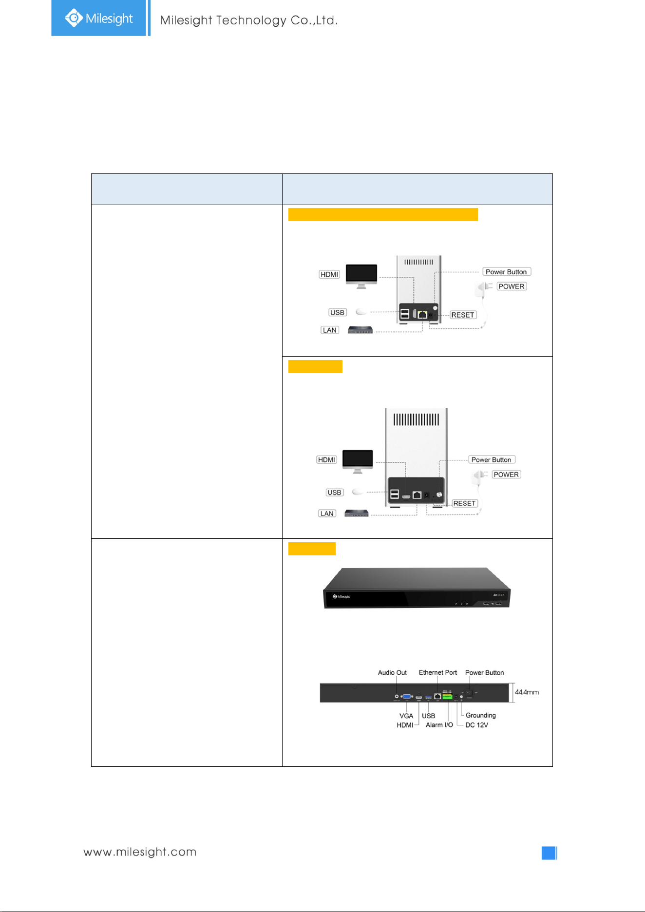
2.1 Panel Buttons
Model Hardware/Interface
4K H.265 Mini NVR 1000 Series
UI-1009-A (Firmware version: 71.xx.xx.xx):
UI-1009-NA:
4K H.265 Pro NVR 5000 Series
UI-5016-B:
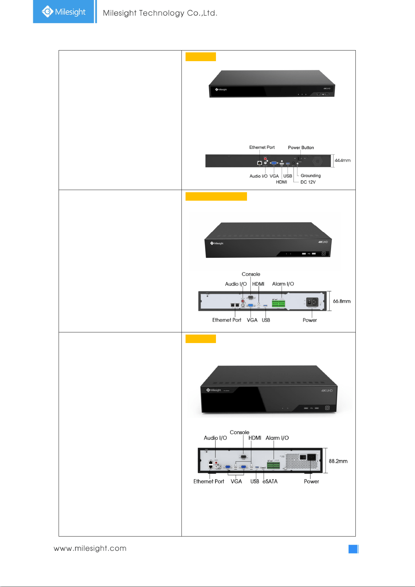
11
UI-5032-B:
4K H.265 Pro NVR 7000 Series
UI-7016-B/UI-7032-B:
4K H.265 Pro NVR 8000 Series
UI-8032-B:
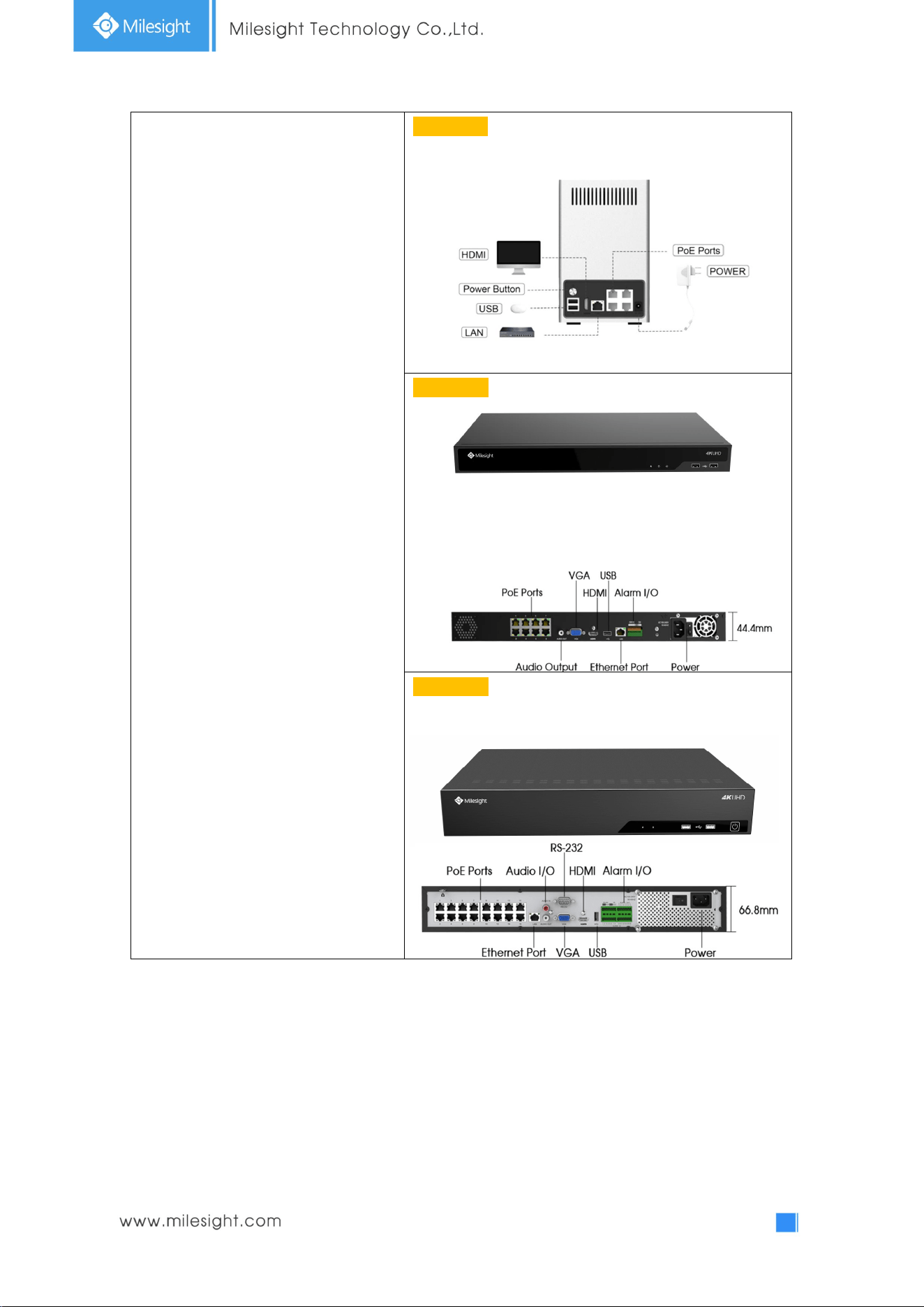
12
4K H.265 PoE NVR Series
UI-1009-PA:
UI-5016-PB:
UI-7032-PB:

13
2.2 Using a USB Mouse
Item Click Description
Left Button
Single- click
Live view: select the channel and show the toolbar of live view.
Menu: select and confirm.
Double-click
Switch between single screen to multi-screen when in live view
mode and playback mode.
Click and
drag
(1) Control rotation direction in PTZ mode.
(2) Set the target area in tamper-proof, motion detection and
privacy mask alarm settings.
(3) Drag the digital zoom area.
(4) Drag the channel and the time scroll bar.
Right Button Single-click
Live view: shows pop-up menu.
Menu: exit and go to Live View.
Scroll-wheel
Scroll up Scroll up the page.
Scroll down Scroll down the page.
2.3 Hard Disk Installation
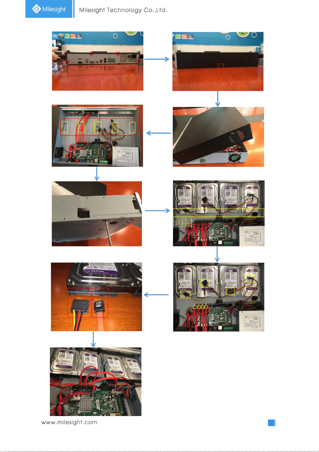
2.3.1 UI-7000 series Hard Disk Installation
Step1. Unscrew the back and both sides’ screws to open the upper lid.
Step2. Install the hard disks into NVR with screws shown in below pictures. (SATA Slots of hard disk
should be toward inside NVR.)
Step3. Join the power and data connectors to corresponding hard disk.
14
15
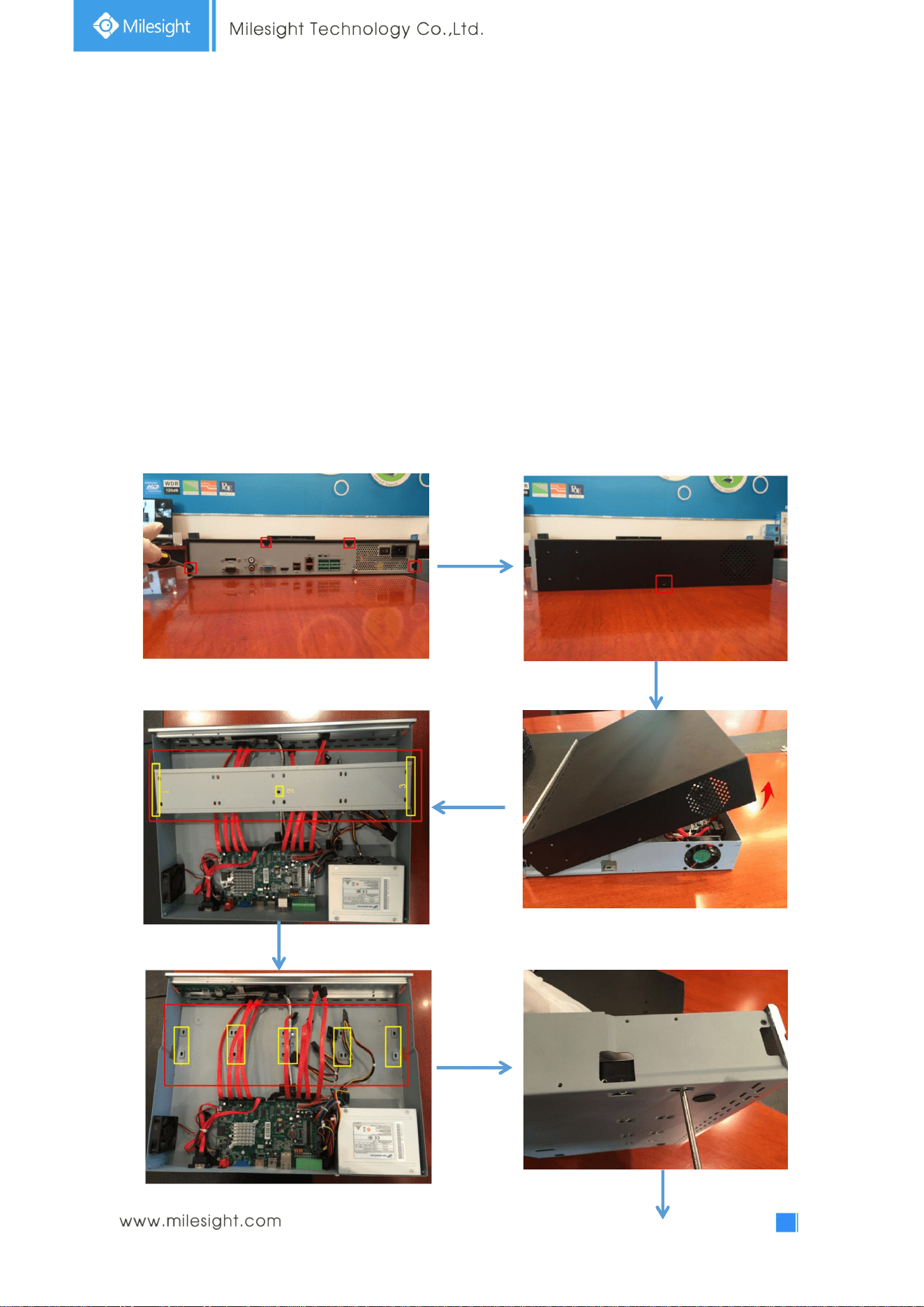
2.3.2 UI-8000 series Hard Disk Installation
Step1. Unscrew the back and both sides’ screws to open the upper lid.
Step2. Uninstall the upper hard disk panel.
Step3. Install the hard disks into NVR with screws shown in below pictures.(SATA slots of hard disks
should be toward inside NVR)
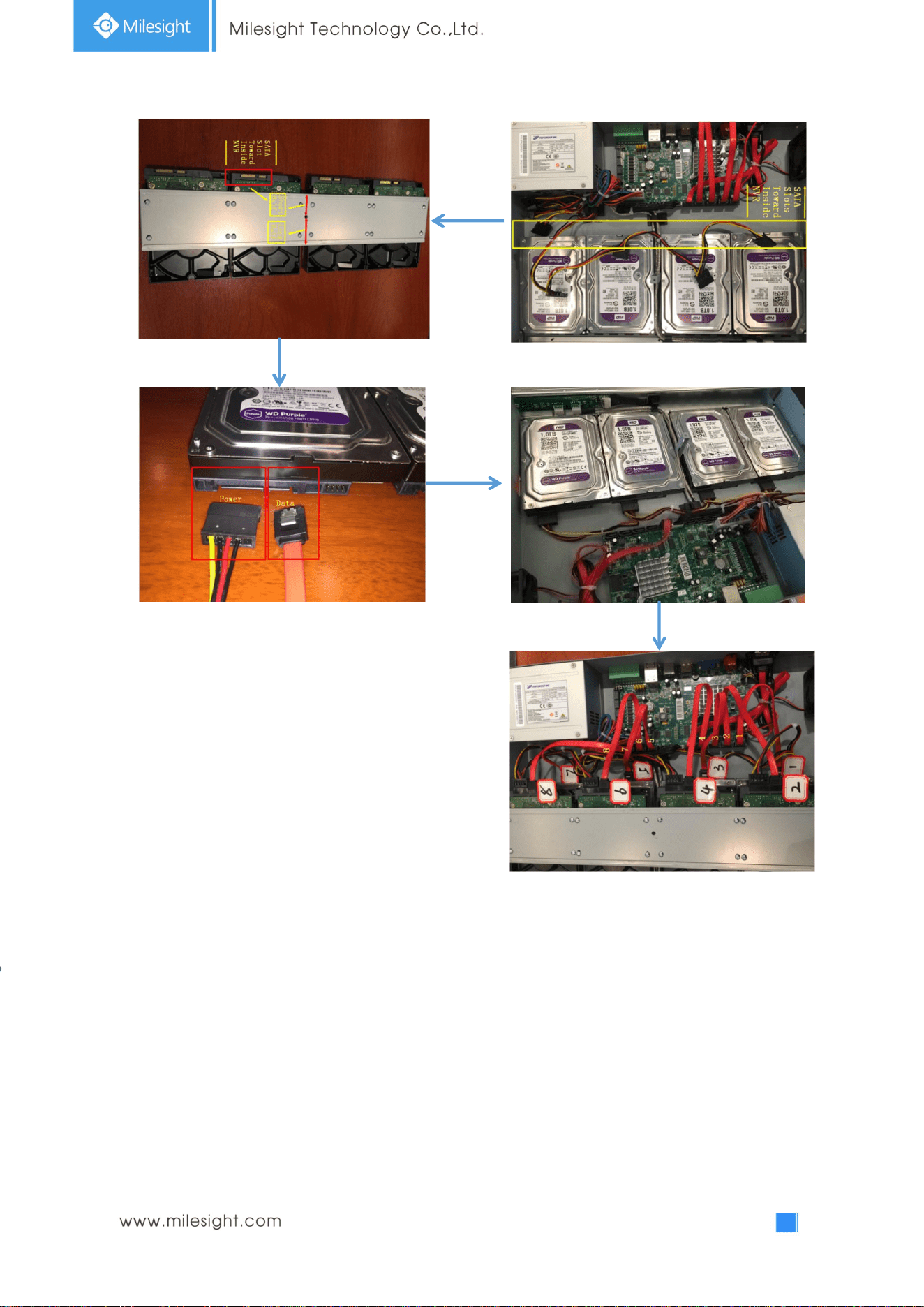
Step4. Join the power connectors to corresponding hard disks.(Install lower hard disk panel before
upper one)
Step5. Join the data connectors to corresponding hard disk.(Check the connection by below sequence)
16
Note:
1. The SATA slots are in SHORT HALF side and the SATA slot toward inside NVR.
2. The data connector sequence of UI-7000 series is different from UI-8000 series’.
17
3.Local Operation
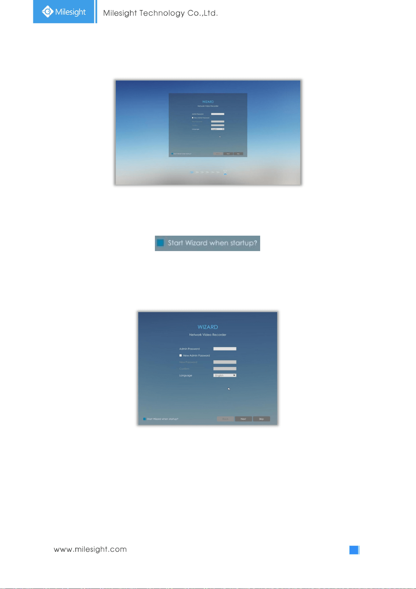
3.1 Wizard Setting
By default, the Setup Wizard will start once the NVR has been loaded. You can click check-box to turn
off the Wizard when startup.
The Setup Wizard will guide you to complete important settings, which makes NVR more user-friendly.
Step1. Input the user name, password and select system language.
Input new password to modify password .
Note: It is recommended to change the initial password for the safety of your equipment.
Note:
1. If the NVR firmware version out of the factory is xx.7.0.6 or above, the default user name is
“admin” and the default password is “ms1234”;
2. If the NVR firmware is upgraded to xx.7.0.6 or above from a lower version, the default
password will turn to “ms1234” after a reset, or it will keep the old default password
“123456”;
3. If the NVR firmware version is below xx.7.0.6, the default user name is “admin” and the
default password is “123456”.
18
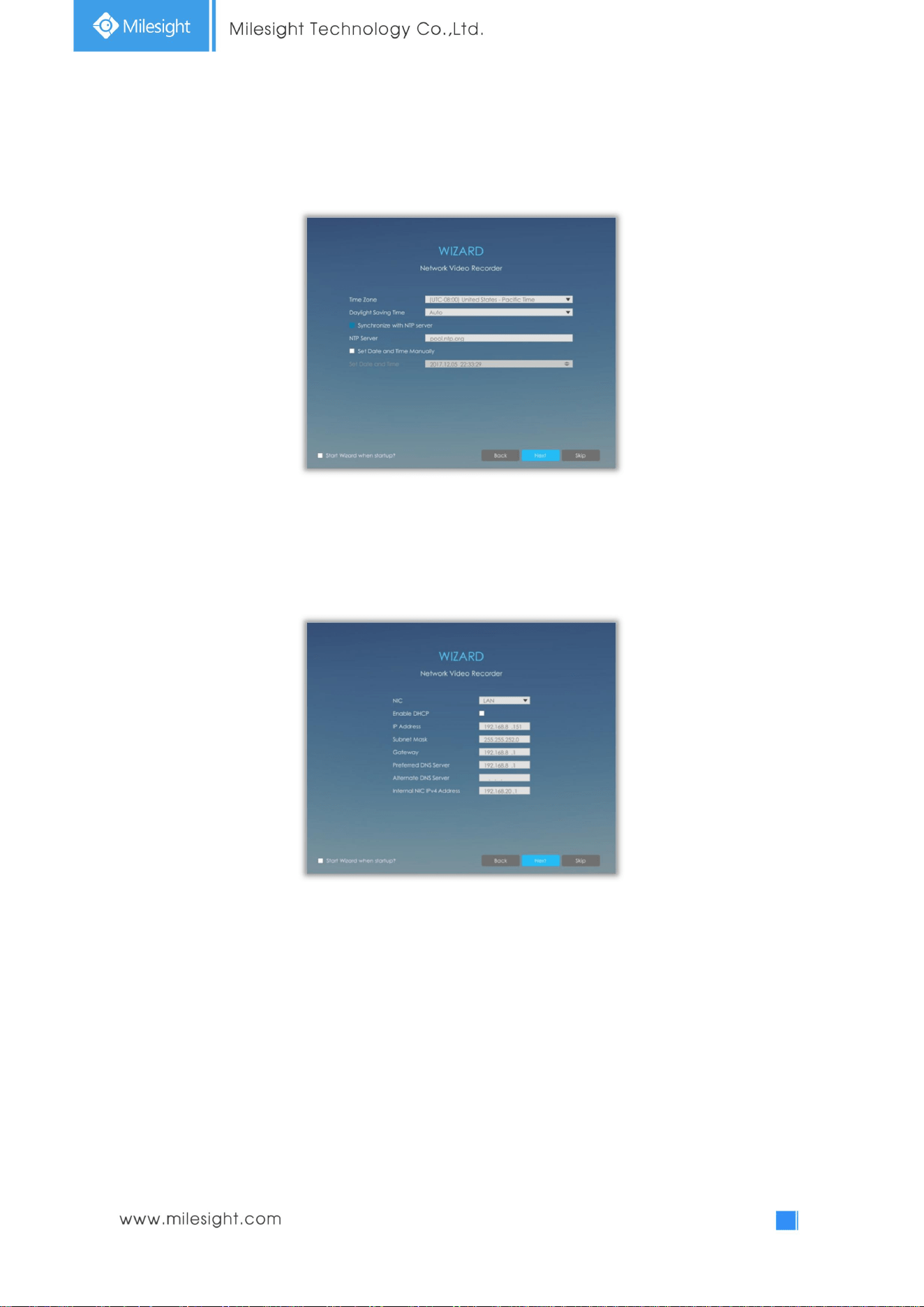
Step2. Date and time setting
Select the Time Zone and date via NTP or you can set date and time manually.
Step3. Network setting
Input the IP Address, Subnet Mask, Gateway and Preferred DNS Server.
Internal NIC IPv4 Address option is only for PoE NVR Series.
19
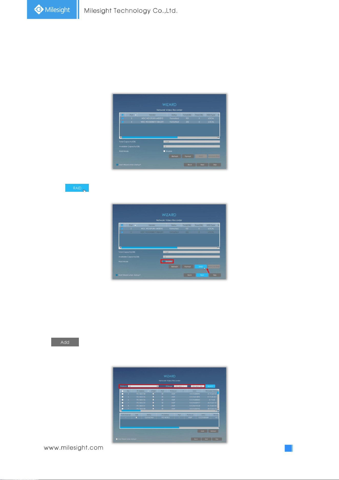
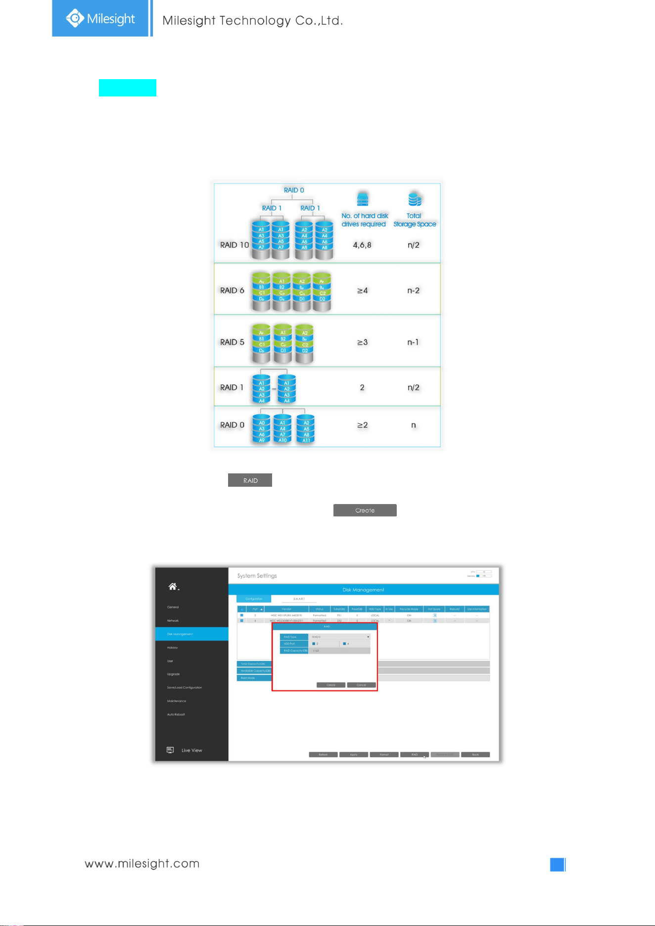
Step4. Disk Management
Automatically detect the hard disk installed in NVR, and it supports formatting hard disk.
You can create RAID in this page as well.
Note: RAID is only supported on Pro NVR 7000 series, PoE NVR 7000 series and Pro NVR 8000
series
Click to set up RAID for selected disk.
Note: RAID will be available after it was enabled and the device rebooted.
Step5. Camera Management
Search all the cameras in LAN by filtering Protocol and IP Range. Select cameras and click
to add them to NVR.
It can auto detect cameras that connected to PoE ports (only for PoE NVR).
20
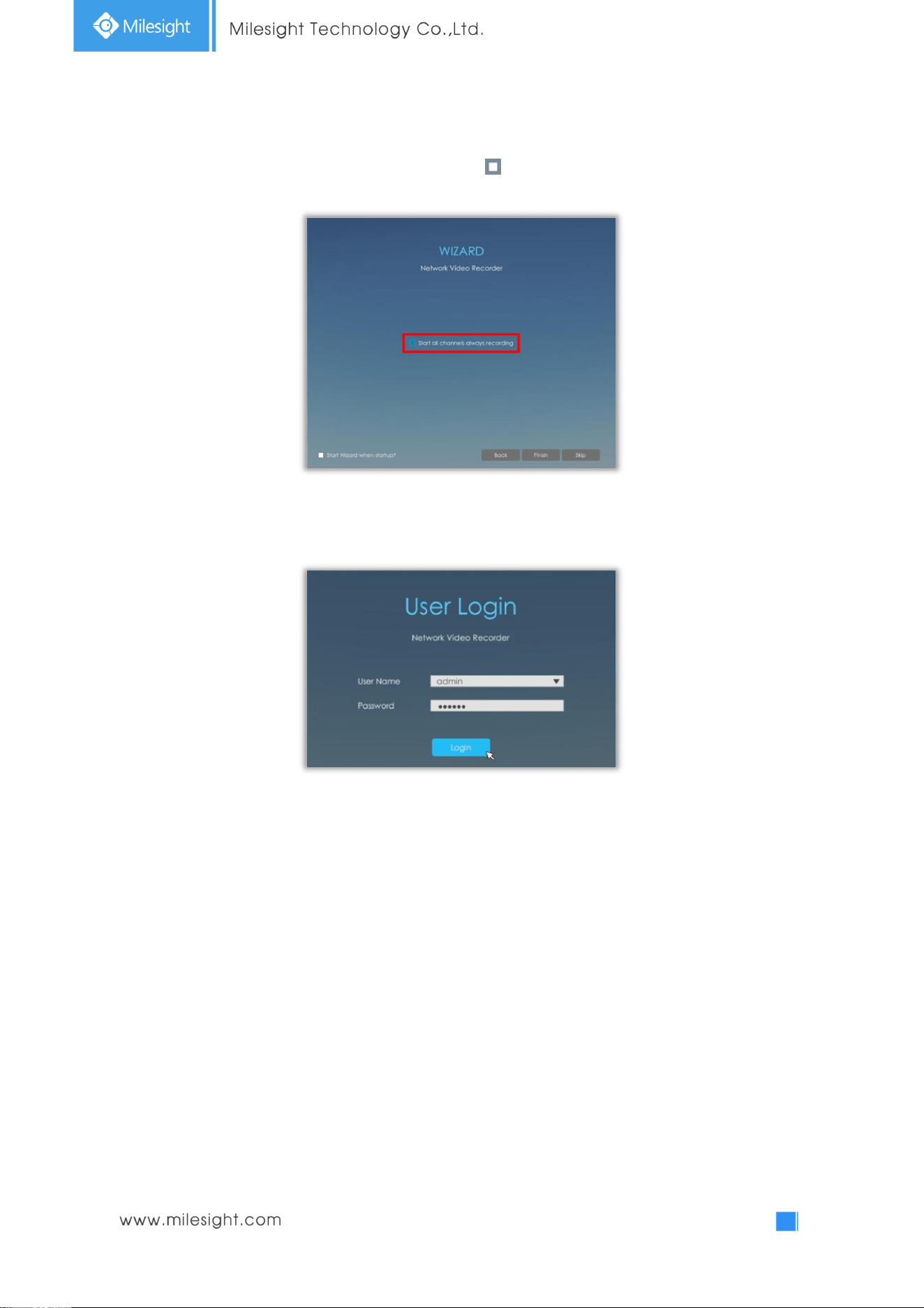
Step6. Record
The user can start all channels recording by clicking .
Step6. Login
Input the user name and password to login the system.
21
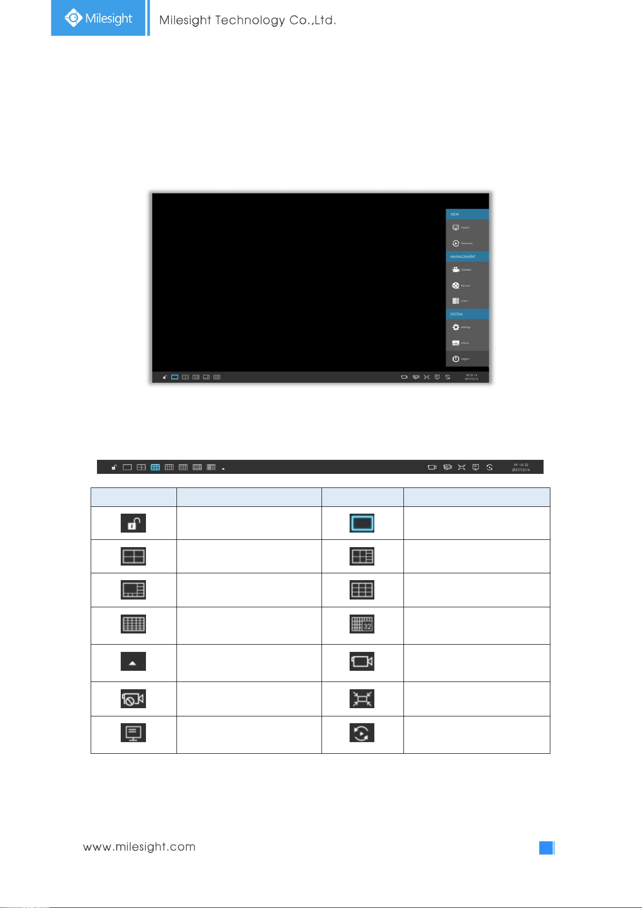
3.2 Live View
3.2.1 Live View
Main Menu and Tool Bar can pop up and hide automatically at the right side or bottom of the
interface.
Icons Descriptions Icons Descriptions
Lock/Unlock the tool bar One screen layout
4 screen layout 8 screens layout
1+7 screens layout 9 screens layout
16 screens layout 32 screens layout
Select other screen layouts Start all channels recording
Stop all channels recording Adjust image in proportion
Display settings Sequence
Note: Start all channels recording, Stop all channels recording, Adjust image in proportion and
Display settings are for all displaying channels.
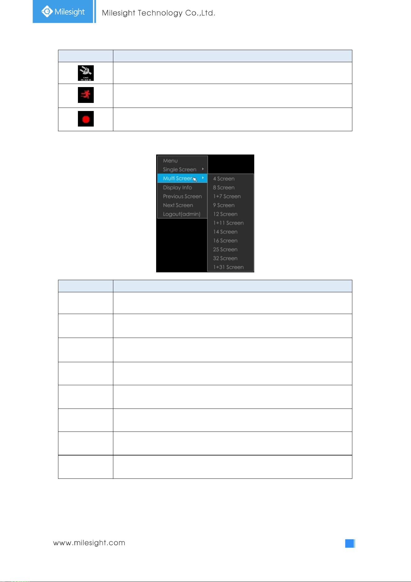
There are multiple icons on each channel displayed in live view, indicating different status of the
channel.
22
Icons Descriptions
It indicates video loss
It indicates motion detection alarm
It indicates that the current channel is recording.
Right click in the Live View and the quick operation menu pops up.
Item Descriptions
Menu Display Main Menu
Single Screen
The selected channel will be full screen. You could go back to previous screen layout
by
Sub Screen Ctrl Switch to sub screen to operate (Only for Pro NVR 8000 Series)
Multi-Screen Switch to multiple screen layouts
Display Info
Show channel information, including Camera Number, Bit Rate, Frame Rate and
Frame Size
Previous Screen Switch to previous screen
Next Screen Switch to next screen
Logout Log out current user account
23
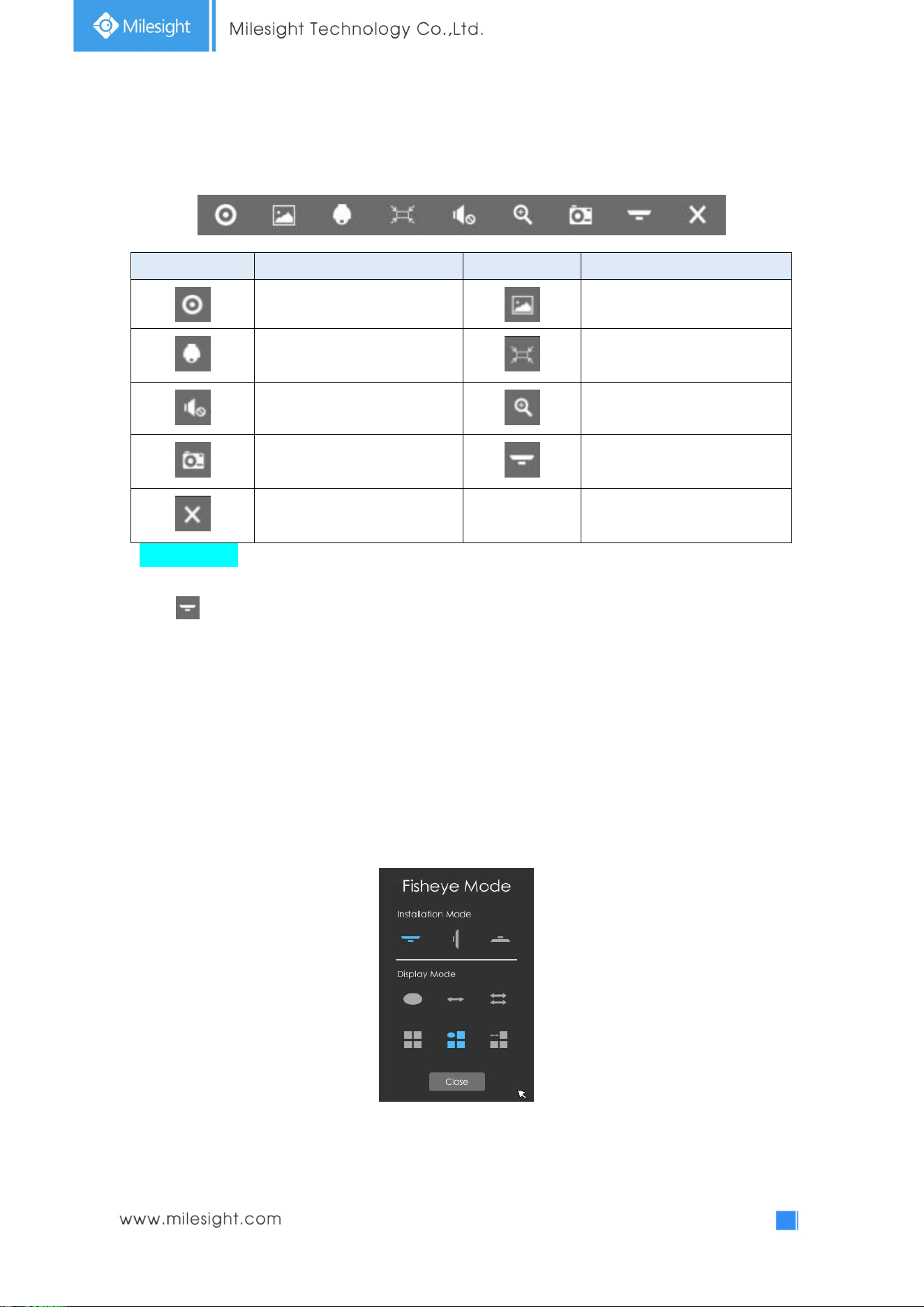
Quick Operation for single channel
In live view interface, left click the channel, the quick menu will appear.
Icons Descriptions Icons Descriptions
Manually record Image Configure
PTZ control Original/Resize the image
Audio on/off Digital zoom
Snapshot manually Fisheye Mode
Close menu
Fisheye Mode:
Click to expand Fisheye Mode panel, then set installation mode and display mode for Milesight
Fisheye camera.
Installation Mode: Ceiling Mount/ Wall Mount/ Table Mount
Display Mode: Fisheye View/ 360 Panorama View/ 180 Panorama View/ 4PTZ/ Fisheye + 3PTZ/
Panorama View+3PTZ
Note: It is recommended to set Fisheye compatibility to Bundle Stream in Camera side before
adding to NVR.
24
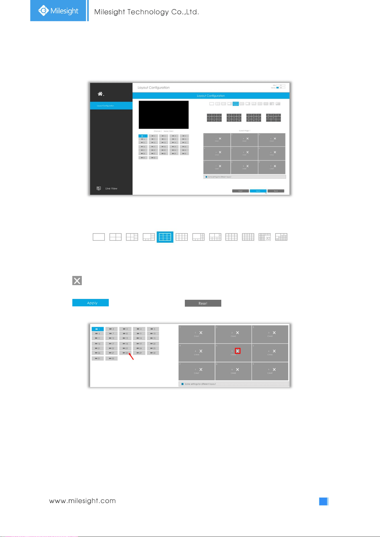
3.2.2 Layout
Step1. Select a layout format.
Step2. Set desired channels.
Click to close a channel. Select a window and then select a desired channel to add in.
Click to save the settings or click to reset the layout.
25
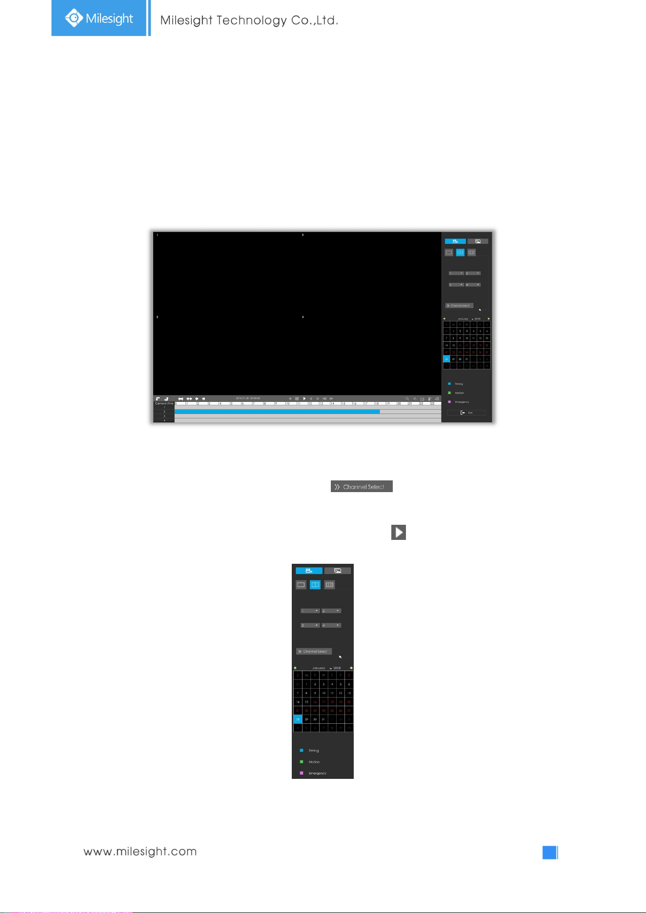
3.3Playback
3.3.1 Video Playback
Playback supports to playback video according to recorded time and to play recorded video files in
specified time period. Synchronous playback of multi-channel is supported.
Step1. Select screen layout, channels date and recording type.
Select playback layout and channels. User can click for quick selecting channels. Click
the date in red when there are recorded files of the selected channels, the record type with recording
data will be shown as below. Select the record type and then click to playback.
Note: Only the day with red letters means that there are record files.
26
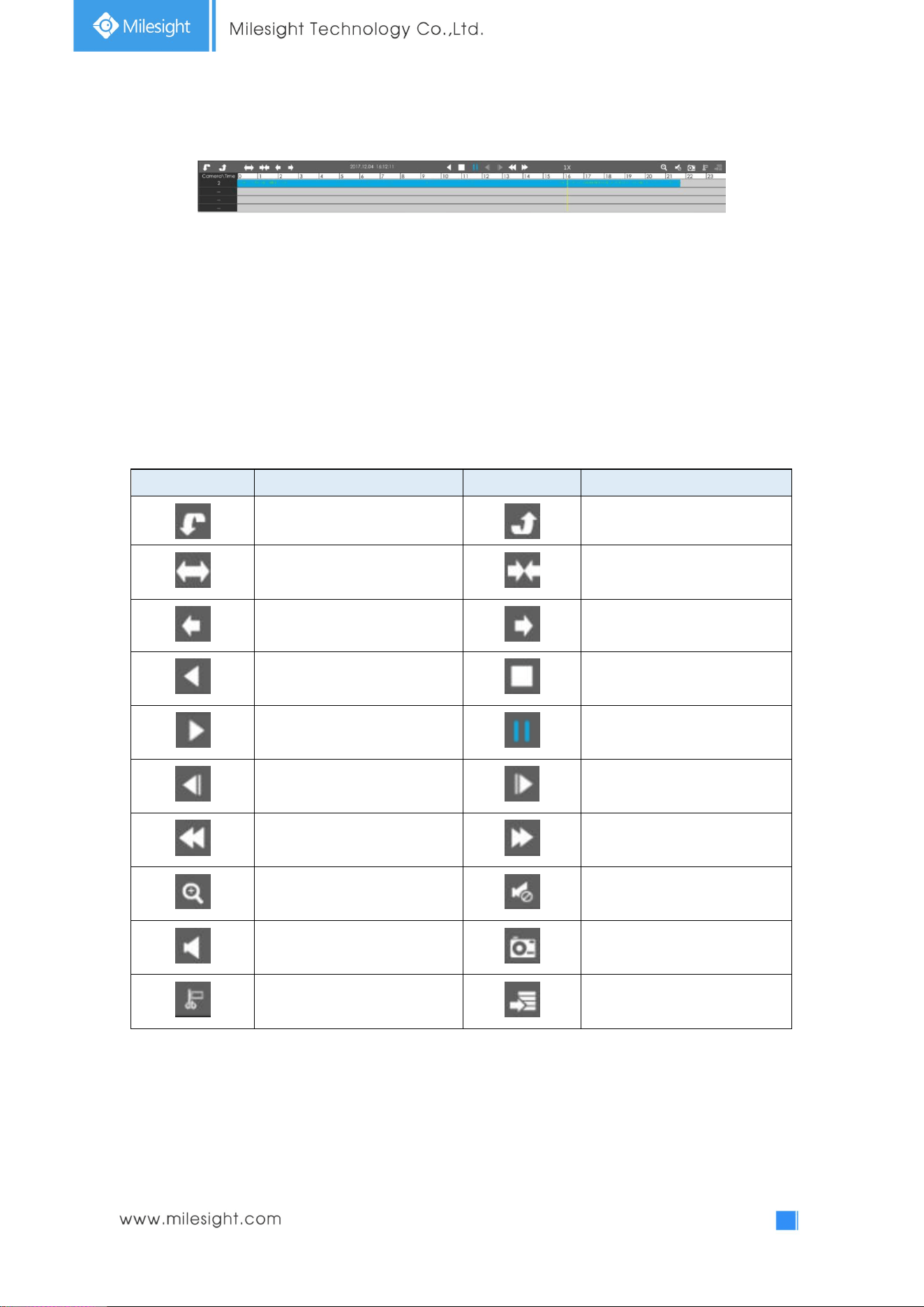
Video Playback Tool Bar Description
The tool bar can display multi-event record. It shows that in this record period what kind of event has
happened. The symbolic meaning of each color is:
Blue—Timing Green --- Motion
Red --- Alarm Purple --- Emergency
And take this bar above as an example, it means that in this recording period, timing and motion
event have been triggered.
Icons Descriptions Icons Descriptions
Next 4 cameras Previous 4 cameras
Timeline zoom in Timeline zoom out
Timeline forward Timeline backward
Rewind Stop
Play Pause
Step reverse Step forward
Speed down Speed up
Digital zoom Audio on
Audio off Snapshot
Timeline cutting Download
27
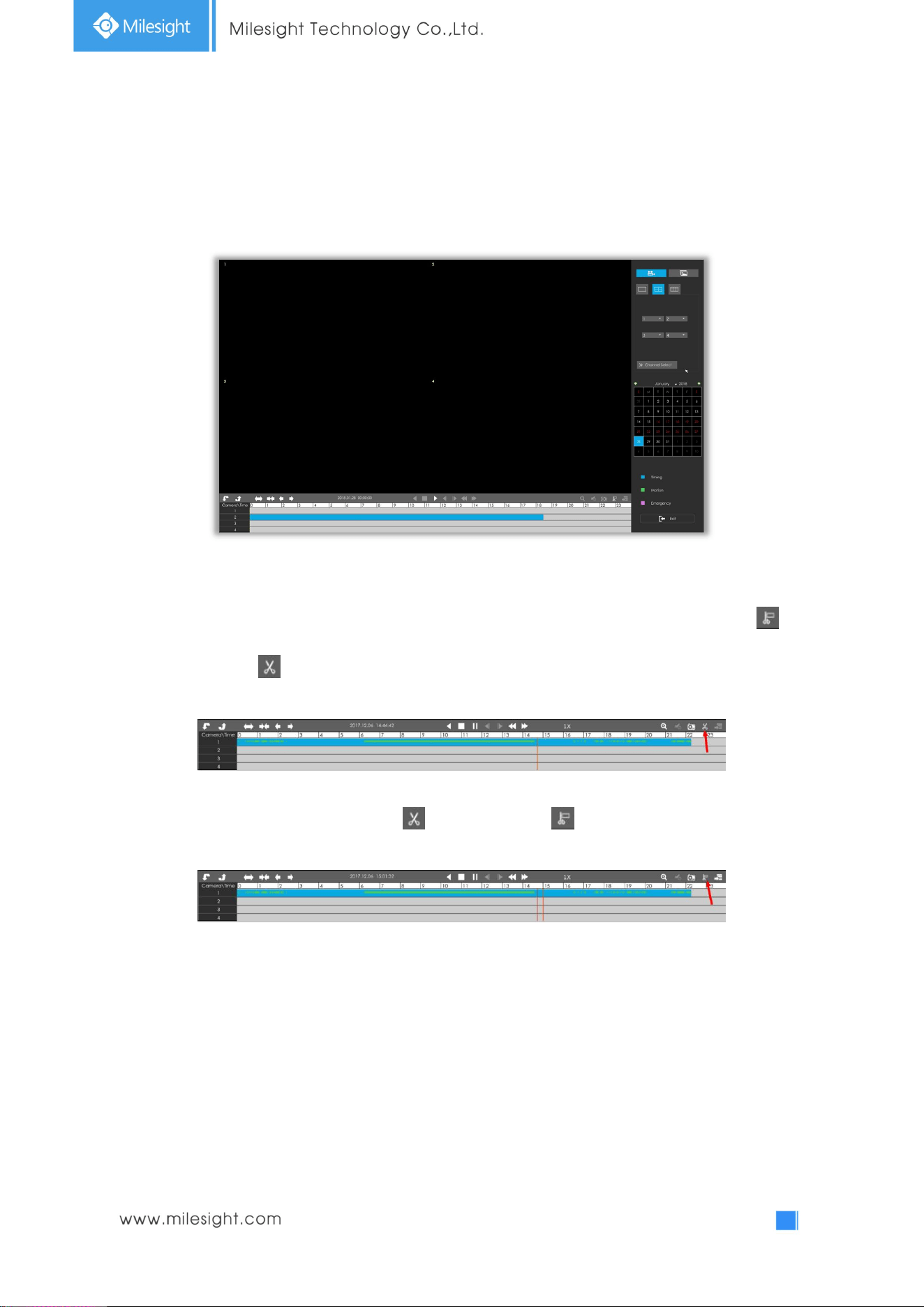
3.3.2 Video Files Backup
Recorded files can be backed up by various devices, including USB flash drives (USB flash disk, USB
HDD, USB writer) and eSATA
, etc.
Step1. Select Recorded files.
Select the channel and date you want to backup, then select the start time at timeline and click ,
it will change into which means cut begins.
Select the end time at time line and click , it will change into , which means cut ends.
28
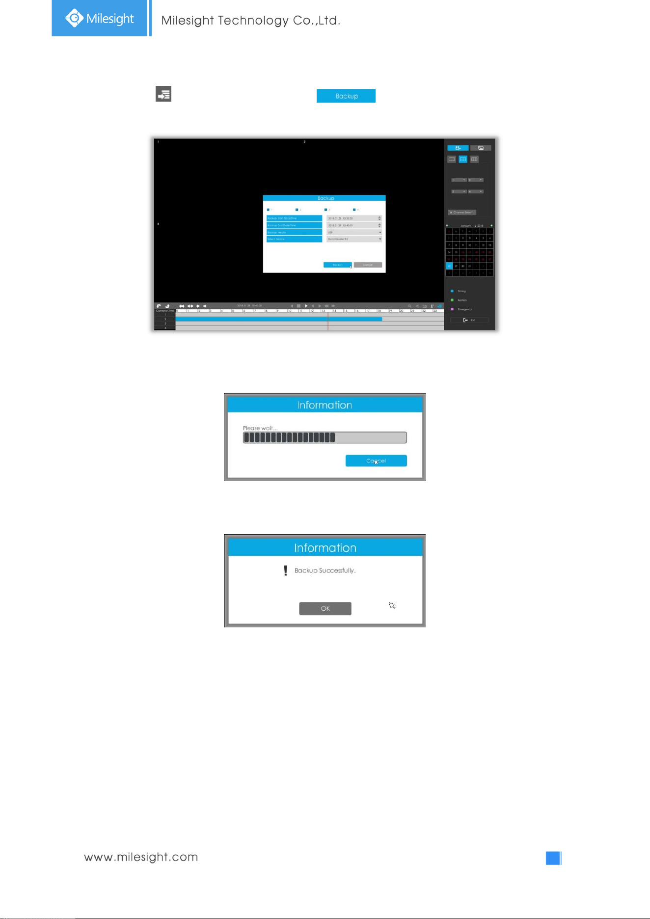
Step2. Click , select Backup media and click .
Step3. The window will prompt: Please wait…
Step4. When all backup files have been exported, ‘Backup Successfully’ will be prompted.
Note: The download time of files depends on the time length of video you want to backup.
29
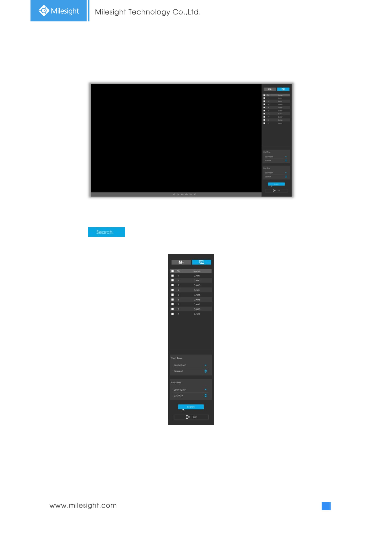
3.3.3 Picture Playback
Step1. Search and look for the snapshot files saved in HDD by selecting channels, start time and end
time, click .
30
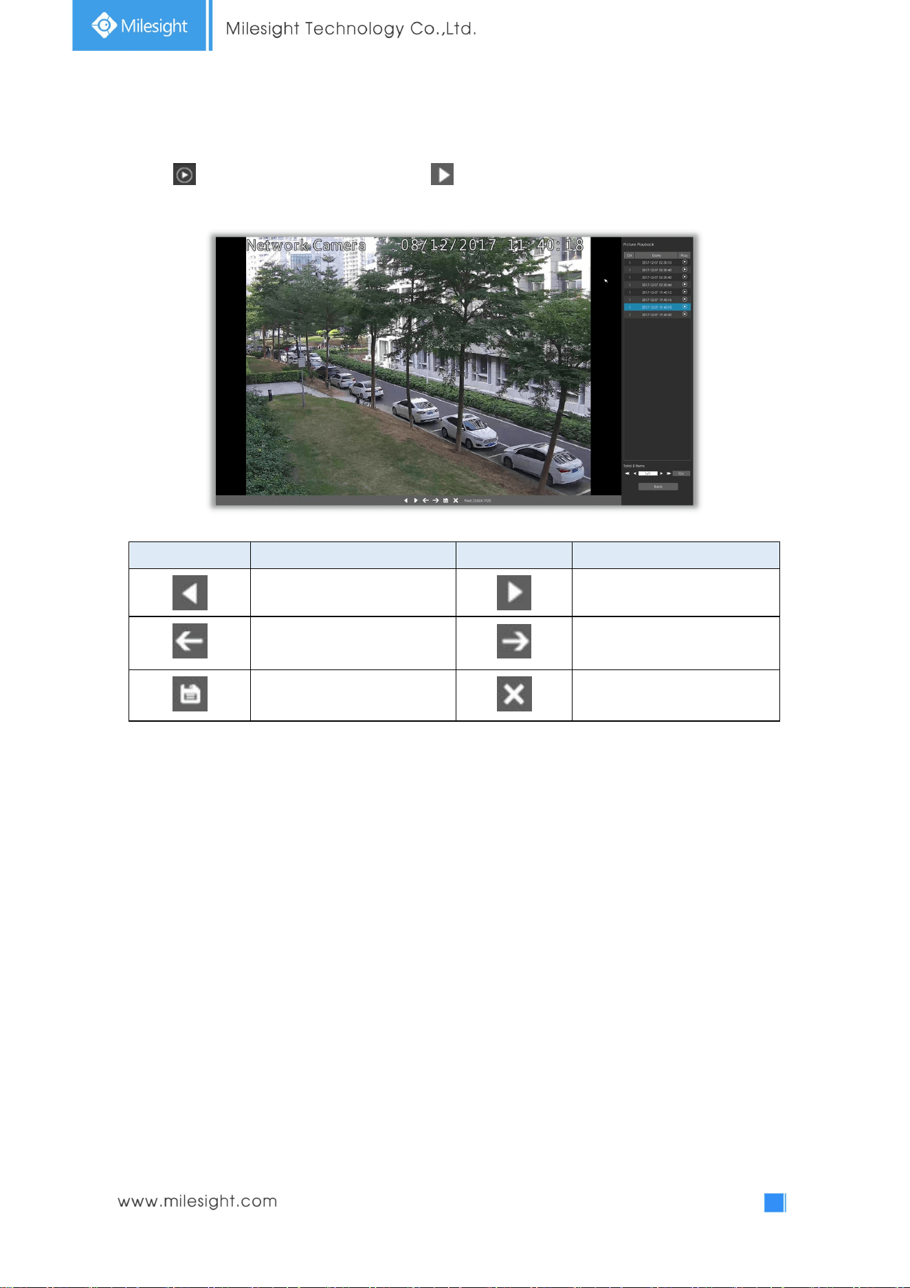
Step2. Enter Picture Info List and look up the pictures.
Click to play the selected picture, or click to auto play pictures.
Icons Descriptions Icons Descriptions
Play backward Play
Previous picture Next picture
Download picture Back to search interface
31
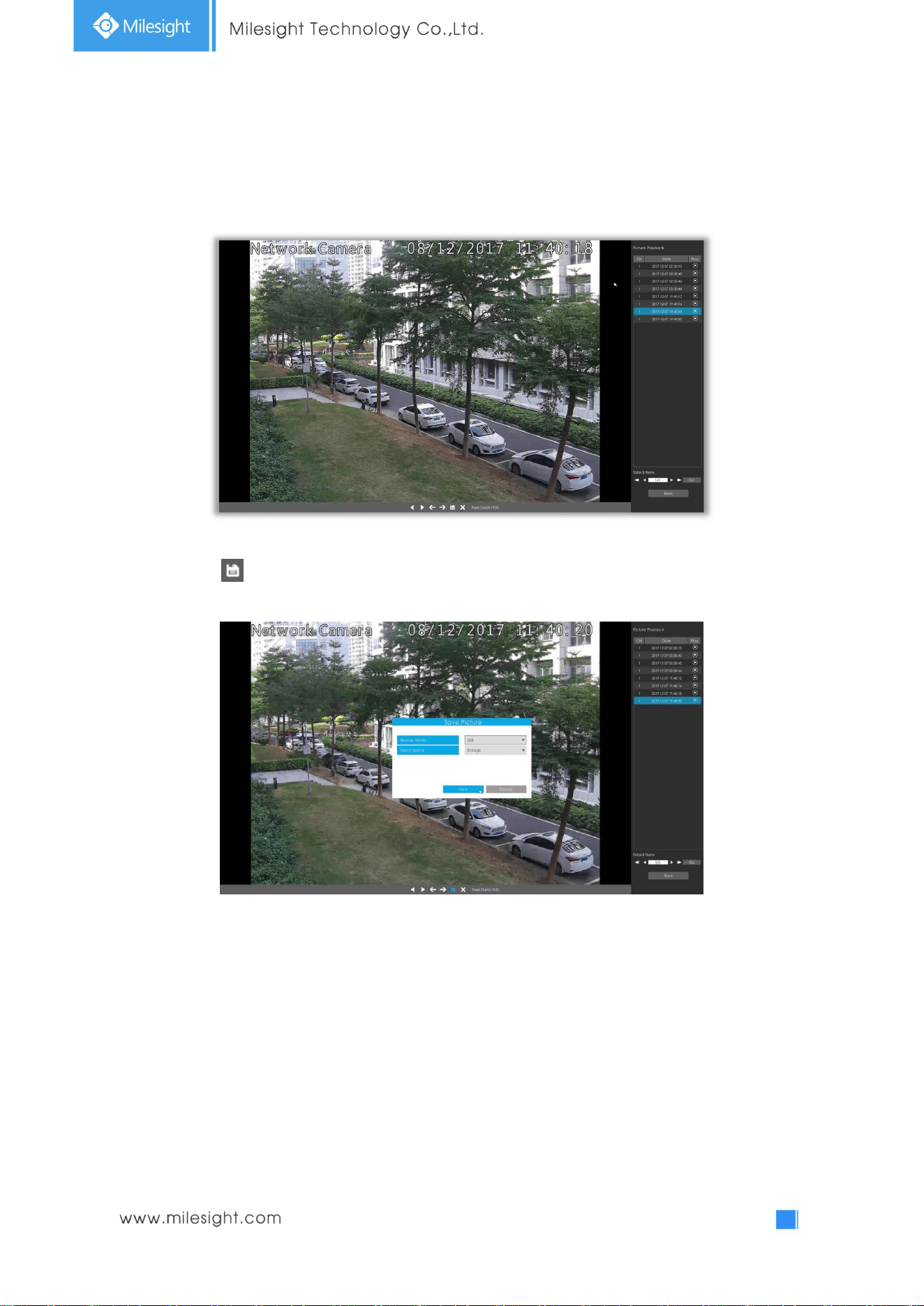
3.3.4 Picture Files Backup
Step1. Select pictures you want to backup in picture playback interface.
Step2. Click and select backup media to save picture.
32
3.4 Camera Settings
Before configuration, please ensure that the camera is connected to the same network as your
NVR and that the network setting for your NVR is properly set.
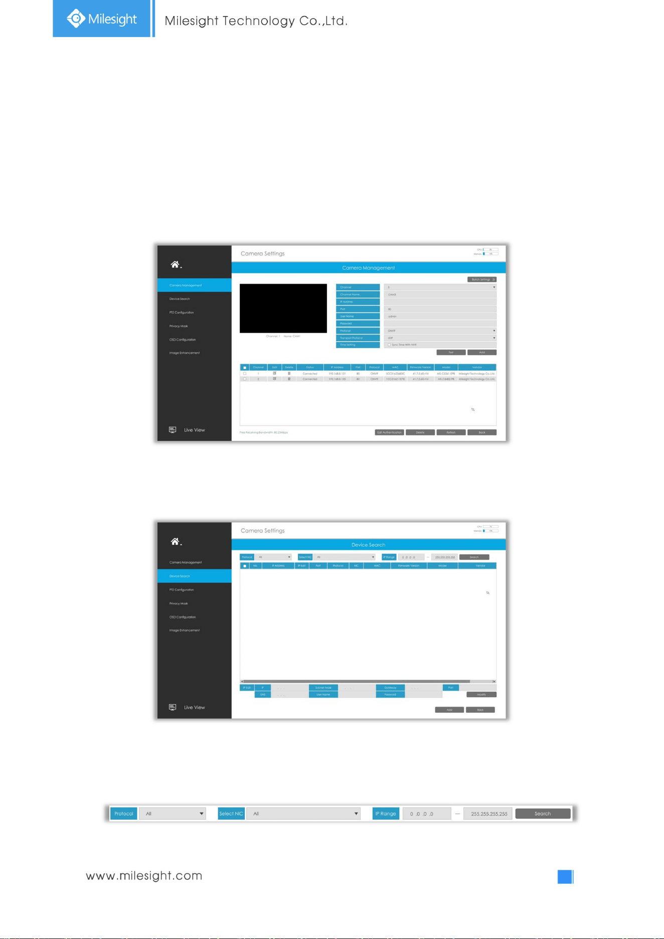
3.4.1 Camera Management
Step1. Add camera.
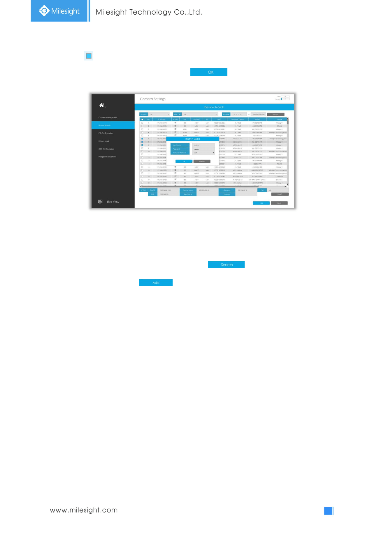
Method1. Add camera through Device Search interface. ‘Settings’à ‘Camera’ à ‘Device Search’.
1. Select IP Range, NIC and Protocol, which includes ALL, ONVIF and MSSP.
MSSP: You can search out all Milesight camera which has different network segment in the LAN.
33
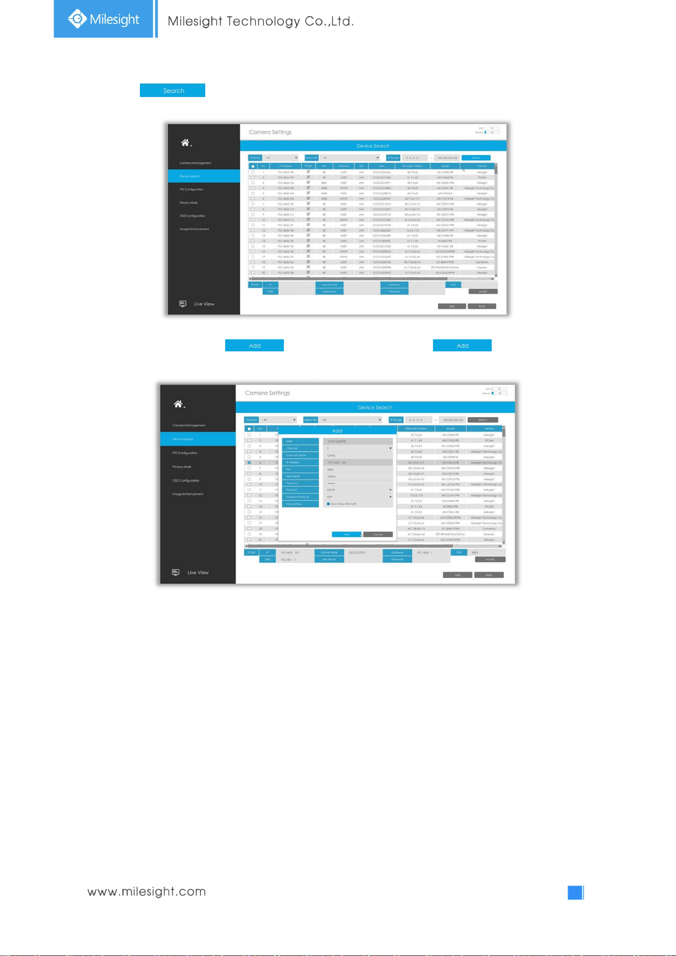
2. Click button to search cameras at the same LAN with NVR.
3. Select one channel, click button, input password and click button to finish.
34
3. Check to batch adding the network cameras if they are with the same password, you can
choose TCP or UDP transport protocol for it. Click to finish batch adding.
Note: The steps for adding the third party PoE cameras plugged into Milesight PoE NVR:
① Set camera’s IP segment to the same as NVR PoE NIC before plugging to PoE NVR;
② Select PoE for NIC in Device Search interface, click to search out cameras;
③ Select cameras and click to add them.
35
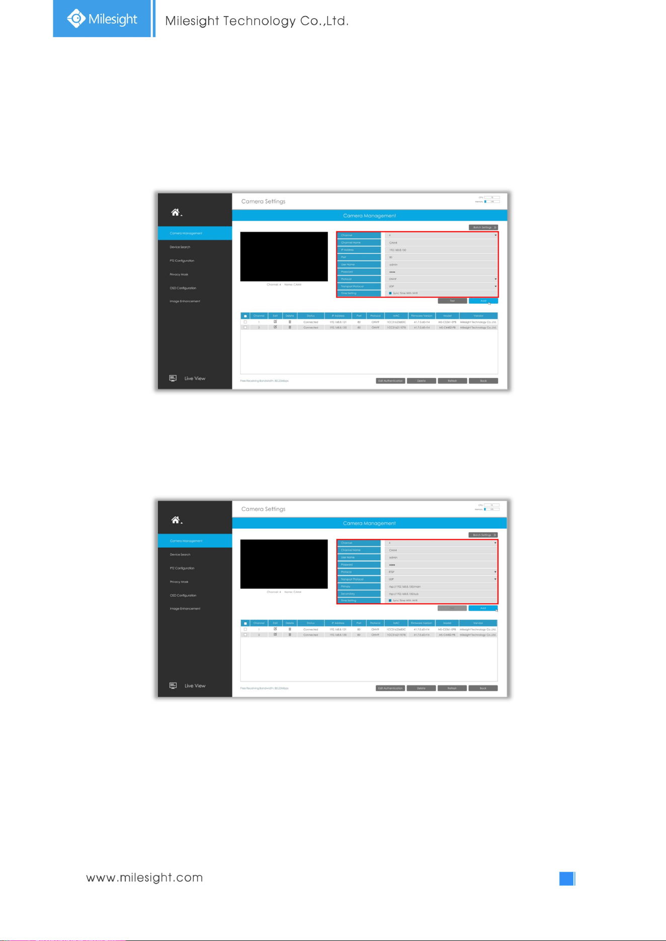
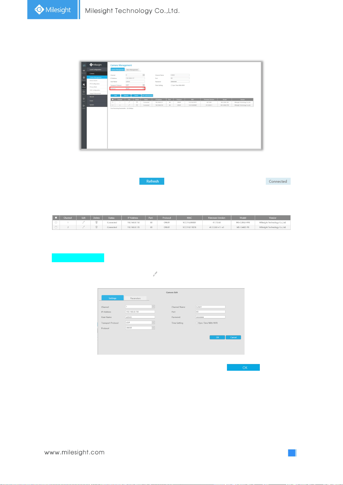
Method2. Add camera through camera management interface. ‘Settings‘à ‘Camera’ à ‘Camera
Management’.
Select channel ID, input complete information, then click [Add] button.
There are three protocols available for camera connection:
l ONVIF: You can add any ONVIF IP cameras with ONVIF protocols.
l RTSP: You can add any IP cameras with RTSP protocol streams (Port: 554). It needs you
to input complete resource path of the IP camera to add it. Take Milesight device for example,
the resource path of main stream is “rtsp://IP:port/main” and secondary stream is
“rtsp://IP:port/sub”.
36
l MSSP: You can add Milesight cameras which are in the same LAN with MSSP protocol.
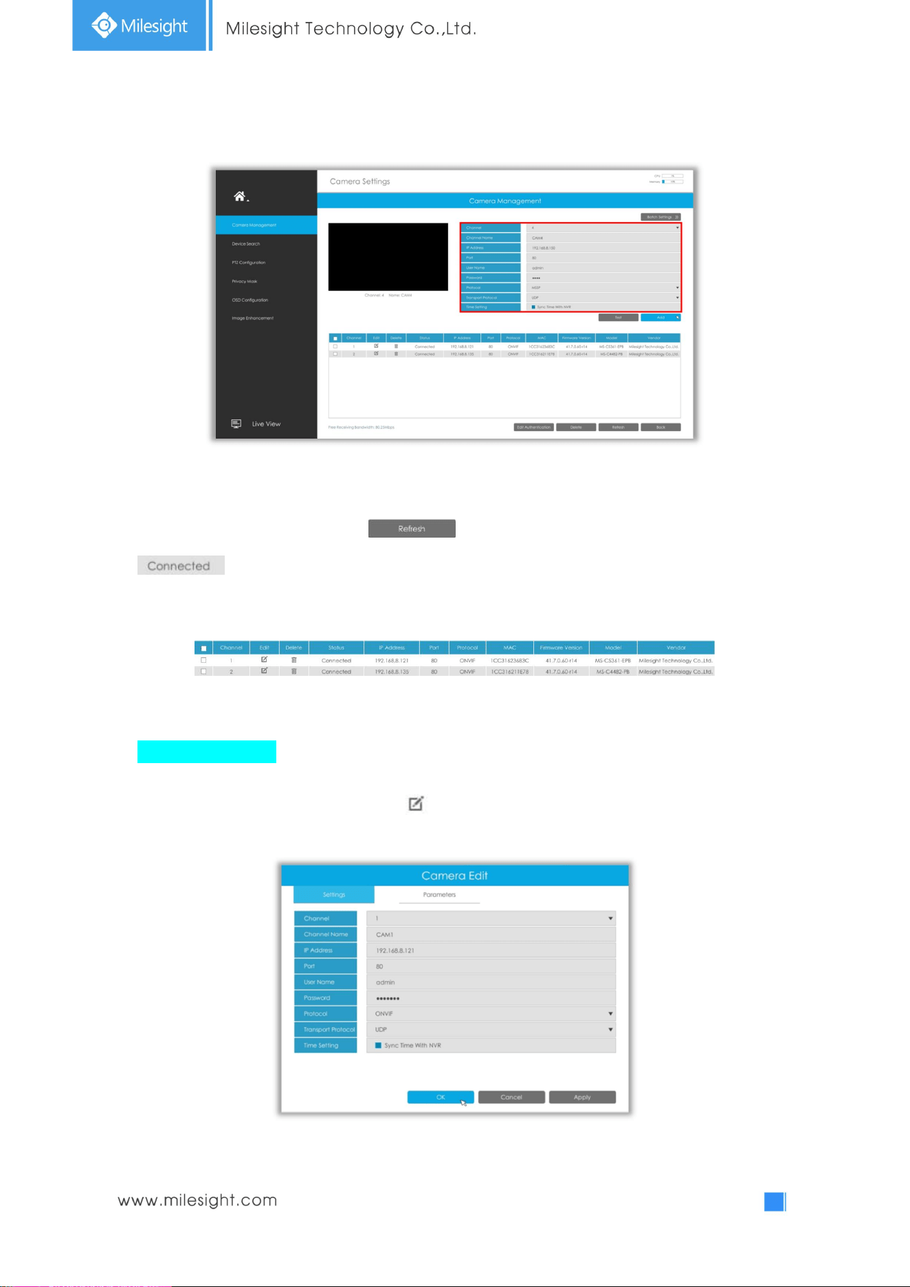
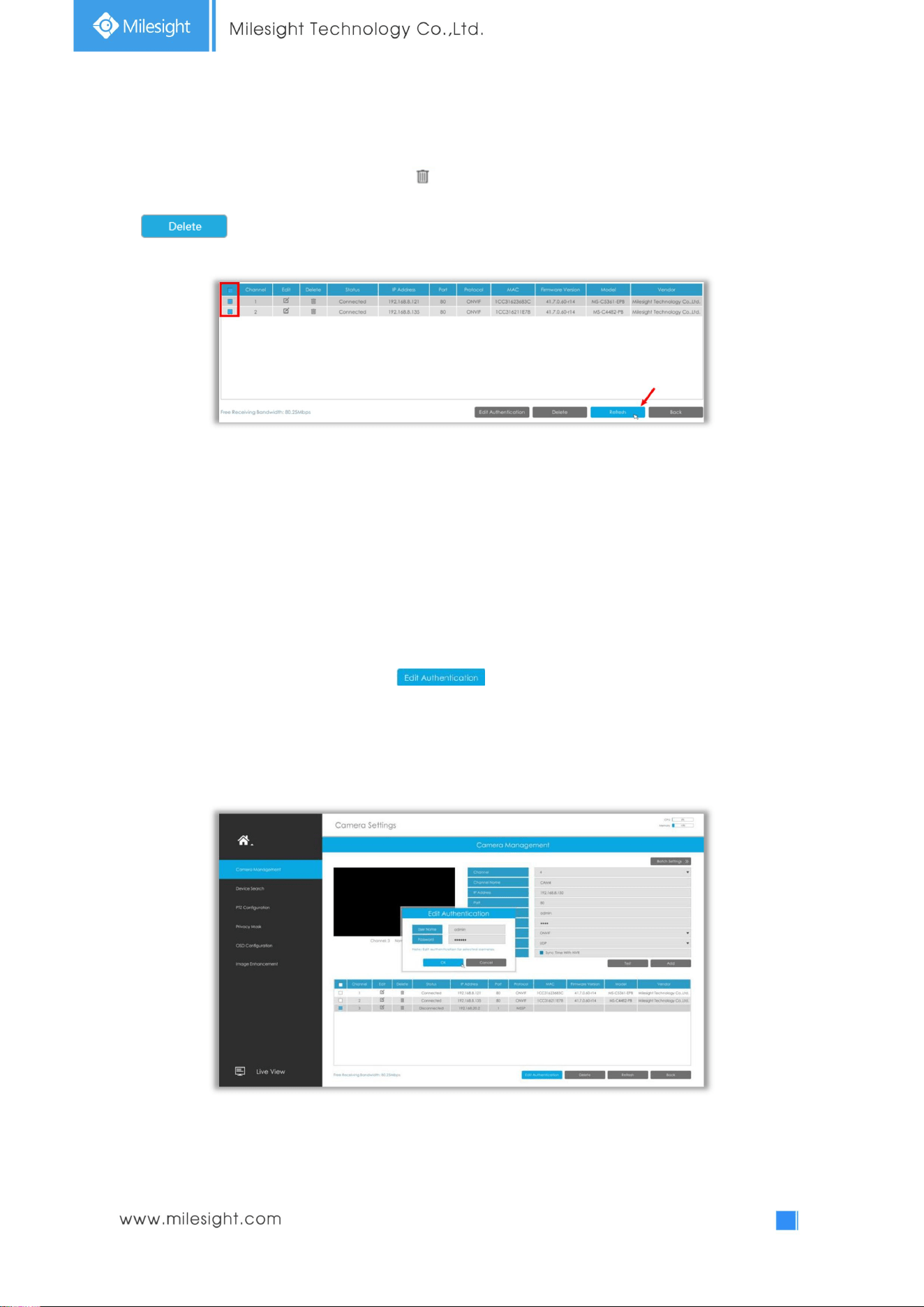
Step2. Check the connection status.
After adding the IP channels, click button on Camera Management interface, then
appears under Status. If it doesn’t appear, you need to check if the network is
connected or whether the user name or password is correct or not.
Step3. Configure camera.
Configure one camera
After successfully adding the camera, click to re-edit the channel info.
37
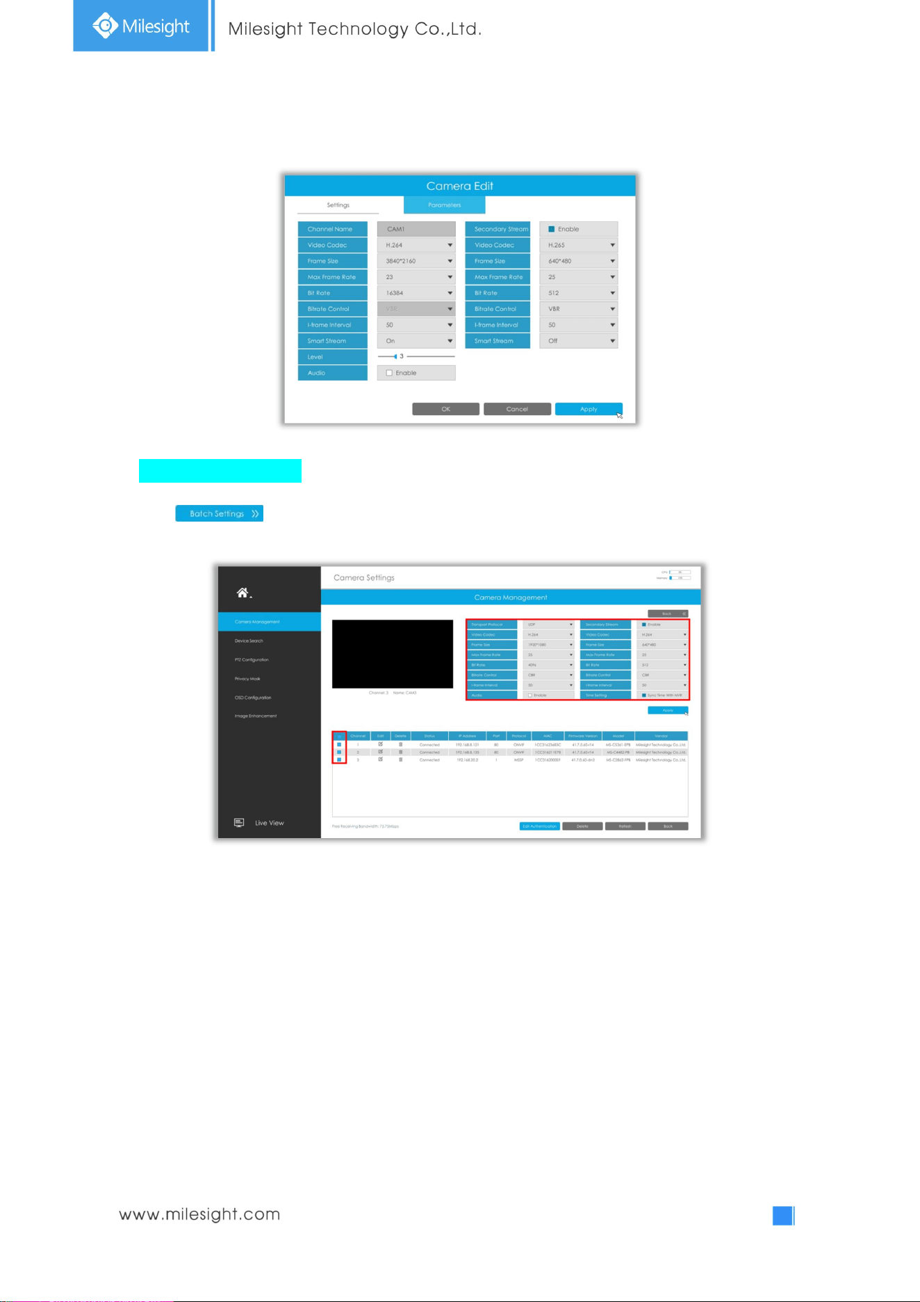
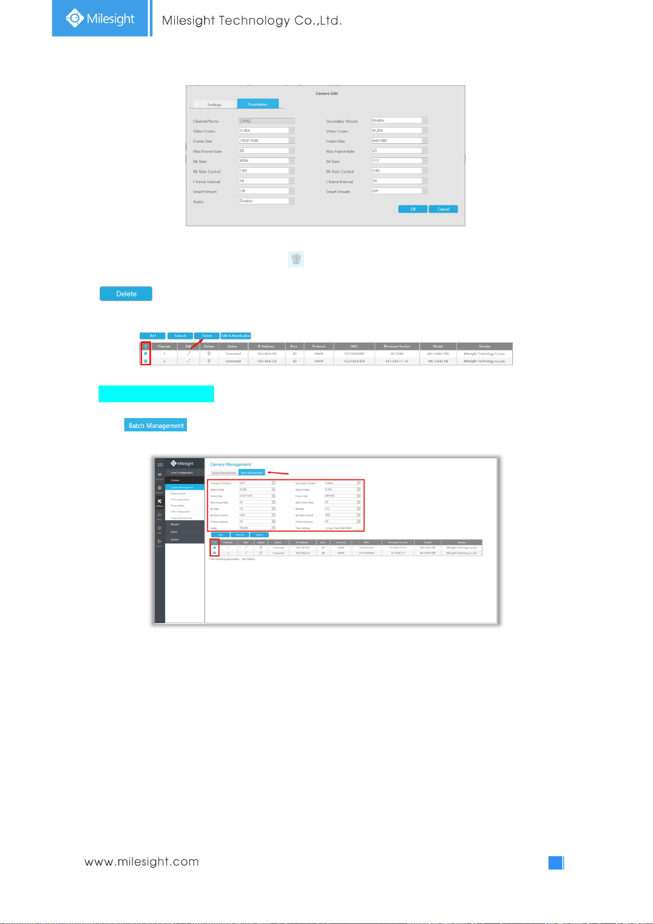
Select Parameters page to re-edit parameters of this channel. Click [OK] to save the configuration.
Batch configuring camera
Click , select multiple channels and set parameters of cameras.
38
Step4. Delete camera.
You can delete this channel by clicking , or you can select multiple devices and then click
to delete.
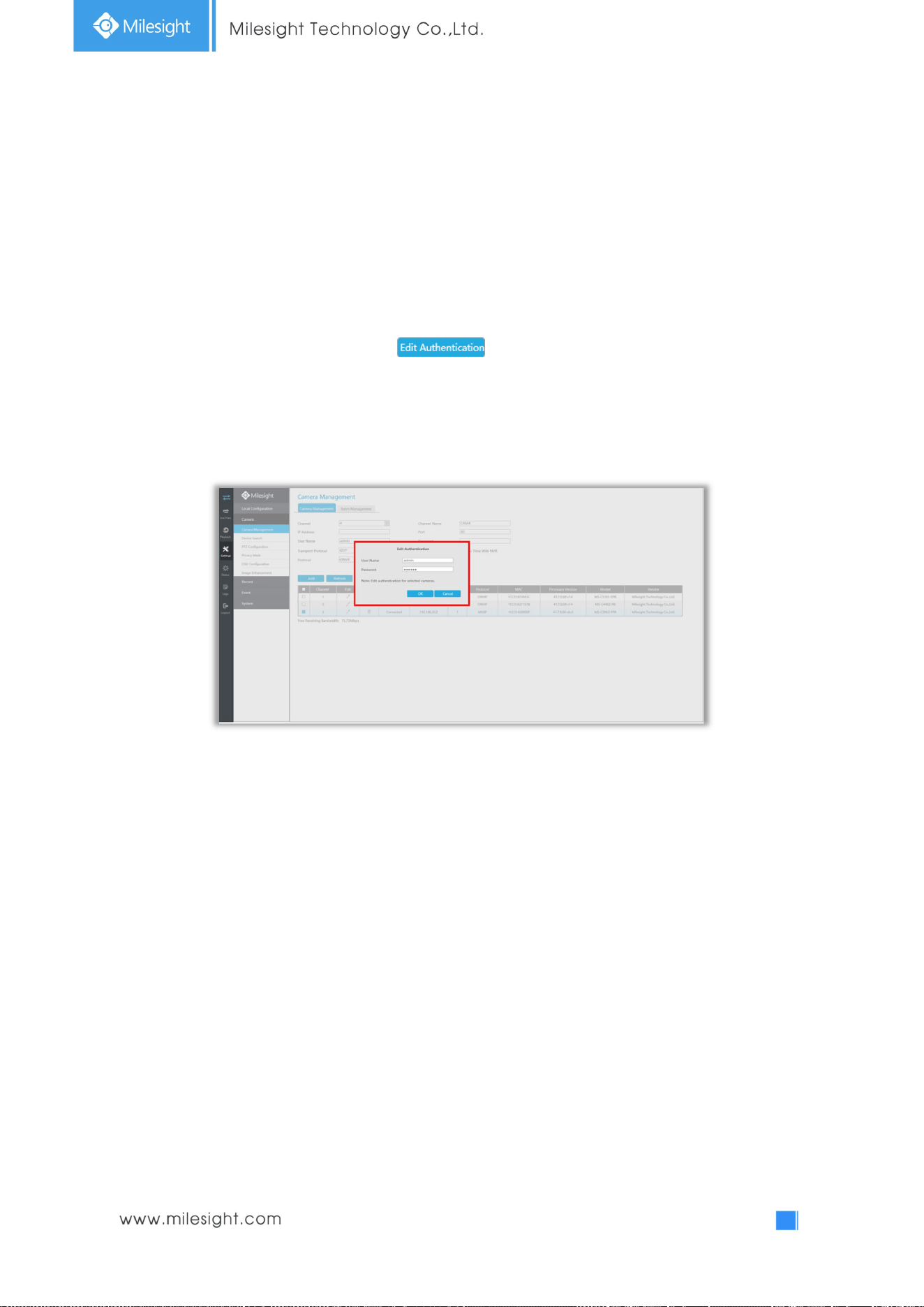
Step5. Configure PoE Channel(Only for PoE NVR)
1. Connect camera to PoE port, it will detect the camera automatically.
2. If the camera's password is "ms1234", it will be successfully authenticated and be changed into the
same network segment with internal NIC IPv4 address, then the camera will be connected
successfully.
3. If the camera's password is not "ms1234", the PoE channel will show disconnect status. You need to
input the camera's password by clicking to realize authentication ( you can also
multi-select the devices and then click this button). Then the camera will be changed into the same
network segment with internal NIC IPv4 address and will be successfully connected. In next time, NVR
will use the password you input to authenticate this camera when you re-plug it.
39
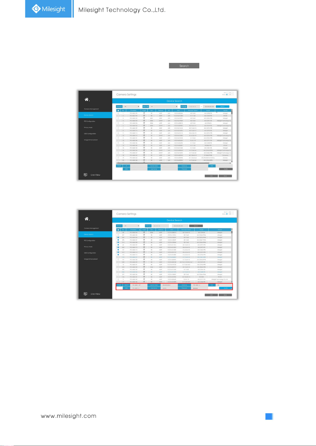
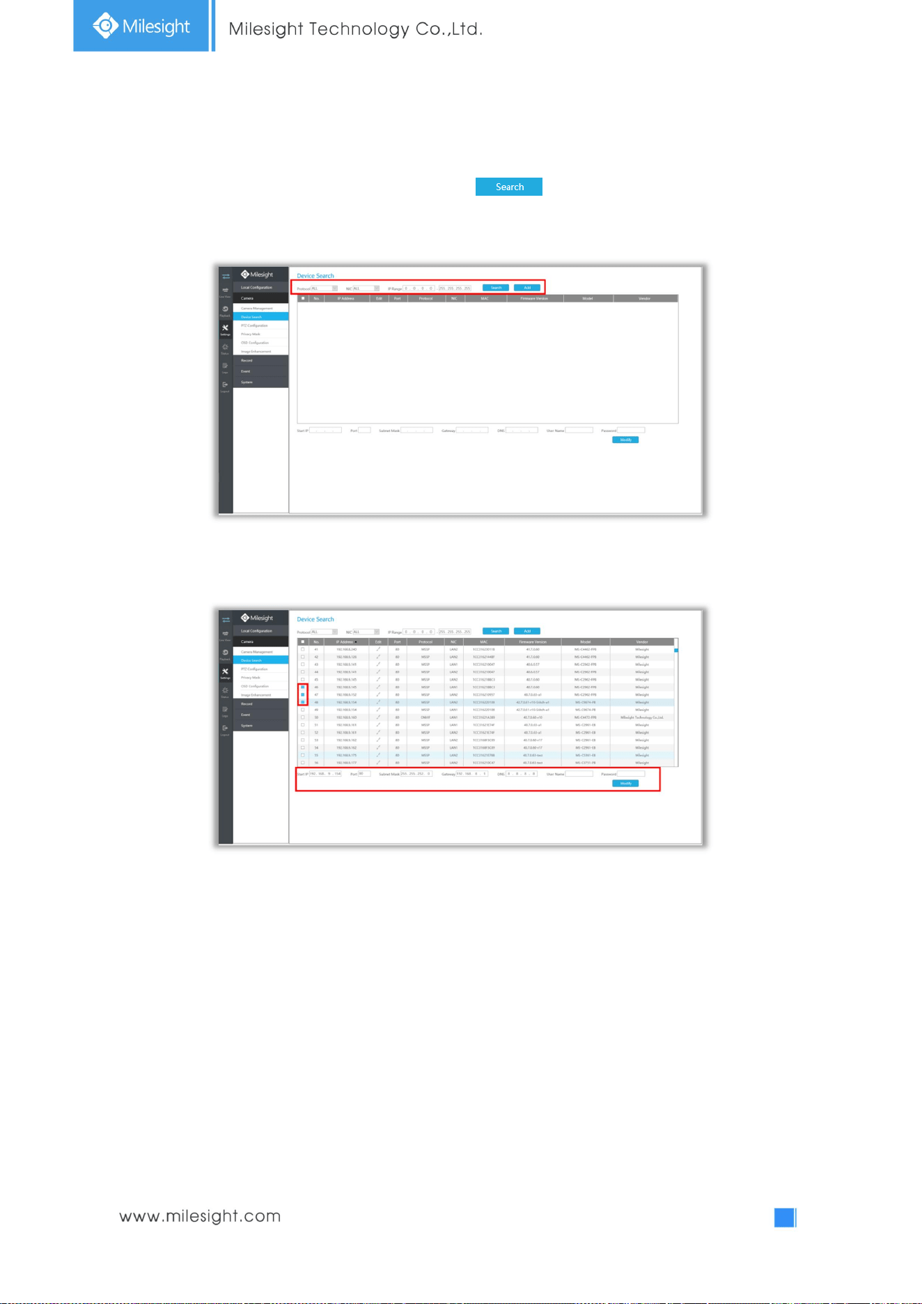
3.4.2 Device Search
Select Protocol and NIC, then set the IP range, and click to quickly search the IP
devices that support selected protocol at the same LAN with NVR.
Select channels andbatch editing their IP information.
40
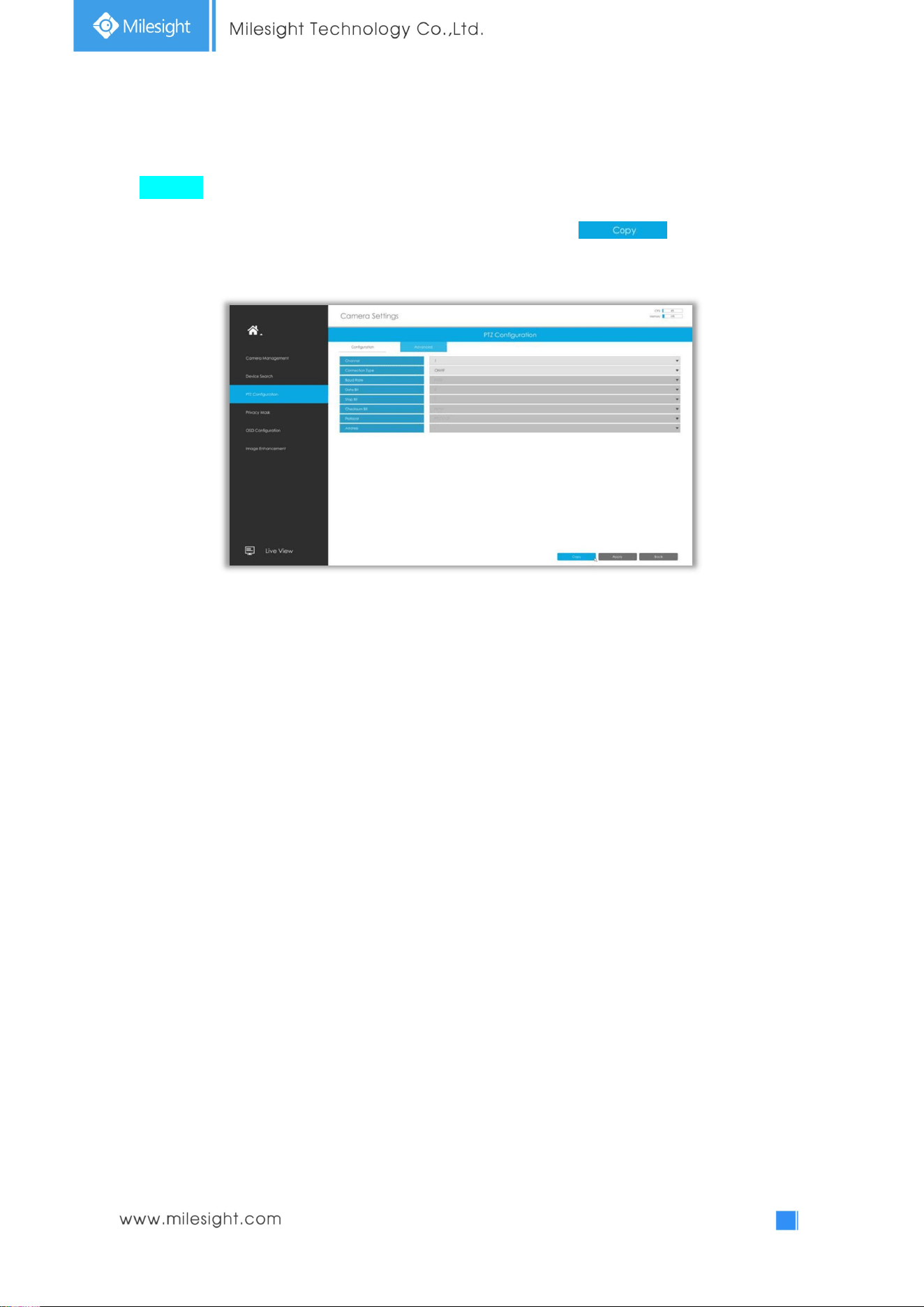
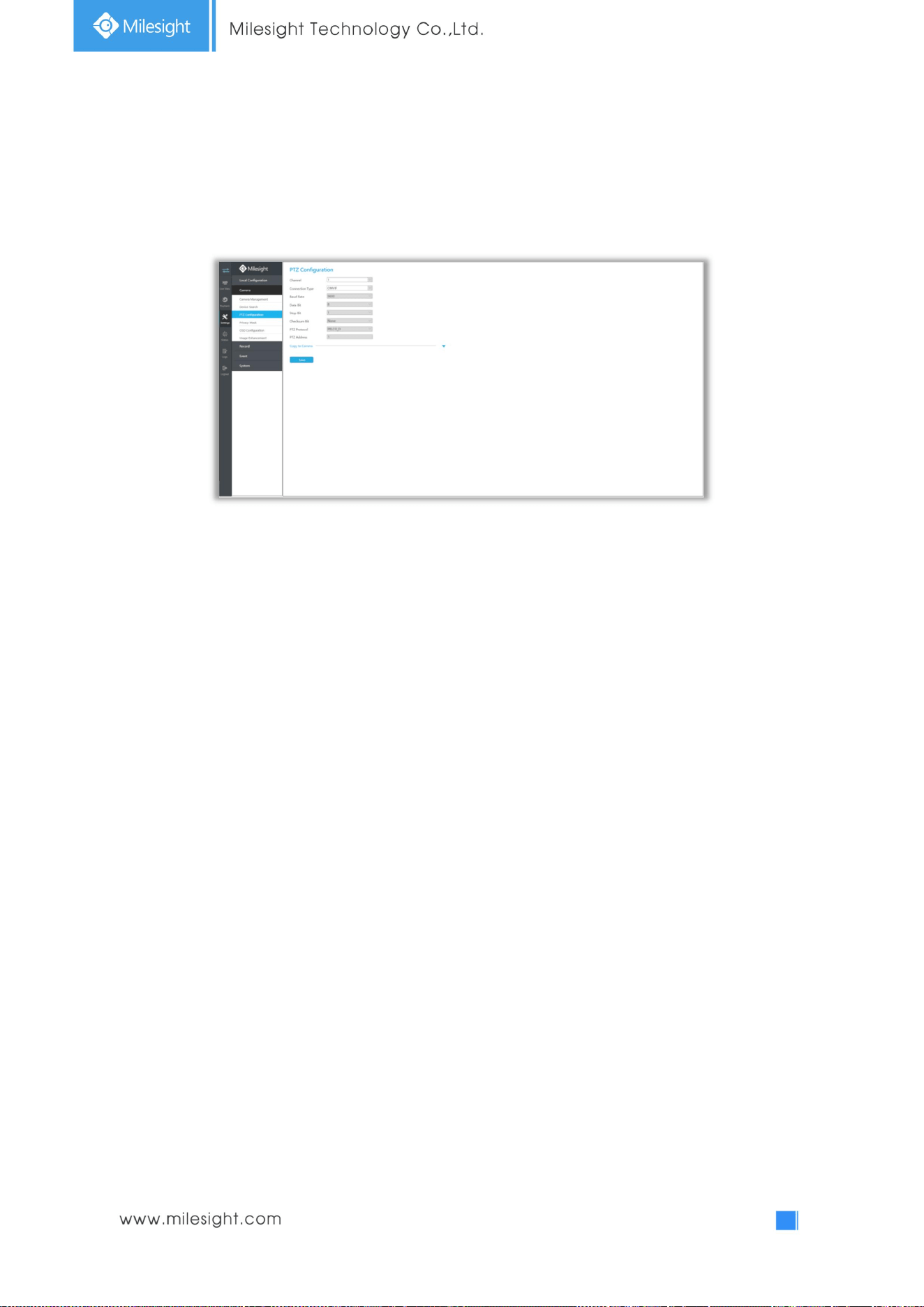
3.4.3 PTZ Configuration
Advanced
Choose a channel and set the PTZ parameters. Besides, you can click to copy the same
configuration to other channels.
Note:
1. Settings for a PTZ camera must be configured before it can be used. Make sure that the PTZ and
RS-485 of the NVR are connected properly.
2. The PTZ protocol and address of IP channel must be consistent with those of the PTZ decoder.
41
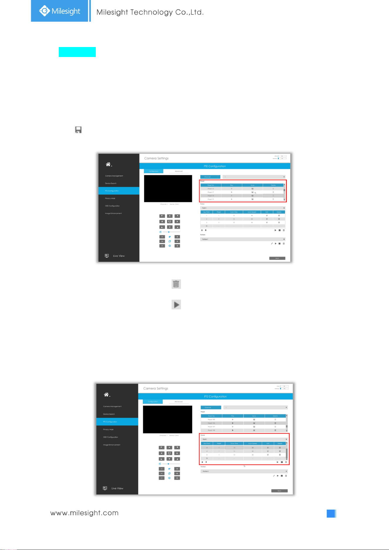
Configuration
[Preset]
Preset can be set to move your PTZ camera to a desired preset position. The preset position is the
preparation for Patrol.
Step1. Use the PTZ direction key to rotate the position of preset. Then choose a preset number and
click to save a preset position.
Step2. Choose a preset number and click to delete the preset position.
Step3. Choose a preset number and click to check the preset position.
[Patrol]
The camera will patrol according to the preset positions. The total time and patrol speed of the path is
variable.
Step1. Select a path. Up to 8 paths could be set.
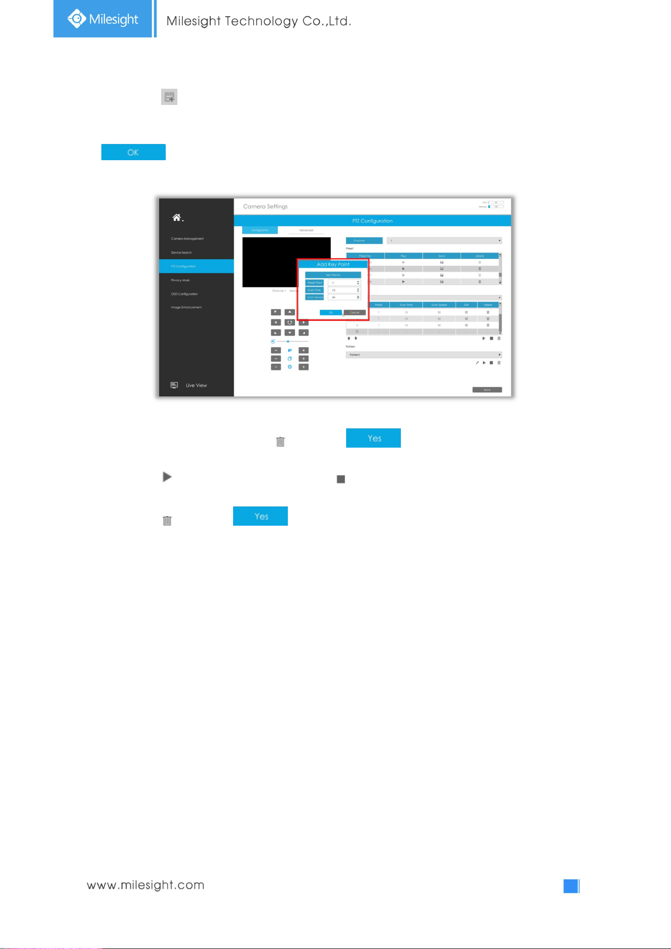
42
Step2. Click to add preset position (up to 48 positions could be added). Set the parameters of
preset positions, including preset position number, scan time and scan speed, then click
.
Step3. Select a preset position, click and select in the dialog box to delete it.
Step4. Click to preview the path patrol. Click to stop.
Step5. Click and select in the dialog box to delete all preset positions of the path
patrol.
Note:
1. The preset positions decide the patrol path, which will run according to numerical order of the
preset positions.
2. Scan time is how long the patrol stays on the preset position.
3. Scan speed is the rotate speed of speed dome from one preset position to the next.
43
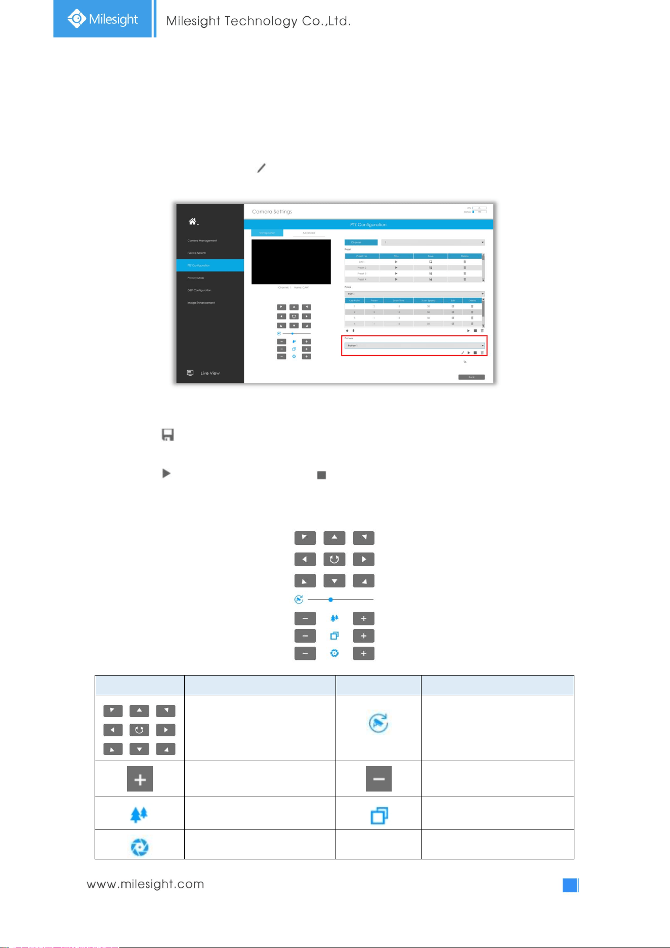
[Pattern]
The camera will patrol back and forth in a constant speed. There is only one start point and one end
point.
Step1. Select a pattern and click . Up to 4 patterns could be set.
Step2. Drag the mouse or click 8 direction keys by mouse to rotate PTZ.
Step3. Click to save the PTZ movement patterns.
Step4. Click to preview the pattern. Click to stop.
[PTZ Operation]
Icons Descriptions Icons Descriptions
PTZ direction control and auto
scan button
PTZ speed
Zoom +, Focus +, Iris + Zoom -, Focus -, Iris -
Zoom Focus
Iris
44
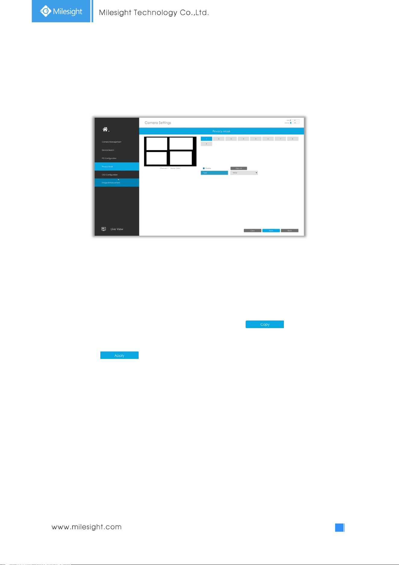
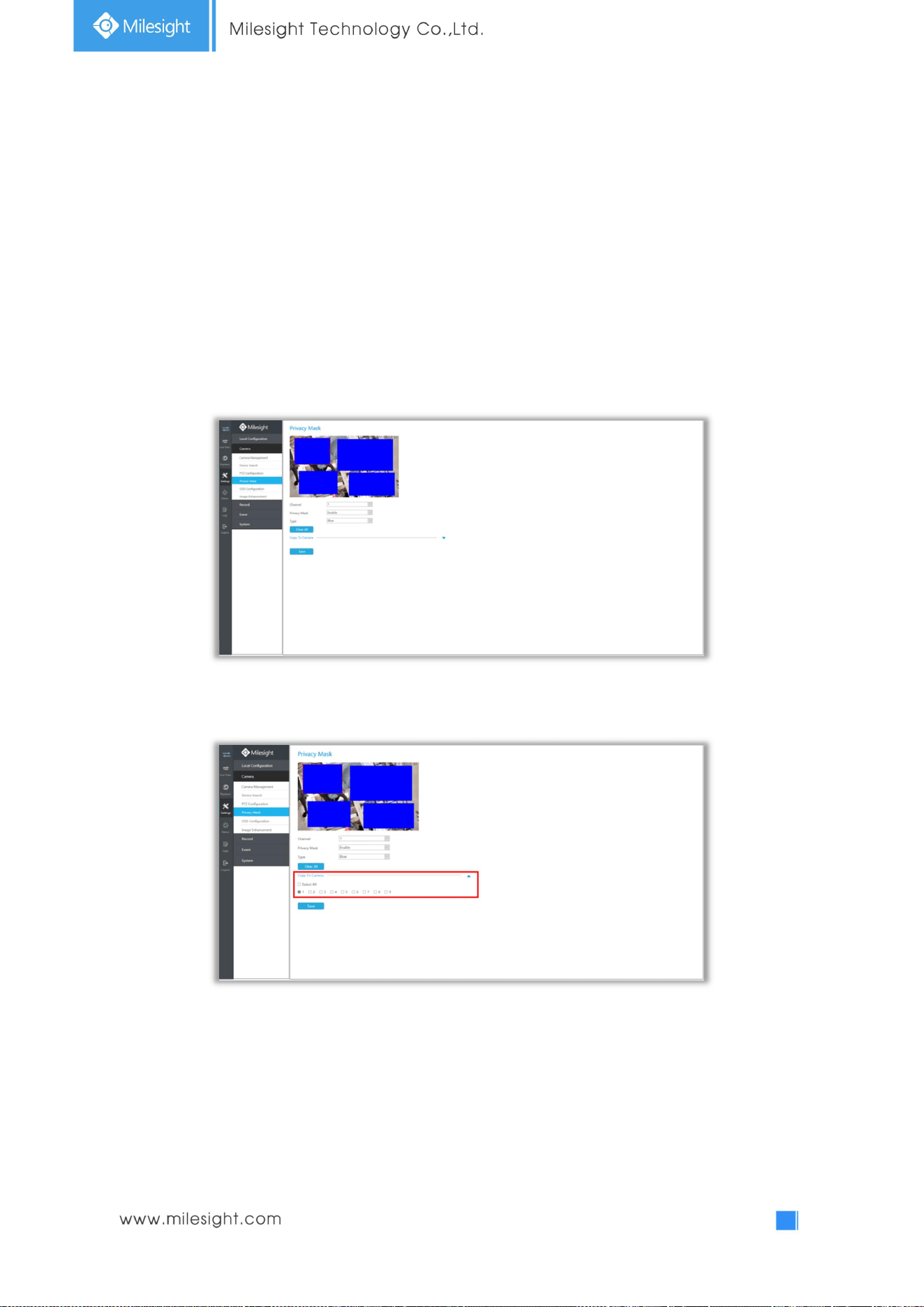
3.4.4 Privacy Mask
Milesight NVR supports to set privacy mask. It is used to cover some privacy area which is not proper
to appear on monitor.
You can add a privacy mask by following steps:
Step1. Select channel and enable privacy mask.
Step2. Set the privacy mask type and drag the mouse to select the area which is privacy on the live
window. You can add 4 areas at most.
Step3. Copy the privacy area to the other channels by clicking the “ ” button on the
bottom of the windows.
Step4. Select “ ” to save the settings.
45
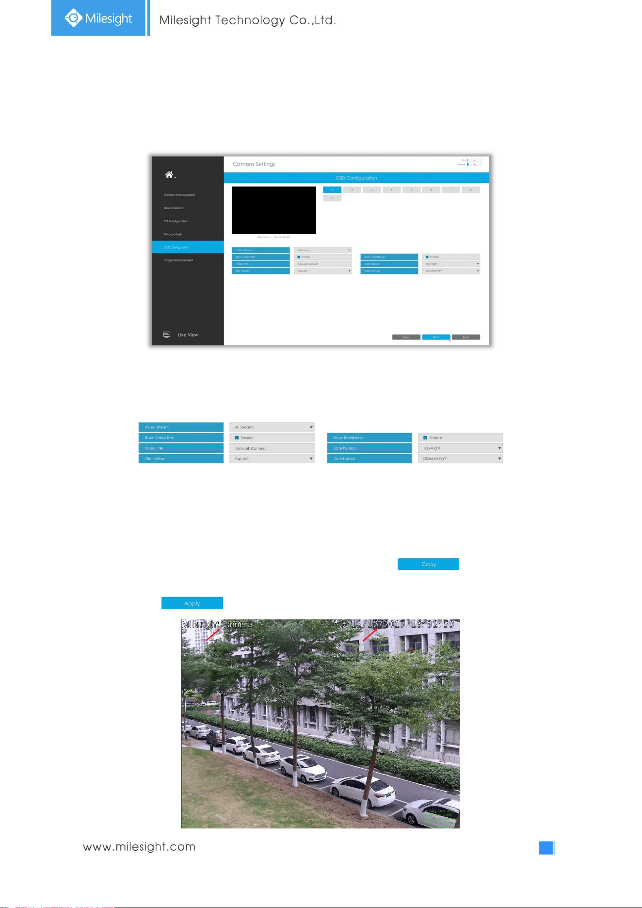
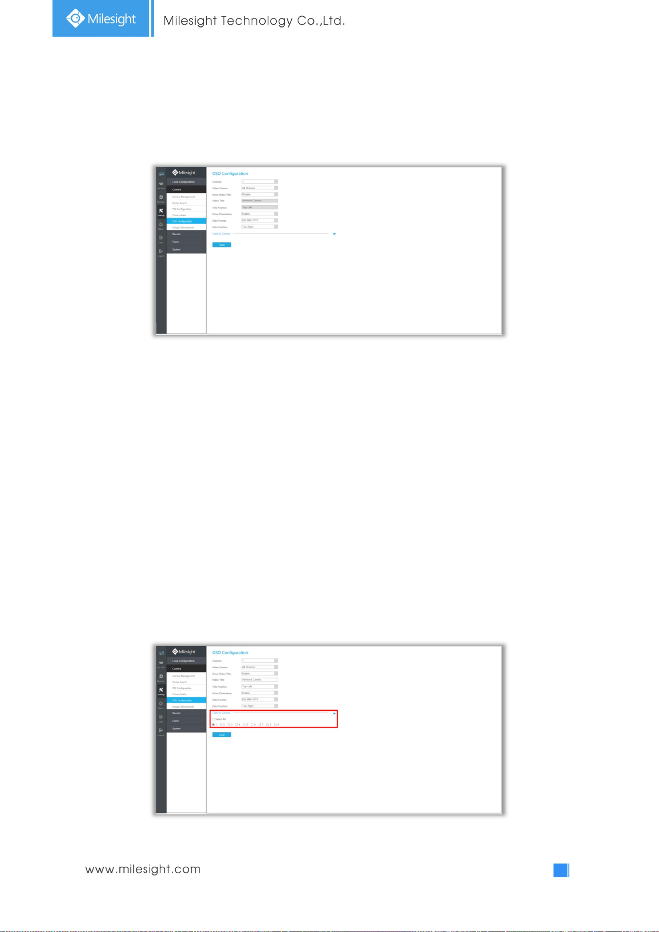
3.4.5 OSD Configuration
You can set OSD (On Screen Display) on NVR, and the OSD will be synchronized to Camera.
Step1. Select channel.
Step2. Select Video Stream, including All Streams, Primary Stream and Secondary Stream.
Step3. Enable video title and timestamp.
Show Video Title: Enable it and the video title will be shown on screen.
Title Position: Set the position for the video title: Top-Left or Top-Right.
Date Position: Set the position for the date: Top-Left, Top-Right, Bottom-Left or Bottom-Right.
Date Format: Set format for date: YYYY-MM-DD, MM/DD/YY or DD/MM/YYYY.
Step4. Copy the OSD settings to the other channels by clicking the “ ” button on the
bottom of the windows.
Step5. Select “ ” to save the settings.
46
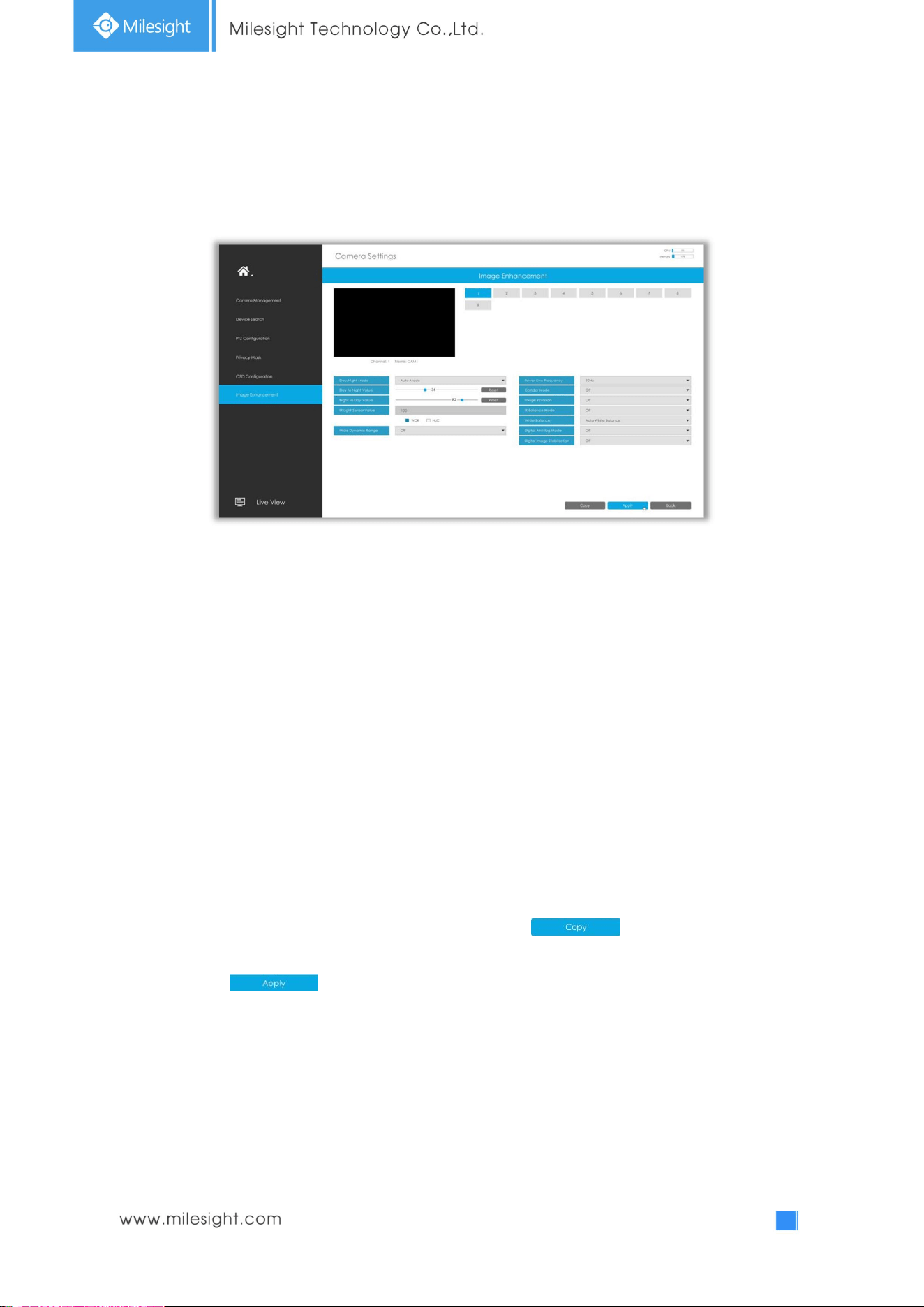
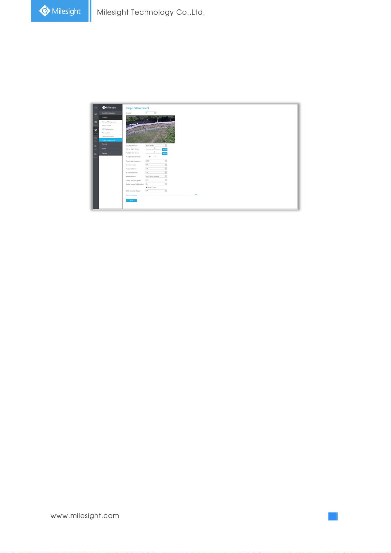
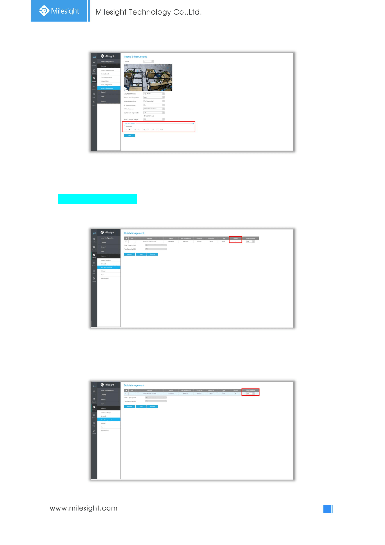
3.4.6 Image Enhancement
You can set Image Enhancement on NVR, and the configuration will be synchronized to Camera.
Step1. Select channel.
Step2. Set the configuration.
Day/Night Mode: Set the Day/Night mode for the channel.
Day to Night Value: Set the Minimum illumination intensity to trigger Night Mode.
Night to Day Value: Set the Maximum illumination intensity to trigger Day Mode.
IR Light Sensor Value:Shows the current value of IR light sensor.
Power Line Frequency: 50Hz and 60Hz are available.
Corridor Mode: Set corridor mode.
Image Rotation: Set image rotation.
IR Balance Mode:Turn on to avoid IR overexposure.
White Balance: Choose a white balance mode for the channel.
Digital Anti-fog Mode: Set the Anti-fog function on and off.
WDR/HLC: Click to configure Wide Dynamic Range or High Light Control.
Step3. Copy the image settings to other channels by clicking on the bottom of the
windows.
Step4. Select to save the settings.
47
3.5 Record
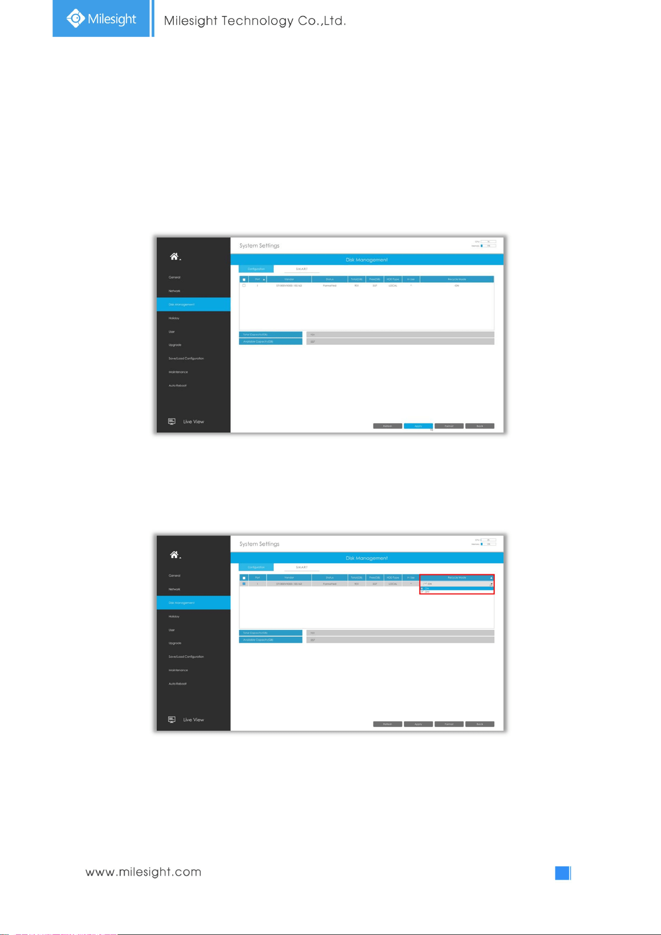
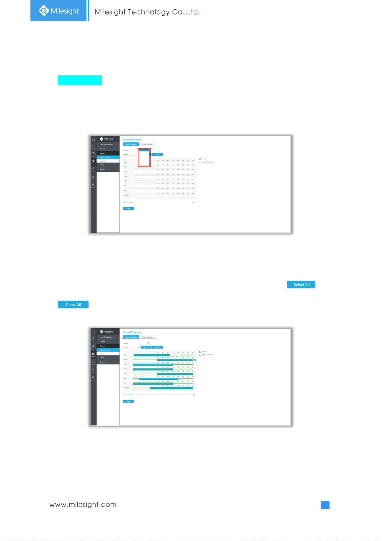
3.5.1 Preparation for Record
Step1. Ensure your NVR has been installed and the HDD has been initialized, please check it on
“Settings” -> ”Disk Management” interface.
Step2. Ensure that the HDD has sufficient storage space.
Double click the Recycle Mode and select it to ON.
48
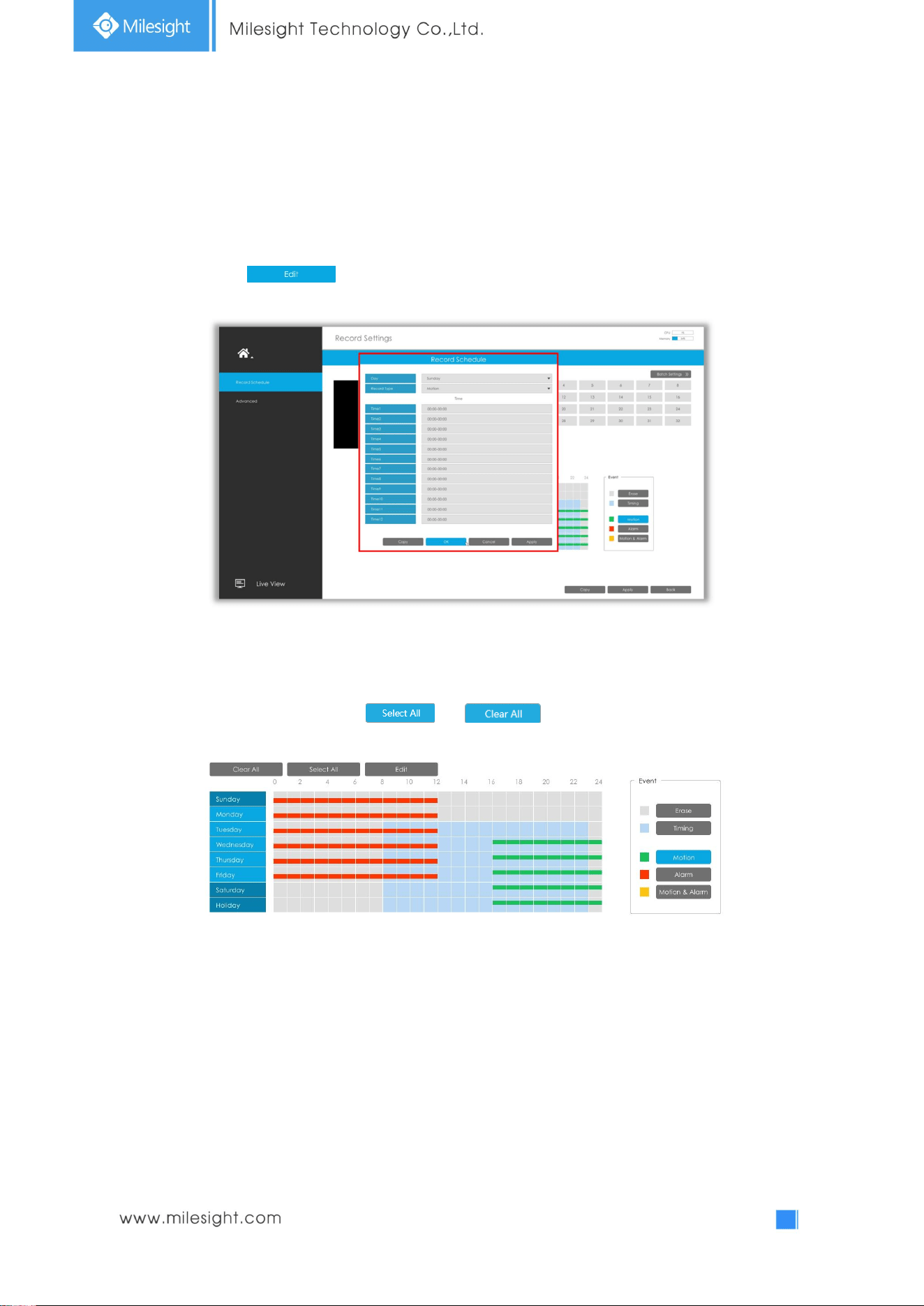
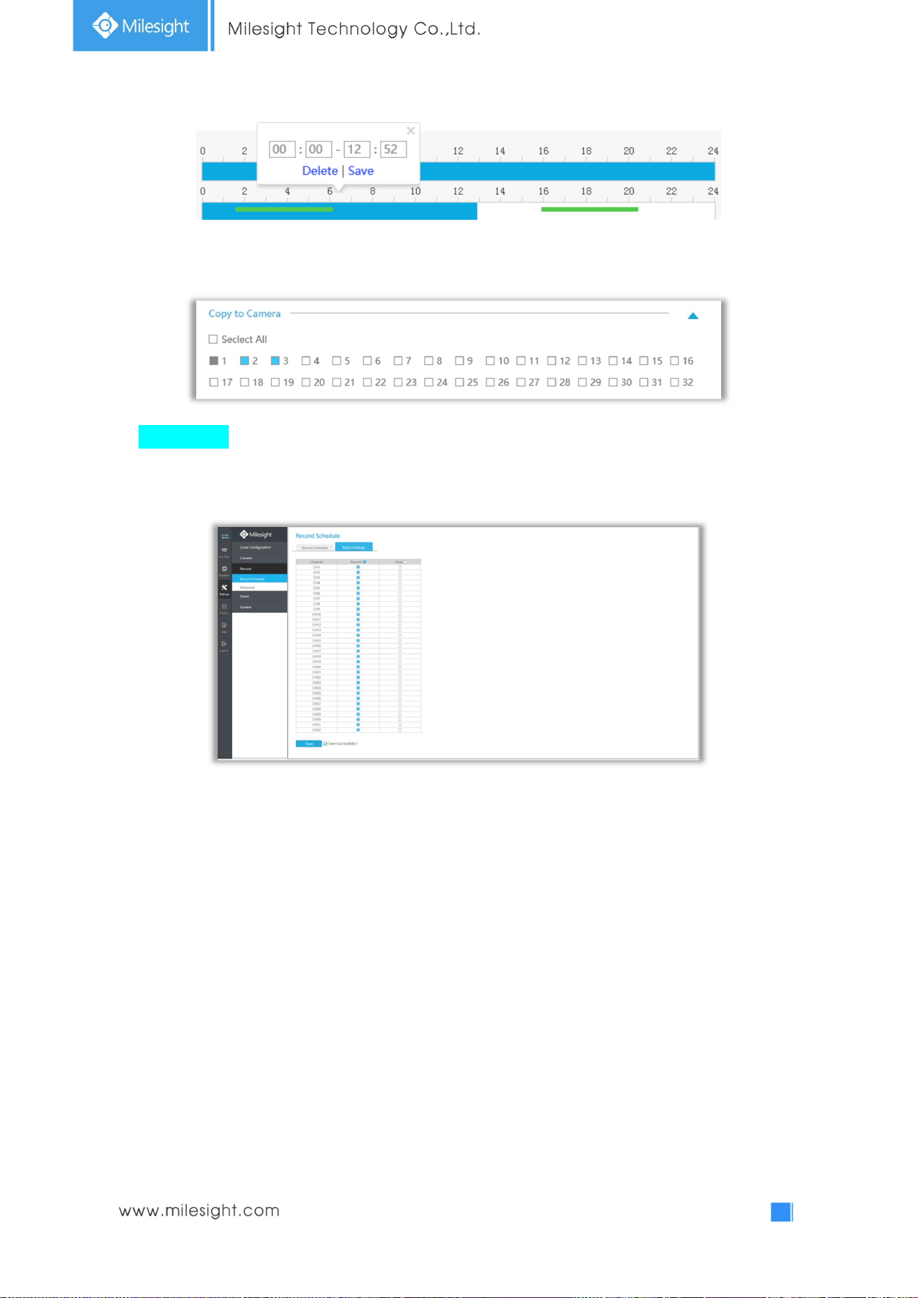
3.5.2 Record Shedule
Step1. Select channel.
Step2. Set record schedule.
Method 1: Click to edit schedule. Select Day, Record Type and Time to finish editing.
Method 2: Select operation type: Timing, Motion, Alarm, Motion&Alarm or Erase. Then drag a square
in the time table to set record effective time. It is convenient for you to set all or clear all
corresponding schedule by clicking or .
49
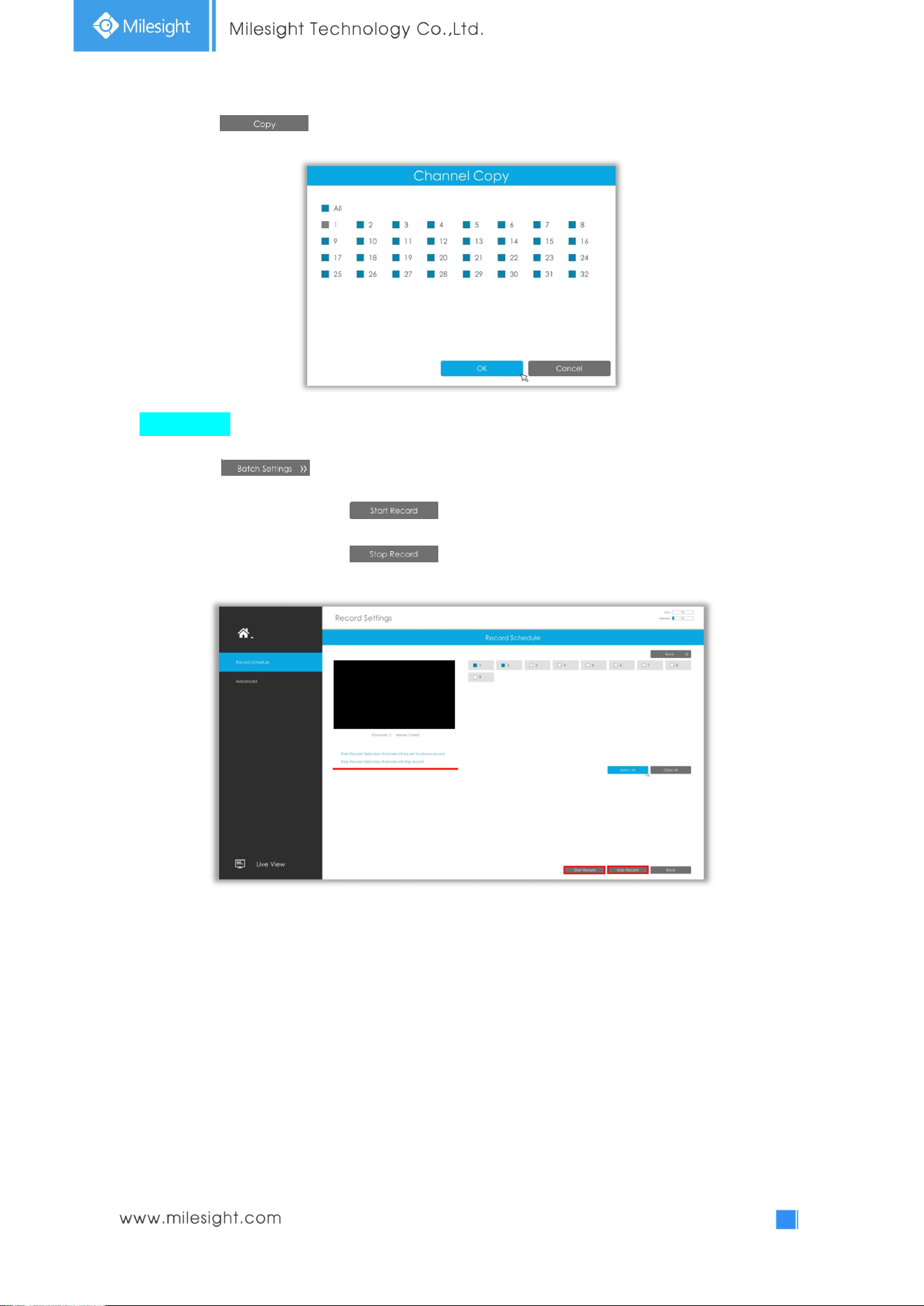
Step3. Click to copy the same record configuration to other channels.
Batch Settings
Step1. Click to enter Batch Settings interface.
Step2. Select channels and click to start always record.
Step3. Select channels and click to stop record.
50
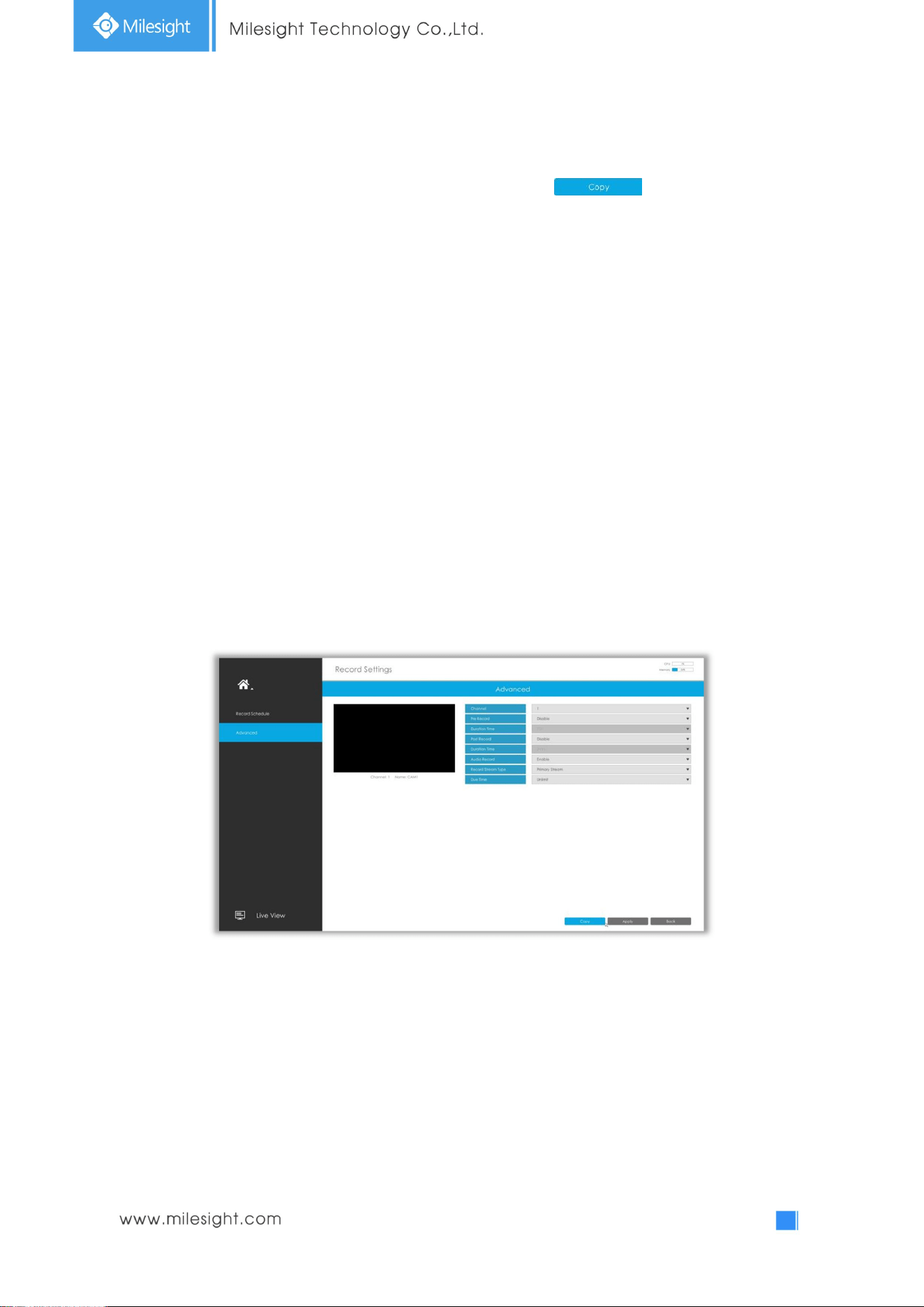
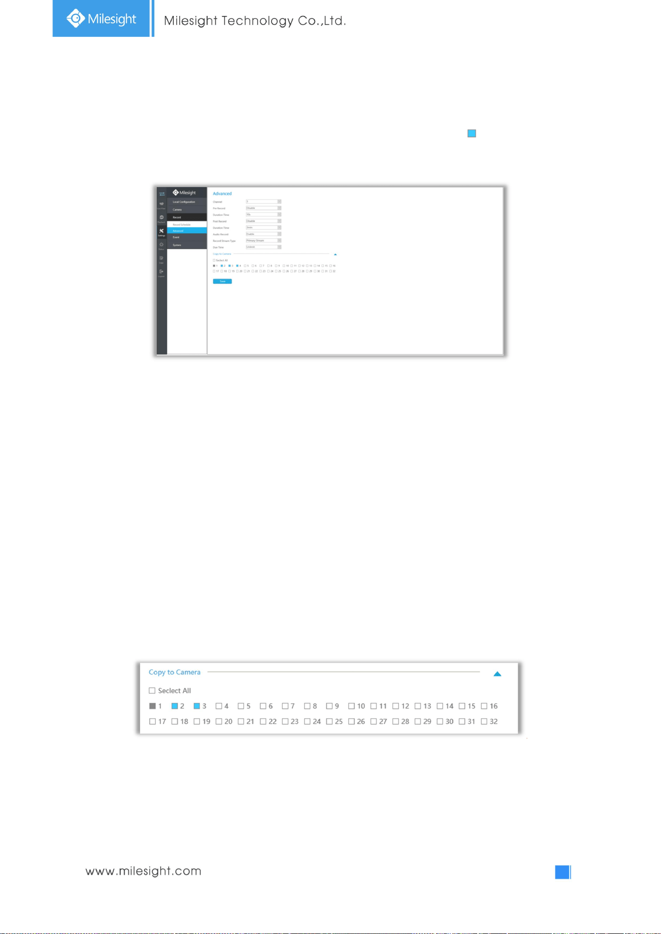
3.5.3 Advanced
Make advanced configuration for selected channels. Click to copy the same
configuration to other channels..
Channel: Select the channel which will be set.
Pre Record : Enable/Disable pre-record. It will start recording before the event is triggered.
Duration Time: Event pre-record duration time.
Post Record:Enable/Disable post record. It will keep recording after the event is over.
Duration Time: Event post-record duration time.
Audio Record: Select to record audio or not.
Record Stream Type: Select Main stream or sub stream for record.
Due Time: Set the due time of recording files.
51
3.6 Event Settings
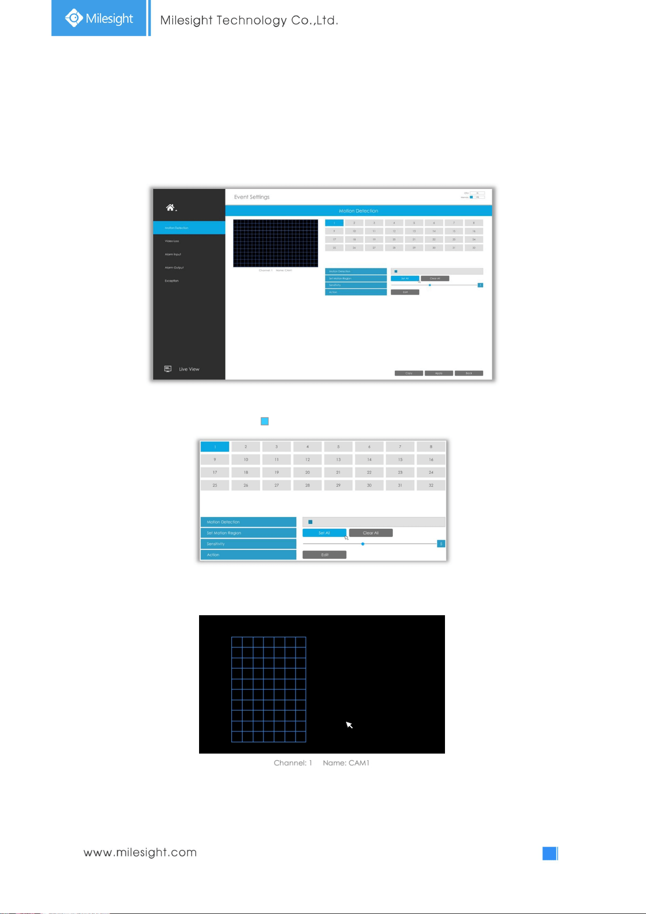
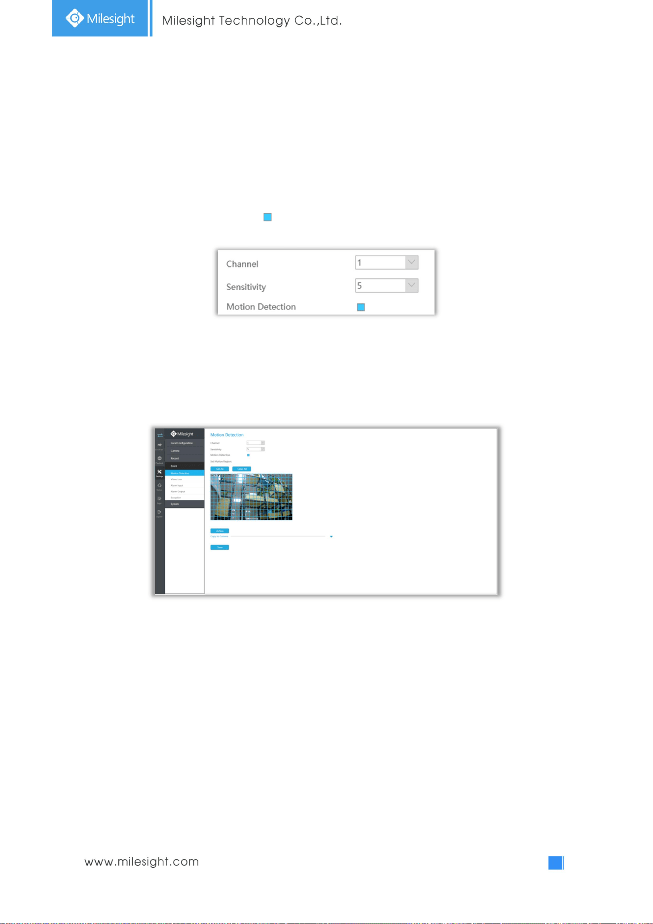
3.6.1 Motion Detection
Step 1. Enable Motion Detection.
Select channel , Sensitivity and click to enable Motion Detection.
Step2: Set the area for triggering motion detection.
You can set the area by dragging a square on live view window.
Note: The motion detection area will be synchronized to Camera.
52
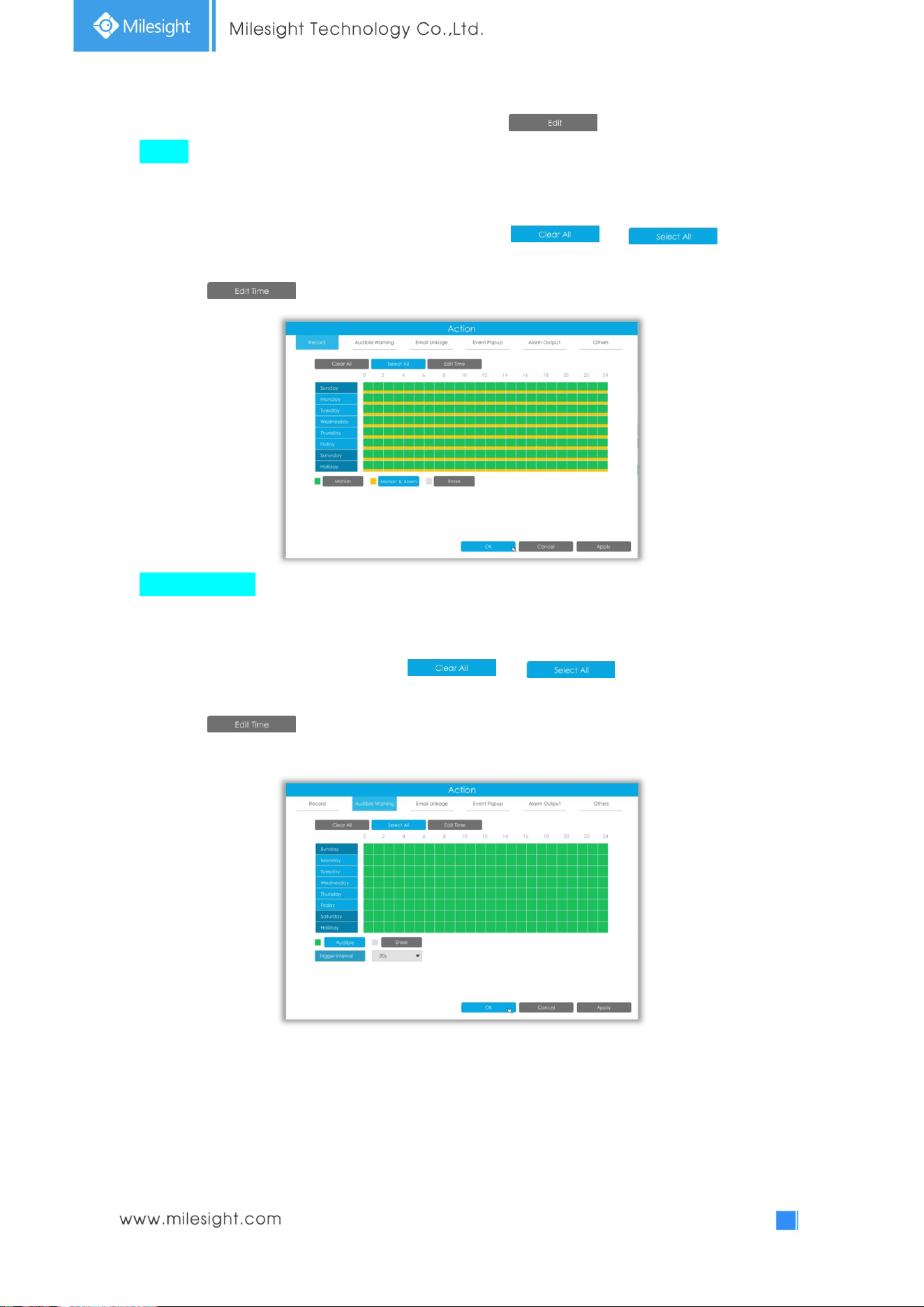
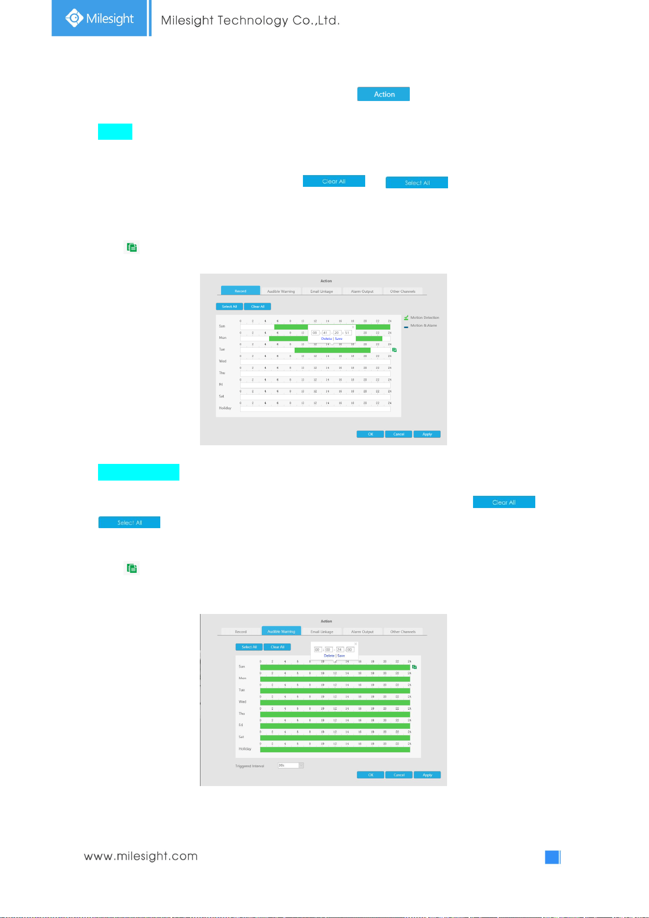
Step 3. Set Action for motion detection alarm by clicking .
Record: Record when alarm is triggered.
The user can set effective schedule as following two ways:
① Select the operation type: Motion, Motion&Alarm or Erase. Then drag a square on the time table
for time setting, it will be more convenient by clicking or to set or
clear all time settings.
② Click to edit record effective time manually.
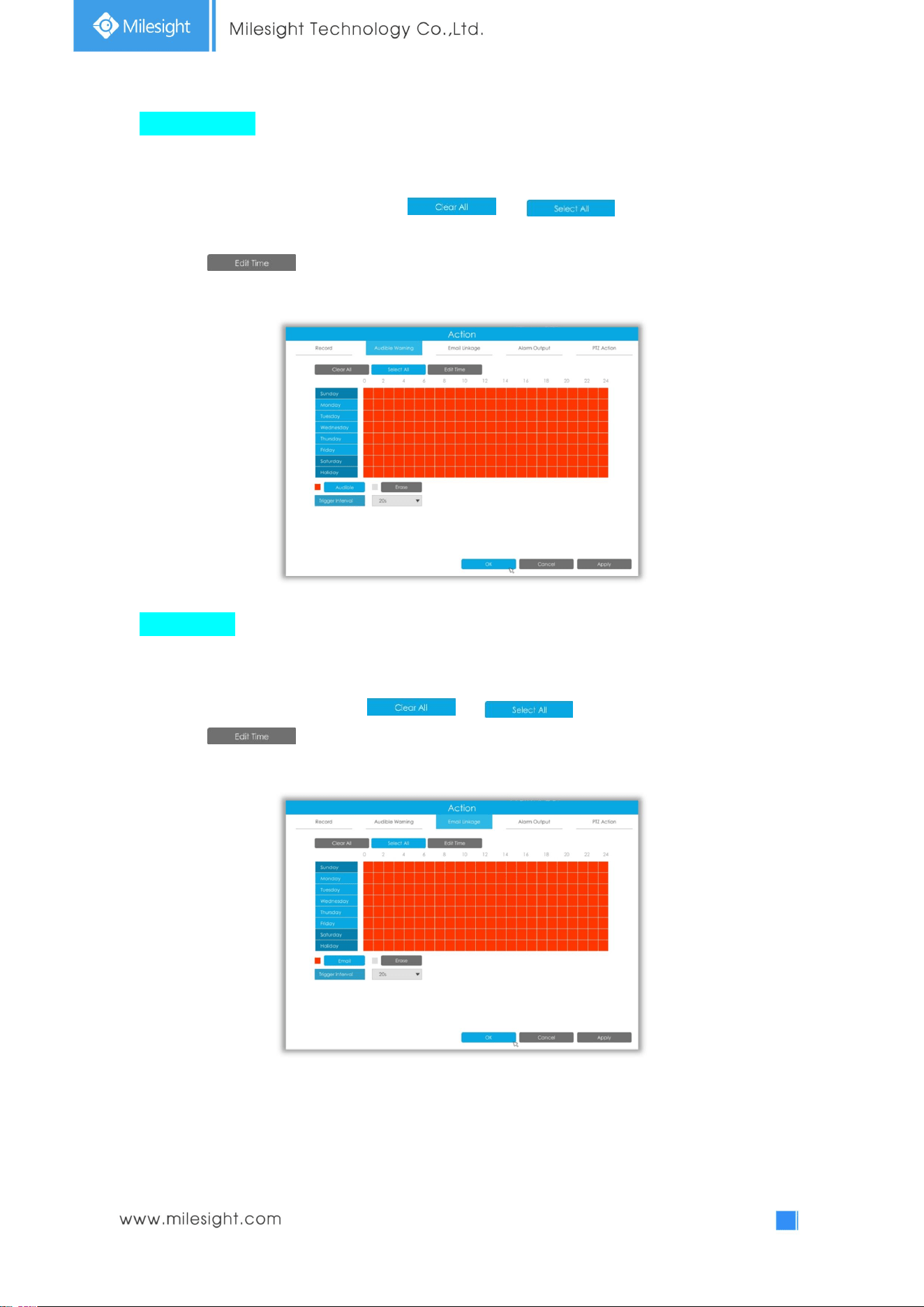
Audible Warning: NVR will trigger an audible beep when motion is detected.
The user can set effective schedule as following two ways:
① Select the operation type: Audible or Erase. Then drag a square on the time table for time setting,
it will be more convenient by clicking or to set or clear all time
settings.
② Click to edit record effective time manually.
Trigger Interval: The effective interval between two actions when event triggered.
53
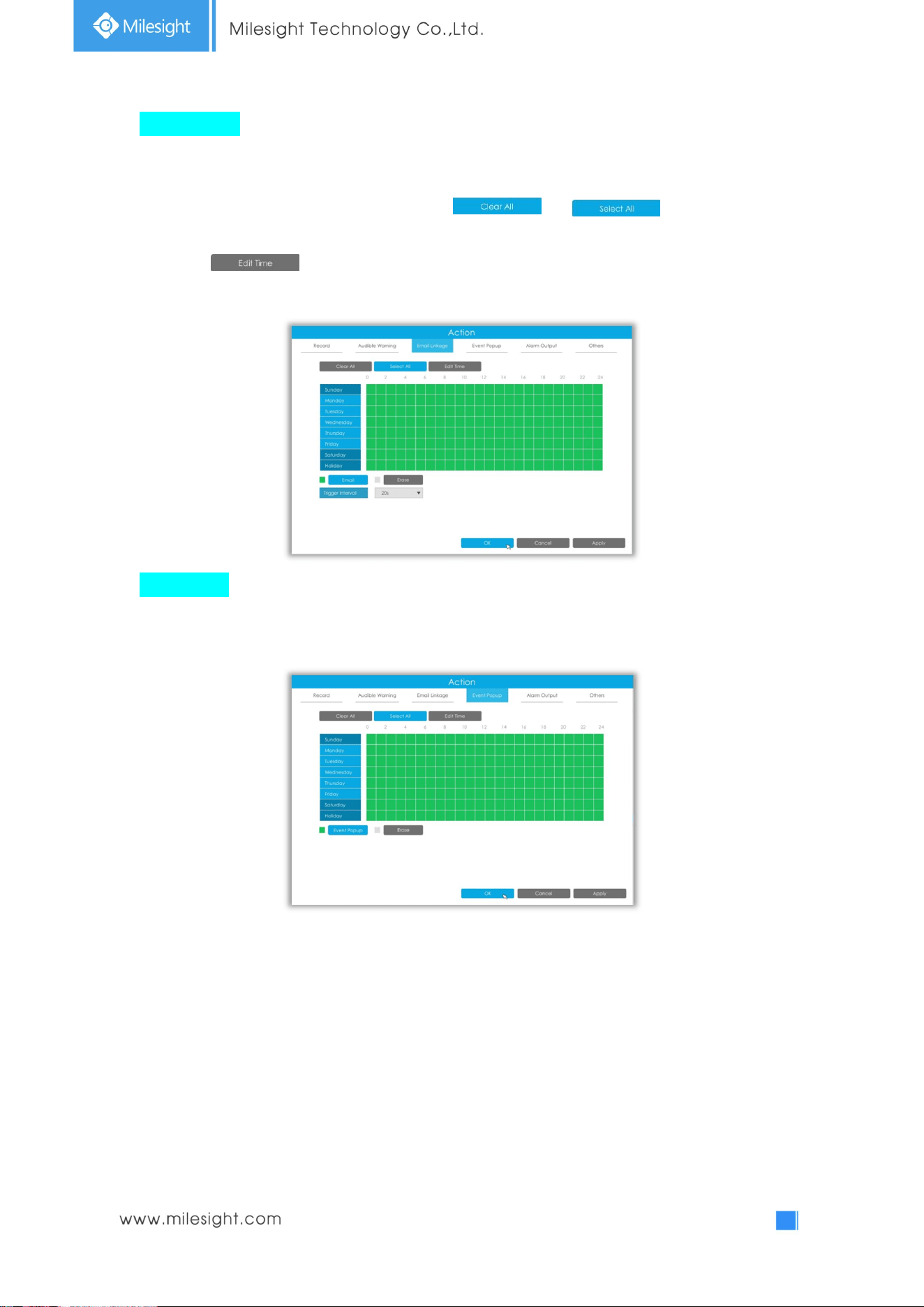
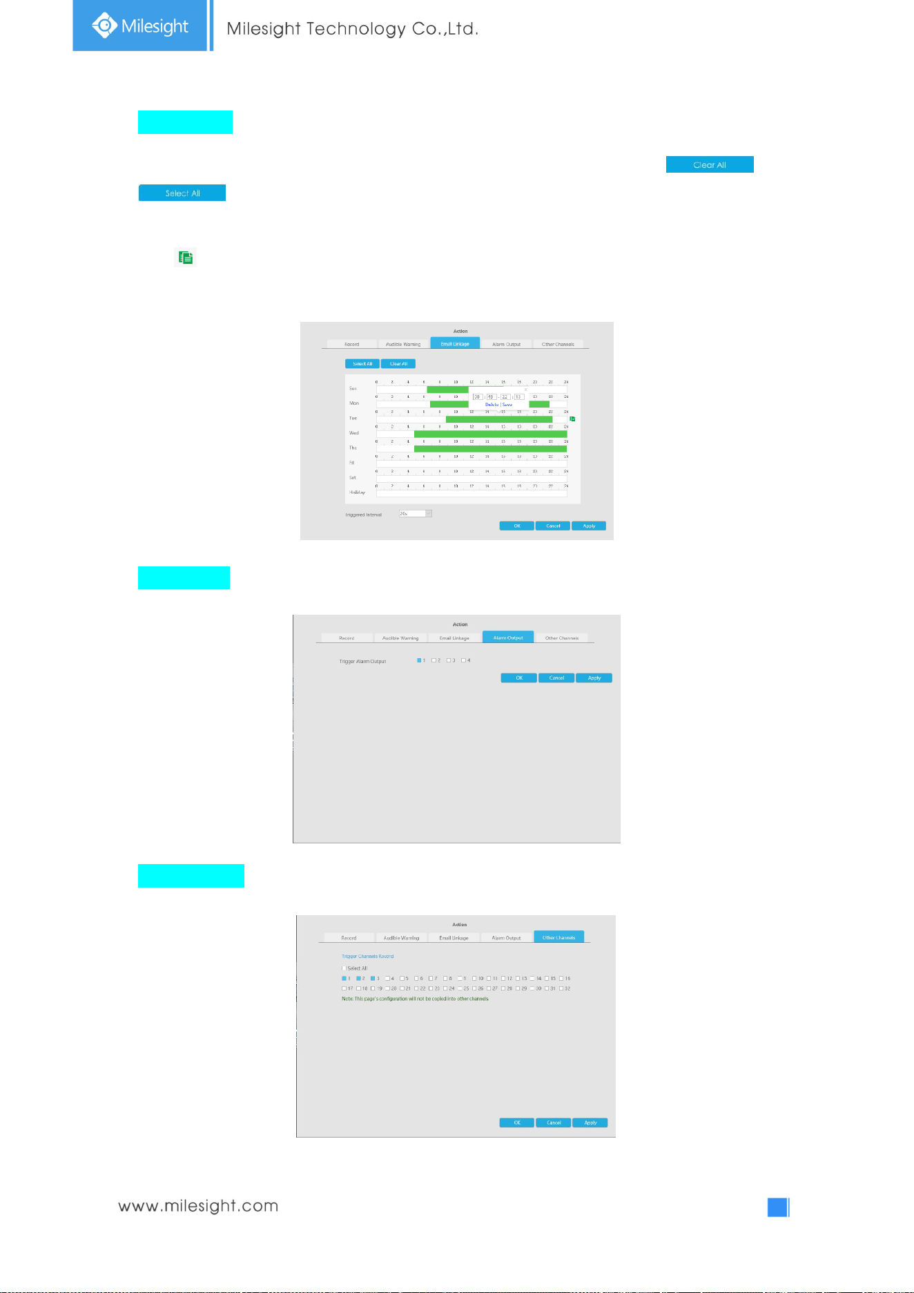
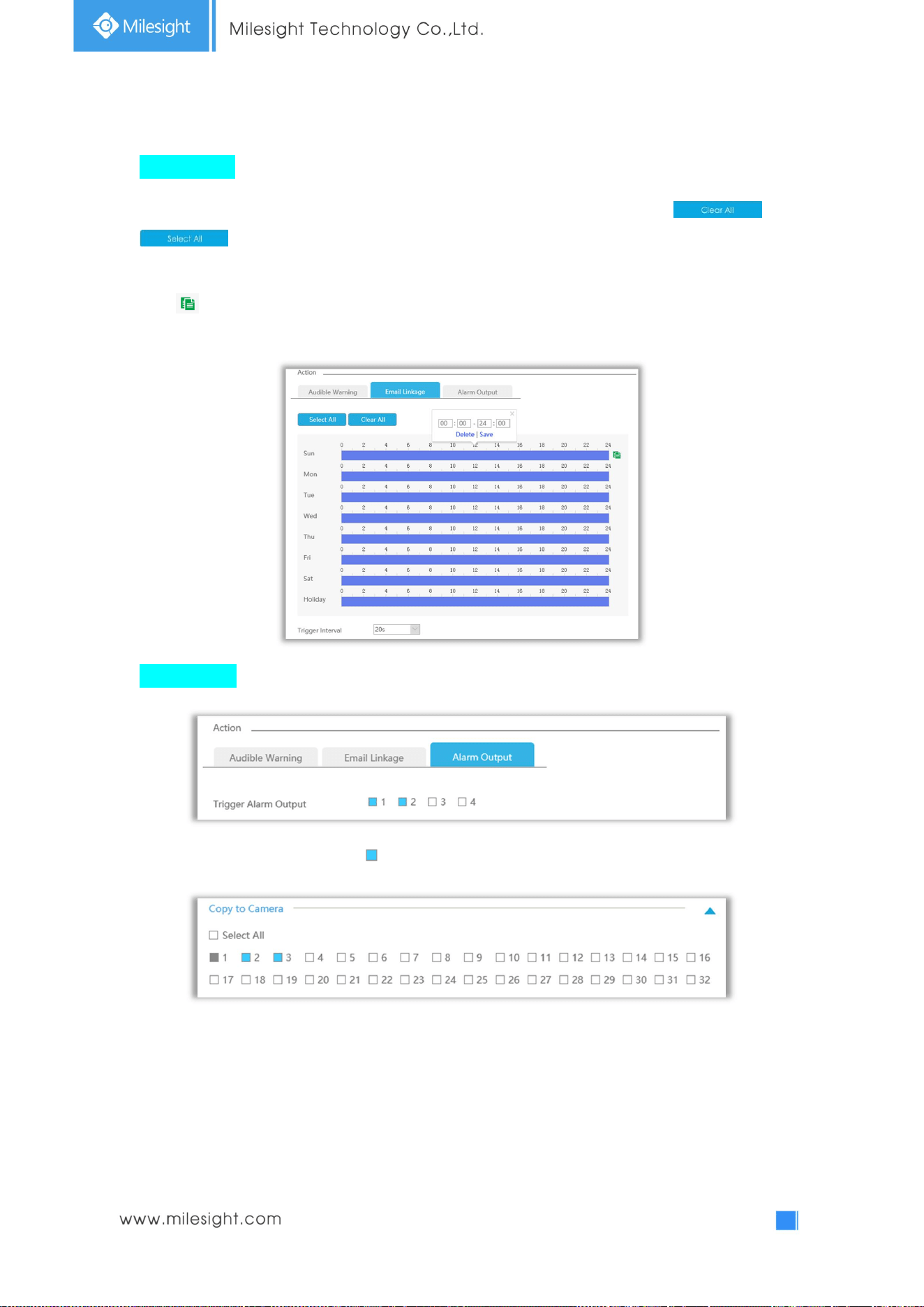
Email Linkage: NVR will send an email to the address you set before.
The user can set effective schedule as following two ways:
① Select the operation type, Email and Erase. Then drag a square on the time table for time
setting, it will be more convenient by clicking or to set or clear all
time settings.
② Click to edit effective time manually.
Trigger Interval: The effective interval between two actions when event triggered.
Event Popup:Trigger alarm screen popup to full screen when alarm is triggered.
You can set display duration time of all triggered channel in ‘Settings’->’General’->’Event Popup
Duration Time’. Then triggered channel will be shown one by one as duration time.
54
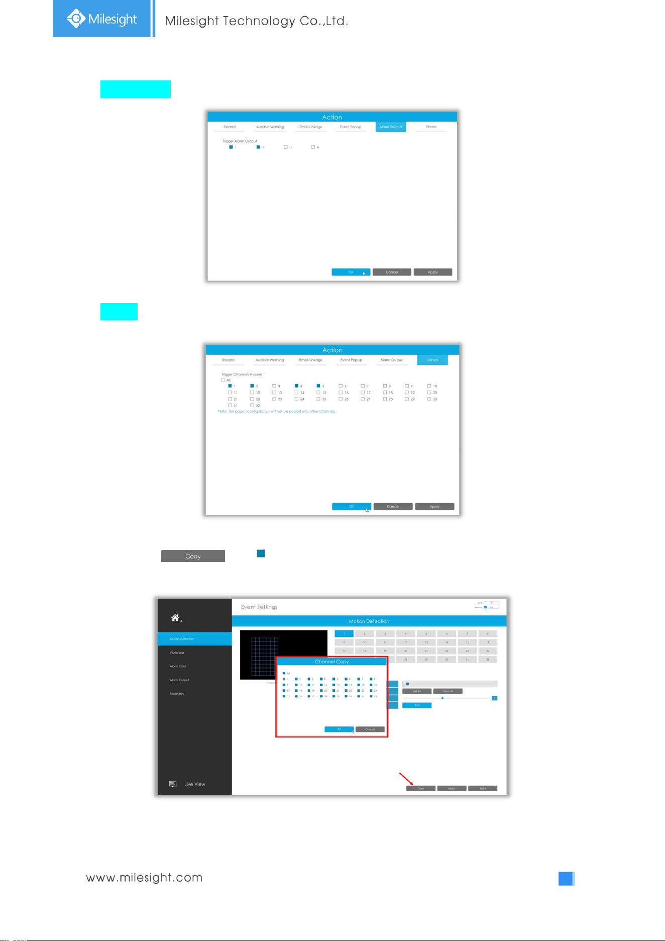
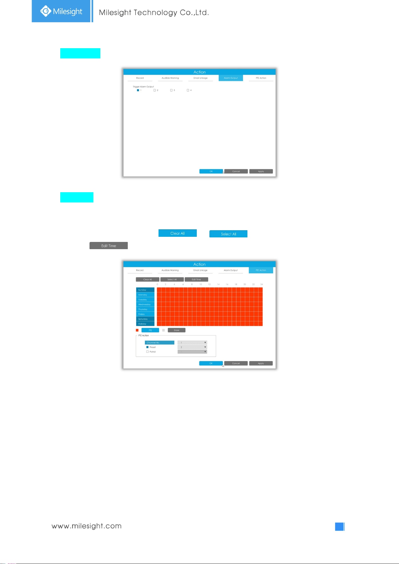
Alarm Output: Trigger alarm output when alarm is triggered.
Others: Trigger other channels record when alarm is triggered.
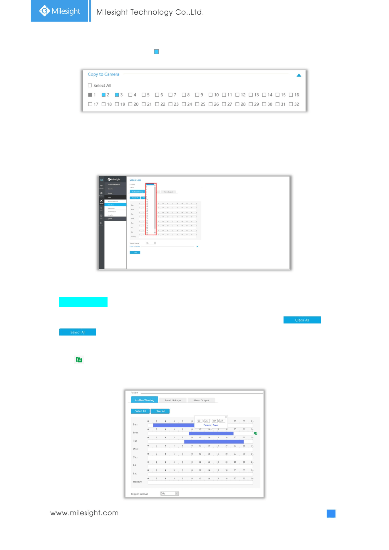
Step 5. Click and to copy the same configuration to other channels.
55
3.6.2 Video Loss
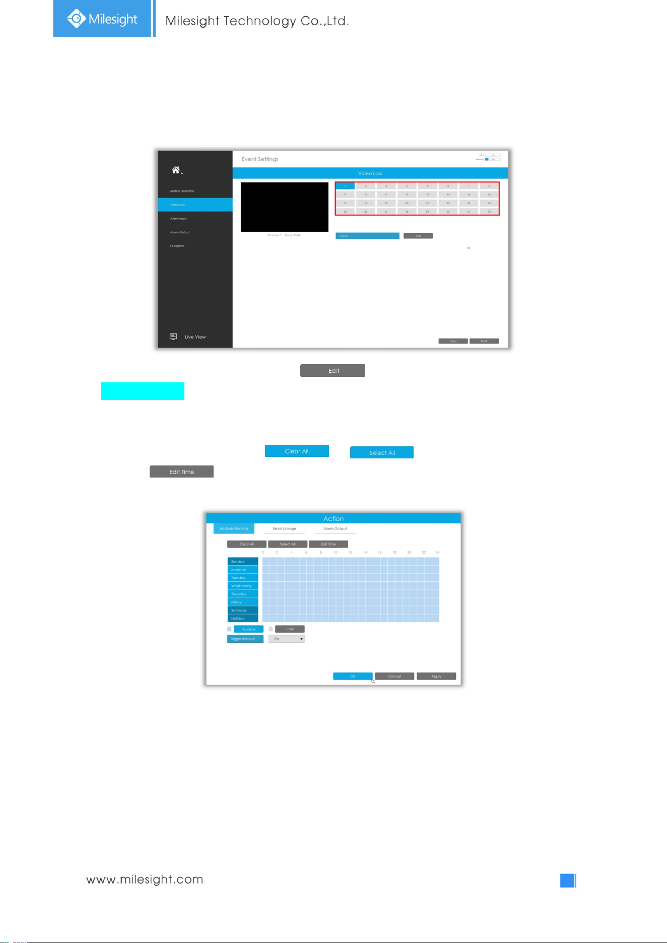
Step1. Select a channel.
Step2. Set Action for video loss by clicking .
Audible Warning: NVR will trigger an audible beep when motion is detected.
The user can set effective schedule as following two ways:
① Select the operation type: Email or Erase. Then drag a square on the time table for time setting, it
will be more convenient by clicking or to set or clear all time settings.
② Click to edit effective time manually.
Trigger Interval: The effective interval between two actions when event triggered.
56
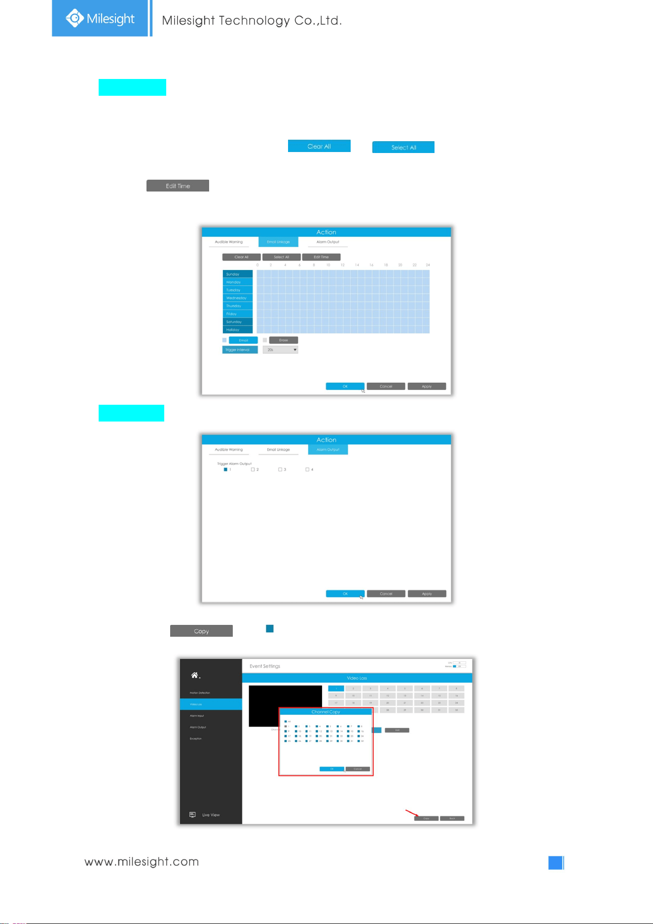
Email Linkage: NVR will send an email to the address you set before.
User can set effective schedule as following two ways:
① Select the operation type: Email or Erase. Then drag a rectangle on the time table for time setting,
it will be more convenient by clicking or to set or clear all time
settings.
② Click to edit record effective time manually.
Trigger Interval: The effective interval between two actions when event triggered.
Alarm Output: Trigger alarm output when alarm is triggered.
Step 3. Click and to copy the same configuration to other channels.
57
3.6.3 Alarm Input
Alarm Input function is supported by UI-5016-B, UI-7016-B, UI-7032-B, UI-8032-B, UI-5016-PB, and
UI-7032-PB.
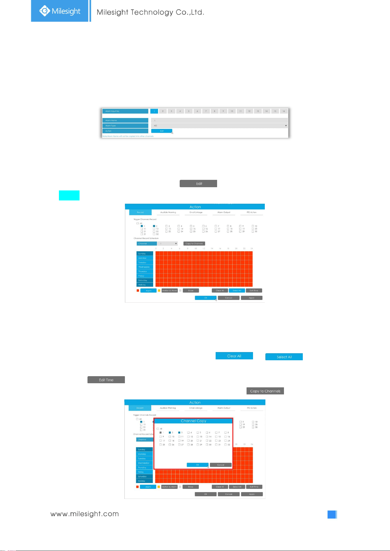
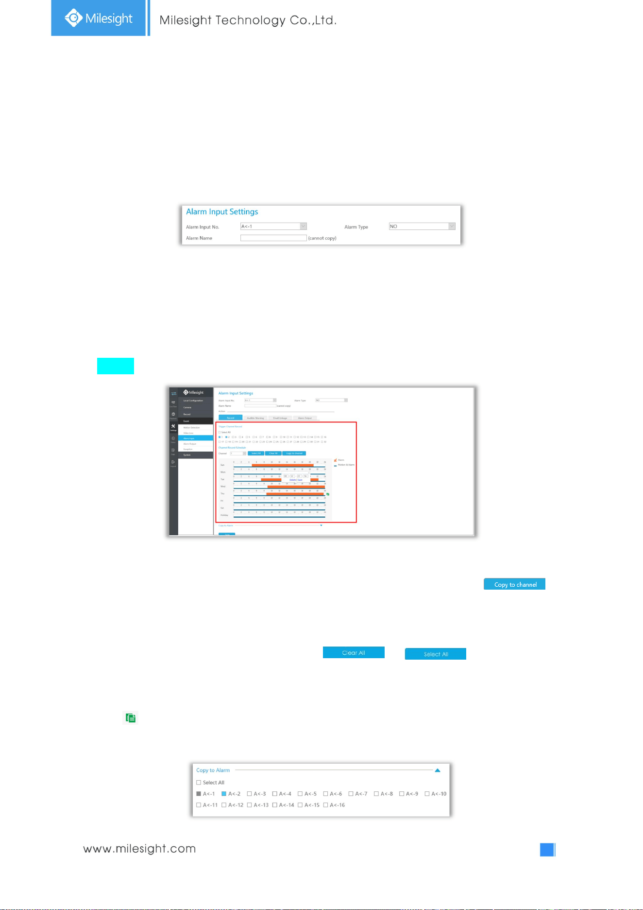
Step1. Set Alarm input Number, Alarm Name and Alarm Type.
Alarm Input No.: The channel which has input signal.
Alarm Name: Set a name for the alarm.
Alarm Type: Choose NO or NC alarm type for the alarm.
Step2. Set action for alarm input by clicking .
Record: Startrecording when alarm is triggered.
Trigger Channel Record:Trigger selected channels to record when alarm is triggered.
Channel Record Schedule: Select channel and set corresponding schedule. User can set effective
schedule as following two ways:
① Select the operation type: Alarm, Motion&Alarm or Erase. Then drag a square on the time table
for time setting, it will be more convenient by clicking or to set or
clear all time settings.
② Click to edit record effective time manually.
Copy to Channels: Copy record schedule to other channels by clicking .
58
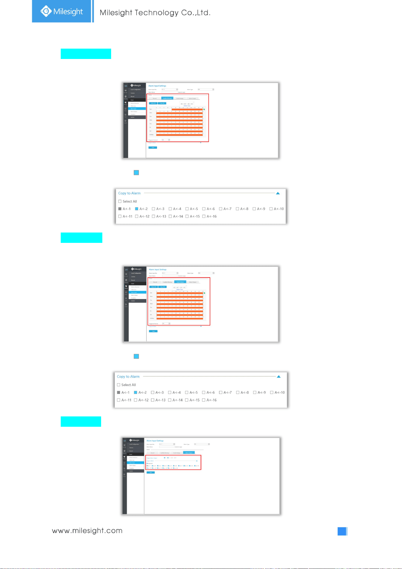
Audible Warning: NVR will trigger an audible beep when alarm is triggered.
User can set effective schedule as following two ways:
① Select the operation type: Audible or Erase. Then drag a square on the time table for time setting,
it will be more convenient by clicking or to set or clear all time
settings.
② Click to edit effective time manually.
Trigger Interval: The effective interval between two actions when event triggered.
Email Linkage: NVR will send an email to the address you set before.
User can set effective schedule as following two ways:
① Select the operation type: Email or Erase. Then drag a square on the time table for time setting, it
will be more convenient by clicking or to set or clear all time settings.
② Click to edit effective time manually.
Trigger Interval: The effective interval between two actions when event triggered.
59
Alarm Output: Trigger alarm output when alarm is triggered.
PTZ Action: Trigger PTZ action when alarm is triggered. PTZ action includes Preset and Patrol.
User can set effective schedule as following two ways:
① Select the operation type: Email or Erase. Then drag a square on the time table for time setting, it
will be more convenient by clicking or to set or clear all time settings.
② Click to edit record effective time manually.
60
3.6.4 Alarm Output
Alarm Output function is supported by UI-5016-B, UI-7016-B, UI-7032-B, UI-8032-B, UI-5016-PB, and
UI-7032-PB.
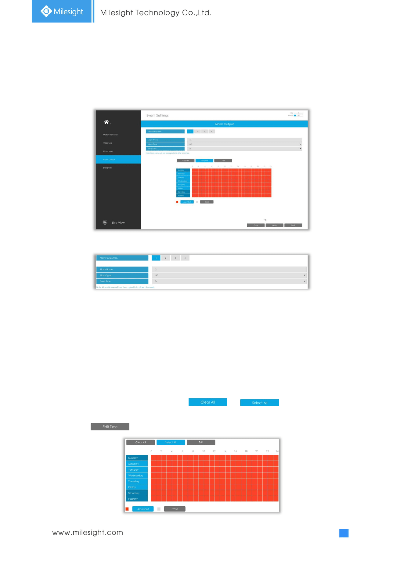
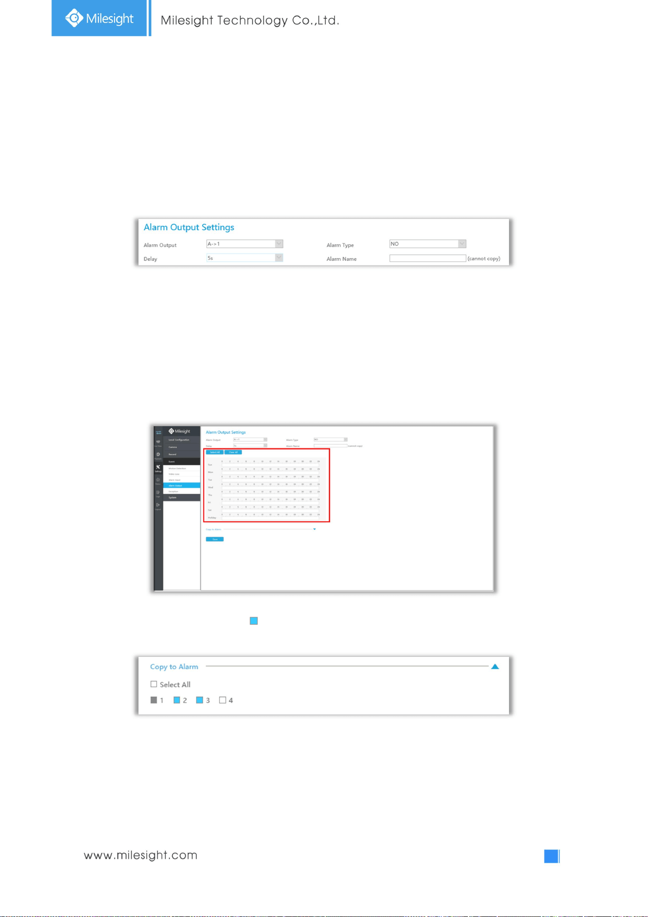
Step 1. Set Alarm output channel, Alarm Name, Alarm Type and Record Channels.
Alarm Output No.: The channel which will output the alarm signal.
Alarm Name: Set a name for the alarm.
Alarm Type: Choose NO or NC alarm type for the alarm.
Dwell Time: The output time for alarm. If the output alarm lasts too long, you can select the Manually
Clear to stop it.
Step2. Select effective Time for alarm output.
The user can set effective schedule as following two ways:
① Select the operation type: AlarmOut or Erase. Then drag a square on the time table for time
setting, it will be more convenient by clicking or to set or clear all time
settings.
② Click to edit record effective time manually.
61
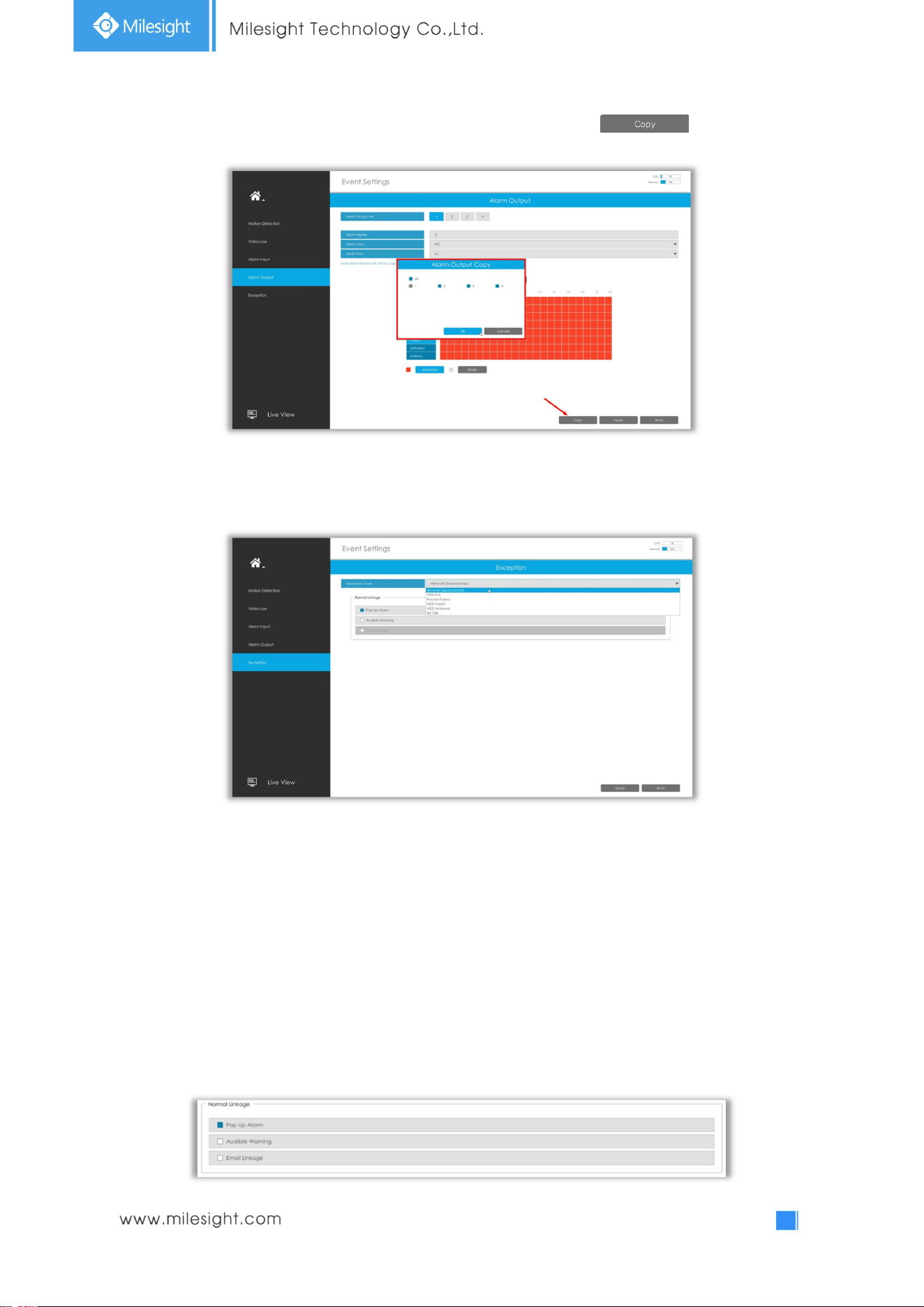
Step3: Copy alarm output settings to other output interface by clicking .
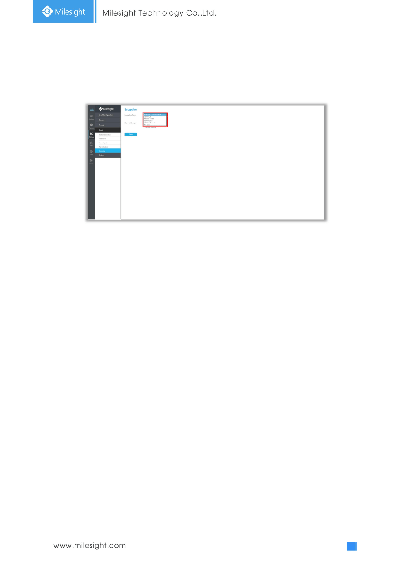
3.6.5 Exception
Step1. Select Exception Type.
Network Disconnected: Loss of network.
HDD Full: HDD full. It usually happens when recycle Mode is OFF.
Record Failed: Recording fails, including HDD Failed, HDD Full and so on.
HDD Failed: Failed to recognize HDD.
HDD Unformat: HDD is unformat.
No Disk: There is no HDD.
Step2. Select normal linkage includes Pop up Alarm, Audible Warning and Email Linkage.
Pop Up Alarm:A window will be popped up in Live View if an alarm is triggered.
Audible Warning: NVR will trigger an audible beep.
Email Linkage: An alarm Email will be sent if an alarm is triggered.
62
3.7 Settings
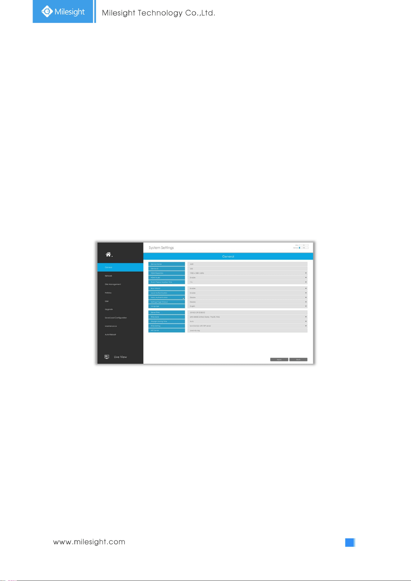
3.7.1 General
It is to setup the general parameters of NVR, including Device Name, Device ID, HDMI Resolution,
Language, System time, etc.
Event Popup Duration Time: The display duration time for Motion Detection popup screen.
Boot Wizard: Enable it to pop up boot wizard after rebooting.
Local Authentication: Enable it to authenticate the user after rebooting.
Menu Authentication: Enable it to authenticate the user every time when you click menu.
Settings Page Timeout: The interface will switch to Live View automatically according to the time you
set.
63
3.7.2Network
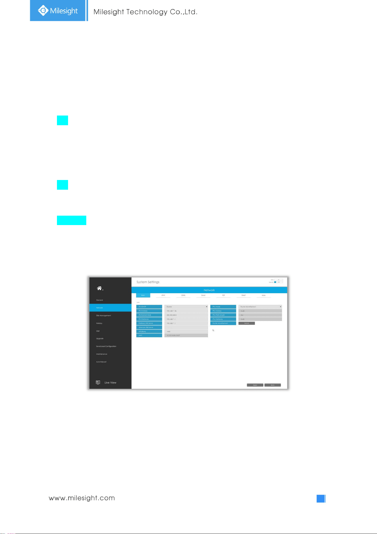
3.7.2.1 Basic
The system supports two IP address format: IPv4 and IPv6
IPv4
Enable IPv4 DHCP to auto search IP. When enable DHCP function, you can not modify IP/ Subnet
mask/ Gateway.
Disable IPv4 DHCP to modify IP/ Subnet mask/ Gateway manually.
IPv6
Manual/ Router Advertisement/ DHCPv6 are available.
DNS Server
Preferred DNS Server: DNS server IP address.
Alternate DNS Server: DNS server alternate address.
Note:
1. Check the DHCP check-box when there is a DHCP server running in the networks.
2. The valid range of MTU is 500~9676.
3. Do not input an IP address conflicting with another device.
4. Working mode option is only for NVR 7000/8000 Series. Internal NIC IPv4 Address is only for
PoE NVR Series.
64
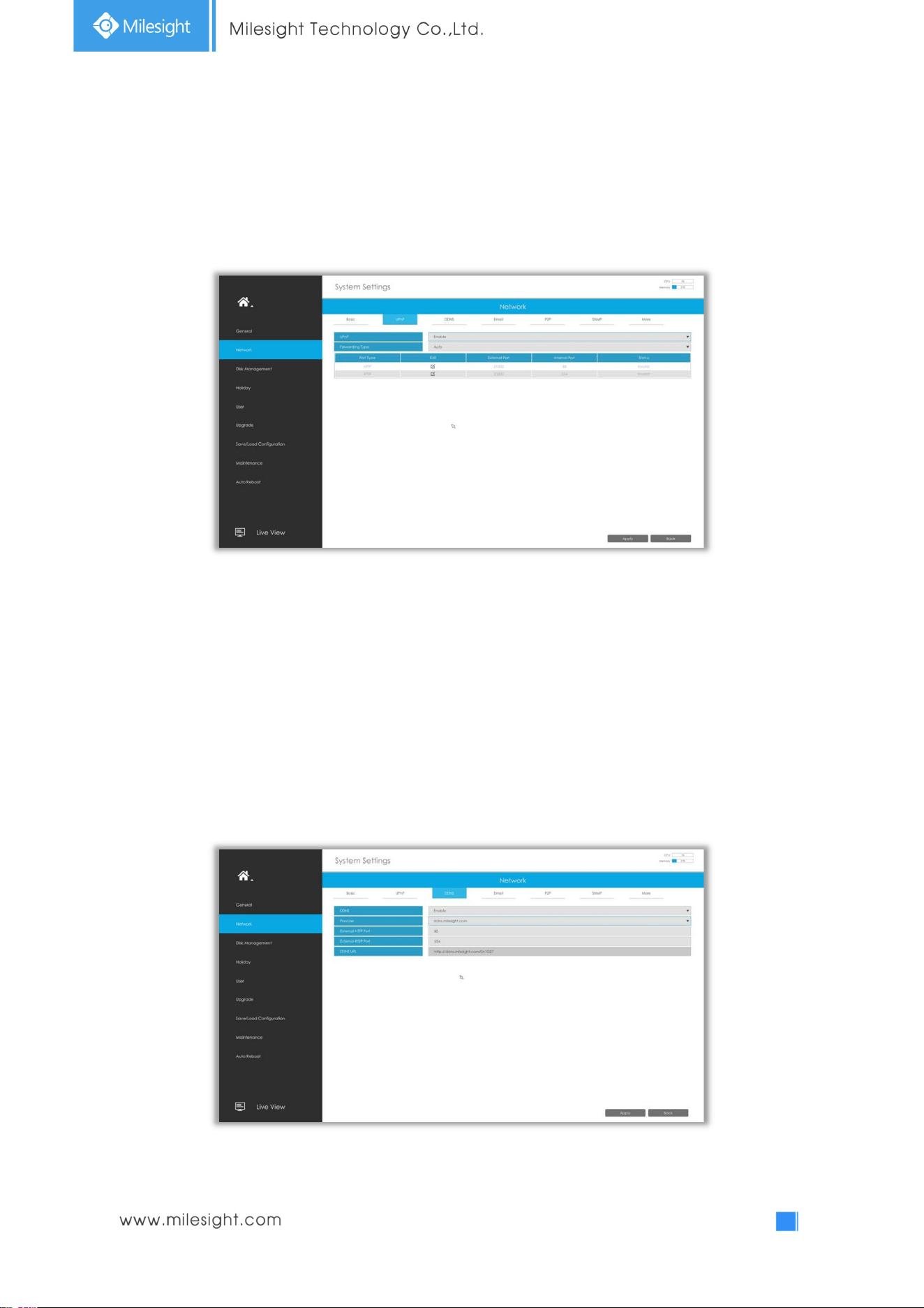
3.7.2.2 UPnP
With the function enabled, you don’t need to configure the port mapping for each port in router, it
will do the port mapping in router automatically once router supports UPnP.
3.7.2.3 DDNS
Using DDNS to solve the dynamic IP address problem.
Check DDNS check-box to enable it, then select a DDNS Server and input the user name, password
and host name. Do not forget to save the configuration.
Milesight has its own DDNS server. Please do port forwarding for HTTP port and RTSP port before
enabling Milesight DDNS. Then input corresponding information and you can use
http://ddns.milesight.com:MAC to access device remotely.
Note: “Host Name” must begin with letters, and it can only contain number, letters, and hyphen.
65
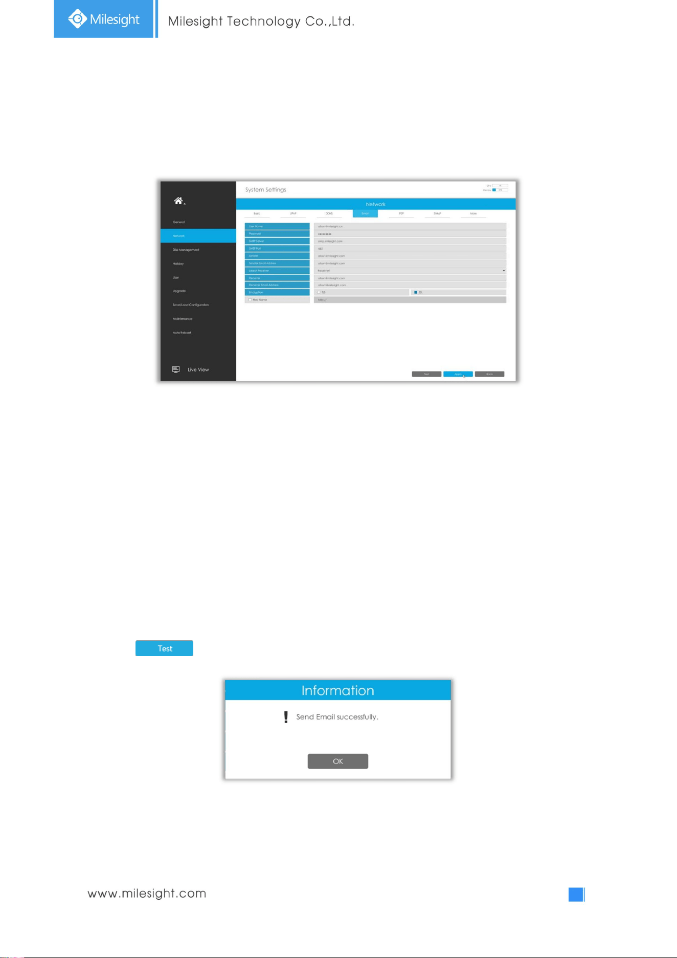
3.7.2.4 Email
Email will send receivers a screenshot when the alarm is triggered.
User name: The E-mail address you choose to send emails. Please input full email address into it.
Password: The password of the E-mail.
SMTP Server: The SMTP Server of your E-mail.
SMTP Port: The port of SMTP Server, it’s usually 25.
Encryption: Security Protocol of email sending, including TLS and SSL.
Host Name: It will be attached in the email.
Sender: Named by yourself for the Sender’s E-mail.
Sender Email Address: It must be same as [User name].
Select Receiver: You can have 3 receivers at most.
Receiver: Named by yourself for the Receiver’s E-mail.
Receiver Email Address: E-mail Address for the receivers.
Select to check if the Mail function is workable.
Note: If your NVR has a port forwarding IP for Host Name, please input the complete address that
contains the port.
66
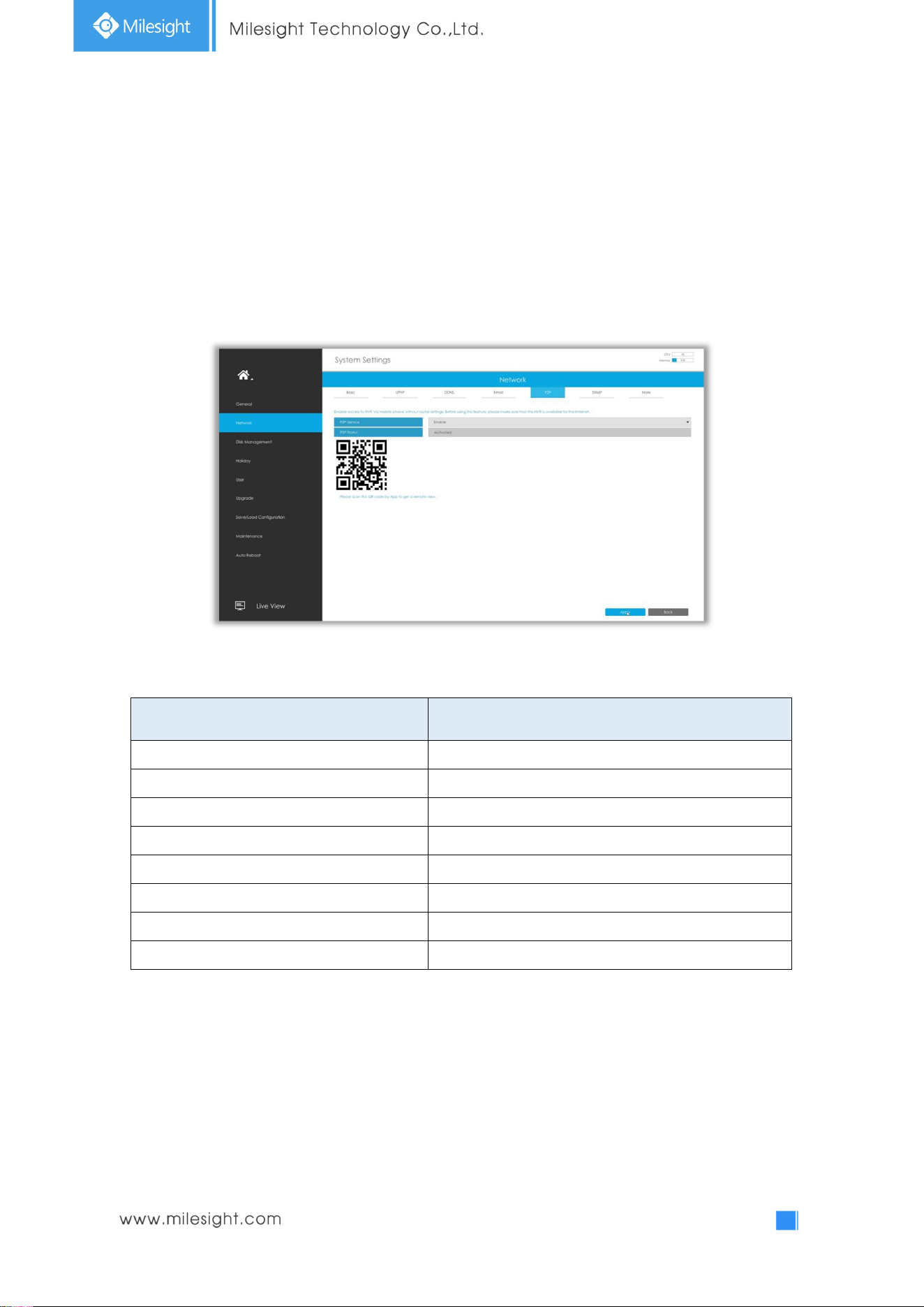
3.7.2.5 P2P
You can watch remote NVR live view in WAN by P2P on M-Sight Pro without doing port forwarding on
router.
Click “Enable” and “Save” to enable P2P.
P2P is enabled successfully when P2P Status shows “Activated”.
After enabling, you can add the NVR on the APP M-Sight Pro for live view via scanning the QR code on
the “P2P” page directly, or inputting the MAC address manually.
There are several status shows on P2P Status after clicking Saving, please check corresponded
possibilities below:
P2P Status Description
Network unavailable Failed to connect with internet
Authentication request failed Failed to authenticate P2P encryption
No idle UUID Please contact Milesight if this status shows up
Activated P2P is available
Login failed Failed to login P2P server
Initialization failed Failed to initialize P2P
Unactivated P2P is disabled
Unknown error Other error
Note:
1. Please make sure that NVR is available for internet before enabling.
2. If your NVR firmware version is not 7x.7.0.9-r2 or above, please contact Milesight to registered
P2P first.
67
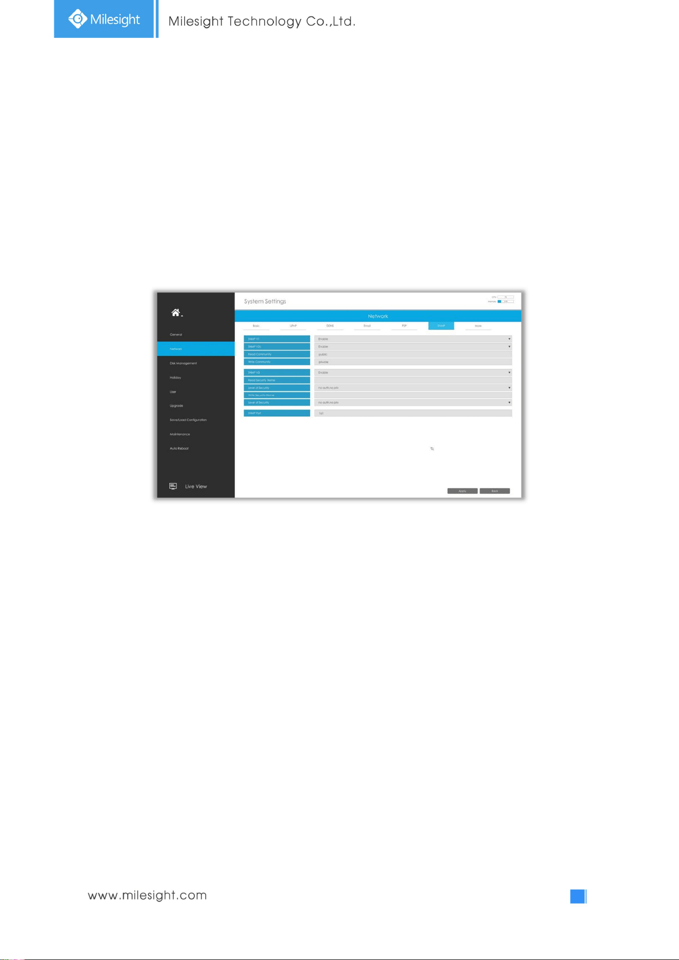
3.7.2.6 SNMP
SNMP is an abbreviation of Simple Network Management Protocol, which is convenient for NVR to be
monitored and managed in the whole network environment. The SNMP is widely used in many
network devices, software and systems.
Before setting the SNMP, please download the SNMP software and manage to receive the NVR
information via SNMP port. By setting the Trap Address, the NVR can send the alarm event and
exception messages to the surveillance center.
SNMP v1/2c/3: The version of SNMP. Please select the version of your SNMP software.
SNMP v1: No security protection
SNMP v2c: Require password for access
SNMP v3: Support encryption on the premise that the HTTPS protocol must be
enabled.
Read Community: Input the name of Read Community
Write Community: Input the name of Write Community
Read Security Name: Input the name of Read Security Community
Level of Security: There are three levels available: (auth, priv), (auth, no priv) and (no auth, no priv)
Write Security Name: Input the name of Write Security Community
Level of Security: There are three levels available: (auth, priv), (auth, no priv) and (no auth, no priv)
SNMP Port: The default of the SNMP port is 161.
68
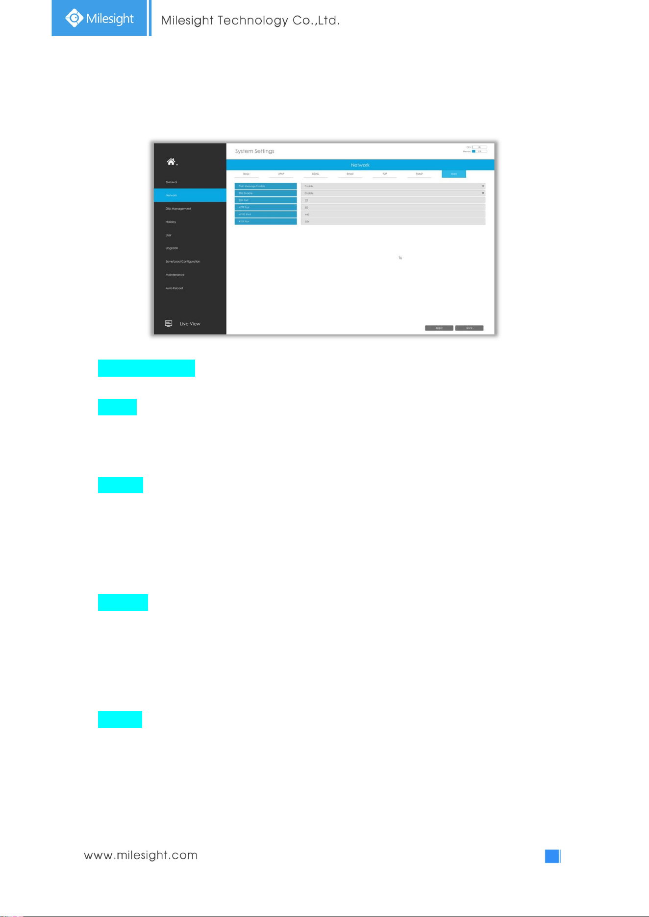
3.7.2.7 More
Push Message Enable
With this option enabled, you can receive the alarm message on the mobile application.
SSH Port
Secure Shell (SSH) has many functions; it can replace Telnet, and also provides a secure channel
for FTP, POP, even for PPP.
Note: The default SSH port is 22. Only for Milesight R&D debugging.
HTTP Port
The default HTTP port is 80. Please modify HTTP ports according to actual application.
Note:
1. The default HTTP port for IE browser is 80.
2. HTTP port is used for remote network access for 4k/H.265 NVR Series.
HTTPS Port
The default HTTPS port is 443. Please modify HTTPS ports according to actual application.
Note:
1. The default HTTPS port for IE browser is 443.
2. HTTPS port is used for remote network access for 4k/H.265 NVR Series.
RTSP Port
Real Time Streaming Protocol (RTSP) is an application layer protocol in TCP/IP protocol system.
The default RTSP port is 554. Please modify RTSP port according to actual application.
Note:
1. RTSP port is used for remote network live view.
2. RTSP port valid range is 554 or 1024~65535.
69
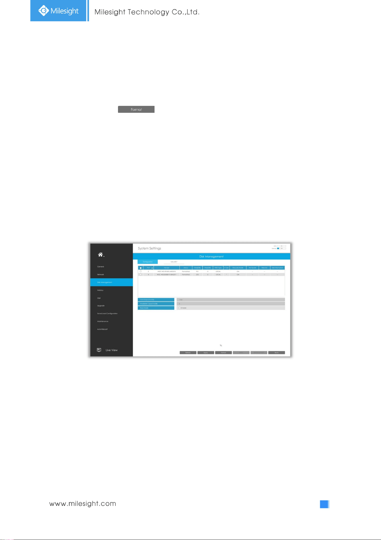
3.7.3 Disk Management
3.7.3.1 Disk Configuration
Select a disk and click to format the disk, set the recycle mode by double clicking the
Mode. After that the disk will be ready.
HDD Type: RAID* means RAID while LOCAL means normal disk mode.
Recycle Mode: Enable recycle mode to enable the recycle for full disk.
Hot Spare: A disk can be used as the hot spare for any array created in the system.
Rebuild: When the array is in Degraded status, the device can start rebuilding the array automatically
with the hot spare disk to ensure the high security and reliability of the data.
Disk information: Click to show the detail information of disk in this array.
70
RAID Mode
RAID (Redundant Array of Independent Disks) is a storage technology that combines multiple disk
drive components into a logical unit. A RAID setup stores data over multiple hard disk drives to
provide enough redundancy so that data can be recovered if one disk fails.
Step1. Select HDD and click .
Step2. Select RAID Type and HDD port, then click to create a new array. New array
will be available after a while.
Note:
1. RAID only available for 4K H.265 NVR 7000/8000 Series.
2. RAID capacity cannot larger than 16TB.
71
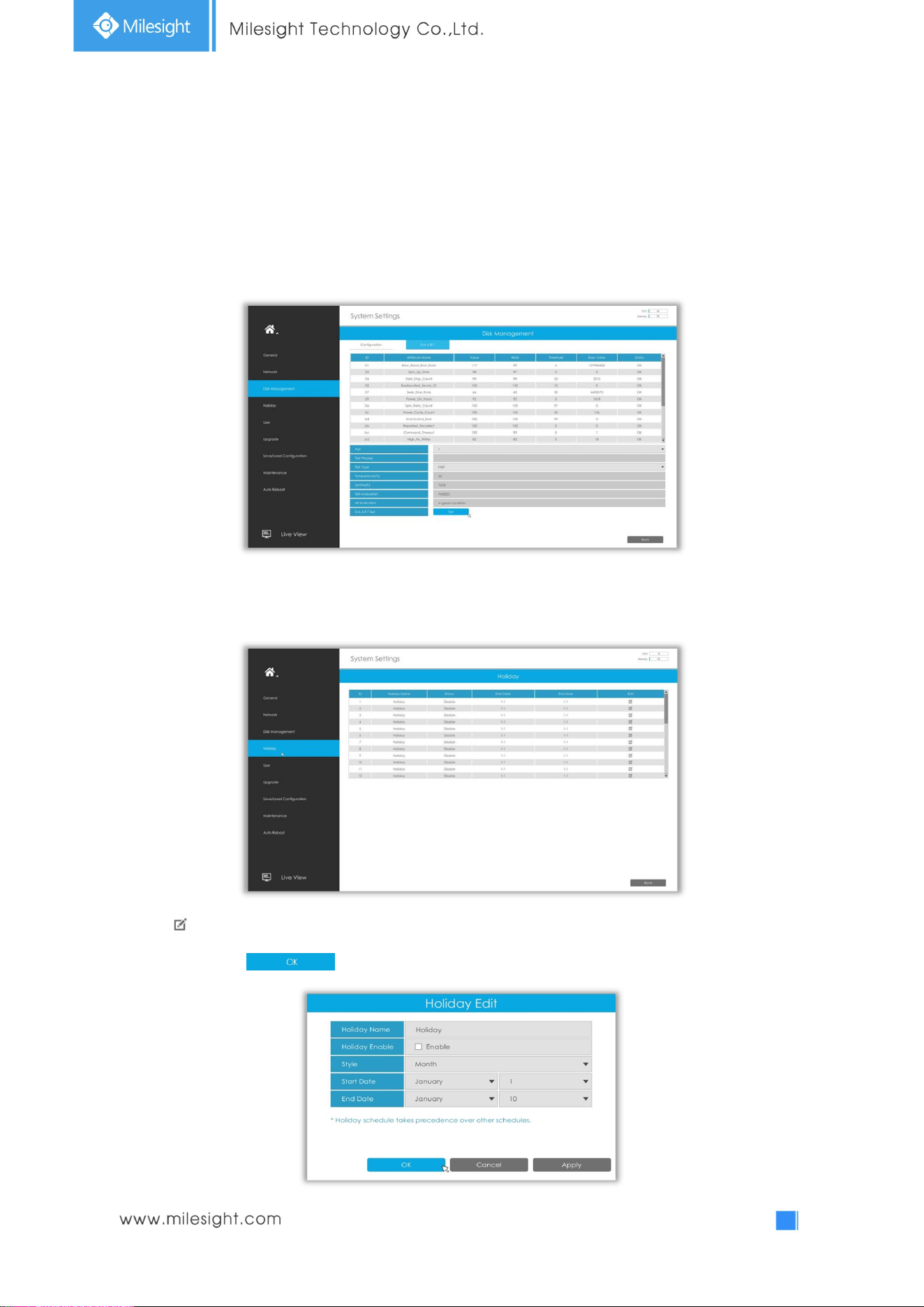
3.7.3.2 S.M.A.R.T Detection
S.M.A.R.T detection is a monitoring system of HDD that detects anticipating failures of HDD and
reports them with various indicators.
Test Type: Fast and Full are available.
Self-evaluation: If the HDD is in good condition, it will pass the self-evaluation.
3.7.4 Holiday
It can configure the record or image capture schedule for holidays of the current year.
Click to edit holiday information, including Holiday Name, Holiday Enable, Style, Start Date and End
Date. Then click to save the configuration.
72
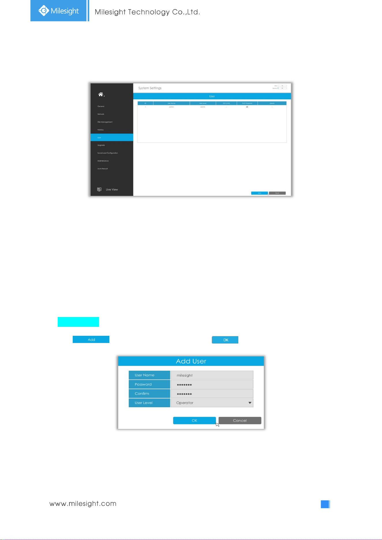
3.7.5 User
Note:
1. If the NVR firmware version out of the factory is xx.7.0.6 or above, the default user name is
“admin” and the default password is “ms1234”;
2. If the NVR firmware is upgraded to xx.7.0.6 or above from a lower version, the default password
will turn to “ms1234” after a reset, or it will keep the old default password “123456”;
3. If the NVR firmware version is below xx.7.0.6, the default user name is “admin” and the default
password is “123456”.
Add a new user
Click , then input user information and click to add a new user.
Note: The user name can only contain letters and number. There are two user levels with different
authority: Operator and Viewer.
73
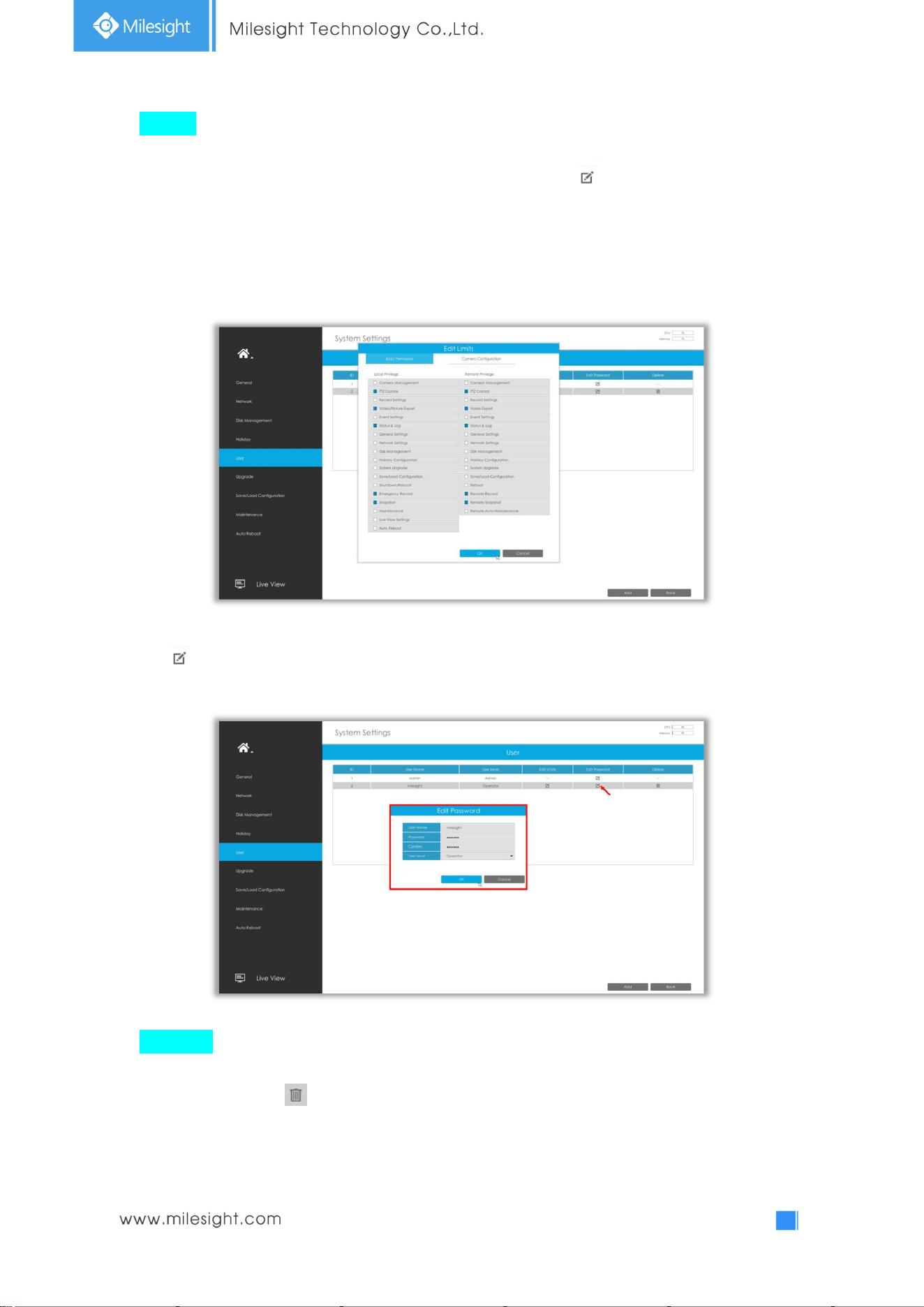
Edit user
Select a user, when the background color changes into dark gray, click to edit user privileges.
① Local Privilege means that the privilege to the monitor connected with NVR.
② Remote Privilege means that the privilege to web settings.
Click to modify password.
Delete user
Select a user and click to delete a user.
74
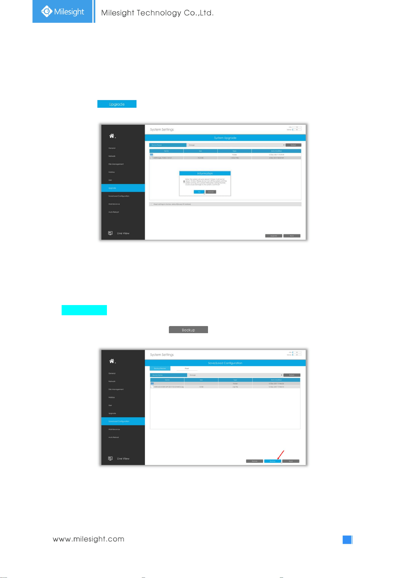
3.7.6 Upgrade
Step1. Search for USB device, and select the corresponding firmware.
Step2. Click confirm the upgrade.
Note: The system will auto reboot after confirming upgrade.
3.7.7 Save/Load Configuration
Backup/Restore
Backup: Select a folder and then click to export configuration to USB device.
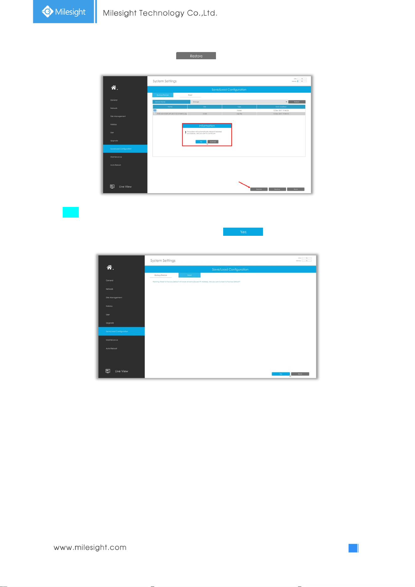
75
Restore: Select a .cfg file and then click to import configuration to your NVR.
Reset
All parameters can be reset to default settings by clicking .
76
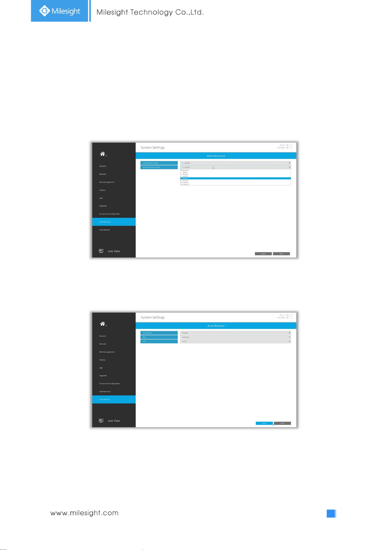
3.7.8 Maintenance
The NVR will automatically delete your logs and photos after the retention period or permanently
keep the Log and Photo according to your configuration.
Permanent, 1 Month, 2 Months, 4 Months, 6 Months, 8 Months, 10 Months and 12 Months are
available for these two options.
3.7.9 Auto Reboot
You can set day and time for reboot, and the NVR will reboot automatically at the time you set.
Day: Everyday, Monday, Tuesday, Wednesday, Thursday, Friday, Saturday and Sunday.
Time: 00:00, 01:00, 02.00 ....... 22:00, 23:00.
77
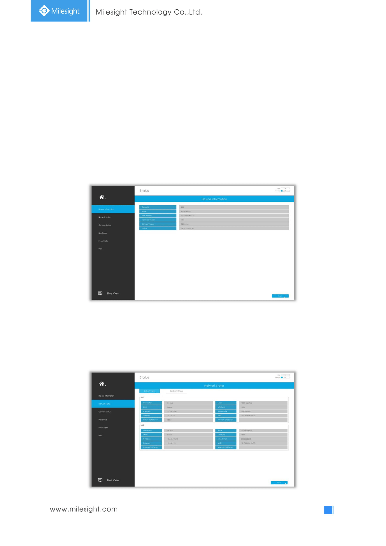
3.8 Status
You can have a quick view of the information of the device, network, camera, disk and event. This part
is only for your rapid reference. If you want to make any configuration, please go to corresponding
parts accordingly.
3.8.1 Device Information
Device Information includes Device ID, Model, MAC Address, Hardware Version, Software Version, and
Uptime.
3.8.2 Network Status
Network Status includes three main parts: Bandwidth Status, LAN1 and LAN2.
78
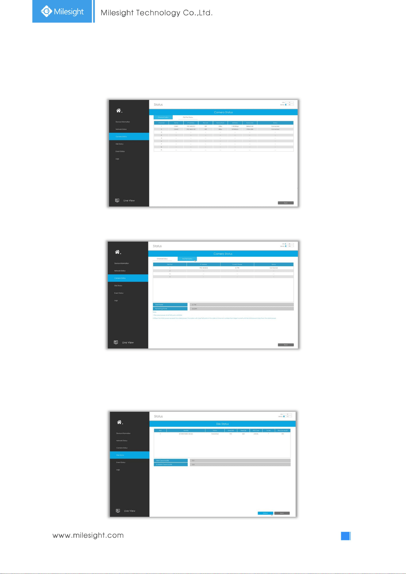
3.8.3 Camera Status
Camera Status includes Channel, Name, IP Address, Record, Frame Rate, Bit Rate, Frame Size and
Status.
The PoE Port Status is only for PoE NVR, it will show you the current power and connection status of
PoE ports.
3.8.4DiskStatus
Disk Status includes Port, Vendor, Status, Total(GB), Free(GB), HDD Type, In Use and Recycle Mode.
The user can see the Total Capacity (GB) and Available Capacity (GB) as well.
79
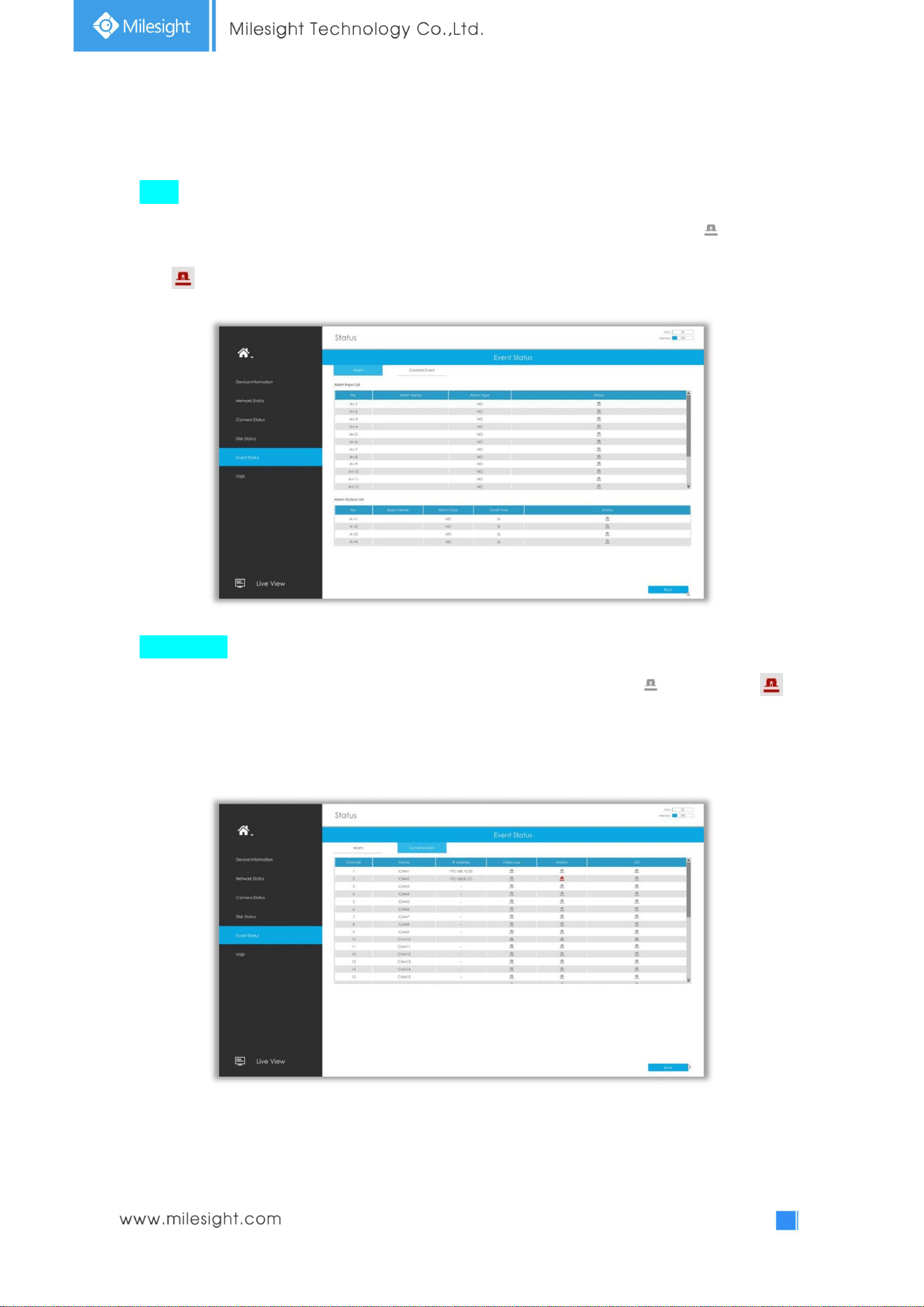
3.8.5 Event Status
Alarm
The user can check Alarm Input and Output list here if NVR has corresponded interface. will turn
into when the corresponding alarm is triggered.
Camera Event
The user can check Camera Event here, including Video Loss, Motion and I/O. will turn into
when the corresponding alarm is triggered.
80
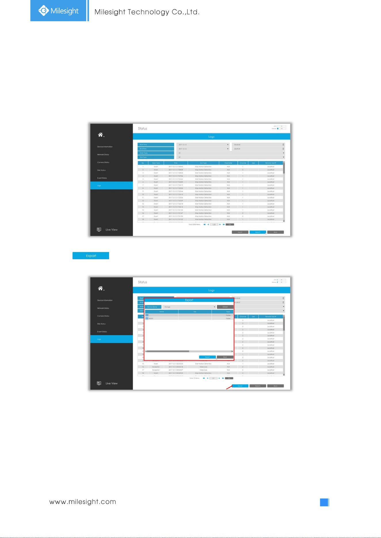
3.8.6 Logs
The user can check, search and export logs in Logs interface. By selecting the Start Time, End Time,
Main Type and Sub Type, which can narrow down the scale of logs, you can search for logs that you
need.
Click to export searched logs to media device.
81
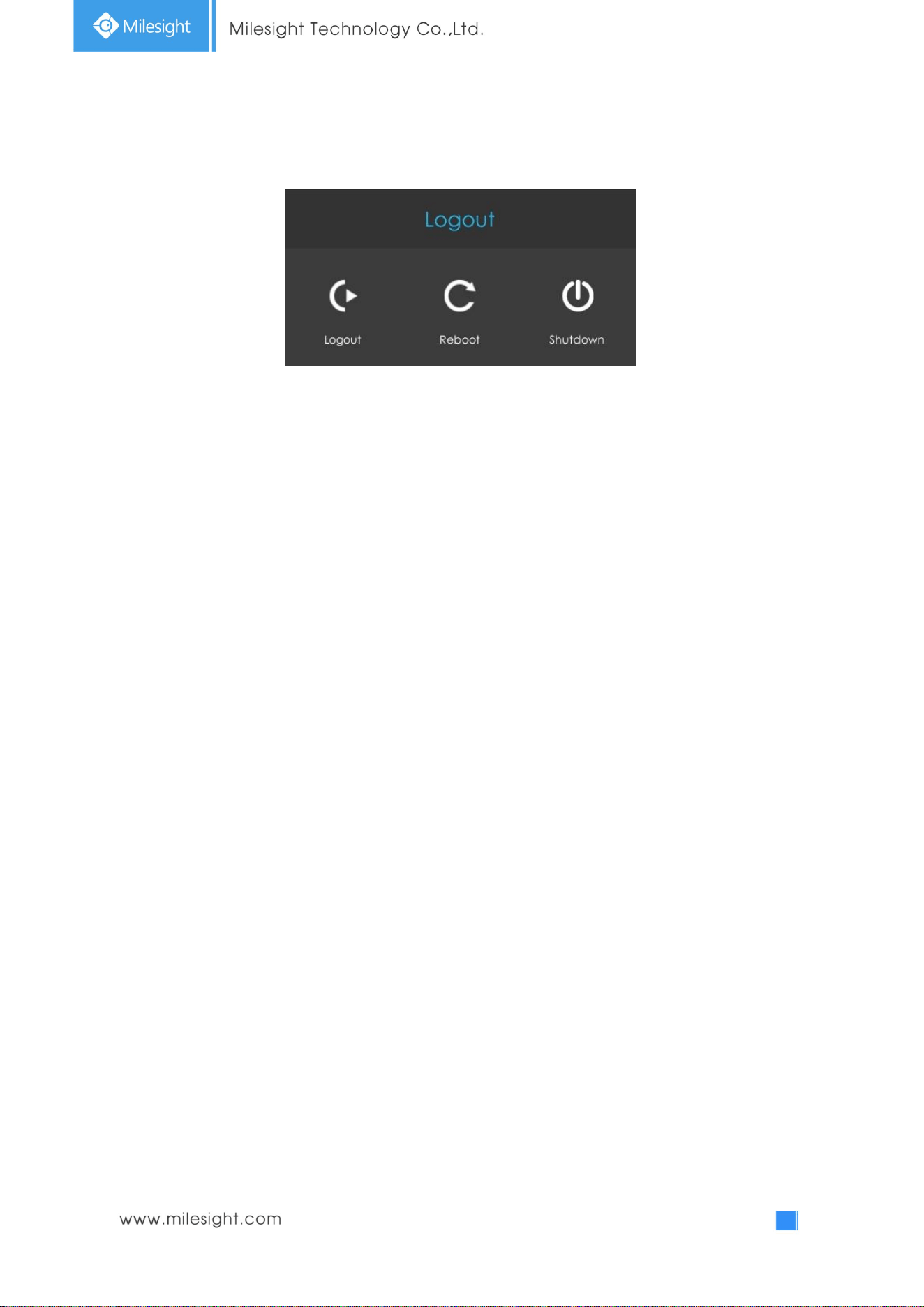
3.9 Logout
Logout: Exit the current login account.
Reboot: Restart the NVR.
Shutdown: Close the NVR.
82
4.WEBSettings
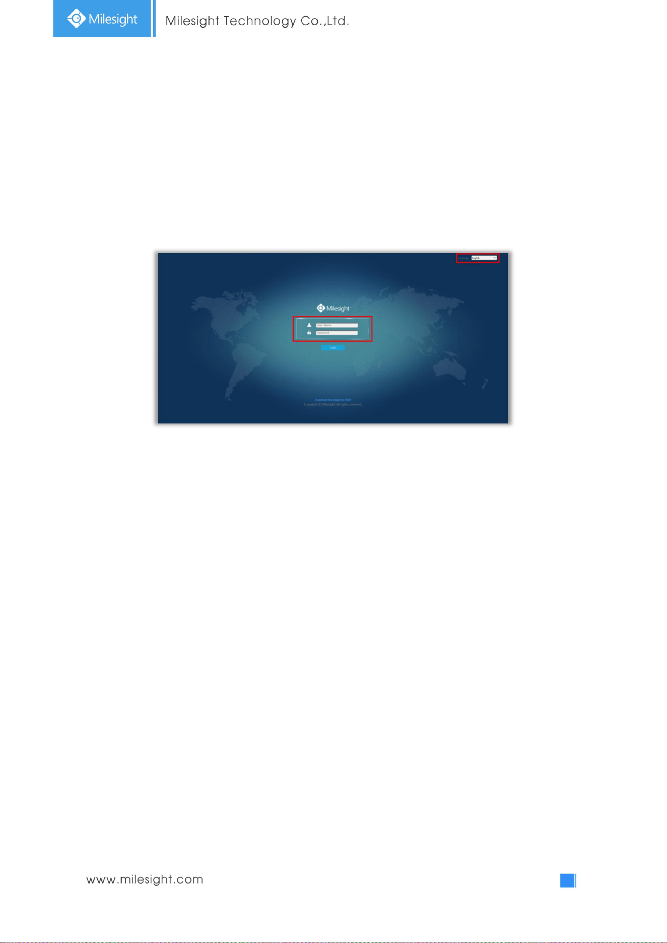
4.1 Login
Select Language on the top-right of interface.
Input the user name, password and click Login to login NVR web page.
Note:
1. If the NVR firmware version out of the factory is xx.7.0.6 or above, the default user name is
“admin” and the default password is “ms1234”.
2. If the NVR firmware version is below xx.7.0.6, the default user name is “admin” and the default
password is “123456”.
3. If the NVR firmware is upgraded to xx.7.0.6 or above from a lower version, the default password
will turn to “ms1234” after a reset, or it will keep the old default password “123456”.
83
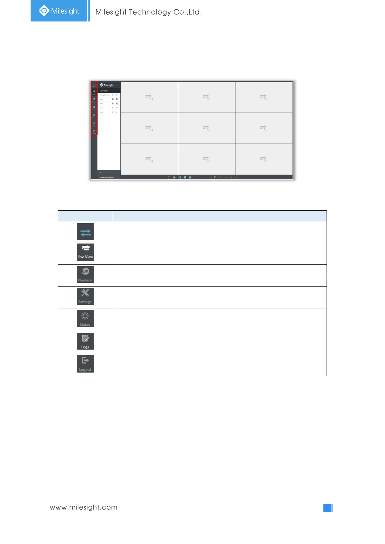
4.2 Menu
Icons Descriptions
Hide or show secondary menu
Live view
Play back the video
Make settings for Camera, Record, Event and System
Check Device
Information, Network Status, Camera Status, Disk Status and
Event Status
Check all operation logs
Log out NVR
84
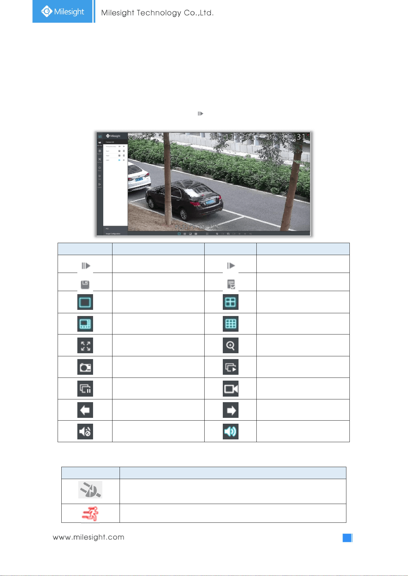
4.3Live View
4.3.1 Camera List
List and play added cameras on Camera List page.
Select one window one camera to play. Or click to get all cameras’ live video.
Icons Descriptions Icons Descriptions
Play Primary Stream Play Secondary Stream
Save View Play default view
1 screen mode 4 screens mode
8 screens mode 9 screens mode
Full screen Digital zoom
Snapshot Start all live view
Stop all live view Record
Previous page Next page
Audio on Audio off
And there are multiple icons on each channel displayed in live view, indicating video loss and alarm
status of the channel.
Icons Descriptions
It indicates video loss
It indicates motion detection alarm
85
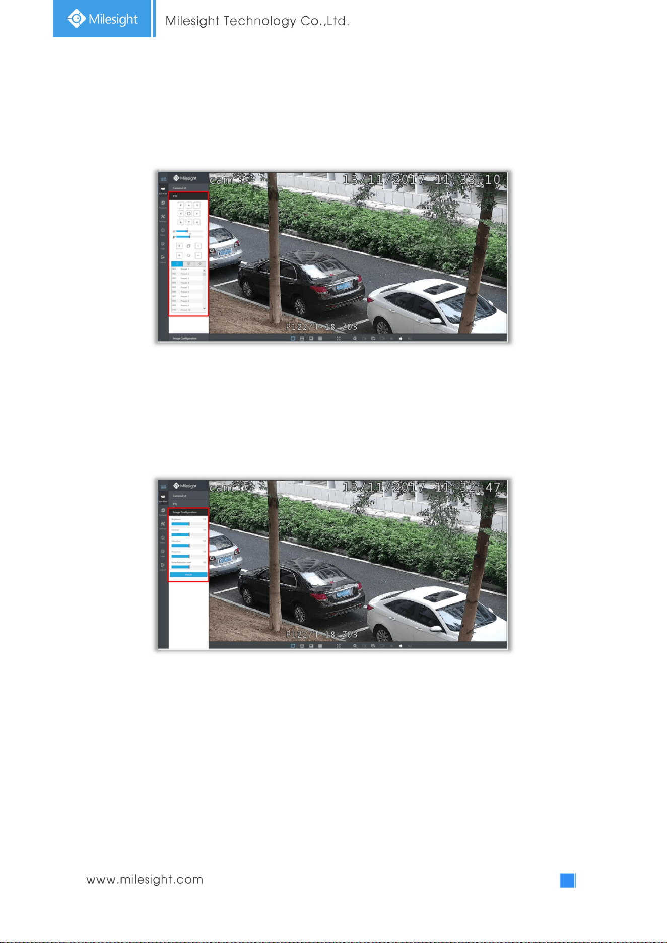
4.3.2 PTZ
Operating PTZ, Preset, Patrol and Pattern on PTZ page.
4.3.3 Image Configuration
Adjust image Brightness, Contrast, Saturation, Sharpness and Noise Reduction Level on Image
Configuration page.
86
4.4 Playback
To play and backup the recorded files.
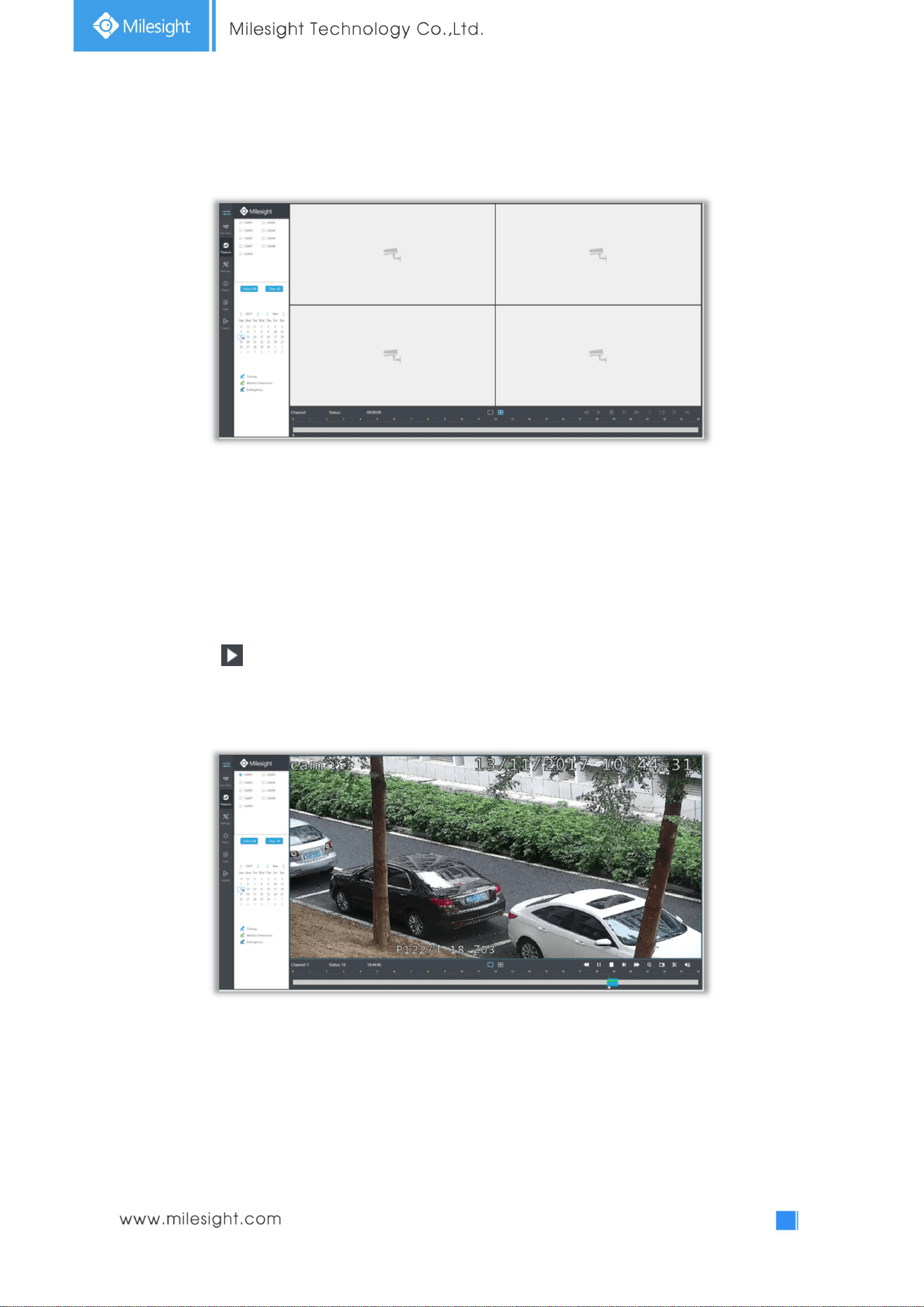
4.4.1 How to playback
It supports playback according to recorded time. Play recorded files in specified time period.
Step1. Select channel and date.
Step2. Select record types: Timing, Motion Detection or Emergency.
Step3. Click to play.
Note: Only the day with a red mark means that there are recorded files.
87
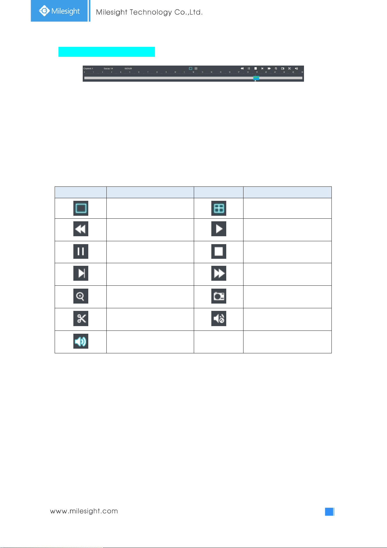
Video Playback Tool Bar Description
The tool bar can display multi-event record. It shows that in this record period what kind of event has
happened. The symbolic meaning of each color is shown below:
Blue—Timing Green --- Motion
Red --- Alarm Purple --- Emergency
And take this bar above as an example, it means in this recording period, timing and motion event
have been triggered.
Icons Descriptions Icons Descriptions
1 screen mode 4 screens mode
Speed Down Play
Pause Stop
Forward Step Speed Up
Digital Zoom Snapshot
Backup Audio On
Audio Off
88
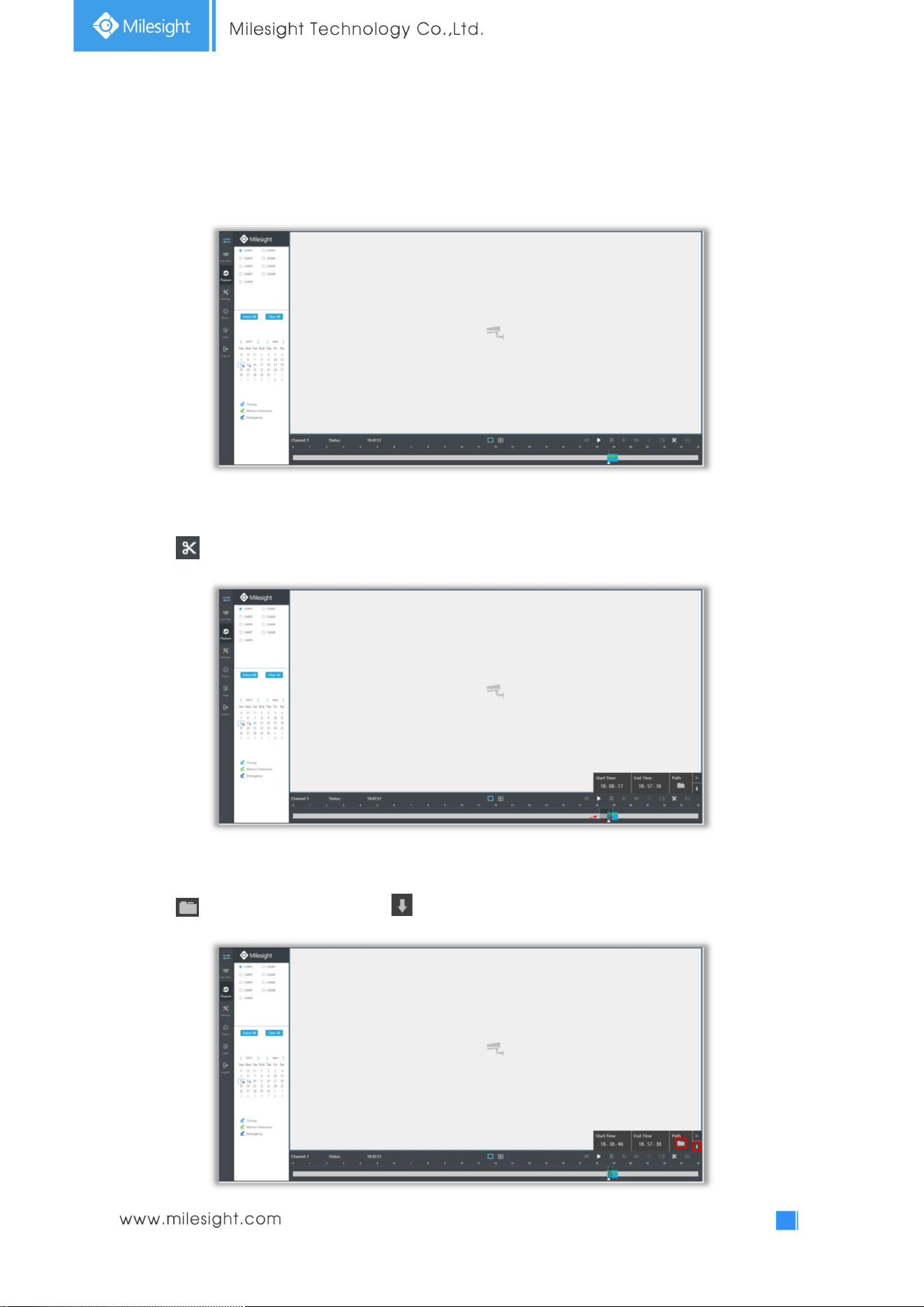
4.4.2 Video Files Backup
Recorded files can be cut and backed up from WEB.
Step1. In playback interface, select camera, the date and time to playback.
Step2. Select Recorded files for Backup.
Click , then select start time and end time by dragging the vertical line on the time bar.
Step3. Backup the recorded files.
Click to select file path, then click to back up recorded files.
89
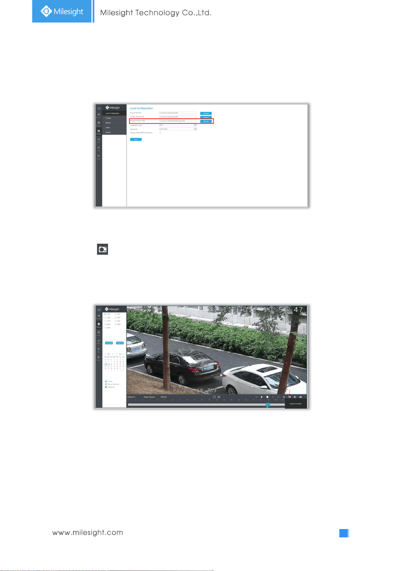
4.4.3 Picture Files Backup
Step1. Browse a file path in Local Configuration interface.
Step2. Pause first when you want to backup a special scene during video playback.
Step3. Click to save the picture.Then the backup picture can be found in the files path you set
before.
Note: It is recommended to run browser as administrator before getting playback snapshot.
]
90
4.5 Settings
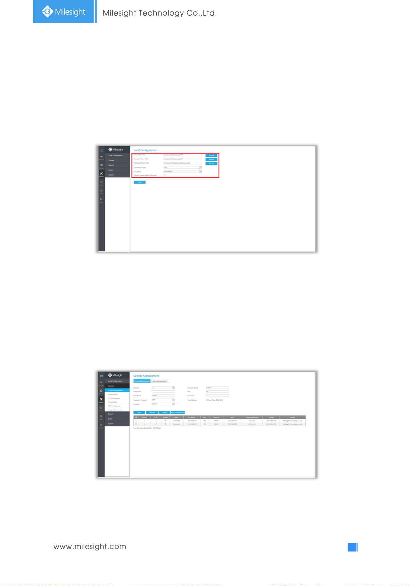
4.5.1 Local Configuration
Local Configuration includes Record File Path, Preview Picture Path, Playback Preview Path,
Connection Type, Play Mode and Primary Stream When Fullscreen option.
4.5.2 Camera
Before configuration, please ensure that camera is connected to the same network as your NVR and
the network setting for your NVR is properly setup.
4.5.2.1 Camera Management
91
Step1. Add Camera.
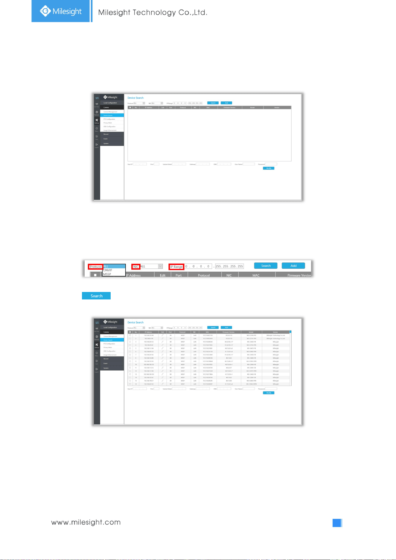
Method1. Add IP Channel in Device Search interface. ‘Settings’à ‘Camera’à ‘Device Search’.
1. Select IP Range, NIC and Protocol, which includes ALL, ONVIF and MSSP.
MSSP: You can search out all Milesight camera which has different network segment in the LAN.
2. Click to search cameras at the same network segment with NVR.
92
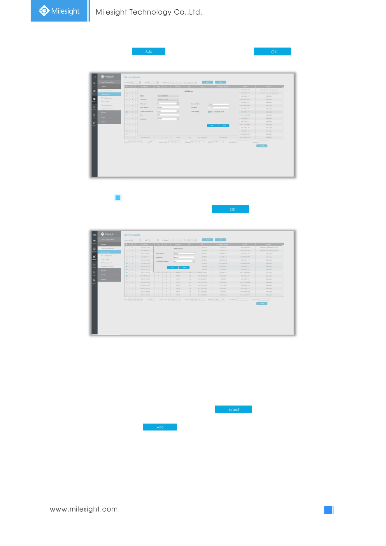
3. Select one channel, click button, input password and click to finish.
4. Or you can check to batch adding the network cameras if they are of the same password, and
you can choose TCP or UDP transport protocol for it. Click to finish batch adding.
Note:
The steps for adding the third party PoE cameras plugged into Milesight PoE NVR:
① Set camera’s IP segment to the same as NVR PoE NIC before plugging into PoE NVR;
② Select PoE for NIC in Device Search interface, click to search out cameras;
③ Select cameras and click to add them.
93
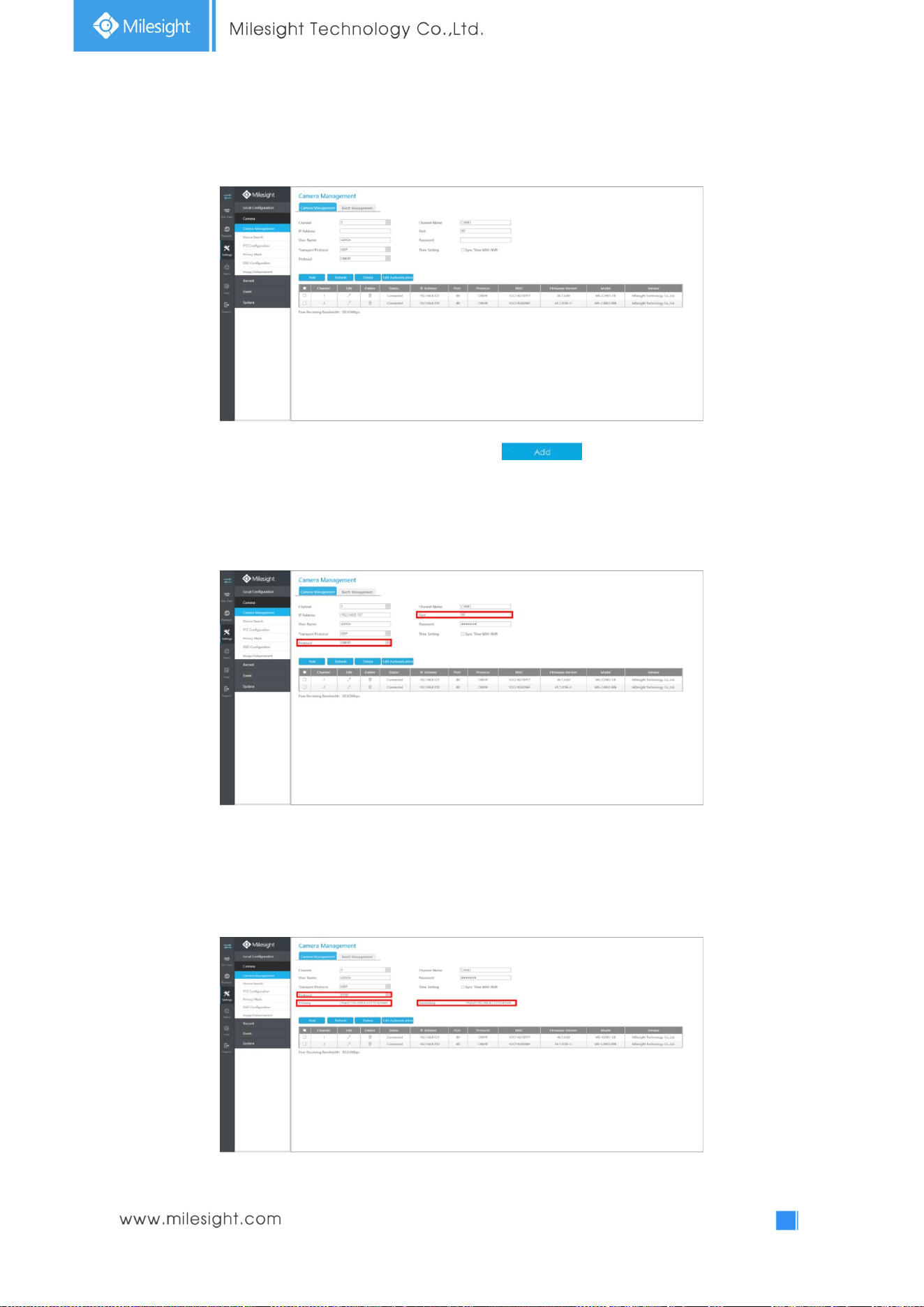
Method2. Add camera through camera management interface. ‘Settings’ à ‘Camera’ à ‘Camera
Management’.
Select channel id, input complete information, then click button.
There are three protocols available for camera connection:
l ONVIF: You can add any IP cameras with ONVIF protocols.
l RTSP: You can add any IP cameras with RTSP protocol streams (Port: 554). It needs you
to input complete resource path of the IP camera to add it. Take Milesight device for example,
the resource path of main stream is “rtsp://IP:port/main” and second stream is
“rtsp://IP:port/sub”.
94
l MSSP: You can add Milesight cameras which are in the same LAN with this protocol.
Step2. Check the connection status.
After adding the IP channels, click on Camera Management interface, then
appears under Status. If it doesn’t appear, you need to check if the network is connected or whether
the user name, password is correct or not.
Step3. Configure IP Channel.
Configure one camera
After successfully adding the channel, click to re-edit the channel info.
Select [Parameters] page to re-edit this channel parameters. Click to save the
configuration.
95
You can delete this channel by clicking , or you can select multiple devices and then click
to delete.
Batch configuring camera
Click , select multiple channels and set cameras parameters.
Note: The user name and password entered here are the default user name and password. The
management port is 80 and the default Transport protocol is UDP.
96
Step5. Configure PoE Channel(Only for PoE NVR)
1. Connect camera to PoE port, it will detect the camera automatically.
2. If the camera's password is "ms1234", it will be successfully authenticated and be changed into the
same network segment with internal NIC IPv4 address, then the camera will be connected
successfully.
3. If the camera's password is not "ms1234", the PoE channel will show disconnect status. You need to
input the camera's password by clicking to realize authentication ( you can also
multi-select the devices and then click this button). Then the camera will be changed into the same
network segment with internal NIC IPv4 address and will be successfully connected. In next time, NVR
will use the password you input to authenticate this camera when you re-plug it.
97
4.5.2.2 Device Search
Select Protocol and NIC, set the IP range, then click to quickly search the IP devices that
support selected protocol at the same LAN with NVR.
Select channels andbatch editing their IP information.
98
4.5.2.3 PTZ Configuration
Select a channel and set the PTZ parameters. You can select [Copy to Camera] to copy the same
configuration to other channels.
Note:
1. The PTZ protocol and address of IP channel must be consistent with those of the PTZ
decoder.
2. Settings for a PTZ camera must be configured before it can be used. Make sure that the PTZ
and RS-485 of the NVR are connected properly.
99
4.5.2.4 Privacy Mask
Milesight NVR support to set privacy masks. It is used to cover some privacy area which is not proper
to appear on monitor.
You can add a privacy mask by following steps:
Step1. Select channel and enable privacy mask.
Step2. Set the privacy mask type and drag the mouse to select the area which is privacy on the live
window. You can add 4 areas at most.
Step3. You can click [Copy to Camera] to copy the same configuration to other channels.
Step4. Select “Save” to save the settings.
100
4.5.2.5 OSD Configuration
You can set OSD (On Screen Display) on NVR, and the OSD will be synchronized to Camera.
Select channel and finish the info and save.
[Video Stream]: Select stream. All Streams, Primary Stream and Secondary Stream are available.
[Show Video Title]: Enable it and the video title will be shown on screen.
[Video Title]: Set the video title for the channel.
[Title Position]: Set the position for the video title: Top-Left, Top-Right, Bottom-Left or Bottom-Right.
[Show Timestamp]: Enable or disable timestamp.
[Date Format]: Set format for date: YYYY-MM-DD, MM/DD/YY or DD/MM/YYYY.
[Date Position]: Set the position for the date: Top-Left, Top-Right, Bottom-Left or Bottom-Right.
You can also click [Copy to Camera] to copy the same configuration to other channels.
101
4.5.2.6 Image Enhancement
You can set Image Enhancement on NVR, and the configuration will be synchronized to Camera.
Step1. Select channel.
Step2. Set the configuration.
Day/Night Mode: Set the Day/Night mode for the channel.
Day to Night Value: Set the Minimum illumination intensity to trigger Night Mode.
Night to Day Value: Set the Maximum illumination intensity to trigger Day Mode.
IR Light Sensor Value: Shows the current value of IR light sensor.
Power Line Frequency: 50Hz and 60Hz are available.
Corridor Mode: Set corridor mode.
Image Rotation: Set image rotation.
IR Balance Mode:Turn on to avoid IR overexposure.
White Balance: Choose a white balance mode for the channel.
Digital Anti-fog Mode: Set the Anti-fog function on and off.
WDR/HLC: Click to configure Wide Dynamic Range or High Light Control.
Step4. You can click [Copy to Camera] to copy the same configuration to other channels.
102
4.5.3 Record
Preparation for Configuration
Step1. Ensure your NVR has installed and initialized the HDD.
Step2. Ensure that the HDD has sufficient storage space.
Select [Recycle Mode] to "ON" in the case of insufficient capacity of HDD on Disk Management
interface .
103
4.5.3.1 Record Schedule
Record Schedule
Step1. Select Record Schedule.
Step2. Select the desired channel.
Step3. Set record schedule.
Select record type includes Timing, Motion Detection, Alarm and Motion&Alarm, then set the time
you want to record. It is convenient for you to set all or clear all schedule by clicking or
.
Also, you can click the time bar and reedit the record time
104
Click [Copy to Camera] to copy the same configuration to other channels.
Batch Settings
Record and Stop are available for user to set or clear always record schedule for selected channels.
105
4.5.3.2 Advanced
Make advanced configuration for selected channels. Click [Copy to Camera] and to copy the same
configuration to other channels.
Channel: Select the channel which will be set.
Pre Record : Enable/Disable pre-record. It will start recording before the event is triggered.
Duration Time: Event pre-record duration time.
Post Record:Enable/Disable post record. It will keep recording after the event is over.
Duration Time: Event post-record duration time.
Audio Record: Select to record audio or not.
Record Stream Type: Select Main stream or sub stream for record.
Due Time: Set the due time of recording files.
Click [Copy to Camera] to copy the same configuration to other channels.
.
106
4.5.4 Event
4.5.4.1 Motion Detection
Step 1. Enable Motion Detection.
Select channel , Sensitivity and click to enable Motion Detection.
Step2: Set the area for triggering motion detection.
You can select an area by dragging the mouse to set the trigger area, and this area will be
synchronized to camera.
107
Step 3. Set Action for motion detection alarm by clicking .
Record: Record when an alarm is triggered.
Select the operation type: Motion or Motion&Alarm. Then drag a line on the time table for time
setting, it will be more convenient by clicking or to set or clear all time
settings.
What’s more, you can click time bar to edit the time accurately.
Click to copy time setting to other day.
Audible Warning: NVR will trigger an audible beep when motion is detected.
Drag a line on the time table for time setting, it will be more convenient by clicking or
to set or clear all time settings.
What’s more, you can click time bar to edit the time accurately.
Click to copy time setting to other day.
Trigger Interval: The effective interval between two actions when event triggered.
108
Email Linkage: NVR will send an email to the address you set before.
Drag a line on the time table for time setting, it will be more convenient by clicking or
to set or clear all time settings.
What’s more, you can click time bar to edit the time accurately.
Click to copy time setting to other day.
Trigger Interval: The effective interval between two actions when event triggered.
Alarm Output: Trigger alarm output when alarm is triggered.
Other Channels: Trigger other channels record when alarm is triggered.
109
Step 5. Click [Copy to Camera] and to copy the same configuration to other channels.
4.5.4.2 Video Loss
Step1. Select a channel
Step2. Set Action for video loss.
Audible Warning: NVR will trigger an audible beep when alarm is triggered.
Drag a line on the time table for time setting, it will be more convenient by clicking or
to set or clear all time settings.
What’s more, you can click time bar to edit the time accurately.
Click to copy time setting to other day.
Trigger Interval: The effective interval between two actions when event triggered.
110
Email Linkage: NVR will send an email to the address you set before.
Drag a line on the time table for time setting, it will be more convenient by clicking or
to set or clear all time settings.
What’s more, you can click time bar to edit the time accurately.
Click to copy time setting to other day.
Trigger Interval: The effective interval between two actions when event triggered.
Alarm Output: Trigger alarm output when alarm is triggered.
Step 3. Click [Copy to Camera] and to copy the same configuration to other channels.
111
4.5.4.3 Alarm Input
Alarm Input function is supported by UI-5016-B, UI-7016-B, UI-7032-B, UI-8032-B, UI-5016-PB, and
UI-7032-PB.
Step1. Set Alarm input Number, Alarm Name and Alarm Type.
Alarm Input No.: The channel which has input signal.
Alarm Name: Set a name for the alarm.
Alarm Type: Choose NO or NC alarm type for the alarm.
Step2. Set action for alarm input.
Record: Start recording when alarm is triggered.
Trigger Channel Record:Trigger selected to record when alarm is triggered.
Channel Record Schedule: Set record schedule for selected channel. Also you can click
to copy the schedule to other channel.
Select the operation type, including Alarm and Motion&Alarm. Then drag a line on the time table for
time setting, it will be more convenient by clicking or to set or clear all
time settings.
What’s more, you can click time bar to edit the time accurately.
Click to copy time setting to other day.
Copy to Alarm: Copy alarm settings to other channels which has alarm input.
112
Audible Warning: NVR will trigger an audible beep when alarm is triggered.
Trigger Interval: The effective interval between two actions when event triggered.
Click [Copy to Alarm] and to copy the same configuration to other channels.
Email Linkage: NVR will send an email to the address you set before.
Trigger Interval: The effective interval between two actions when event triggered.
Click [Copy to Alarm] and to copy the same configuration to other channels.
Alarm Output: Trigger alarm output when alarm is triggered.
1
13
4.5.4.4 Alarm Output
Alarm Input function is supported by UI-5016-B, UI-7016-B, UI-7032-B, UI-8032-B, UI-5016-PB, and
UI-7032-PB.
Step 1. Set Alarm output channel, Alarm Type, Delay and Alarm Name.
Alarm Output No.: The channel which will output the alarm signal.
Alarm Type: Select alarm type: NO or NC.
Delay: Set the output time for alarm. If the output alarm lasts too long, you can select the Manually
Clear to stop it.
Alarm Name: Set a name for the alarm.
Step 2: Set effective time.
Step3. Click [Copy to Alarm] and to copy the same configuration to other alarm channels.
114
4.5.4.5 Exception
Step1. Select Exception Type.
Network Disconnected: Loss of network.
HDD Full: HDD full, it usually happens when Recycle Mode is OFF.
Record Failed: Recording fails, including HDD Failed, HDD Full and so on.
HDD Failed: Failed to recognize HDD.
HDD Unformat: HDD is unformat.
No Disk: There is no HDD.
Step2. Select normal linkage includes Pop up Alarm, Audible Warning and Email Linkage.
Pop Up Alarm:A window will be popped up in Live View if an alarm is triggered.
Audible Warning: NVR will trigger an audible beep.
Email Linkage: An alarm Email will be sent if an alarm is triggered.
115
4.5.5 System
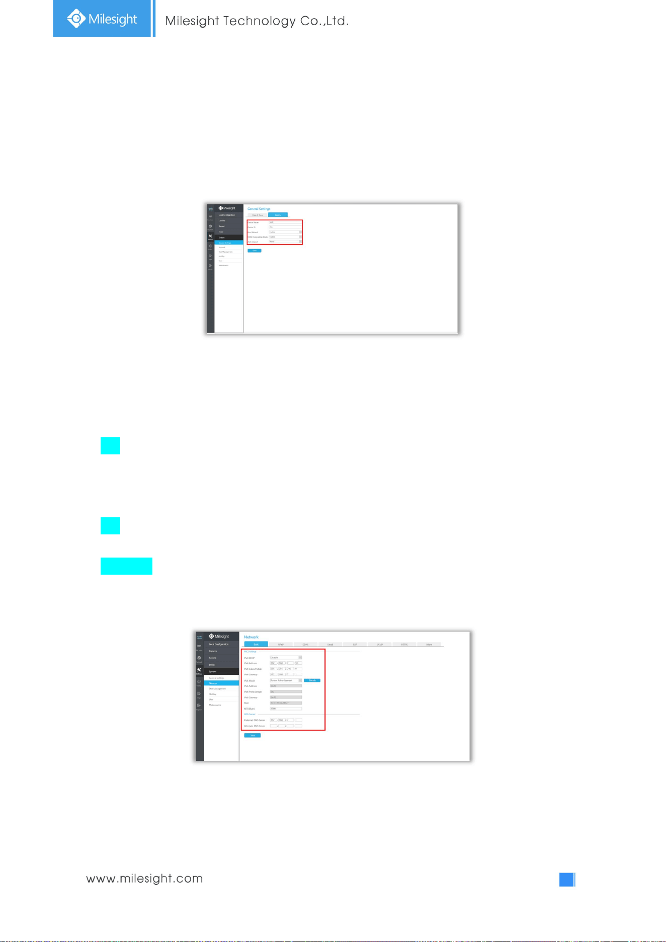
4.5.5.1 General Settings
To setup the general parameters of NVR, including modify the Device Name, Device ID, set system
time manually and auto logout, etc.
4.5.5.2 Network
4.5.5.2.1 Basic
The system supports two IP address format: IPv4 and IPv6
IPv4
Enable IPv4 DHCP to auto search IP. When enable DHCP function, you can not modify IP/ Subnet
mask/ Gateway.
Disable IPv4 DHCP to modify IP/ Subnet mask/ Gateway manually.
IPv6
Manual/ Router Advertisement/ DHCPv6 are available.
DNS Server
Preferred DNS Server: DNS server IP address.
Alternate DNS Server: DNS server alternate address.
Note:
1. Check the DHCP check-box when there is a DHCP server running in the networks.
2. The valid range of MTU is 500~9676.
3. Do not input an IP address conflicting with another device.
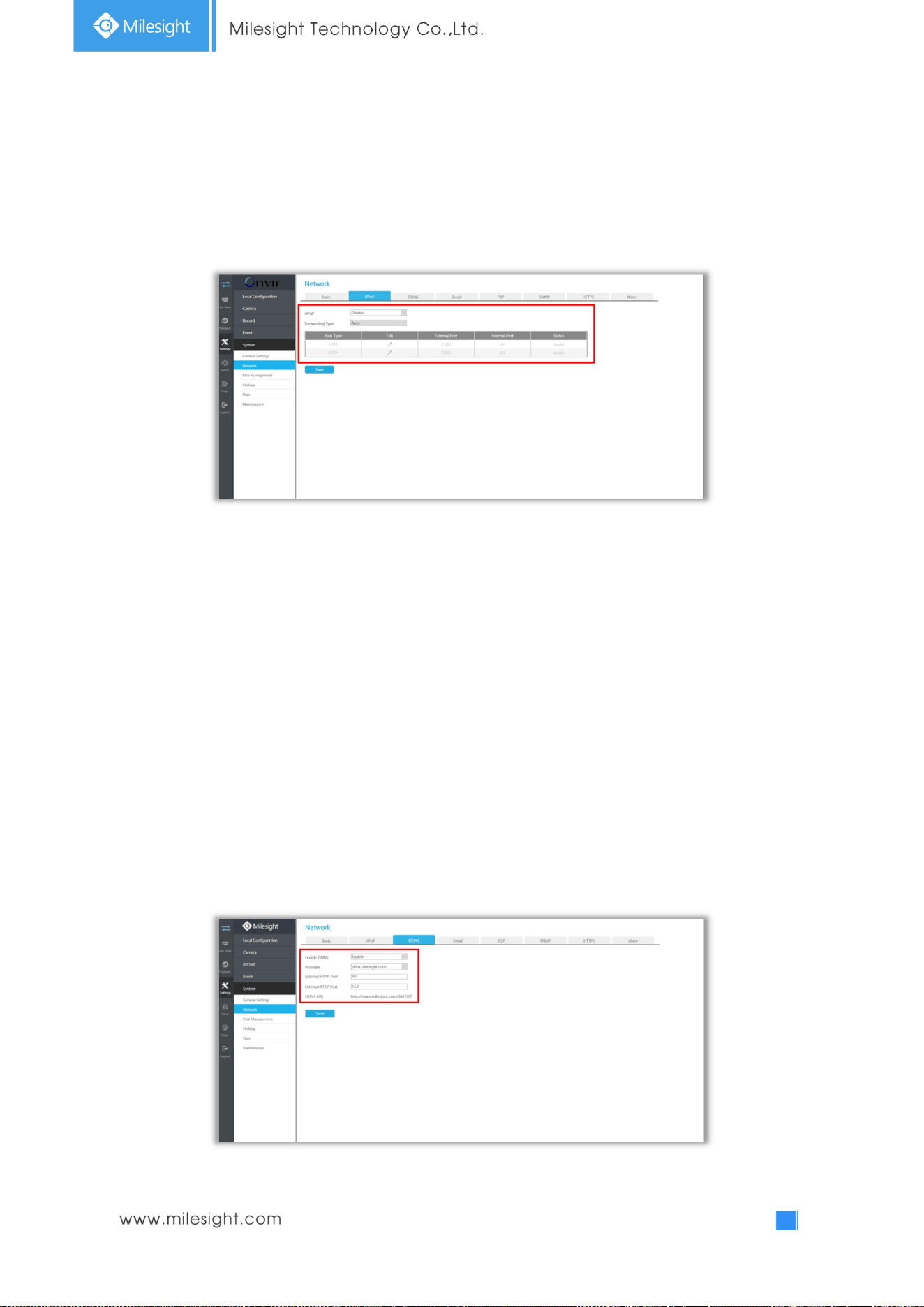
116
4.5.5.2.2 UPnP
With the function enabled, you don’t need to configure the port mapping for each port in router, it
will do the port mapping in router automatically once router supports UPnP.
4.5.5.2.3 DDNS
Using DDNS to solve the dynamic IP address problem.
Check DDNS check-box to enable it, then select a DDNS Server, input the user name, password and
host name. Do not forget to save the configuration.
Milesight has its own DDNS server. Please do port forwarding for HTTP port and RTSP port before
enabling Milesight DDNS. Then input corresponding information and you can use
http://ddns.milesight.com:MAC to access device remotely.
Note: “Host Name” must begin with letters, and it can only contain number, letters, and
hyphen.
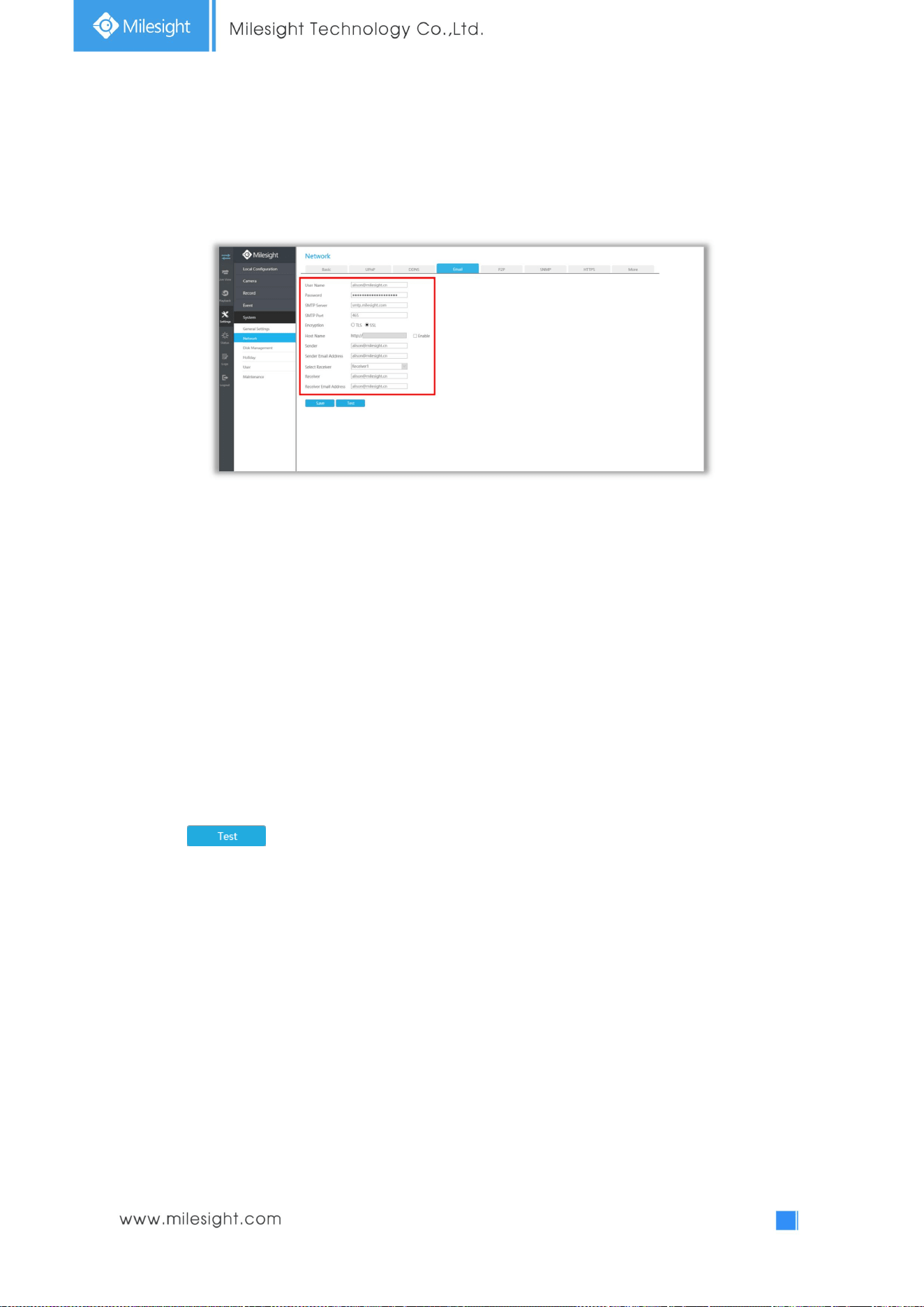
117
4.5.5.2.4 Email
Email will send receivers a screenshot when the alarm is triggered.
User name: The E-mail address you choose to send emails. Please input full email address into it.
Password: The password of the E-mail.
SMTP Server: The SMTP Server of your E-mail.
SMTP Port: The port of SMTP Server, it’s usually 25.
Encryption: Security Protocol of email sending, including TLS and SSL.
Host Name: It will be attached in the email.
Sender: Named by yourself for the Sender E-mail.
Sender Email Address: It must be same with [User name].
Select Receiver: You can have 3 receivers at most.
Receiver: Named by yourself for the Receiver E-mail.
Receiver Email Address: E-mail Address for the receivers.
Select to check if the Mail function is workable.
Note: If your NVR has a port forwarding IP for Host Name, please input the complete address
that contains the port.
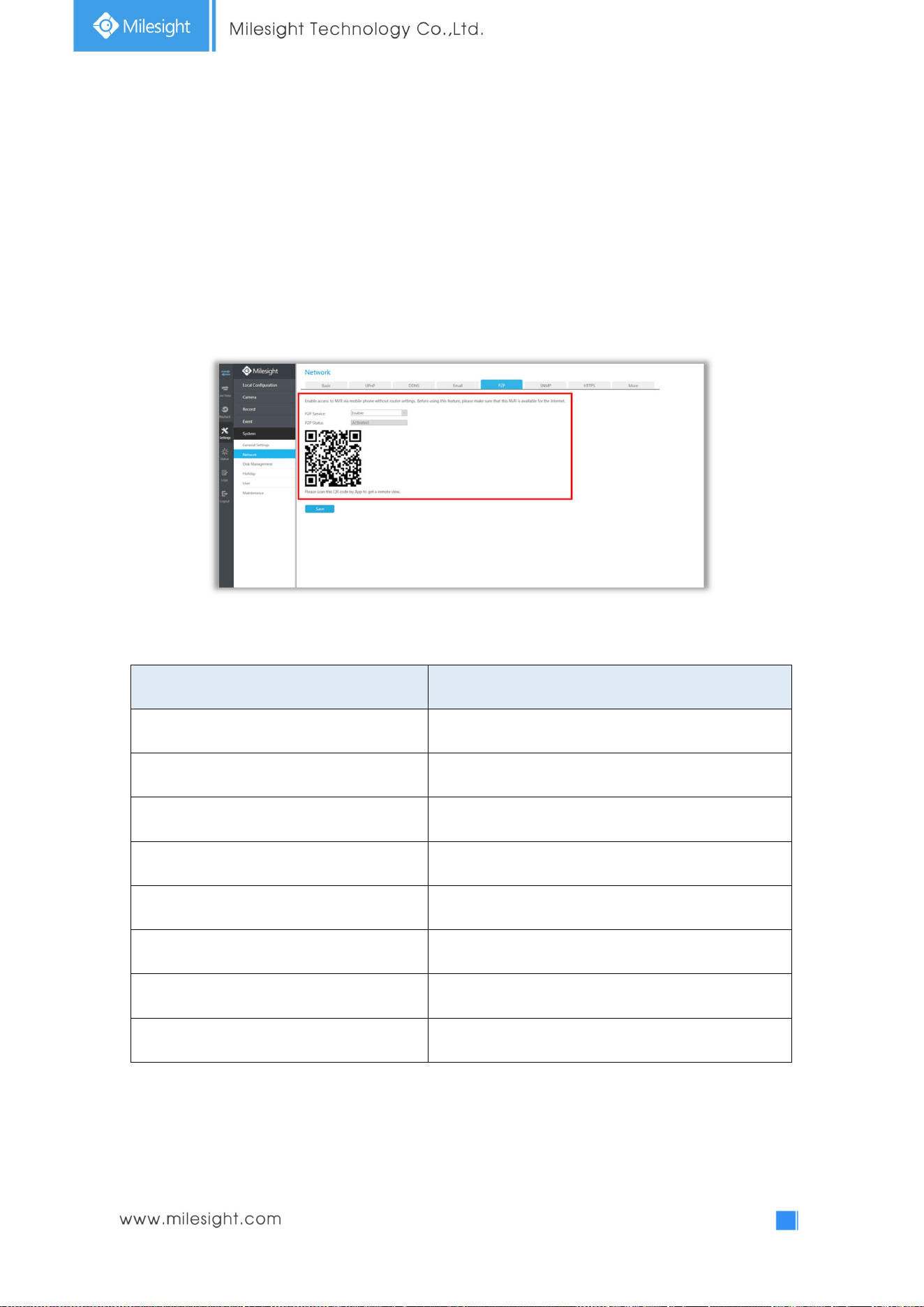
118
4.5.5.2.5 P2P
You can watch remote NVR live view in WAN by P2P on M-Sight Pro without doing port forwarding on
router.
Click “Enable” and “Save” to enable P2P.
P2P is enabled successfully when P2P Status shows “Activated”.
After enabling, you can add the NVR on the APP M-Sight Pro for live view via scanning the QR code on
the “P2P” page directly, or inputting the MAC address manually.
There are several status shows on P2P Status after clicking Saving, please check corresponded
possibilities below:
P2P Status Description
Network unavailable Failed to connect with internet
Authentication request failed Failed to authenticate P2P encryption
No idle UUID Please contact Milesight if this status shows up
Activated P2P is available
Login failed Failed to login P2P server
Initialization failed Failed to initialize P2P
Unactivated P2P is disabled
Unknown error Other error
Note:
1. Please make sure that NVR is available for internet before enabling.
2. If your NVR firmware version is not 7x.7.0.9-r2 or above, please contact Milesight to registered
P2P first.
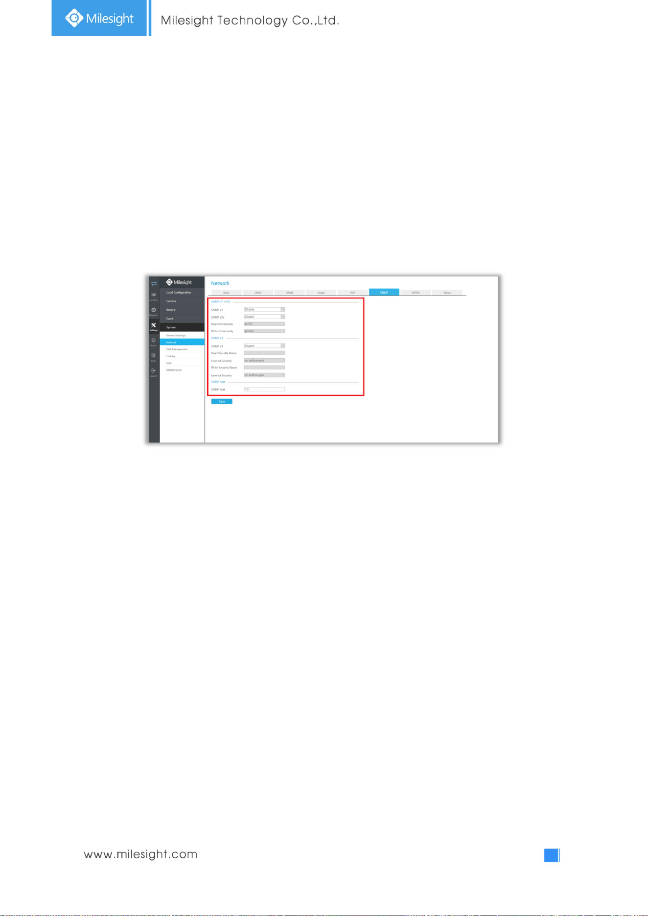
119
4.5.5.2.6 SNMP
SNMP is an abbreviation of Simple Network Management Protocol, which is convenient for NVR to be
monitored and managed in the whole network environment. The SNMP is widely used in many
network devices, software and systems.
Before setting the SNMP, please download the SNMP software and manage to receive the NVR
information via SNMP port. By setting the Trap Address, the NVR can send the alarm event and
exception messages to the surveillance center.
SNMP v1/2c/3: The version of SNMP, please select the version of your SNMP software.
SNMP v1: No security protection
SNMP v2c: Require password for access
SNMP v3: Support encryption on the premise that the HTTPS protocol must be
enabled
Read Community: Input the name of Read Community
Write Community: Input the name of Write Community
Read Security Name: Input the name of Read Security Community
Level of Security: There are three levels available: (auth, priv), (auth, no priv) and (no auth, no priv)
Write Security Name: Input the name of Write Security Community
Level of Security: There are three levels available: (auth, priv), (auth, no priv) and (no auth, no priv)
SNMP Port: The default of the SNMP port is 161
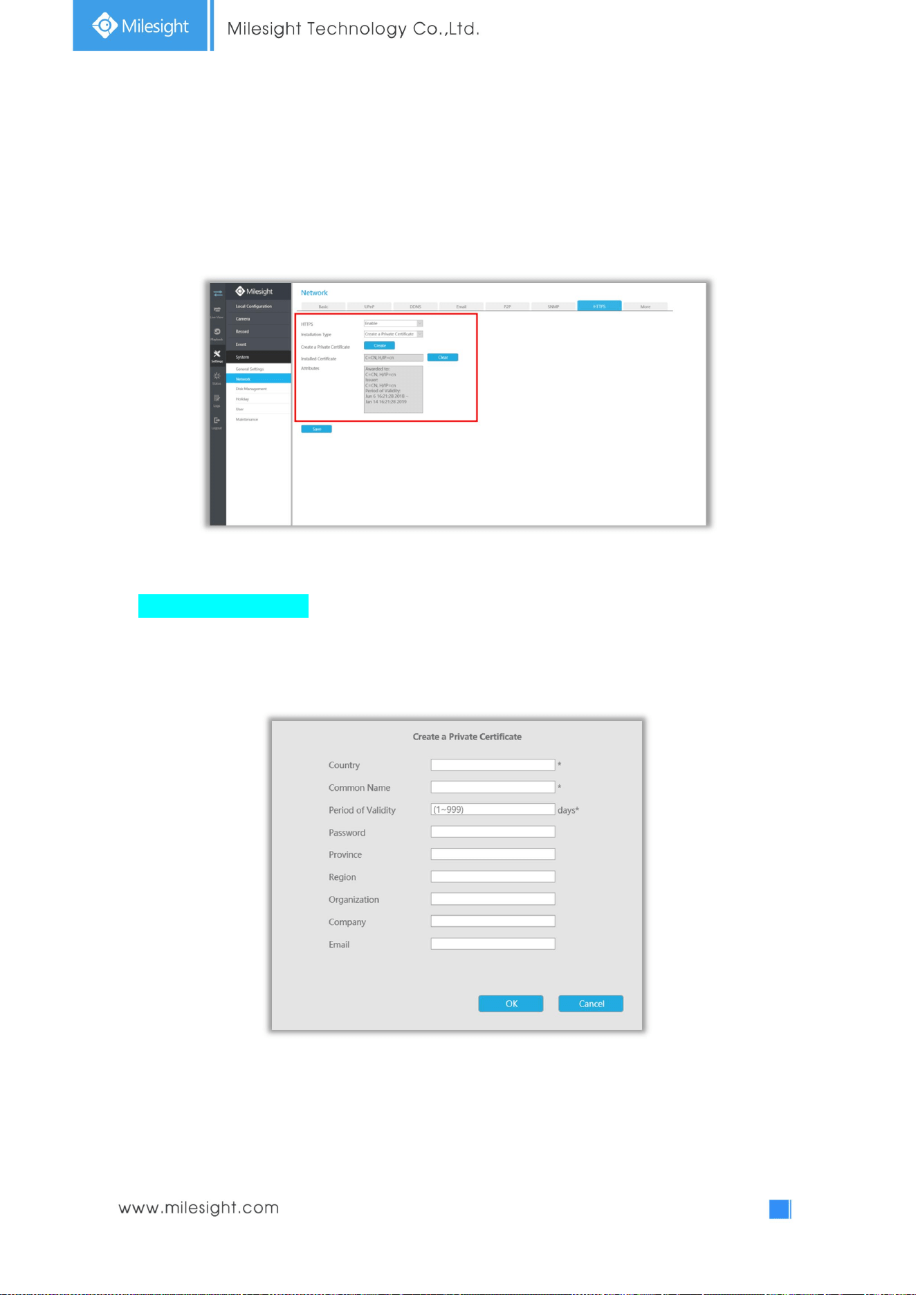
120
4.5.5.2.7 HTTPS
Set in the interface to make sure getting access to NVR successfully via HTTPS, which is able to
guarantee communication data security. The reliable and stable technology can secure the user
information security and device safety.
There are three certificate installation types:
Create a Private Certificate
Click “Create” to create the following dialog box. And then enter Country, Common Name, Period of
Validity and other information. And then click “OK” to generate a private certificate.
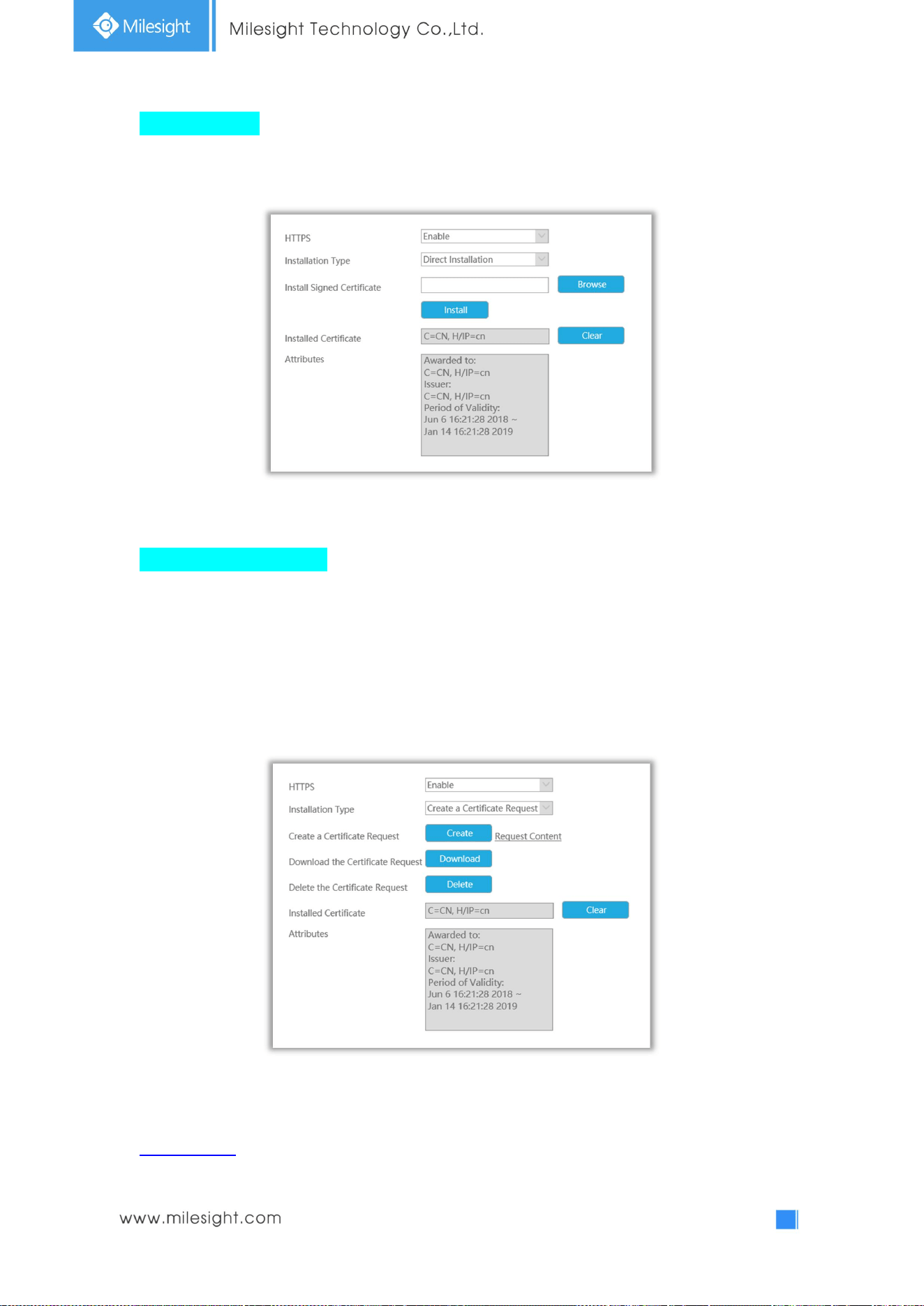
121
Direct Installation
Click “Browse” to select a signed certificate locally and click “Install” to install it.
Create a Certificate Request
Firstly, click “Create” button. And then enter Country, Common Name and other information to
create the certificate request;
Download the certificate request and submit it to the trusted certificate authority for signature;
After receiving the signed valid certificate, import the certificate to the device.
After creating and installing the certificate successfully, you can check the certificate information
and clear the information on the following interface. And you can access the NVR by inputting
https://ip:port via the web browser.
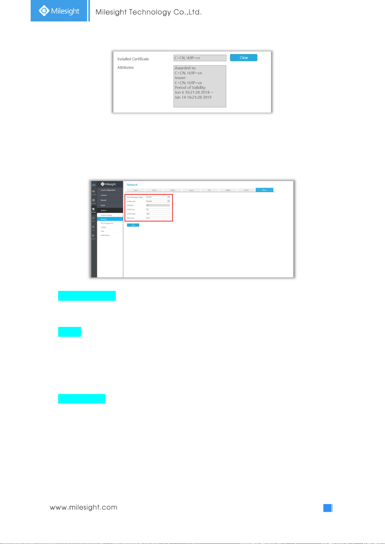
122
Note: The default HTTPS port is 443, you can modify it on the “More” interface.
4.5.5.2.8 More
Push Message Enable
With this option enabled, you can receive the alarm message on the mobile application.
SSH Port
Secure Shell (SSH) has many functions; it can replace Telnet, and also provides a secure channel
for FTP, POP, even for PPP.
Note: The default SSH port is 22. Only for Milesight R&D debugging.
HTTP Port Setting
The default HTTP port is 80. Please modify HTTP ports according to actual application.
Note:
1. The default HTTP port for IE browser is 80.
2. HTTP port is used for remote network access for 4k/H.265 NVR Series.
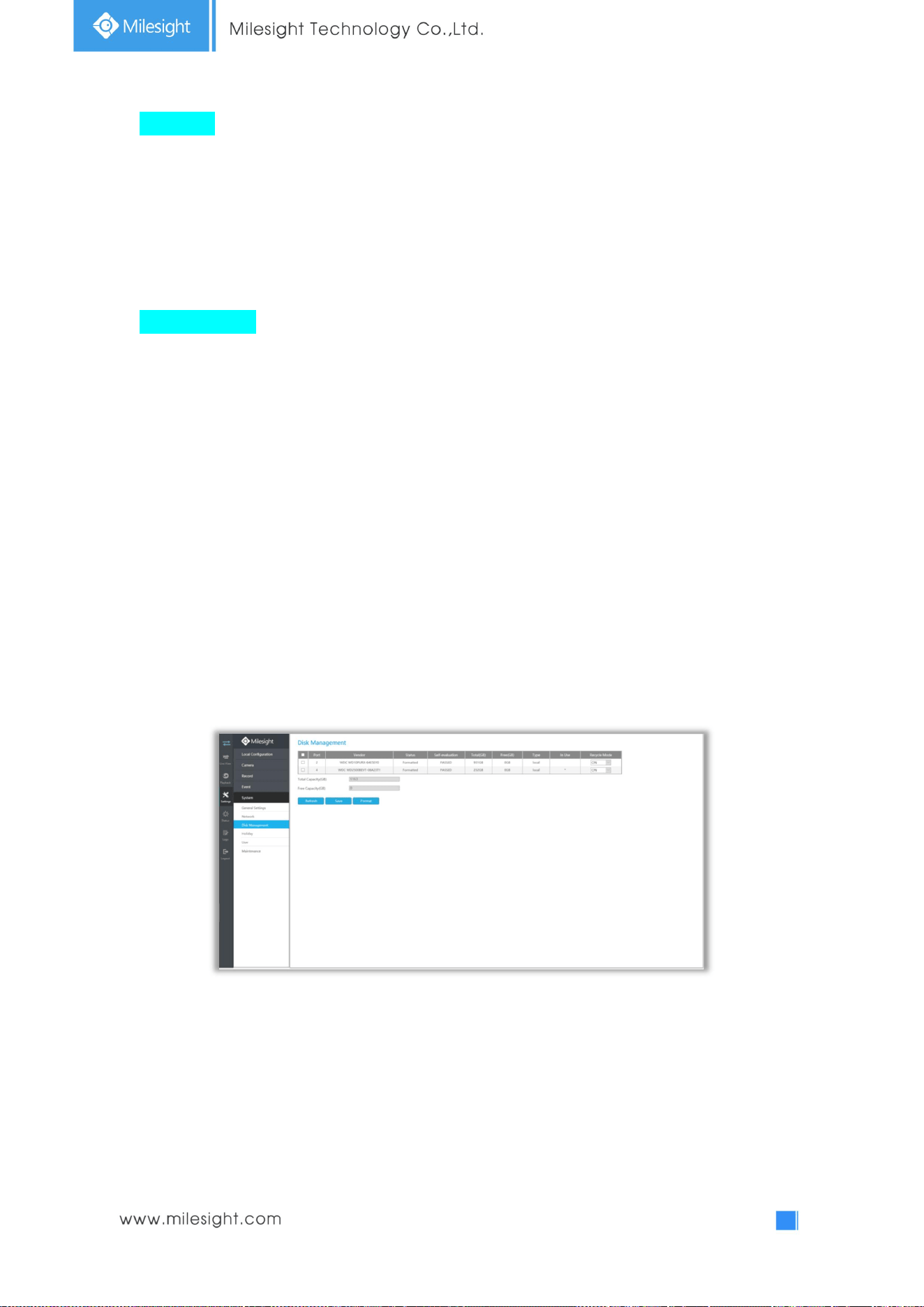
123
HTTPS Port
The default HTTPS port is 443. Please modify HTTPS ports according to actual application.
Note:
3. The default HTTPS port for IE browser is 443.
4. HTTPS port is used for remote network access for 4k/H.265 NVR Series.
RTSP Port Setting
Real Time Streaming Protocol (RTSP) is an application layer protocol in TCP/IP protocol system.
The default RTSP port is 554. Please modify RTSP port according to actual application.
Note:
1. RTSP port is used for remote network live view.
2. RTSP port valid range is 554 or 1024~65535.
4.5.5.3 Disk Management
Disk Management page contains the basic information of the disk. Select a disk and click [Format] to
format the disk.
Recycle Mode: HDD will rewrite data when Recycle Mode is ON.
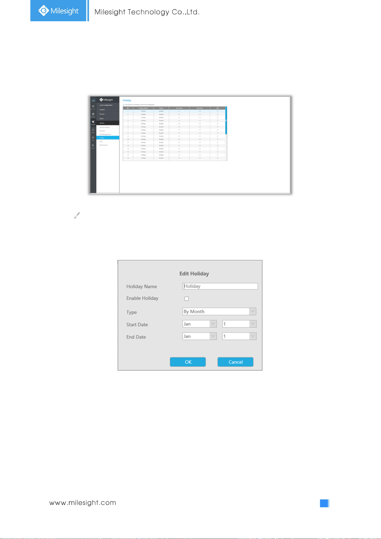
124
4.5.5.3 Holiday
It can configure the record or image capture schedule for holidays of the current year.
Click to open holiday configuration page to modify holiday name, check the ‘Enable Holiday’
check-box, and then select [Type] to setup Start/End date. There are By0 Month, By Week, and By
Date in [Type] mode. Then click [OK] to save the configuration and return to holiday page.
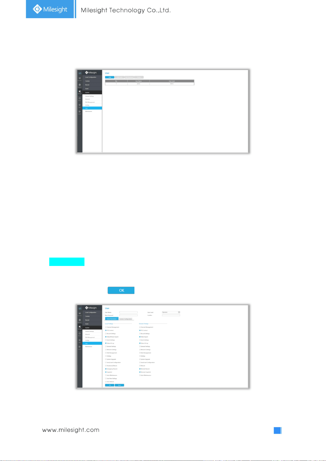
125
4.5.5.4 User
Note:
1. If the NVR firmware version out of the factory is xx.7.0.6 or above, the default user name
is “admin” and the default password is “ms1234”;
2. If the NVR firmware is upgraded to xx.7.0.6 or above from a lower version, the default
password will turn to “ms1234” after a reset, or it will keep the old default password
“123456”;
3. If the NVR firmware version is below xx.7.0.6, the default user name is “admin” and the
default password is “123456”.
Add a new user
Click [Add] to enter the user add menu, input information for the new user, select user level and set
user privileges, then click to save settings.
Note: User name can only contain letters and number. There are two user levels with different
authority: Operator and Viewer.
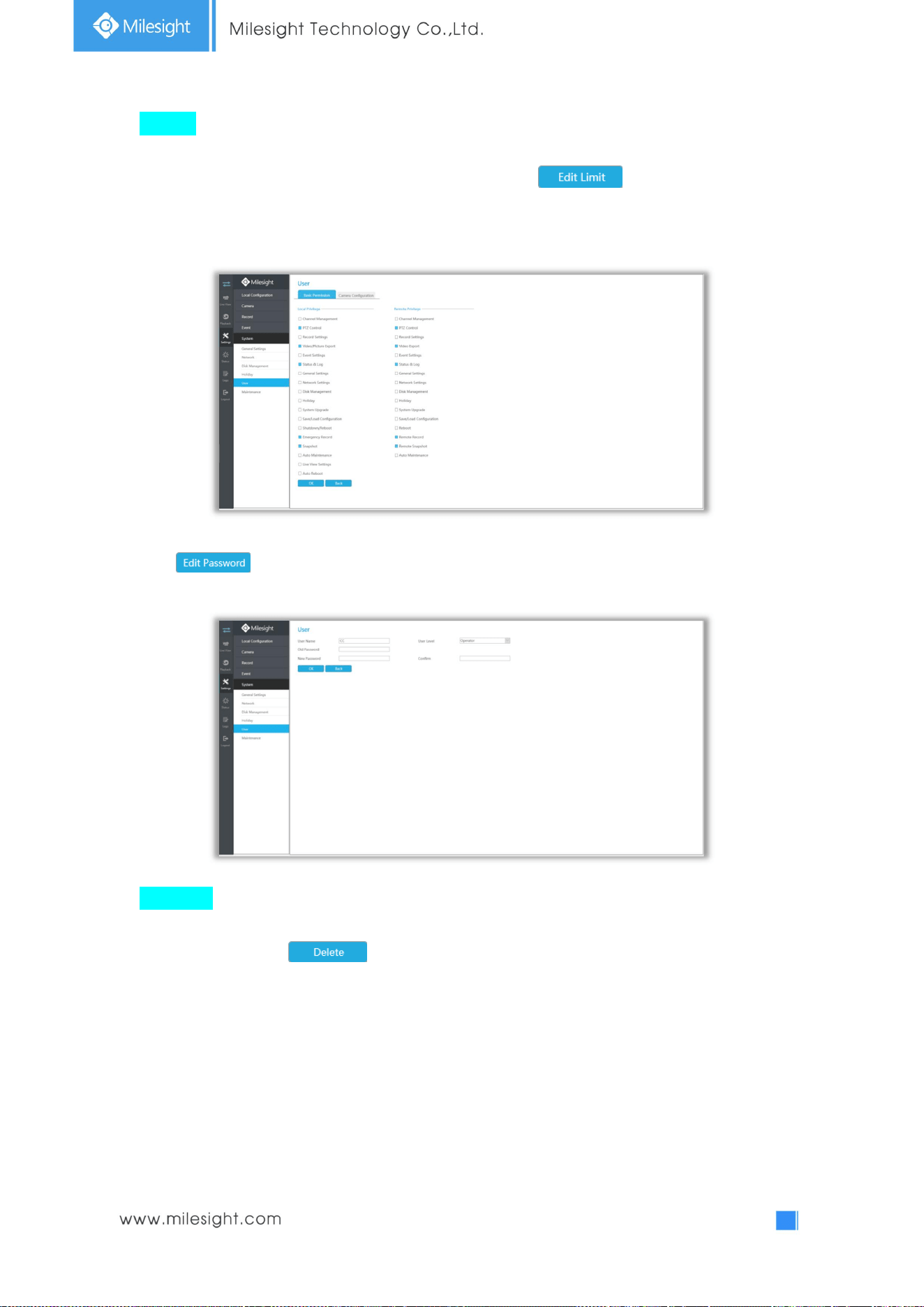
126
Edit user
Click a user, when the background color changes into blue, click to edit user privileges.
① Local Privilege means the privilege to the monitor connected with NVR
② Remote Privilege means the privilege to web settings.
Click to change password.
Delete user
Select a user and click to delete a user.
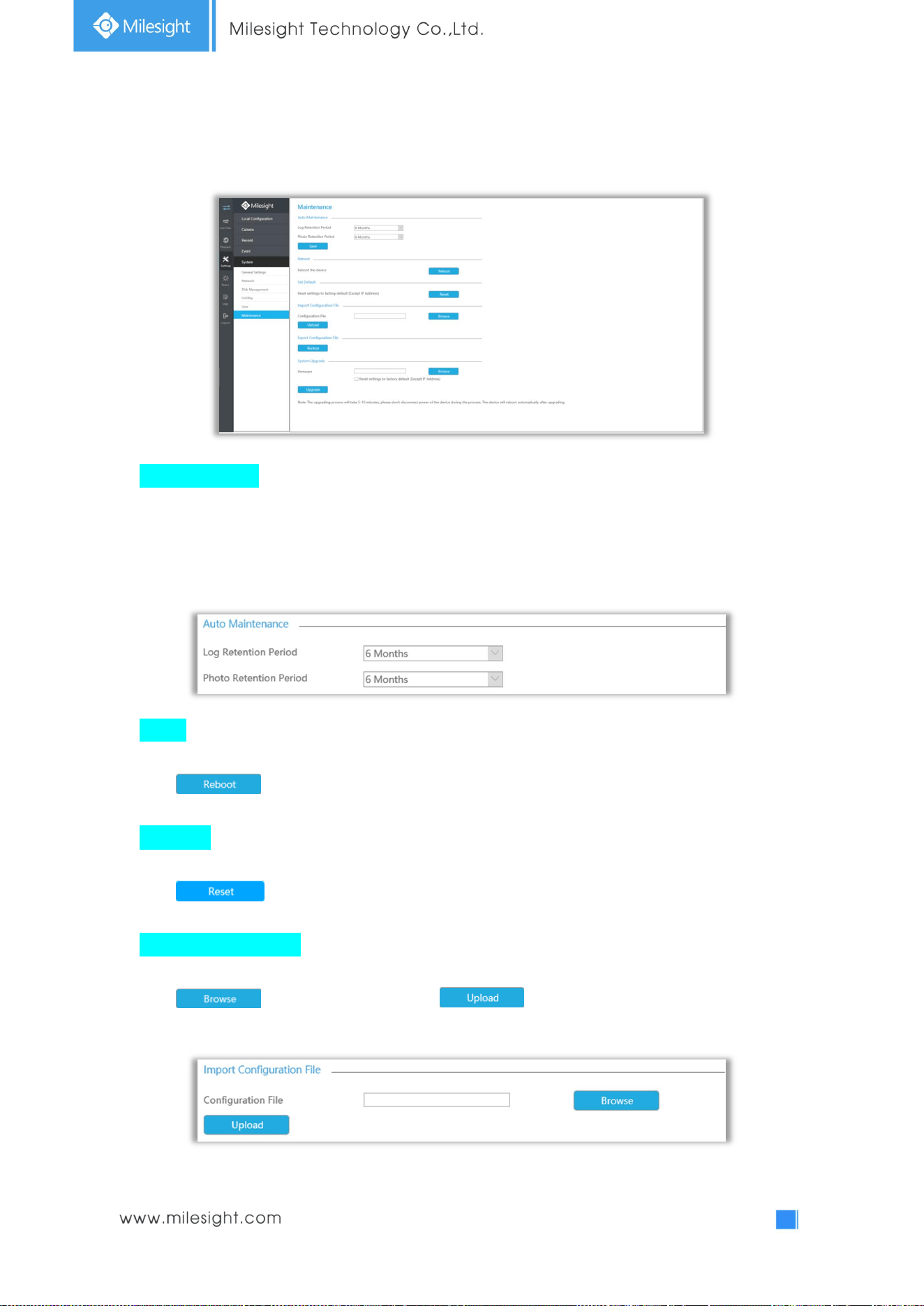
127
4.5.5.5 Maintenance
Auto Maintenance
You can set the Log and Photo Retention Period which is from 1 to 12 months or permanent.
According to your configuration, the NVR will automatically delete your logs and photos after the
retention period or permanently keep the Log and Photo.
Reboot
Click to reboot the NVR.
Set Default
Click to reset the NVR to factory defaults(Except IP Address).
Import Configuration File
Click to select one file and click to import the NVR configuration.
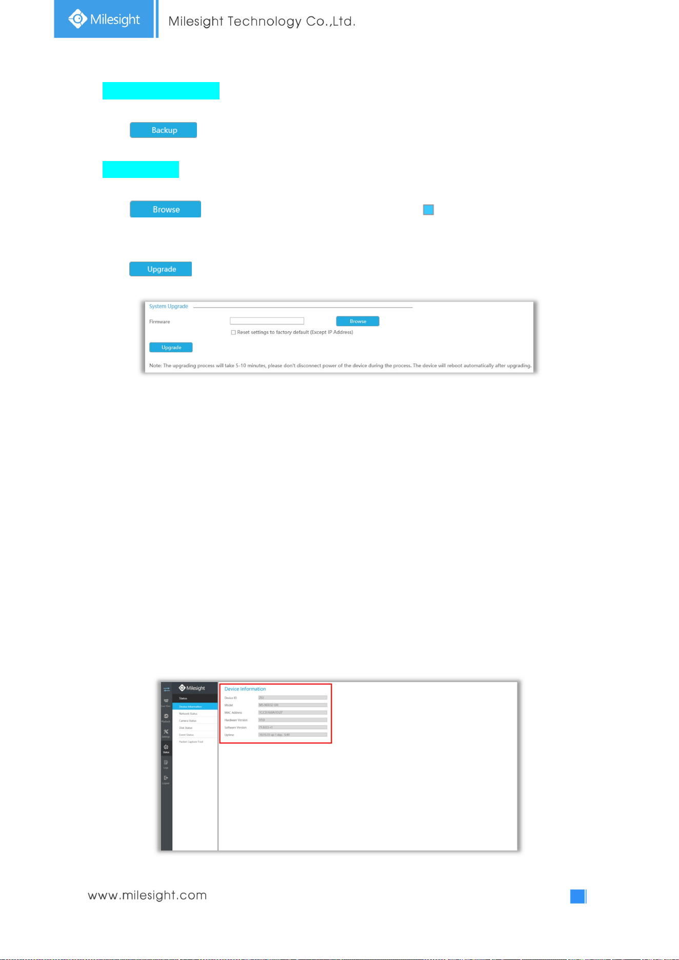
128
Export Configuration File
Click to backup current NVR settings.
System Upgrade
Click to select the firmware file, and you can check to reset configuration to
factory defaults.
Click to upgrade.
Note: It will take 5 to 10 minutes to upgrade, please do not disconnect the device power during
the process. The device will reboot automatically after upgrading.
4.6 Status
You can have a quick view of the information of the device, network, camera, disk and event. This part
is only for your rapid reference. If you want to make any configuration, please go to corresponding
interfaces accordingly.
4.6.1 Device Information
Device information includes Device ID, Model, MAC Address, Hardware Version, Software Version and
Uptime.
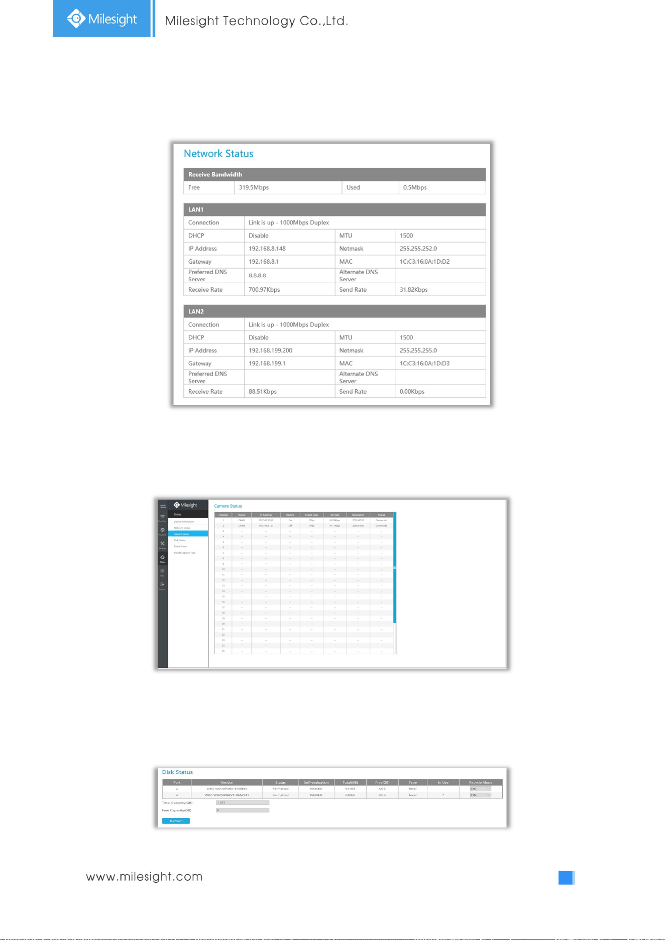
129
4.6.2 Network Status
Network Status includes three main parts: Receive Bandwidth, LAN1 and LAN2.
4.6.3 Camera Status
Camera status includes Channel, Name, IP Address, Record, Frame Rate, Bit rate, Resolution and
Status.
4.6.4 Disk Status
Disk status includes Port, Vendor, status, Total(GB), Free(GB), Type, In Use and Recycle Mode. You also
can check the Total Capacity (GB) and Free Capacity.
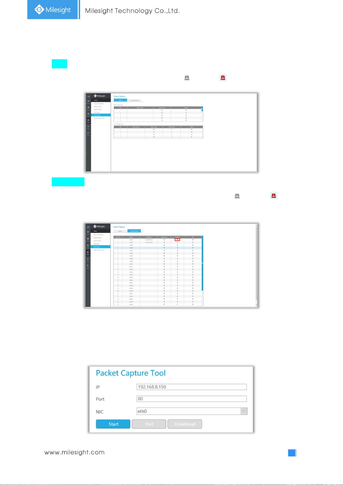
130
4.6.5 Event Status
Alarm
Alarm shows the Alarm Input and Alarm Output status. turns into when alarm is triggered.
Camera Event
Camera Event shows camera event, including Video Loss, Motion and I/O. turns into when
alarm is triggered.
4.6.6 Packet Capture Tool
Input IP and Port,then click [Start] to start capture and click [End]to stop. Click [Download] to backup
the captured packet locally.
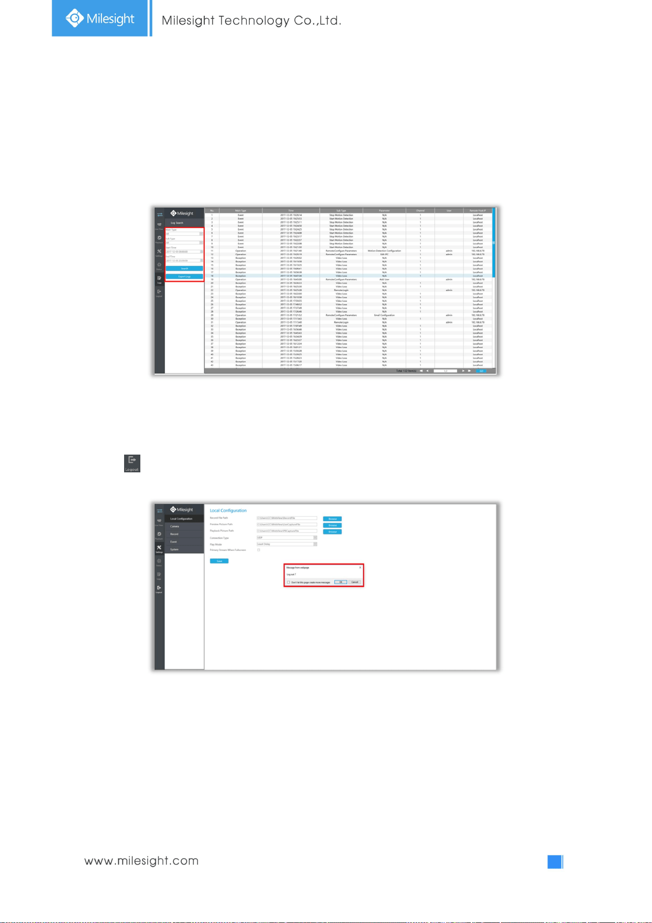
131
4.7 Logs
In Log interface, you can check, search and export logs. By selecting the Main Type , Sub Type, Start
Time and End Time which can narrow down the scale of logs, you can search for logs that you need
and then export them locally.
4.8 Logout
Click to exit the current account.

132
5.Services
Milesight Technology Co., Ltd provides customers with timely and comprehensive technical support
services. End-users can contact your local dealer to obtain technical support. Distributors and resellers
can contact directly with Milesight for technical support.
Technical Support Mailbox: support@milesight.com
Web: http://www.milesight.com
Online Problem Submission System: http://www.milesight.com/support/feedback.asp
MILESIGHT USA
TEL: +1-800-561-0485
Add: 7509 N.W. 36
th
Street, Miami, Florida 33166, USA
MILESIGHT KOREA
TEL: +82-2-839-3335
Add: 9F/901, Star Valley B/D Digital-ro 9gil 99, Geumcheon-gu, Seoul, Korea
MILESIGHT CHINA
TEL: +86-592-5922772
Add: No.23 Wanghai Road,2nd Software Park, Xiamen, China
Milesight
Better Inside, More in Sight

133