600A BOOSTER CABLES 25MM² X 3.5M WITH
ELECTRONICS PROTECTION
MODEL NO: BC25635SR
Thank you for purchasing a Sealey product. Manufactured to a high standard, this product will, if used according to these instructions,
and properly maintained, give you years of trouble free performance.
IMPORTANT: PLEASE READ THESE INSTRUCTIONS CAREFULLY. NOTE THE SAFE OPERATIONAL REQUIREMENTS, WARNINGS & CAUTIONS. USE
THE PRODUCT CORRECTLY AND WITH CARE FOR THE PURPOSE FOR WHICH IT IS INTENDED. FAILURE TO DO SO MAY CAUSE DAMAGE AND/OR
PERSONAL INJURY AND WILL INVALIDATE THE WARRANTY. KEEP THESE INSTRUCTIONS SAFE FOR FUTURE USE.
1. SAFETY
1.1. GENERAL SAFETY
WARNING! Modern vehicles contain extensive electronic systems.
YouarerequiredtocheckwiththevehicleManufacturer,foranyspecicinstructionsregardingtheuseofthistypeofequipmenton
each vehicle.
9 Familiariseyourselfwiththeapplication,limitationsandpotentialhazardsrelatingtothisproduct.Also,refertothevehicle
manufacturer`s handbook.IFINANYDOUBTCONSULTANELECTRICIAN.
9 Ensurethattheboostercablesareingoodorderandconditionbeforeuse.Ifinanydoubtdonotusetheunitandcontactanauto
electrician.
8 DO NOTdis-assembletheBoostercablesforanyreason.Theboostercablesmustbecheckedonlybyqualifiedservicepersonnel.
8 Onlyuserecommendedattachmentsandparts.Touseunapproveditemsmaybedangerousandwillinvalidateyourwarranty.
WARNING!Checkthatbothvehiclebatteriesarethesamevoltage.
9 Ensurethatvehiclesarenottouchingbeforeattemptingtousetheseleads.
9 Keeptoolsandotheritemsawayfromtheengine,andensurethatyoucanseethebatteryandtheworkingpartsoftheengine
clearly.
9 Keep children and unauthorised persons away from the work area.
9 Ensurethatthejumpleadsarenottangledandareclearofmovingorhotengineparts.
8 DO NOTallowtheclampstotoucheachotherortomakecontactwiththevehiclebodywork,asthismayresultinarcing.
8 DO NOTcrossconnectthepowerleadstothebattery.Ensurepositiveistopositiveandnegativeistonegative.
8 DO NOT pull the cables or clamps from the battery terminals.
8 DO NOToperateinthevicinityofflammableliquidsorgases.
8 DO NOT try to jump start a frozen battery.
8 DO NOT use or store the booster cables in damp or wet locations.
8 DO NOTusethisproducttoperformataskforwhichitisnotdesigned.
9 Thecablesmaybecomehotwithexcessiveuse.Ifso,allowafewminutesforthemtocoolbeforeattemptingtore-use.
9 Ifthesurgeprotectionunitreceivesasharpknockorblow,theunitmustbecheckedbyaqualifiedserviceagentbeforenextuse
9 When not in use, store the booster cables carefully, in the case provided, in a safe, dry, childproof location.
1.2. PERSONAL PRECAUTIONS
9 EnsurethatHealth&Safety,localauthority,andgeneralworkshoppracticeregulationsareadheredtowhenusingthisequipment
9 Ensurethatthereisanotherpersonwithyouespeciallywithinhearingrangeofyourvoice,orcloseenoughtocometoyouraid
shouldaproblemarisewhenworkingnearalead-acidbattery.
9 Removepersonalmetallicitemssuchasrings,bracelets,necklacesandwatches.Alead-acidbatterycanproduceashort-circuit
currenthighenoughtoweldaringortheliketometal,whichmaycausesevereburns.
9 Ensurethathandsandclothing(especiallybelts)areclearoffanbladesandothermovingorhotpartsofengine,removetiesand
containlonghair.
9 Wearsafetyeyeprotectionandprotectiveclothing.Avoidtouchingeyeswhileworkingnearbattery.
8 DO NOTsmokeorallowasparkorflameinthevicinityofbatteryorengine.
8 DO NOT drop any metal tool onto the battery as It may spark or short circuit the battery which could cause an explosion.
8 DO NOTusewhilstundertheinfluenceofdrugs,alcoholorintoxicatingmedication.
2. INTRODUCTION
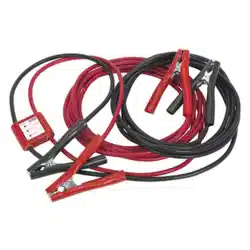
TheBoosterCablesconsistofPVCsheathedcoppercoatedaluminiumcableswhichgivemaximumpowertransferyetremainexibleand
resistanttooil,greaseandmostacids.Insulatedheavy-dutyclampsreducetheheatingeffectofpowertransfer.TheunitfeaturesanLED
displayunitwhichshowsthebatteryvoltageandincludesareversepolarityindicatorandalarm.Inlinesurgeprotectorhelpstoprevent
electricalspikesoccurring.Additionalfeaturesincludealternatorchargecheckandbatteryconditioncheckandissuppliedinacarrycase.
3. SPECIFICATIONS
Model No: ........................................................... BC25635SR
CableSection: ............................................................. 25mm
2
Length: ........................................................................... 3.5m
Capacity: ........................................................................ 600A
BC25635SRIssue2(HF)11/5/21
Original Language Version
©JackSealeyLimited
Refer to
Instruction
Manual
Wear Eye
Protection
Wear
Protective
Gloves
Warning!:
Explosive
Risk
Warning!:
Electricity
Warning!:
Corrosive

4. OPERATION
4.1. CONNECTING BOOSTER CABLES
4.1.1. Startingwiththeclampsattheendnearesttothesurgeprotector,attachthered(positive)clamptothepositiveterminalofthe
chargedbattery.
4.1.2. Connectingthesecondred(positive)clamptothepositivebatteryterminalofthevehiclesatbattery.
4.1.3. ConnectBlack(negative)clampattheendnearesttothesurgeprotector,tothenegativeterminalofthechargedbattery.
4.1.4. Finallyconnecttheblack(negative)clamptoanunpaintedpartofthechassisorengineonthevehiclewiththeatbattery.
Warning!ensurethattheconnectionpointisnotnearthebattery,carburettor,fuelorbrakepipestominimizeanyreriskthatcould
becausedbysparking.
4.2. STARTING THE VEHICLE
4.2.1. Ensurethatallleadsareclearofallmovingorhotparts.
4.2.2. Startengineofvehiclewithchargedbatteryandletrunforaminute.
4.2.3. Trytostartthevehiclewiththeatbatteryifitstartsrunforoneminutethenremovethecables.
4.2.4. Ifthecablesbecomehotswitchoffbothvehiclesandallowtocooldownbeforeattemptingtorestartthevehicle.
4.3. DISCONNECTING THE BOOSTER CABLES
4.3.1. Turnofftheenginewiththechargedbattery
4.3.2. Thenremovethecablesinreverseordertothatdescribedin4.1
WARNING!Takecaretokeepclearofallmovingandhotparts.
4.4. BATTERY CONDITION INDICATOR
4.4.1. TheVoltageindicatordisplaysthevoltagewhenthevehicleengineisnotrunning.
4.4.2. Areadingof10.5Voltsona12Vbatteryor22Voltsona24Vbattery-indicatesbatteryverylowinchargemaybedamagedandnot
be able to start vehicle.
4.4.3. Areadingof11.5Voltsona12Vbatteryor23.5Voltsona24Vbattery-indicatesthebatteryneedschargingormaybedamaged.
4.4.4. Areadingof12.3Voltsona12Vbatteryor24.3Voltsona24Vbattery-indicatesthatthebatteryisfullychargedandingood
condition.
4.5. TESTING THE BATTERY CONDITION
4.5.1. Insulatethepositiveandnegativeclampsnearestthevoltagedisplaybyclampingtoanonconductivematerial.
4.5.2. Connecttheotherpositiveclamptothepositiveterminalofthevehiclebattery,thenconnectthenegativeclamptothenegative
terminal of the battery.
4.5.3. WhentheboostercablesareconnectedthevoltagewillbedisplayedontheLEDindicator.
4.5.4. Havingconrmedthebatteryconditionremovethecablesinreverseorder.
4.6. ALTERNATOR CHARGING CHECK
4.6.1. Thealternatorfunctioncanbecheckedtoseeifitischargingthebatteryatthecorrectrate.Connecttheclampsasdescribedin
4.5above.
4.6.2. StarttheengineandmonitorthevoltageontheLEDindicator.
4.6.3. Inmostcasesthealternatorwillbefunctioningcorrectlyifthedisplayindicates13.7-14+Voltsona12Vbatteryor24.7-25+Volts
ona24Vbattery.Checkmanufacturesspecicationsforrechargevoltagesaschargingabove14Voltsfor12Vbatteryandabove
25Voltsfor24Vbatteryindicatesapossiblefaultinthealternatorthisshouldbecheckedbyanautoelectrician.
4.6.4. Removeclampsinreverseorder.
4.7. REVERSE POLARITY LED INDICATOR
4.7.1. TheLEDindicatorilluminatesredandomitsanaudibletonewhentheboostercablesareincorrectlyconnectedtothecharged
battery if this happens reverse the leads. If the LED is not illuminated and there is no audible tone continue to connect leads as
described above.
5. TROUBLESHOOTING
Problem Causes Solutions
FlatBatteryvehiclewillnotturnover Insufcient/badboostercableclamp
connection
1.Reconnecttheboostercablesasin
instructions.
2.Checkthebatteryterminalsare
corrosion free if not clean and reconnect.
Booster cables connected incorrectly Check if the reverse polarity LED is
illuminated(red)andanaudibletonecan
beheard.Ifsodisconnectclampsandret
as instructions.
BoosterCablegetshot Incorrectboostercablesbeingused CheckthethevehiclesbatteryAMPrating.
ChangethecablestothecorrectAMPtype
if incorrect
Thevehiclesmanagementsystemmaynot
beworkingcorrectlyandmaybestopping
thevehiclefromstarting.Excessive
crankingoftheengineermaycausecables
togethot.
Stoptryingtojumpstartthevehicleand
consult automotive electrician.
Original Language Version
©JackSealeyLimited
BC25635SRIssue2(HF)11/5/21

Original Language Version
©JackSealeyLimited
BC25635SRIssue2(HF)11/5/21
Sealey Group, Kempson Way, Suffolk Business Park, Bury St Edmunds, Suffolk. IP32 7AR
01284 757500 01284 703534 sales@sealey.co.uk www.sealey.co.uk
Note:Itisourpolicytocontinuallyimproveproductsandassuchwereservetherighttoalterdata,specificationsandcomponentpartswithoutprior
notice.
Important: No Liability is accepted for incorrect use of this product.
Warranty:Guaranteeis12monthsfrompurchasedate,proofofwhichisrequiredforanyclaim.
ENVIRONMENT PROTECTION
Recycleunwantedmaterialsinsteadofdisposingofthemaswaste.Alltools,accessoriesandpackagingshouldbesorted,takento
arecyclingcentreanddisposedofinamannerwhichiscompatiblewiththeenvironment.Whentheproductbecomescompletely
unserviceableandrequiresdisposal,drainanyfluids(ifapplicable)intoapprovedcontainersanddisposeoftheproductandfluids
accordingtolocalregulations.
WEEE REGULATIONS
DisposeofthisproductattheendofitsworkinglifeincompliancewiththeEUDirectiveonWasteElectricalandElectronicEquipment
(WEEE).Whentheproductisnolongerrequired,itmustbedisposedofinanenvironmentallyprotectiveway.Contactyourlocalsolid
wasteauthorityforrecyclinginformation.