
RELAY G10TII / G10 / G10S
PILOT’S GUIDE
40-00-0569 - C www.line6.com/manuals © 2021 Yamaha Guitar Group, Inc. All rights reserved.
®


© 2021 Yamaha Guitar Group, Inc. All rights reserved.
Line 6, the Line 6 logo, and Relay are trademarks or registered trademarks of Yamaha Guitar Group, Inc. in the U.S. and/or other jurisdictions.
Supplier’s Declaration of Conformity
47 CFR § 2.1077 Compliance Information
Unique Identifiers: Line 6
®
Relay
®
G10TII, Line 6 Relay G10, Line 6 Relay G10R, Line 6 Relay G10S,
Line 6 Relay G10SR
Responsible Party - U.S. Contact Information:
Yamaha Guitar Group, Inc.
26580 Agoura Road
Calabasas, CA 91302-1921
(818) 575-3600
https://line6.com/
FCC Compliance Statement:
This device complies with Part 15 of the FCC Rules. Operation is subject to the following two
conditions: (1) This device may not cause harmful interference, and (2) this device must accept any
interference received, including interference that may cause undesired operation.
FCC ID: UOB-G10TII
IC: 6768A-G10TII

2
System Overview
• Wirelessfreedominanysizevenue,home,oroce
• Easy to use—no setup required
• Automatically chooses the best channel for true
playing freedom
• Up to 7 hours of playing time per charge
• Optional manual channel selection for setups with
multiple wireless units (Relay G10S and select Relay-
Ready products)
• Best in class sound quality provided by:
• 24-bit uncompressed digital transmission
• Best in class DAC and ADC provide super low noise
transmission (better than 110dB dynamic range)
• Up to 50 feet (15 meters) for Relay G10, or up to 130
feet (40 meters) for Relay G10S, line-of-sight range
2.4GHz Wireless
Since the Line 6 Relay is a 2.4GHz wireless system, please
avoid placing the receiver next to other RF transmitting
equipment. We recommend that you install the G10 or G10S
receiver at least 10 feet (3 meters) away from RF transmitters
(e.g., WiFi routers).
The Relay system automatically selects the best channel when
the transmitter is docked (for the G10S receiver, its Channel
Selector needs to be set to AUTO).
After changing WiFi or other 2.4GHz wireless channels, please
dock the transmitter in the receiver for at least 10 seconds.
What’s in the Box
RELAY G10TII
• Relay G10TII Transmitter
• Pilot's Guide and End User License Agreement
RELAY G10
• Relay G10TII Transmitter (not included in G10R
Receiver Separate)
• Relay G10 Receiver
• USB-A to Micro USB-B cable
• Universal USB Power Supply (5V-1A) kit with
international AC adapter kit (manufacturer: Hon-
Kwang Electric Co., Ltd. and model: HK-AP-
050AZZZ-CP [zzz=001 to 100] ). The provided AC
adapter serves as the disconnect device
• Pilot's Guide and End User License Agreement
RELAY G10S
• Relay G10TII Transmitter (not included in G10SR
Receiver Separate)
• Relay G10SR Receiver
3
• 9V DC Power Supply (manufacturer: Shenzhen
JingQuanHua & Everrise Intelligent Electric Co. Ltd.
and model: NSA5Ex-090050)
• USB-A to Micro USB-B Cable
• Pilot's Guide and End User License Agreement
Please refer to the additional included safety
documentation for power supply information.
(Direct current)
Getting Started
Using the Relay G10TII Transmitter with a Relay G10 or
G10S Receiver
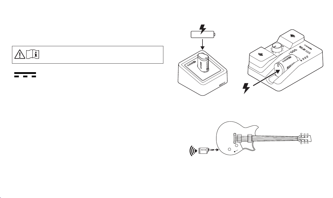
1. Insert the Relay G10TII transmitter all the way into the receiver
dock to allow the battery to charge. A green steady LED on
the transmitter indicates the transmitter is fully charged. A
full charge takes approximately 3 hours.
2. While the G10TII is docked in the receiver, the system scans the
environment and automatically selects the optimal wireless
channel.
The G10S receiver's channel selector must be set to
AUTO for this step.
Relay G10 Relay G10S
3. Insert the G10TII transmitter into your instrument.
4
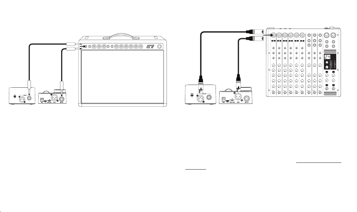
4. Connect the receiver to a power source using the power adapter
provided with your device. Connect the Relay G10 or G10S
receiver's 1/4" Instrument Output into an amp or FX unit.
Relay G10 Relay G10S
5. For use as a DI with bass and acoustic guitars, connect the Relay
G10 or G10S receiver’s XLR DI Out to a mixer or audio interface.
Relay G10
Relay G10S
Using a Relay G10TII Transmitter with Relay-Ready
Devices
In addition to being compatible with Line 6 wireless receivers,
the Relay G10TII transmitter also works with a number of
select Relay-Ready devices. Please see https://line6.com/
g10info/ for more info.
To use G10TII with your Relay-Ready device, please see the
following steps.
5
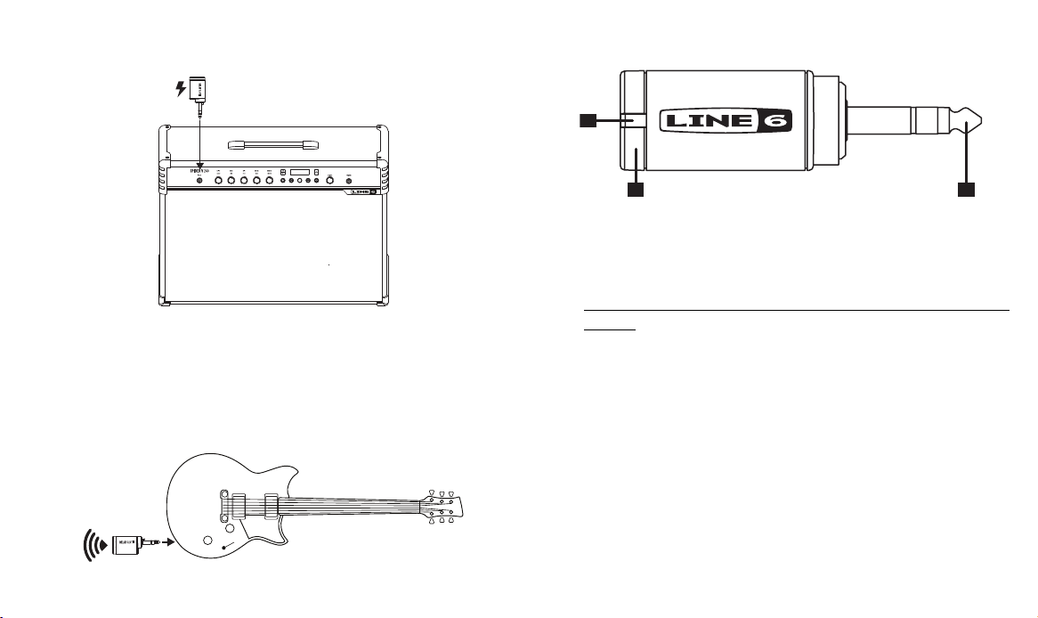
1. Power your Relay-Ready device on and insert the Relay G10TII
into the input jack.
The Relay-Ready device charges the G10TII transmitter,
as well as scans the environment, and automatically
selects the optimal wireless channel and frequency.
2. Once fully charged, insert the G10TII transmitter into your
instrument. Please refer to the documentation of your
Relay-Ready product for additional details.
Relay G10TII Transmitter Details
23
1
1. Battery Status - This LED illuminates green when the
transmitter is powered on and while more than 30 minutes
of operating time remains. The LED ashes red when
less than 30 minutes of operating time remain—also see
“Important Information About the G10TII Transmitter” on
page 6 for additional LED states.
When the transmitter is plugged into the receiver for
charging,aashingredLEDindicateslessthan30minutes
ofbatteryoperation,aashinggreenLEDindicatesmore
than 30 minutes of battery operation, and a steady green
LED indicates a fully charged transmitter. A full charge
takes approximately 3 hours.
2. 1/4" Plug - Plugs into instrument.
3. Antenna - The calibrated internal antenna avoids damage
or deformity in normal use. Avoid covering the antenna
area with metallic fabrics or accessories, and avoid direct
contact with parts of the performer’s body for best results.
6
Sleep Mode - To extend battery life, sleep mode is activated
after a period of 4 minutes where no audio input is detected.
The transmitter “wakes up” automatically when the instrument
is played.
Important Information About the G10TII Transmitter
• TherecommendedchargingtemperaturerangeoftheG10TIItransmitterisspeciedas50°Fto86°F(10°Cto30°C).
• TherecommendedoperatingtemperaturerangeoftheG10TIItransmitterisspeciedas32°Fto122°F(0°Cto50°C).
• Line 6 recommends charging the G10TII transmitter at least every 6 months, based on best practices for lithium-ion
batteries.
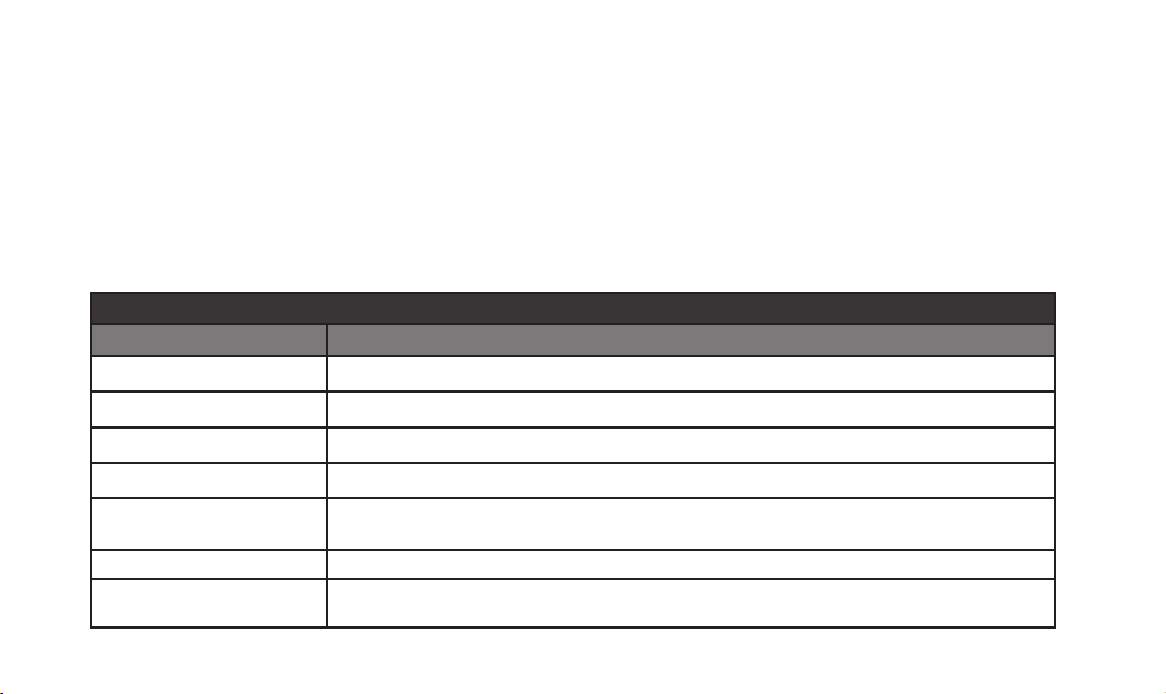
G10TII Transmitter (docked in receiver)*
LED State Condition
Red(slowash)
Charging, less than 30 minutes battery time remaining
†
Green(slowash) Charging, more than 30 minutes battery time remaining
Green (solid)
Fully charged
‡
DimRed/Pink,mayturno G10TII is not docked properly—Try un-docking and re-docking
Red(threequickashes)
G10TII charging has stopped due to being outside the supported temperature range—Charging
will resume after 5 minutes at
50°Fto86°F(10°Cto30°C)
§
Orange (solid) DockedandconnectedtoMacorPC,rmwareupdateinprogress
O
Receiver not powered (transmitter enters sleep mode after 4 minutes if receiver power is
disconnected)
7
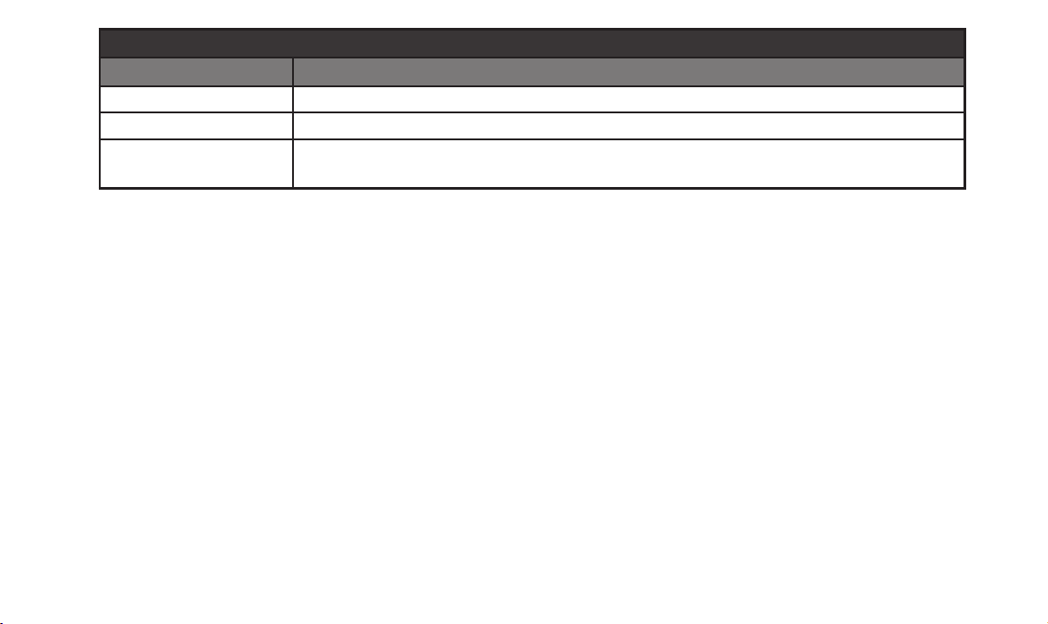
G10TII Transmitter (connected to instrument)
LED State Condition
Green (solid) Transmitting, more than 30 minutes battery time remaining
Red(slowash) Transmitting, less than 30 minutes battery time remaining
O
Connected to an instrument but not enough remaining battery power to transmit
‖
or removed from
instrument
* When the G10TII is docked in a receiver or Relay-Ready device, the G10TII LED initially indicates amber, red, or green,
dependingonitscurrentbatterystate.Thisisfollowedbyfourashes(red)asthedeviceinitializes.Oncethiscompletes,the
G10TII LED proceeds to indicate its remaining battery time.
†
All values stated for amount of battery time remaining are approximate, and the exact amount of battery time remaining
whenanLED stateisindicatedmay varyslightly betweencharges.When theG10TII ashesred,itmayhaveupto60
minutes of battery time remaining.
‡
IftheG10TIIreachesafullcharge(solidgreen)andremainsdocked,theG10TIILEDmayeventuallyashgreenagain.This
isexpectedbehaviorastheG10TIImaydischargeslightlyafterreachingafullcharge,anditsLEDmaythenashgreenuntil
it again reaches a full charge.
§
If the lockout indication continues for over 10 minutes, please stop charging and try again in a cooler environment condition.
‖
WhentheG10TIIhasinsucientpowertotransmit,itsLEDmayindicateapatternofvequickredasheswhenconnected
to an instrument and audio is detected. This is the expected behavior.
8
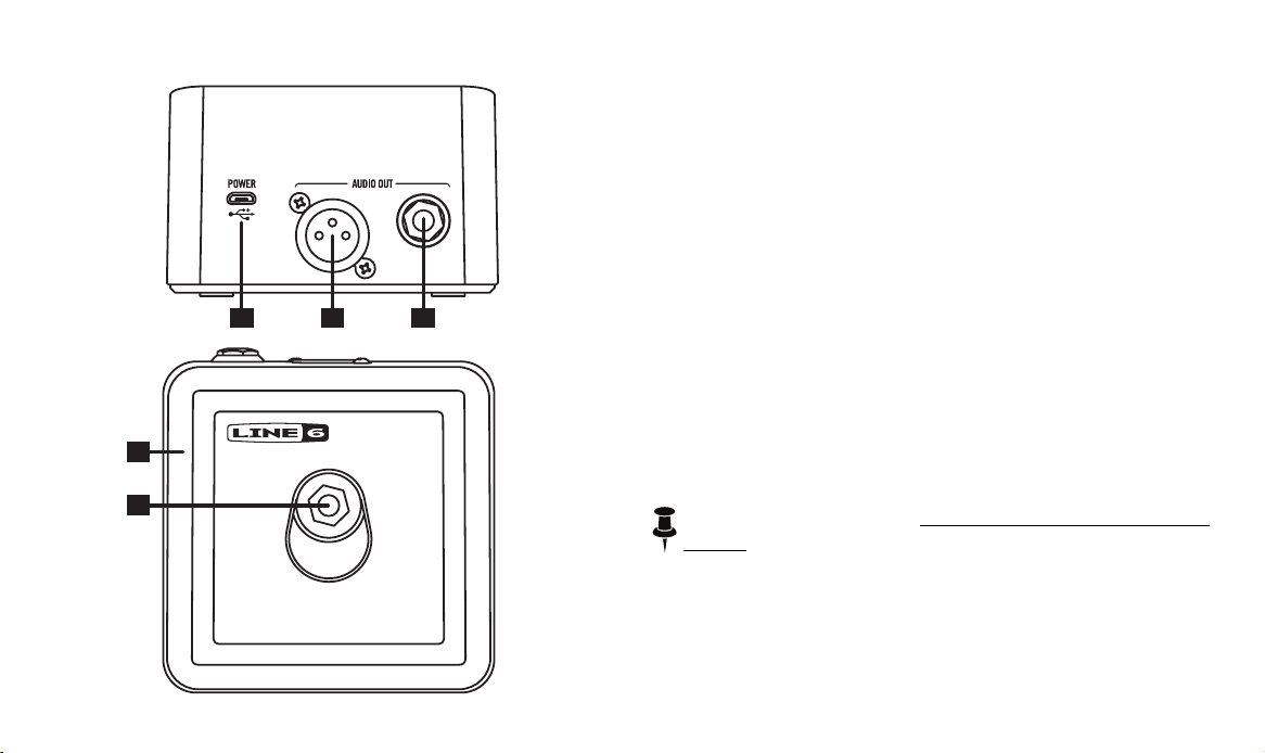
Relay G10 Receiver Details
4
1
5
23
1. Micro USB – Use for primary DC (5V DC /1A) power and
rmwareupdates.
2. Output A – ¼" unbalanced, full performance output
intended to drive a guitar/bass amplier, stomp box, or
multi-eectsinput.
3. Output B – XLR balanced, full performance output intended
to connect to a mixing console, PA system, audio
interface, or similar.
4. LED Halo – Multicolor LED halo displays the status for the
transmitter battery and radio. The halo illuminates white
when receiving a good radio signal from a G10T or G10TII
transmitter. The halo pulses red when the transmitter's
battery is below 30 minutes of operating time. A white
pulsing halo indicates that no signal is received from the
transmitter.*
5. Transmitter Input – Plug in the transmitter here for charging
and channel selection.
*NOTE: Please also see “G10 Receiver Information” on
page 9 for details regarding the system's LED states.
9
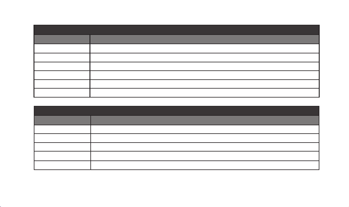
G10 Receiver Information
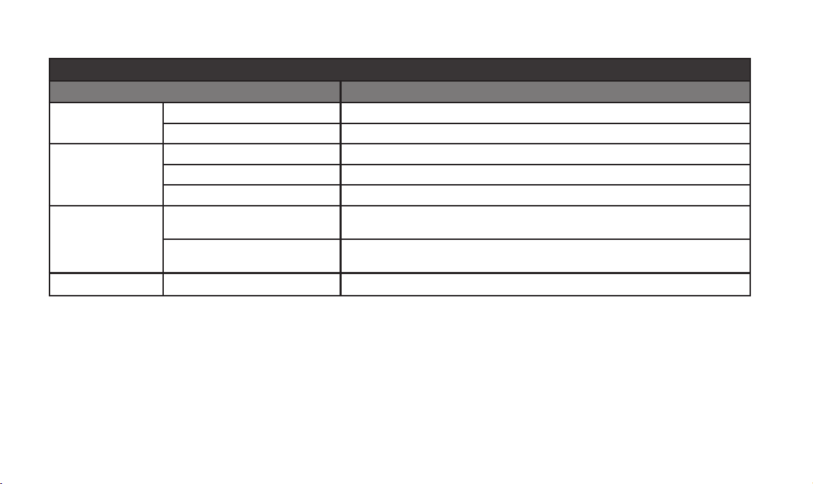
G10 Receiver (G10T or G10TII transmitter docked)
LED State Condition
White (solid) G10T or G10TII charging or fully charged
White(icker) System has auto-scanned and is changing its channel
Red(ash) G10T or G10TII not docked properly—Try un-docking and re-docking
Pink (pulse) Connected to Mac or PC, Line 6 Updater open
Pink (solid) ConnectedtoMacorPC,rmwareupdateinprogress
O No power to receiver
G10 Receiver (G10T or G10TII transmitter un-docked)
LED State Condition
White (solid) Transmission received, more than 30 minutes of runtime
Red(slowash) Transmission received, less than 30 minutes of runtime
White (pulse) Receiver on, but no transmission received
White(icker) Transmission dropout (RF mute)
O No power to receiver
10
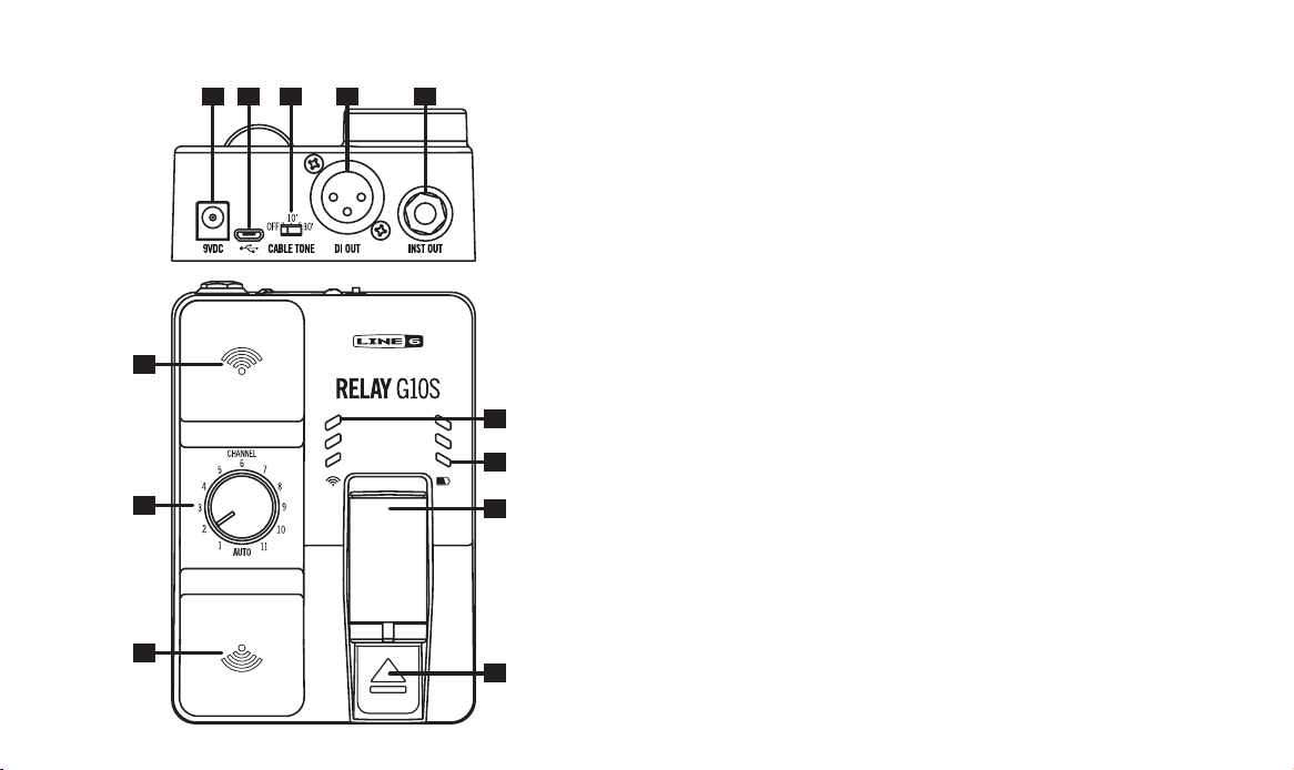
Relay G10S Receiver Details
7
7
3
6
8
9
11
10
1 5 42
1. Cable Tone - When an instrument is connected to a pedal or
amp with a cable, the cable alters the sound, depending
on the cable’s length. Cable Tone adds a 10 feet or 30 feet
cable emulation to the sound.
2. Micro USB - Useforrmwareupdatesoroptionalpower.
3. 9V DC Power - Use for primary DC (9V DC / 500mA) power.
The provided AC adapter serves as the disconnect device.
4. Instrument Output - Connect to the input of a guitar pedal
oramplier.
5. XLR DI Output - Balanced XLR output for connection to a
mixing desk, audio interface, powered speaker, or similar
with DI level.
6. Channel Selector - With the G10T or G10TII transmitter
docked in the receiver, set to AUTO for automatic channel
selection. Or, with the transmitter docked in the receiver,
settoa channelnumberto select axedchannel. This
is recommended when several wireless units are in use.
7. Antennas - Diversity antennas receive the RF signal from
the transmitter. Please make sure that the antennas are
not covered.
8. RF LEDs - 3 LEDs indicate the RF signal quality.*
9. Battery LEDs - 3 LEDs indicate the amount of battery life
while the G10T or G10TII is docked or in use.*
11
*NOTE: Please see “G10S Receiver Information” on page
12 for details regarding the system’s LED states.
10. Release Latch - Keeps the G10T or G10TII in a secure
transport position. To remove the transmitter, push down
on the latch while pulling the transmitter out.
11. G10T or G10TII Transmitter, Docked - With the G10T or G10TII
transmitter docked, the battery is charged and the channel
is set on the transmitter.
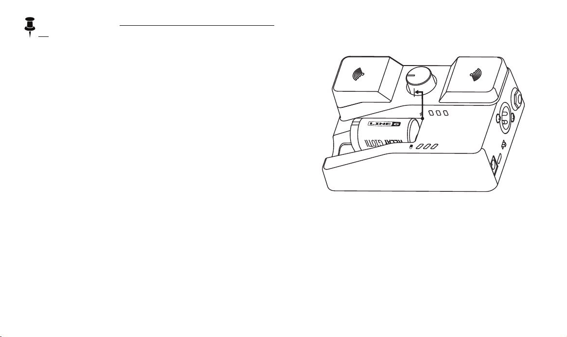
With the Channel Selector set to AUTO, the G10S receiver
performs a scan and automatically sets the receiver and
transmitter to the best available channel.
To store and transport the Relay G10S system - Pull the
G10T or G10TII transmitter out to the rst click so that it is
poweredoandthebatterycannotdischarge.
12
G10S Receiver Information
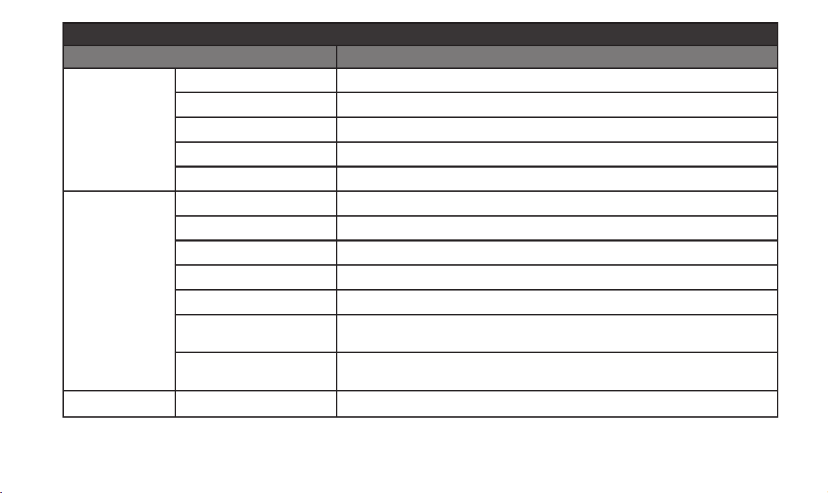
G10S Receiver (G10T or G10TII transmitter docked)
LED State Condition
Battery LEDs
Green (cycle 1-2-3) G10T or G10TII charging
3 Green LEDs (solid) G10T or G10TII fully charged
RF LEDs
3 Red LEDs (solid) More than 75% interference (not usable)
2 Red LEDs (solid) 50% interference (usable, but only for short range)
1 Red LED (solid) 25% interference (usable, also indicates G10S power on)
BatteryLEDsO
RF LEDs On
BatteryLEDs—O
RF LEDs—Red (cycle 3-2-1)
G10T or G10TII not docked properly—Try un-docking and re-docking.
BatteryLEDs—O
RF LEDs—3 Red LEDs (solid)
Connected to Mac or PC, Line 6 Updater application open
AllLEDsO No power to receiver
13
G10S Receiver (G10T or G10TII transmitter un-docked)
LED State Condition
Battery LEDs
3 Green LEDs (solid) Transmission received, more than 4.5 hours of runtime
2 Green LEDs (solid) Transmission received, more than 3 hours of runtime
1 Green LED (solid) Transmission received, more than 1.5 hours of runtime
1 Red LED (solid) Transmission received, more than 30 minutes of runtime
1RedLED(ash) Transmission received, less than 30 minutes of runtime
RF LEDs
3 Green LEDs (solid) Transmission received, good signal strength
2 Green LEDs (solid) Transmission received, average signal strength
1 Green LED (solid) Transmission received, poor signal strength
3 Red LEDs (solid) No transmission received, more than 75% interference (not usable)
2 Red LEDs (solid) No transmission received, 50% interference (usable, but only for short range)
1 Red LED (solid)
No transmission received, 25% interference (usable, also indicates G10S power
on)
Red (cycle 3-2-1)
G10S channel knob has been changed from its setting since G10T or G10TII was
last docked
AllLEDsO No power to receiver

14
Serial No.: _____________________________