

Milestone Systems
XProtect
®
Professional VMS 2016 R3
Administrator Manual
XProtect
®
Professional
XProtect
®
Express
XProtect
®
Essential

XProtect Professional VMS 2016 R3 - Administrator Manual
Contents
2
Contents
Before you start ....................................................... 11
About this manual ............................................................... 11
Product comparison chart.................................................... 11
About minimum system requirements ................................. 13
About naming of host names ............................................... 13
About important port numbers ............................................ 13
About daylight saving time .................................................. 14
About time servers .............................................................. 15
About virus scanning ........................................................... 15
System overview ...................................................... 17
Software and system components ....................................... 17
Clients ................................................................................. 18
XProtect Smart Client ......................................................................... 19
Milestone Mobile client ....................................................................... 19
XProtect Web Client ............................................................................ 21
Recording Server Manager .................................................. 22
XProtect Download Manager ............................................... 23
Licenses............................................................................... 25
About licenses .................................................................................... 25
License information overview ............................................................. 26
About automatic license activation ..................................................... 28
About device changes without activation ........................................... 28
Hardware device summary ................................................................. 30

XProtect Professional VMS 2016 R3 - Administrator Manual
Contents
3
About replacing hardware devices ...................................................... 30
Get additional licenses ........................................................................ 31
About license activation ..................................................................... 31
Install and upgrade .................................................. 33
Install your system software ............................................... 33
Install XProtect Smart Client ............................................... 33
Install video device drivers ................................................. 35
Upgrade ............................................................................... 35
About upgrading ................................................................................. 35
About updates .................................................................................... 36
Upgrading from one product version to another product version........ 36
Upgrading from a current version of your product to a different current
XProtect Professional VMS product ..................................................... 37
About removing system components ................................... 38
First time use ........................................................... 39
Configure the system in the Management Application ......... 39
Best practices ...................................................................... 41
About protecting recording databases from corruption ...................... 41
About saving changes to the configuration ......................................... 42
About using the help ........................................................................... 42
About restarting services .................................................................... 43
Monitor storage space usage .............................................................. 43
View video from cameras in Management Application ........................ 44
Getting started ......................................................... 45
About the Getting started page ........................................... 45
Automatic configuration wizard ........................................... 45
Automatic configuration wizard: First page ........................................ 45

XProtect Professional VMS 2016 R3 - Administrator Manual
Contents
4
Automatic configuration wizard: Scanning options ............................. 45
Automatic configuration wizard: Select hardware manufacturers to scan
for ...................................................................................................... 45
Automatic configuration wizard: Scanning for hardware devices ....... 46
Automatic configuration wizard: Continue after scan ......................... 46
Add hardware wizard .......................................................... 46
Express ............................................................................................... 47
Manual ................................................................................................ 48
Configure storage wizard .................................................... 50
Configure storage: Video settings and preview .................................. 50
Configure storage: Online schedule .................................................... 51
Configure storage: Live and recording settings (motion JPEG cameras)52
Configure storage: Live and recording settings - H.264/MPEG4 cameras53
Configure storage: Drive selection ...................................................... 55
Configure storage: Recording and archiving settings .......................... 57
Adjust motion detection wizard ........................................... 58
Adjust motion detection: Exclude regions ........................................... 58
Adjust motion detection: Motion detection ......................................... 59
Manage user access wizard ................................................. 60
Manage user access: Basic and Windows users .................................. 60
Manage user access: Access summary ................................................ 61
Advanced configuration ........................................... 62
Hardware devices ................................................................ 62
About hardware devices ..................................................................... 62
About microphones ............................................................................. 62
About speakers ................................................................................... 62
About recording audio ........................................................................ 62
About dedicated input/output devices ................................................ 63
Show or hide microphones or speakers .............................................. 63

XProtect Professional VMS 2016 R3 - Administrator Manual
Contents
5
Configure hardware devices ............................................................... 63
Delete/disable hardware devices ....................................................... 64
About replacing hardware devices ...................................................... 64
About the Replace Hardware Device wizard ....................................... 65
Speaker properties ............................................................................. 66
Hardware properties ........................................................................... 67
Cameras and storage information........................................ 69
About video and recording configuration ............................................ 69
About database resizing ..................................................................... 69
About motion detection ...................................................................... 69
About motion detection and PTZ cameras ........................................... 71
Configure camera-specific schedules .................................................. 71
Configure when cameras should do what ........................................... 73
Configure motion detection ................................................................ 73
Disable or delete cameras .................................................................. 73
Move PTZ type 1 and 3 to required positions ...................................... 74
Recording and storage properties ....................................................... 75
Camera properties .............................................................................. 89
MJPEG video format ............................................................................ 90
MPEG video format ............................................................................. 92
Microphones ...................................................................... 106
About microphones ........................................................................... 106
Configure microphones or speakers.................................................. 106
Show or hide microphones or speakers ............................................ 106
Microphone (properties) ................................................................... 106
Events and output ............................................................. 107
About input and output ..................................................................... 107
About events and output .................................................................. 107
Overview of events and output ......................................................... 108

XProtect Professional VMS 2016 R3 - Administrator Manual
Contents
6
Add an analytics event ...................................................................... 110
Add a hardware input event ............................................................. 110
Add a hardware output ..................................................................... 110
Add a manual event .......................................................................... 111
Add a generic event .......................................................................... 112
Add a timer event ............................................................................. 112
Configure hardware output on event ................................................ 112
Configure general event handling ..................................................... 113
Generate alarms based on analytics events ...................................... 113
Test a generic event ......................................................................... 114
General event properties .................................................................. 115
Events and output properties ........................................................... 116
Scheduling and archiving .................................................. 124
About scheduling .............................................................................. 124
About archiving ................................................................................ 124
Configure general scheduling and archiving ..................................... 129
General scheduling properties .......................................................... 130
Camera-specific scheduling properties ............................................. 133
Matrix ................................................................................ 134
About Matrix video-sharing .............................................................. 134
About Matrix-recipients .................................................................... 135
Configure Matrix ............................................................................... 135
Matrix properties .............................................................................. 135
Logs ................................................................................... 137
About logs ........................................................................................ 137
Configure system, event and audit logging ....................................... 140
Log properties .................................................................................. 140
Notifications ...................................................................... 141
About notifications ........................................................................... 141

XProtect Professional VMS 2016 R3 - Administrator Manual
Contents
7
Email ................................................................................................ 142
SMS .................................................................................................. 144
Scheduling ........................................................................................ 146
Central ............................................................................... 147
About Central ................................................................................... 147
Enable XProtect Central .................................................................... 147
Central properties ............................................................................. 147
Access control ................................................................... 148
About access control integration ...................................................... 148
XProtect Access licenses ................................................................... 148
Wizard for access control system integration ................................... 149
Access control properties ................................................................. 150
Server access .................................................................... 155
About server access .......................................................................... 155
About registered services ................................................................. 155
Configure server access .................................................................... 156
Server access properties .................................................................. 156
Master/Slave ..................................................................... 158
About master and slave .................................................................... 158
Configure master and slave servers .................................................. 158
Master/slave properties ................................................................... 159
Users ................................................................................. 160
About users ...................................................................................... 160
Add basic users ................................................................................ 160
Add Windows users .......................................................................... 160
Add user groups ............................................................................... 161
Configure user and group rights ....................................................... 161
User properties ................................................................................. 162

XProtect Professional VMS 2016 R3 - Administrator Manual
Contents
8
Services ............................................................................. 166
About services .................................................................................. 166
About the tray icons ......................................................................... 167
Start and stop services ..................................................................... 168
Start, stop, or restart the Event Server service ................................. 169
View Event Server or MIP logs .......................................................... 170
Servers .............................................................................. 171
LPR servers ...................................................................................... 171
Milestone Mobile ............................................................................... 206
Milestone ONVIF Bridge .................................................................... 227
Alarms ............................................................................... 237
About alarms .................................................................................... 237
About maps ...................................................................................... 239
Add an alarm .................................................................................... 239
Add a time profile (for alarms) ......................................................... 239
Alarms properties ............................................................................. 240
MIP plug-ins ...................................................................... 244
About MIP plug-ins ........................................................................... 244
XProtect Transact .............................................................. 244
XProtect Transact introduction ......................................................... 244
XProtect Transact configuration ....................................................... 248
Options .................................................................. 257
About automatic device discovery ..................................... 257
Change default file paths ................................................... 257
About Customer Dashboard ............................................... 257
Settings ............................................................................. 258
General ............................................................................................. 258

XProtect Professional VMS 2016 R3 - Administrator Manual
Contents
9
User Interface .................................................................................. 259
Connecting Hardware Devices .......................................................... 260
Default File Paths ............................................................................. 261
Access Control Settings .................................................................... 262
Audio Recording ............................................................................... 262
Analytics Events (properties) ........................................................... 263
Event Server Settings ....................................................................... 263
System maintenance .............................................. 265
Backing up and restoring configuration ............................. 265
About backup and restore of configuration ....................................... 265
Back up system configuration ........................................................... 265
Restore system configuration ........................................................... 265
Back up and restore alarm and map configuration ........................... 266
Export and import Management Application configuration ............... 269
Restore system configuration from a restore point ........................... 270
Importing changes to configuration .................................. 271
About importing changes to configuration ........................................ 271
About required fields for CSV files when you import changes to
configurations .................................................................................. 271
Import changes to configuration ...................................................... 272
Glossary of Terms .................................................. 273
Index ..................................................................... 281

XProtect Professional VMS 2016 R3 - Administrator Manual
Copyright, trademarks and disclaimer
10
Copyright, trademarks and disclaimer
Copyright 2016 Milestone Systems A/S
Trademarks
XProtect is a registered trademark of Milestone Systems A/S.
Microsoft and Windows are registered trademarks of Microsoft Corporation. App Store is a service
mark of Apple Inc. Android is a trademark of Google Inc.
All other trademarks mentioned in this document are trademarks of their respective owners.
Disclaimer
This text is intended for general information purposes only, and due care has been taken in its
preparation.
Any risk arising from the use of this information rests with the recipient, and nothing herein should
be construed as constituting any kind of warranty.
Milestone Systems A/S reserve the right to make adjustments without prior notification.
All names of people and organizations used in the examples in this text are fictitious. Any
resemblance to any actual organization or person, living or dead, is purely coincidental and
unintended.
This product may make use of third party software for which specific terms and conditions may
apply. When that is the case, you can find more information in the file
3rd_party_software_terms_and_conditions.txt located in your Milestone system installation
folder.

XProtect Professional VMS 2016 R3 - Administrator Manual
Before you start
11
Before you start
About this manual
This covers all four products in the XProtect Professional VMS suite:
XProtect® Professional
XProtect® Express
XProtect® Essential
The manual describes all settings and functionality available to you when you use the most feature-
rich XProtect Professional VMS product, XProtect Enterprise.
If you are using one of the other XProtect Professional VMS products, you may have less
functionality available to you. Topics may mention functionality or settings that are only available
in a more advanced version of the XProtect Professional VMS products. In such cases, notes in the
top of the relevant topic indicate that you may not have this functionality available to you.
For more information about available functionality in your system, see the product comparison
chart (on page 11).
From the 2016 R3 release, the XProtect Go product is discontinued and XProtect Essential can be
downloaded and installed for free. Among other things, it means that:
- The maximum number of cameras changes from 26 to 48, 8 are for free.
- XProtect Essential systems can no longer be interconnected to XProtect Corporate systems.
- XProtect Smart Client 2016 R2 and earlier versions cannot connect to XProtect Essential 2016 R3
systems or newer.
For more information about changes to XProtect Essential, visit our website
https://www.milestonesys.com/our-products/video-management-software/xprotect-essential/.
Product comparison chart
XProtect Professional VMS is available in four different versions:
XProtect Professional
XProtect Express
XProtect Essential
The complete product comparison chart is available on the product overview page on the Milestone
website http://www.milestonesys.com/our-products/xprotect-software-suite.
Below is a list of the main differences between the products:
Name
XProtect
Essential
XProtect
Express
XProtect
Professional
XProtect
Enterprise
Type of deployment
Single-server
Single-server
Multi-server
Multi-server

XProtect Professional VMS 2016 R3 - Administrator Manual
Before you start
12
Name
XProtect
Essential
XProtect
Express
XProtect
Professional
XProtect
Enterprise
Maximum number of
connected cameras per
system
48,
8 for free
48
Unlimited
Unlimited
Maximum number of
supported recording
servers
1
1
Unlimited
Unlimited
Maximum number of
viewing client users
5
5
Unlimited
Unlimited
Microsoft Active Directory
support
-
-
✓
✓
Alarm Manager
Not fully
Not fully
✓
✓
Map function
Single-layer
only
Single-layer
only
✓
✓
Archiving to network
storage
-
✓
✓
✓
Third-party application
integration with MIP SDK
-
✓
✓
✓
Milestone Interconnect™
-
Remote site
Remote site
Remote site
Customer Dashboard
✓
(requires a
subscription
package)
✓
✓
✓
Remote connect services
✓
(requires a
subscription
package)
✓
✓
✓
Browse DVR recordings
-
-
-
✓
Audio support
One-way
One-way
Two-way
Two-way
Preset patrolling
-
✓
✓
✓
Combine patrolling and
go-to preset on event
-
-
✓
✓
Generic events from
external systems
-
✓
✓
✓
Event-based matrix
control
-
-
✓
✓
Supports XProtect Access
-
✓
✓
✓
Supports XProtect LPR
-
✓
✓
✓

XProtect Professional VMS 2016 R3 - Administrator Manual
Before you start
13
Name
XProtect
Essential
XProtect
Express
XProtect
Professional
XProtect
Enterprise
Supports XProtect
Transact
-
✓
✓
✓
Supports Milestone ONVIF
Bridge
-
✓
✓
✓
Supports XProtect Retail
-
✓
✓
✓
About minimum system requirements
Important: Your system no longer supports Microsoft
®
Windows
®
2003, but you can still
run/access clients from computers with Windows 2003.
Important: Your system no longer supports Microsoft
®
Windows
®
32-bit OS, but you can still
run/access XProtect Web Client and XProtect Smart Client from computers with Windows 32-bit
OS.
For information about the minimum system requirements to the various components of your
system, go to the Milestone website http://www.milestonesys.com/SystemRequirements.
About naming of host names
Names of hosts you use in connection with your VMS system must follow the Microsoft standard of
naming. This means that all host names must only use the ASCII letters 'a' through 'z' (in a case-
insensitive manner), the digits '0' through '9', and the hyphen ('-'). If you use country- or
regionally-specific characters as part of a host name for a component you use with the VMS, you
may not be able to establish a connection between the system and the host machine.
You must have administrator rights on the computer that should run the surveillance system. If
you do not have administrator rights, you cannot configure the surveillance system.
About important port numbers
Your system uses specific ports when it communicates with computers, cameras and other devices.
To be sure that your system runs as smoothly as possible, make sure that the following ports are
open for data traffic on your network when you use your system:
Name
Description
Port 20 and 21 (inbound
and outbound)
Used for FTP traffic.
File Transfer Protocol (FTP) is a standard for exchanging files
across networks. FTP uses the TCP/IP standards for data transfer,
and is often used for uploading or downloading files to and from
servers.

XProtect Professional VMS 2016 R3 - Administrator Manual
Before you start
14
Name
Description
Port 25 (inbound and
outbound)
Used for SMTP traffic.
Simple Mail Transfer Protocol (SMTP) is a standard for sending e-
mail messages between servers. This port should be open
because some cameras may send images to the surveillance
system server via e-mail.
Port 80 (inbound and
outbound)
Used for HTTP traffic between the surveillance server, cameras,
and XProtect Smart Client.
It is the default communication port for the surveillance system's
Image Server service.
Port 554 (inbound and
outbound)
Used for RSTP traffic in connection with H.264 video streaming.
Port 1024 (outbound only)
Used for HTTP traffic between cameras and the surveillance
server.
Port 1234 (inbound and
outbound)
Used for event handling.
Port 1237 (inbound and
outbound)
Used for communication with XProtect Central.
Port 8081 and 8082
Used for communication with the Mobile service.
Port 22331
Used for communication with the Event Server service.
You or your organization may also use other port numbers. An example could be that you have
changed the server access (on page 156) port from its default port number (80) to another port
number.
About daylight saving time
Daylight saving time (DST) is the practice of advancing clocks in order for evenings to have more
daylight and mornings to have less. The use of DST varies between countries/regions.
When you work with a surveillance system, which is inherently time-sensitive, it is important that
you know how the system handles DST.
Spring: Switch from Standard Time to DST
The change from standard time to DST is not much of an issue since you jump one hour forward.
Example:
The clock jumps forward from 02:00 standard time to 03:00 DST, and the day has 23 hours. In
that case, there is no data between 02:00 and 03:00 in the morning since that hour, for that day,
did not exist.
Fall: Switch from DST to Standard Time
When you switch from DST to standard time in the fall, you jump one hour back.
Example:

XProtect Professional VMS 2016 R3 - Administrator Manual
Before you start
15
The clock jumps backward from 02:00 DST to 01:00 standard time, repeating that hour, and the
day has 25 hours. You reach 01:59:59, then immediately revert back to 01:00:00. If the system
did not react, it would essentially re-record that hour, so the first instance of 01:30 would be
overwritten by the second instance of 01:30.
To solve such an issue from happening, your system archives the current video in the event the
system time changes by more than five minutes. You cannot view the first instance of the 01:00
hour directly in any clients, but the data is recorded and safe. You can browse this video in
XProtect Smart Client by opening the archived database directly.
About time servers
When your system receives images from cameras, these images are instantly time-stamped. Since
hardware devices are separate units which may have separate timing devices, the hardware device
time and your system time may not be fully synchronized. The result is that your system may stop
recording from the hardware devices all together if there is a discrepancy between hardware device
time and your system time.
To prevent this from happening, use a time server to auto-synchronize camera and system time.
This allows you to have consistent time-synchronization. Not all cameras support timestamps, so
make sure your camera supports this before you begin to use a time server.
You can use the recording server as a time server if you want to (see "Connecting Hardware
Devices" on page 260).
About virus scanning
As is the case with any other database software, if an antivirus program is installed on a computer
running XProtect® software, it is important that you exclude specific file types and locations, as
well as certain network traffic. Without implementing these exceptions, virus scanning uses a
considerable amount of system resources. On top of that, the scanning process can temporarily
lock files which likely results in a disruption in the recording process or even database corruption.
When you need to perform virus scanning, do not scan Recording Server directories containing
recording databases. The recording server directories are set to c:\mediadatabase\ by default, as
well as all folders under that location.
Avoid also to perform virus scanning on archive storage directories. In older versions of the
software, the databases are by default located in the installation folder, each being a subfolder with
the MAC address of the device recorded.
Create the following additional exclusions:
File types: .blk, .idx, .pic, .pqz, .sts, .ts
C:\Program Files\Milestone or C:\Program Files (x86)\Milestone and all subdirectories.
Exclude network scanning on TCP ports:
Product
TCP ports
XProtect Professional VMS
products
80, 25, 21, 1234, 1237, 22331
Milestone Mobile
8081

XProtect Professional VMS 2016 R3 - Administrator Manual
Before you start
16
or
Exclude network scanning of the following processes:
Product
Processes
XProtect Professional VMS
products
RecordingServer.exe, ImageServer.exe,
ManagementApplication.exe, ImageImportService.exe,
RecordingServerManager.exe,
VideoOS.ServiceControl.Service.exe, VideoOS.Event.Server.exe
Milestone Mobile
VideoOS.MobileServer.Service.exe
Organizations may have strict guidelines regarding virus scanning, however it is important that the
above locations and files are excluded from virus scanning.

XProtect Professional VMS 2016 R3 - Administrator Manual
System overview
17
System overview
Software and system components
Your system consists of a number of components, each targeted at specific tasks and user types.
Software components
Management Application
The Management Application is the main application in which you
add cameras, set up users and configure your system.
You do not use the Management Application to view live, playback
or archived video. Instead, you use one of the viewing clients.
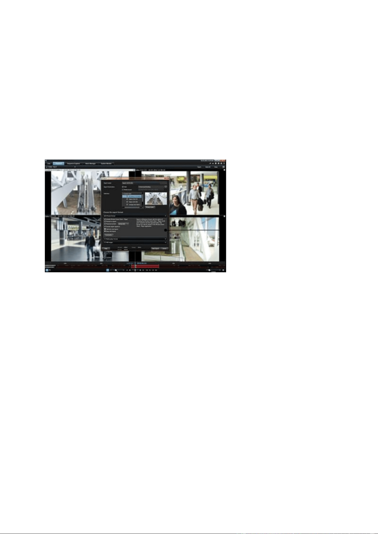
XProtect® Smart Client
XProtect Smart Client is a client for the daily operations of
security installations. Its streamlined interface makes it easy to
monitor installations of all sizes, manage security incidents and
access and export live and recorded video.
You must install XProtect Smart Client on any computer that
should be able to connect to your system and view video.
Milestone recommends that you always use the latest version of
XProtect Smart Client to best use new features and functions
included in your surveillance system.
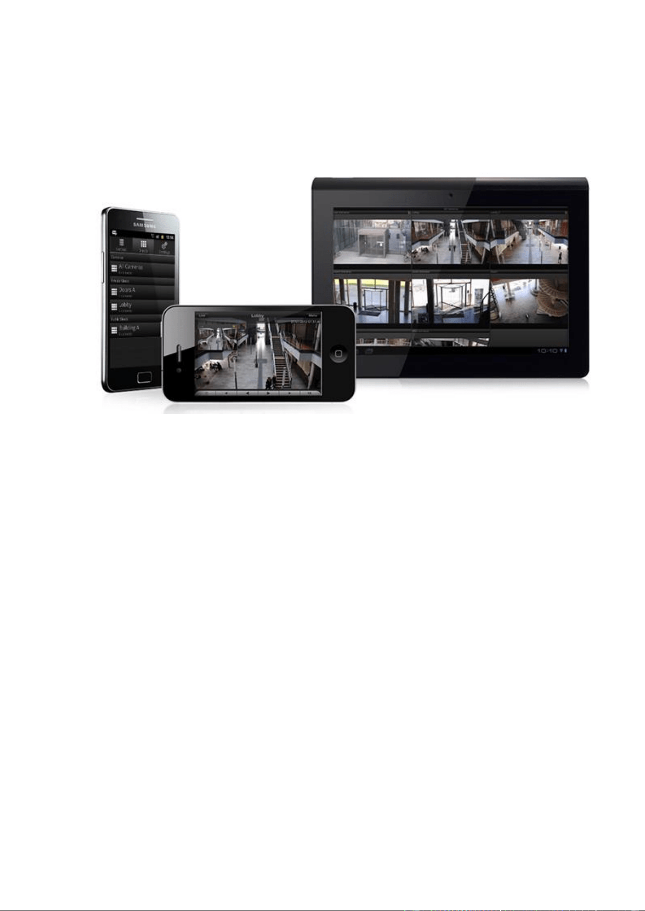
Milestone Mobile
A free application designed by Milestone that allows you to view
video from your system from almost anywhere on your
smartphone or tablet.
You must install Milestone Mobile on all devices that should be
able to connect to your system and view video.
You can also control outputs, such as opening and closing doors
and switching lights on or off, allowing you to gain control and
dynamically respond to incidents in the system.
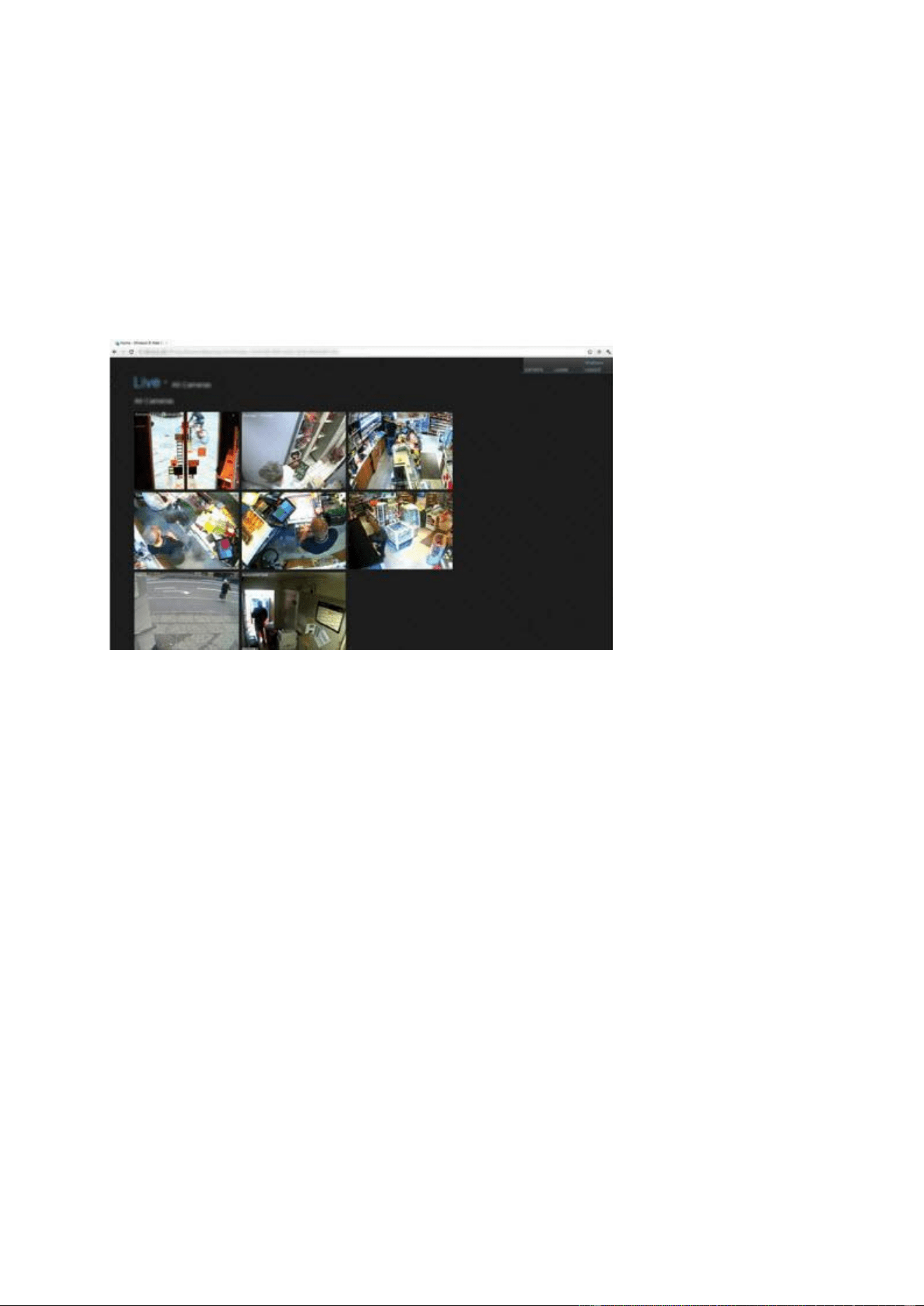
XProtect® Web Client
A simplified web-based client application for XProtect surveillance
systems for viewing, playing back and sharing video from most
operating systems and web browsers.
You do not need to install any software to access XProtect Web
Client. To access your system through XProtect Web Client, you
must know the address of the surveillance system's server.
System components
Recording Server service
The Recording Server service runs to ensure that devices transfer
video streams to your system. The Recording Server service is
installed automatically and runs in the background on the
surveillance system server.
You manage the service through the Management Application.

XProtect Professional VMS 2016 R3 - Administrator Manual
System overview
18
Event Server service
Handles configuration of alarms and maps from all servers within
the surveillance system installations, including Master/slave
setups, throughout your organization.
The Event Server service enables monitoring and instant
overview of alarms and possible technical problems within your
systems.
The event server is automatically installed on the surveillance
system server and runs in the background.
Microsoft
®
SQL Server
Express Database
The surveillance system's alarm data is stored in a SQL Server
Express database.
The SQL database is a lightweight, yet powerful, version of a full
SQL server which is automatically installed on, and runs in the
background of, your surveillance system server.
Image Server service
Handles access to the surveillance system for users logging in
with clients.
The Image Server service is automatically installed and runs in
the background on the surveillance system server. You can
manage the service through the Management Application.
Download Manager
Manages the system-related features your organization's users
can access from a targeted welcome page on the surveillance
system server.
Clients
Clients are applications used for viewing live and recorded video from the hardware devices set up
in the Management Application. Your system supports three different clients:
XProtect Smart Client
Milestone Mobile client
XProtect Web Client
XProtect Professional VMS 2016 R3 - Administrator Manual
System overview
19
XProtect Smart Client
About XProtect Smart Client
Designed for Milestone XProtect®
IP video management software, the XProtect Smart Client is an
easy-to-use client application that provides intuitive control over security installations. Manage
security installations with XProtect Smart Client which gives users access to live and recorded
video, instant control of cameras and connected security devices, and an overview of recordings.
Available in multiple local languages, XProtect Smart Client has an adaptable user interface that
can be optimized for individual operators’ tasks and adjusted according to specific skills and
authority levels.
The interface allows you to tailor your viewing experience to specific working environments by
selecting a light or dark theme, depending on room lighting or brightness of the video. It also
features work-optimized tabs and an integrated video timeline for easy surveillance operation.
Using the MIP SDK, users can integrate various types of security and business systems and video
analytics applications, which you manage through XProtect Smart Client.
XProtect Smart Client must be installed on users' computers. Surveillance system administrators
manage clients' access to the surveillance system through the Management Application. Recordings
viewed by clients are provided by your XProtect system's Image Server service. The service runs in
the background on the surveillance system server. Separate hardware is not required.
To download XProtect Smart Client, you must connect to the surveillance system server which
presents you with a welcome page that lists available clients and language versions. System
administrators can use XProtect Download Manager to control what clients and language versions
should be available to users on the welcome page of the XProtect Download Manager.
Milestone Mobile client
About Milestone Mobile client
Milestone Mobile client is a mobile surveillance solution closely integrated with the rest of your
XProtect system. It runs on your Android tablet or smartphone, your Apple
®
tablet, smartphone or
portable music player or your Windows Phone 8 tablet or smartphone and gives you access to
cameras, views and other functionality set up in the management clients.
XProtect Professional VMS 2016 R3 - Administrator Manual
System overview
20
Use the Milestone Mobile client to view and play back live and recorded video from one or multiple
cameras, control pan-tilt-zoom (PTZ) cameras, trigger output and events and use the Video push
functionality to send video from your device to your XProtect system.
If you want to use Milestone Mobile client with your system, you must add a Mobile server to
establish the connection between the Milestone Mobile client and your system. Once the Mobile
server is set up, download the Milestone Mobile client for free from Google Play, App Store or
Windows Phone Store to start using Milestone Mobile.
You need one hardware device license per device that should be able to push video to your
XProtect system.
XProtect Professional VMS 2016 R3 - Administrator Manual
System overview
21
XProtect Web Client
About XProtect Web Client
XProtect Web Client is a web-based client application for viewing, playing back and sharing video.
It provides instant access to the most commonly used surveillance functions, such as viewing live
video, play back recorded video, print and export evidence. Access to features depends on
individual user rights which are set up in the management client.
To enable access to the XProtect Web Client, you must install a Mobile server to establish the
connection between the XProtect Web Client and your system. The XProtect Web Client itself does
not require any installation itself and works with most Internet browsers. Once you have set up the
Mobile server, you can monitor your XProtect system anywhere from any computer or tablet with
Internet access (provided you know the right external/Internet address, user name and password).
Access XProtect Web Client
If you have a Milestone Mobile server installed on your computer, you can use the XProtect
Web
Client to access your cameras and views. Because you do not need to install XProtect Web Client,
you can access it from the computer where you installed the Milestone Mobile server, or any other
computer you want to use for this purpose.
1. Set up the Milestone Mobile server in the Management Application.
2. If you are using the computer where Milestone Mobile server is installed, you can right-click
the Milestone Mobile Server icon in the system tray, and select Open XProtect Web
Client.
3. If you are not using the computer where Milestone Mobile server is installed, you can access
it from a browser. Continue with step 4 in this process.
4. Open an Internet browser (Internet Explorer, Mozilla Firefox, Google Chrome or Safari).
5. Type the external IP address, that is, the external address and port of the server on which
the Milestone Mobile server is running.

XProtect Professional VMS 2016 R3 - Administrator Manual
System overview
22
Example: The Milestone Mobile server is installed on a server with the IP address 127.2.3.4
and is configured to accept HTTP connections on port 8081 and HTTPS connections on port
8082 (default settings of the installer).
In the address bar of your browser, type: http://1.2.3.4:8081 or https://1.2.3.4:8082,
depending on whether you want to use a standard HTTP connection or a secure HTTPS
connection. You can now begin using XProtect Web Client.
6. Add the address as a bookmark in your browser for easy future access to XProtect Web
Client. If you use XProtect Web Client on the local computer on which you installed the
Milestone Mobile server, you can also use the desktop shortcut which the installer creates.
Click the shortcut to launch your default browser and open XProtect Web Client.
You must clear the cache of Internet browsers running the XProtect Web Client before you can use
a new version of the XProtect Web Client. System administrators must ask their XProtect Web
Client users to clear their browser cache after upgrading, or force this action remotely (you can do
this action only in Internet Explorer in a domain).
Recording Server Manager
The Recording Server service is a vital part of the surveillance system. Video streams are only
transferred to your system while the Recording Server service is running. The Recording Server
Manager informs you about the state of the Recording Server service. It also lets you manage the
service.
In the notification area (the system tray), the Recording Server Manager's icon indicates whether
the Recording Server service is running or not.
- A green icon in the notification area indicates that the Recording Server service is running.
- A red icon in the notification area indicates that the Recording Server service has stopped.
By right-clicking the icon, you can open the Management Application, start and stop the Recording
Server service, view log files, and view version information.
Monitor System Status
Right-click the notification area's Recording Server icon and select Show System Status to get
access to the Status window.
The Status window lets you view the status of the image server(s) and connected cameras. The
status of each server/camera is indicated by a color:
Green indicates that the server or camera is running correctly.
Gray indicates that the camera (not the server) is not running. Typically, a camera is
indicated in gray in the following situations:
The camera is not online (as defined in the camera's online period schedule).
The Recording Server service has been stopped.
Red indicates that the server or camera is not running. This may because it has been
unplugged or due to a network or hardware error. Errors are listed in the Recording Server
log file.
Place your mouse pointer over a camera in the status window to view details about the relevant
camera. The information appears as a pop-up and updates about every 10 seconds.

XProtect Professional VMS 2016 R3 - Administrator Manual
System overview
23
Resolution
The resolution of the camera.
FPS
The number of frames per second (frame rate) currently used by
the camera. The number updates each time the camera has
received 50 frames.
Frame count
The number of frames received from the camera since the
Recording Server service was last started.
Received KB
The number of kilobytes sent the by camera since the Recording
Server service was last started.
Offline
Indicates the number of times the camera has been offline due to
an error.
XProtect Download Manager
The XProtect Download Manager allows you to manage the system-related features your
organizations can access. You can reach XProtect Download Manager from a targeted welcome
page on the surveillance system server.
To access XProtect Download Manager from Windows' Start menu: Select All Programs >
Milestone XProtect Download Manager > Download Manager.
Examples of user-accessible features
XProtect Smart Client. Users connect to the surveillance server through an Internet
browser where they are presented with a welcome page. From the welcome page, users can
download XProtect Smart Client software and install it on their computers.
Various plug-ins. Downloading such plug-ins can be relevant for users if your organization
uses add-on products with the surveillance system.
The welcome page
The welcome page links to downloads of various features. Users can select language from a menu
in the top right corner of the welcome page.
To view the welcome page, open an Internet browser (for example, Internet Explorer version 6.0
or later) and connect to the following address:
http://[surveillance server IP address or hostname]
If you have configured the Image Server service with a port number other than the default port 80
(you configure this as part of the server access properties), users must specify the port number as
well, separated from the IP address or hostname by a colon:
http://[surveillance server IP address or hostname]:[port number]
The content of the welcome page is managed through XProtect Download Manager and can look
different in different organizations.
Immediately after you install your system, the welcome page provides access to XProtect Smart
Client in all languages. You can also download XProtect Smart Client in 32-bit or 64-bit if you run a
64-bit operating system and in 32-bit if you run a 32-bit operating system. This initial look of the
welcome page is automatically provided through XProtect Download Manager's default
configuration.

XProtect Professional VMS 2016 R3 - Administrator Manual
System overview
24
Default configuration of XProtect Download Manager
XProtect Download Manager has a default configuration. This ensures that your organization's
users can access standard features without the surveillance system administrator having to set up
anything. The XProtect Download Manager configuration is represented in a tree structure.
Download Manager's tree structure explained:
The first level of the tree structure indicates that you are working with a system.
The second level indicates that this is the default setup.
The third level refers to the languages in which the welcome page is available. In the
example, the welcome page is available in a dozen languages (English, Arabic, Danish,
Dutch, French, and more).
The fourth level refers to the features that you can make available to users. For example,
you could limit these features to XProtect Smart Client.
The fifth level ( 5 ) refers to particular versions of each feature, for example, version 4.0,
32-bit, and more that you can make available to users.
The sixth level ( 6 ) refers to the language versions of the features which can be made
available to users. For XProtect Smart Client, which is only available with all languages
embedded, the only option is All Languages.
The fact that only standard features are initially available helps reduce installation time and save
space on the server. There is no need to have a feature or language version available on the server
if nobody is going to use it. You can make more features and/or languages available if you need to.
Making new features available
When you install new features, these are by default selected in XProtect Download Manager and
immediately available to users through the welcome page.
You can always show or hide features on the welcome page by selecting or clearing check boxes in
the tree structure. You can change the sequence in which features and languages are displayed on
the welcome page by dragging items and dropping them in the relevant position.
Hiding and removing features
You can remove features in several ways:
You can hide features from the welcome page by clearing check boxes in XProtect Download
Manager's tree structure. If you do this, the features are still installed on the surveillance system
server, and by selecting check boxes in the tree structure, you can quickly make the features
available again.
You can remove features which have previously been made available through XProtect Download
Manager. This removes the installation of the features on the surveillance system server. The
features disappear from XProtect Download Manager, but installation files for the features are kept
in the surveillance system server's Installers or relevant language folder, so you can re-install
them later if required. To do so:
7. In XProtect Download Manager, click Remove features...
8. In the Remove Features window, select the features you want to remove.
9. Click OK and then click Yes.

XProtect Professional VMS 2016 R3 - Administrator Manual
System overview
25
Licenses
About licenses
If you have installed and registered your XProtect Essential system, you can run the system and
eight hardware device licenses for a year for free. The hardware device licenses are pre-activated
and you can change and replace your hardware devices, as many times you want. They will never
enter a grace period or an expired grace period and they will never appear without licenses.
Only when you upgrade (see "About upgrading to a more a feature-rich XProtect Professional VMS
product" on page 37) to a more advanced VMS product, the rest of this topic and the other
licensing related topics in this documentation is relevant.
When you purchase your software and licenses, you receive:
An order confirmation.
A software license file (SLC) with the .lic extension and named after your SLC (Software
License Code).
Your SLC is also printed on your order confirmation and consists of several numbers and letters
grouped by hyphens similar to this:
Product version 2014 or earlier: xxx-xxxx-xxxx
Product version 2016 or later: xxx-xxx-xxx-xx-xxxxxx
The software license file contains all information about your purchased VMS products and licenses.
Milestone recommends that you store the information about your SLC and a copy of your software
license file in a safe place from which you can find them again. You can also see your SLC from the
Help menu > About.
To get started, you download the software from our website. While you are installing (see "Install
your system software" on page 33) the software, you are asked to provide the software license file.
If you have not yet received the software license file, you can still install the software and run it for
a 30-day trial period with a maximum of eight added cameras and a retention time of maximum
five days. To continue using your system, you must import (see "Importing a new software license
file" on page 37) your software license file before the end of the trial period.
Once the installation is complete and you have activated your licenses, you can see an overview of
your licenses (see "License information overview" on page 26) for the current installation on the
Getting started page. You may need the software license file or your SLC when you, for example
create a My Milestone user account, contact your reseller for support and if you need to make
changes to your system.
You have purchased at least two types of licenses:
Base licenses: As a minimum, you have a base license for one of the XProtect products. Except
for XProtect Essential, you may also have one or more base licenses for XProtect add-on products.
Hardware device licenses: Every hardware device that you add to your XProtect system requires
a hardware device license. You do not need hardware device licenses for speakers, microphones or
input and output devices attached to your cameras. You need only one hardware device license per
video encoder IP address even if you connect several cameras to the video encoder. A video
encoder can have one or more IP addresses.
For more information, see the list of supported hardware on the Milestone website
https://www.milestonesys.com/supported-hardware. If you want to use the video push feature in
Milestone Mobile, you also need one hardware device license per mobile device or tablet that
should be able to push video to your system. If you are short of hardware device licenses, you can
XProtect Professional VMS 2016 R3 - Administrator Manual
System overview
26
disable (see "Disable or delete cameras" on page 73) less important hardware devices to allow new
hardware devices to run instead. You may also need a hardware device license for some devices
that are NOT attached to your cameras. Examples of camera independent devices are perimeter
detectors and some types of audio devices and input/output boxes. See the supported hardware
site https://www.milestonesys.com/supported-hardware on the Milestone website.
Most XProtect add-on products require additional license types. The software license file also
includes information about your licenses for add-on products. Some add-on products have their
own separate software license files. You can find more information about add-on product licenses
here:
XProtect Access (see "XProtect Access licenses" on page 148)
XProtect LPR (see "LPR licenses" on page 173)
XProtect Transact
For add-on product licenses for XProtect Retail and XProtect Screen Recorder, see the
documentation for these products.
For XProtect Express and XProtect Essential
If you install your VMS product on a virtual server, you need to activate your licenses and all
descriptions about license activation, grace periods and other licensing related in this
documentation is applicable for your installation.
However, if you install your VMS product on a physical server, all your purchased licenses are pre-
activated and you can change and replace as many hardware devices you want. You cannot have
licenses in a grace period, in an expired grace period or without licenses because you cannot add
more hardware devices or other licensed devices than you have purchased licenses for. If you buy
more licenses or upgrade your VMS product, you must make a manual activation to get access to
the new licenses or new functionality. For more information, see Get additional licenses (on page
31) or About upgrading (on page 35).
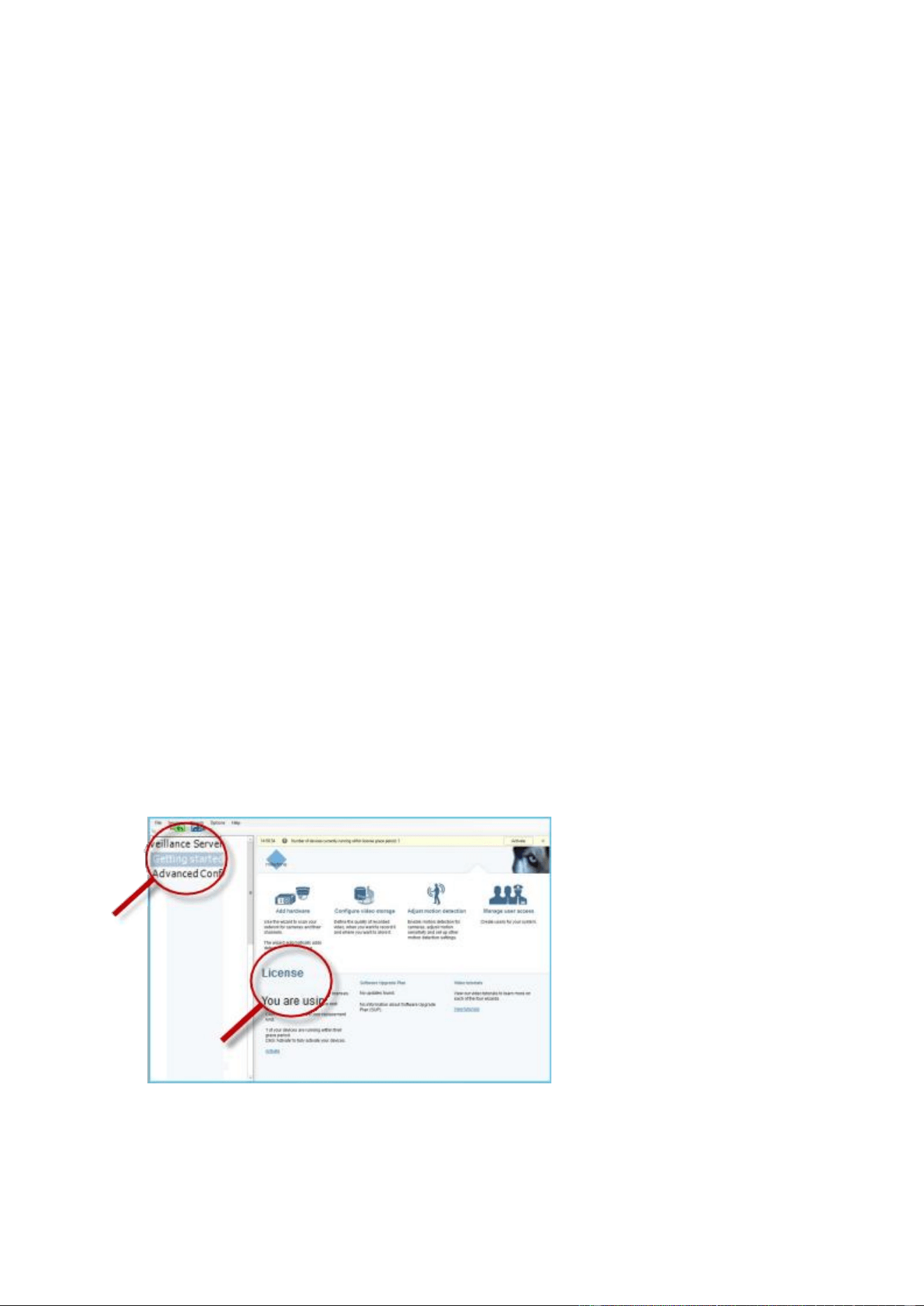
License information overview
On the Getting started page under License in the bottom left corner, see the following
information about your hardware device licenses:
The number of hardware device licenses activated on this server and the total number of
hardware device licenses you have purchased as part of the same software license file.

XProtect Professional VMS 2016 R3 - Administrator Manual
System overview
27
If the same software license file is shared on multiple surveillance systems in a
master/slave setup, the license overview shows the same total number of purchased
licenses for all systems.
Only XProtect Enterprise and XProtect Professional support the master/slave setup feature.
To find out how many free licenses you have, add the number of activated licenses on all
your systems and subtract this number from the total number of purchased licenses.
Alternatively, visit our website for software registration http://online.milestonesys.com.
The maximum number of hardware devices you can add to each server in your VMS
system. To exceed this maximum, you must upgrade to a more advanced XProtect VMS
product. For more information about how to do this, contact your reseller.
The number of activated hardware devices you have replaced or added without having to
activate.
The column Changes without activation shows the number of hardware devices you can
replace or add without having to activate your hardware device licenses as well as how
many changes you have already made since last activation. Hardware devices added within
your number of device changes without activation run as fully activated hardware device
licenses and have the status Licensed in the Hardware device summary (on page 30)
table. Because you can add or replace devices without activating them, you gain flexibility
in the day-to-day maintenance of your system. For more information, see About device
changes without activation (on page 28).
The number of hardware devices running in a 30-day grace period. If you have already
used your number of device changes without activating this or have added more hardware
devices than you have purchased licenses for, the added hardware devices run in a grace
period. Once the grace period expires, cameras are disabled and stops sending video to the
system. You can also see when the first grace period for a hardware device expires.
For easy maintenance and flexibility, your VMS system is set up to automatically activate your
licenses online each time you add or remove hardware devices. Of course, automatic license
activation (see "About automatic license activation" on page 28) requires that your system is
connected to the Internet.
XProtect Professional VMS 2016 R3 - Administrator Manual
System overview
28
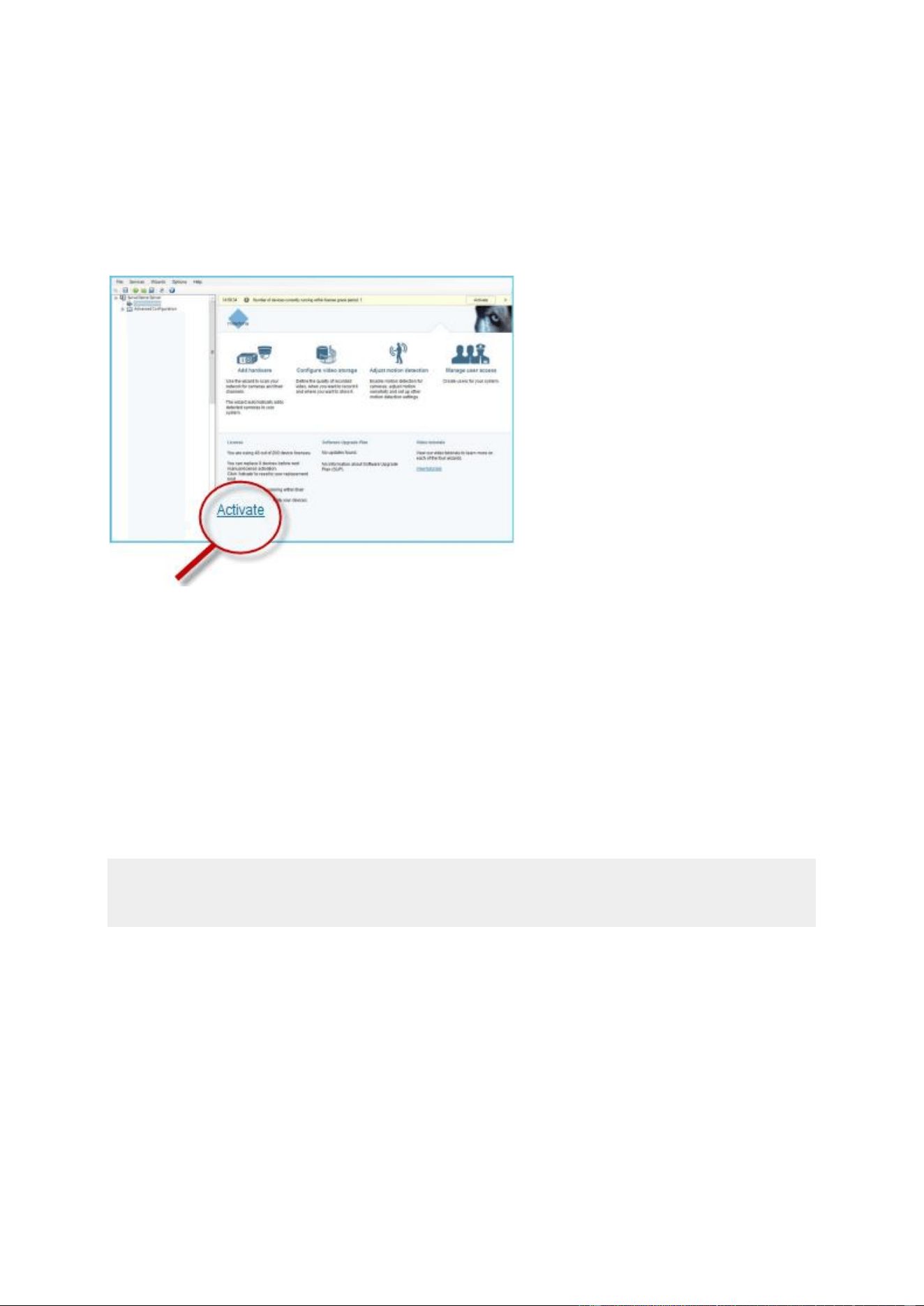
If your system is not connected to the Internet, and you have added or replaced hardware devices
within your number of device changes without activating them or have added hardware devices
that now run in a grace period, click the Activate link to activate your hardware device licenses.
Your number of device changes without activation now reflects the new number of activated
licenses. The hardware devices previously in grace period are moved to activated if you have
enough purchased licenses. For more information, see About license activation (on page 31).
About automatic license activation
Milestone recommends that your surveillance system is online so that your licenses are
automatically activated.
When your system is online, the system activates your hardware devices or other licenses a few
minutes after you have made your changes. The result is that:
you never have to manually start a license activation
the number of used device changes without activation is always zero
no hardware devices are within a grace period, unless you have added more hardware
devices than your number of purchased hardware device licenses allows.
In some cases you must activate licenses manually. Such cases are when you have purchased
additional licenses, if you have bought or renewed a Milestone Care subscription (see "About the
Getting started page" on page 45), or if Milestone has granted you a higher number of device
changes without activation (see "About device changes without activation" on page 28).
About device changes without activation
On the Getting started page, the column Changes without activation shows the number of
hardware devices you can replace or add without having to activate your hardware device licenses
and how many changes you have already made since the last activation.
Hardware devices added within your device changes without activation run as fully activated
hardware device licenses and has the status Licensed in the Hardware device summary (on page
30) table. One year after your last license activation, your number of used device changes
without activation is automatically reset to zero. Once the reset happens, you can continue to
add and replace hardware devices without activating the licenses.

XProtect Professional VMS 2016 R3 - Administrator Manual
System overview
29
The number of device changes without activation differs from installation to installation and is
calculated based on several variables. For a detailed description, see How the number of device
changes without activation is calculated (on page 29).
If your surveillance system is offline for longer periods of time, for example in cases with a
surveillance system on a ship on a long cruise or a surveillance system in a very remote place
without any Internet access, you can contact your Milestone reseller and request a higher number
of device changes without activation.
You must explain why you think you qualify for a higher number of device changes without
activation. Milestone decides each request on an individual basis. Should you be granted a higher
number of device changes without activation, you must activate your licenses to register the higher
number on your XProtect system.
How the number of device changes without activation is
calculated
The device changes without activation are calculated based on three variables. If you have several
installations of the Milestone software, the variables apply to each of them separately. The
variables are:
C% that is a fixed percentage of the total amount of activated licenses.
Cmin that is a fixed minimum value of the number of device changes without
activation.
Cmax that is a fixed maximum value of the number of devices changes without
activation.
The number of device changes without activation can never be lower than the Cmin value or
higher than the Cmax value. The calculated value based on the C% variable changes according to
how many activated devices you have on each installation in your system. Devices added with
device changes without activation are not counted as activated by the C% variable.
Milestone defines the values of all three variables and the values are subject to change without
notification. The values of the variables differ depending on the product.
For more information about the current default values for your product, go to My Milestone
http://www.milestonesys.com/device-change-calculation.
Examples based on C% = 15%, Cmin = 10 and Cmax =100
A customer buys 100 hardware device licenses. He adds 100 cameras to his system. Unless he has
enabled automatic license activation, his device changes without activation is still zero. He
activates his licenses and he now has 15 device changes without activation.
A customer buys 100 hardware device licenses. He adds 100 cameras to his system and activates
his licenses. His device changes without activation is now 15. The customer decides to delete a
hardware device from his system. He has now 99 activated devices and his number of device
changes without activation drops to 14.
A customer buys 1000 hardware device licenses. He adds 1000 cameras and activates his licenses.
His device changes without activation is now 100. According to the C% variable, he should now
have had 150 devices changes without activation, but the Cmax variable only allows him to have
100 devices changes without activation.
A customer buys 10 hardware device licenses. He adds 10 cameras to his system and activates his
licenses. His number of device changes without activation is now 10 because of the Cmin variable.
If the number was only calculated based on the C% variable, he would only have had 1 (15% of
10 = 1.5 rounded off to 1).

XProtect Professional VMS 2016 R3 - Administrator Manual
System overview
30
A customer buys 115 hardware device licenses. He adds 100 cameras to his system and activates
his licenses. His device changes without activation is now 15. He adds another 15 cameras without
activating them, using 15 out of 15 of his device changes without activation. He removes 50 of the
cameras from the system and his device changes without activation goes down to 7. This means
that 8 of the cameras previously added within the 15 device changes without activation go into a
grace period. The customer now adds 50 new cameras. Because the customer activated 100
cameras on his system last time he activated his licenses, the device changes without activation
goes back to 15 and the 8 cameras, which were moved into a grace period, moves back as device
changes without activation. The 50 new cameras go into a grace period.
Hardware device summary
You can get an overview of the status of your hardware device licenses and channels by expanding
Advanced Configuration > Hardware Devices. The Hardware Device Summary table
contains the following information.
Hardware Device Name
The name of your hardware device
License
The licensing status of your hardware devices. You can see the
following statuses: Licensed, [number of] day(s) grace
period, Trial, or Expired.
Video channels
The number of available video channels on your hardware
devices.
Speaker Channels
The number of available speaker channels on your hardware
devices.
Microphone Channels
The number of available microphone channels on your hardware
devices.
Address
The HTTP addresses of your hardware devices.
WWW
Links to your hardware devices' web addresses.
Port
The ports your hardware devices use.
Device Driver
The name of the device drivers associated with your hardware
devices.
About replacing hardware devices
If you remove a hardware device from a recording server and save the configuration, you also free
a hardware device license. Simply disabling a device does not free a license. You can replace a
licensed hardware device with a new hardware device and activate and license it instead. The total
number of purchased hardware device licenses corresponds to the total number of hardware
devices that can run on the surveillance system simultaneously.
When you replace a hardware device, you must use the Replace Hardware Device wizard (see
"About the Replace Hardware Device wizard" on page 65) to map all relevant databases of
cameras, microphones, inputs, outputs, and more. Remember to activate the license when you are
finished.

XProtect Professional VMS 2016 R3 - Administrator Manual
System overview
31
Get additional licenses
If you want to add more hardware devices or other components that require a license that you
currently do not have licenses for, you must buy additional licenses to enable the devices to send
data to your system before the grace period ends.
To get additional licenses for your system, contact your XProtect product reseller.
New licenses to your existing surveillance system version:
Activate your licenses manually to get access to the new licenses.
For more information, see Activate licenses offline (on page 32) or Activate licenses
online (on page 31).
New licenses and an upgraded surveillance system version:
You receive an updated software license file (.lic) with the new licenses and the new
version. You must use the new software license file during the installation of the new
version.
About license activation
This topic is only relevant if your surveillance system is offline or if you want to make a manual
license activation. If your system is online, your licenses are activated automatically. For more
information see About automatic license activation (on page 28).
When you have installed your VMS and added hardware devices, the hardware devices run in a 30-
day grace period. Before the end of the 30-day grace period, you must activate your hardware
device licenses or your hardware devices stop sending video to your surveillance system.
Milestone recommends that you activate your licenses before you make final adjustments to your
system and its hardware devices. For more information, see Activate licenses offline (on page 32)
and Activate licenses online (on page 31).
If you add more hardware devices than the number of purchased hardware device licenses, the
hardware devices run with in a grace period. If you want to see video from these hardware devices
after the expiry of the grace period, you must buy additional licenses (see "Get additional licenses"
on page 31). You can also disable (see "Delete/disable hardware devices" on page 64) less
important cameras to allow new hardware devices to run instead.
If you have several VMS products installed in a master/slave setup, you activate your licenses from
each installation and get an updated and activated .lic file for each installation. This is also the case
if all your VMS products share the same software license file.
Activate licenses online
This topic is only relevant if your surveillance system is offline or if you want to make a manual
license activation. If your system is online, your licenses are activated automatically. For more
information see About automatic license activation (on page 28).
If you have purchased additional licenses or want to upgrade, you must manually activate your
licenses. If the computer that runs the Management Application has Internet access, you can do a
manual online activation.
1. From the File menu, select Activate License Online.
2. The Online License Retrieval dialog box opens and your licenses are activated.

XProtect Professional VMS 2016 R3 - Administrator Manual
System overview
32
Activate licenses offline
This topic is only relevant if your surveillance system is offline or if you want to make a manual
license activation. If your system is online, your licenses are activated automatically. For more
information see About automatic license activation (on page 28).
You must manually activate your licenses if:
You have purchased additional licenses, want to upgrade
You have bought or renewed a Milestone Care subscription (see "About the Getting started
page" on page 45)
Milestone has granted you a higher number of device changes without activation (see
"About device changes without activation" on page 28)
1. From the File menu, select Activate License Offline.
2. Click Export to export a license request file.
3. The license request file is automatically given the same name as your SLC. If you have
several sites, remember to make the name unique so you easily can identify which file
belong to which site.
4. Copy the license request file (.lrq) to a computer with internet access and log into our
website for software registration http://online.milestonesys.com.
5. Copy the activated software license file (.lic) that has the same name as your license
request file to your computer with Management Application.
6. In the same dialog box that you opened in step 1, click Browse to use the activated
software license file.
7. Click Activate.
If the computer that runs the Management Application does not have Internet access, you can
activate licenses offline.
Activate licenses after grace period
If you do not activate a license for a hardware device or other device used with an add-on product
within the grace period, the device becomes unavailable and cannot send data to the surveillance
system.
The device itself, its configuration and other settings are not removed from the system
configuration.
To receive data from the expired device again, activate the license.
For more information see Activate licenses offline (on page 32) and Activate licenses online (on
page 31).

XProtect Professional VMS 2016 R3 - Administrator Manual
Install and upgrade
33
Install and upgrade
Install your system software
Do not install your surveillance software on a mounted drive. A mounted drive is a drive that is
attached to an empty folder on an NTFS (NT File System) volume, with a label or name instead of a
drive letter. If you use mounted drives, critical system features may not work as intended. You do
not, for example, receive any warnings if the system runs out of disk space.
Before you start: shut down any existing surveillance software. If you are upgrading, read
Upgrading from one product version to another product version (on page 36) first.
1. Run the installation file
2. If you have a previous installation of your system or any of the other XProtect Professional
VMS products installed, the system detects this installation and informs you that your
previous installation is removed after installing the new version. If you accept this, click
Yes to continue the installation. All your recordings and configuration from the previous
version are available in the new version
3. Select language for the installer and then click Continue
4. Select Trial to install a 30-day trial version of the system software if you do not have a
software license file named after your SLC. If you have a software license file, first save it
on your local drive. Do not try to import it directly from a network drive or a USB stick.
Import it by typing the destination of the software license file or clicking Browse
5. Read and accept the license agreement. Select the checkbox to enable access to the
Customer Dashboard
6. Select Typical or Custom installation. If you select Custom installation, you can select
application language, which features to install and where to install them. Let the installation
wizard complete
7. If you have installed a trial version, open the Management Application once the installation
is complete and select which of the XProtect Professional VMS products you want to use, for
example XProtect Enterprise.
You can now begin to configure your system (see "Configure the system in the Management
Application" on page 39).
Install XProtect Smart Client
You must install XProtect Smart Client on your computer before you can use it. Download XProtect
Smart Client from the surveillance system server and install it on your computer or install it directly
from a DVD.
Before you begin, visit the Milestone website and verify that your computer meets the XProtect
Smart Client's minimum system requirements http://www.milestonesys.com/SystemRequirements.

XProtect Professional VMS 2016 R3 - Administrator Manual
Install and upgrade
34
Install XProtect Smart Client from the management server
1. Open Internet Explorer and connect to the management server using the URL or IP address
of that server.
2. On the Welcome page, click Language and select the language you want to use.
3. The XProtect Smart Client setup wizard starts. In the wizard, follow the installation
instructions.
The wizard suggests an installation path. Normally, you can use the suggested installation path.
However, if you have previously used add-on products, this path might not be valid anymore.
Install XProtect Smart Client silently
A surveillance system administrator can deploy the system or XProtect Smart Client to users’
computers by using tools such as Microsoft Systems Management Server (SMS). With this tool, you
can build up databases of hardware and software on local networks. You can then use the
databases for distributing and installing software applications over local networks.
To install silently:
1. Locate the XProtect Smart Client .exe file XProtect Smart Client 2016 R3 Installer
x64.exe. Find the file in a subfolder under the folder httpdocs. The httpdocs folder is
located under the folder in which your Milestone surveillance software is installed.
The path is typically (if you are using an English language version of the XProtect Smart
Client):
C:\Program Files (x86)\Milestone\Milestone Surveillance\httpdocs\XProtect
Smart Client Installer\[version number] [bit-version]\All Languages\en-US
For example:
C:\Program Files (x86)\Milestone\Milestone Surveillance\httpdocs\XProtect
Smart Client Installer\2016 (64-bit)\All Languages\en-US
2. Run a silent installation using one of the following two options:
a) Run with default parameter settings:
To run a silent installation using the default values for all parameters, start a command
prompt (cmd.exe) in the directory where the installation program is located and perform
the following command:
XProtect Smart Client:
XProtect Smart Client 2016 R3 Installer x64.exe --quiet
Your system:
Milestone XProtect Professional VMS Products 2016 R3 System Installer.exe --quiet
This performs a quiet installation of XProtect Smart Client or your system using default
values for parameters such as target directory and so on. To change the default settings,
see the following:
b) Customize default parameters using an XML argument file as input:
In order to customize the default installation settings, you must provide an XML file with
modified values as input. In order to generate the XML file with default values, open a
command prompt in the directory where the installation program is located and perform the
following command:

XProtect Professional VMS 2016 R3 - Administrator Manual
Install and upgrade
35
XProtect Smart Client:
XProtect Smart Client 2016 R3 Installer x64.exe --generateargsfile=[path]
Your system:
Milestone XProtect Professional VMS Products 2016 R3 System Installer.exe --generateargsfile=[path]
Open the generated arguments.xml file in a text editor and perform any changes needed.
Then perform the following command in the same directory to run a modified version of the
silent installation.
XProtect Smart Client:
XProtect Smart Client 2016 R3 Installer x64.exe --arguments=[full path]args.xml --quiet
Your system:
Milestone XProtect Professional VMS Products 2016 R3 System Installer.exe --arguments= [full path]args.xml --quiet
Install video device drivers
Video device drivers are installed automatically during the initial installation of your system. New
versions of video device drivers, known as XProtect Device Pack, are released from time to time
and made available for free on the Milestone website http://www.milestonesys.com. Milestone
recommends that you always use the latest version of video device drivers. When you update video
device drivers, you can install the latest version on top of any version you may have installed.
When you install new video device drivers, your system cannot communicate with camera devices
from the moment you begin the installation until the moment installation is complete and you have
restarted the Recording Server service. Usually, the process takes no longer than a few minutes,
but Milestone highly recommends that you perform the update at a time when you do not expect
important incidents to take place.
To install video device drives:
1. On the system server on which you want to install the new video device drivers version,
shut down any running surveillance software, including any running Recording Server
service.
2. Run the XProtect Device Pack installation file and follow the wizard.
3. When the wizard is complete, restart the Recording Server service.
If you use the Add Hardware Devices Wizard's Import from CSV File option, you must—if cameras
and server are offline—specify a HardwareDriverID for each hardware device you want to add.
To view a current list of IDs, view the release notes for the XProtect Device Pack used in your
organization. Alternatively, visit the Milestone website http://www.milestonesys.com for the latest
information.
Upgrade
About upgrading
If you want to upgrade your system and gain access to more or expanded functionality, you can do
this in different ways. You can:

XProtect Professional VMS 2016 R3 - Administrator Manual
Install and upgrade
36
Upgrade from one product version to a newer version of the same product (see "Upgrading
from one product version to another product version" on page 36), for example upgrading
from XProtect Professional 2013 to XProtect Professional 2016.
Upgrade from one XProtect product to another XProtect product (see "Upgrading from a
current version of your product to a different current XProtect Professional VMS product" on
page 37), for example upgrading from XProtect Express to XProtect Professional. You can
also downgrade a product if you need to.
About updates
Milestone releases service updates that offers improved functionality and support for new devices.
When a new version of your VMS software is available, a message in the yellow notification bar
informs you that you can update the software.
Milestone recommends that you always install the latest version of your surveillance software to
ensure that your software is running as smoothly as possible.
Upgrading from one product version to another product
version
You can upgrade your entire system configuration from one product version to another, for
example from XProtect Enterprise 2013 to XProtect Enterprise 2014 fairly fast and easily. Install
the new product on top of the old version without any need to remove the previous version.
When you install the new version of your system, it inherits the configuration from the previously
installed version/product. Milestone recommends that you make regular backups of your server
configuration as a disaster recovery measure. You should also do this when you upgrade your
server. While it is rare that you lose your configuration (cameras, schedules, views and more), it
can happen under unfortunate circumstances. Fortunately, it takes only a minute to back up your
configuration.
Note that you do not need to manually remove the old version of your system before you install
the new version. The old version is removed when you install the new version.
About upgrading from one product version to another product
version
You can upgrade your entire system configuration from one product version to another, for
example from XProtect Enterprise 2013 to XProtect Enterprise 2014 fairly fast and easily. Install
the new product on top of the old version without any need to remove the previous version.
When you install the new version of your system, it inherits the configuration from the previously
installed version/product. Milestone recommends that you make regular backups of your server
configuration as a disaster recovery measure. You should also do this when you upgrade your
server. While it is rare that you lose your configuration (cameras, schedules, views and more), it
can happen under unfortunate circumstances. Fortunately, it takes only a minute to back up your
existing configuration.
If you use 6.5, you must upgrade to XProtect Corporate or newer before you can upgrade to the
current version. You must also perform a manual backup of your system configuration before you
can upgrade your system.
Note that you do not need to manually remove the old version of your system before you install
the new version. The old version is removed when you install the new version. However, you must
remove XProtect Basis+ versions earlier than 6.0 manually before installing the new version.

XProtect Professional VMS 2016 R3 - Administrator Manual
Install and upgrade
37
Upgrading from a current version of your product to a
different current XProtect Professional VMS product
About upgrading from one current XProtect Professional VMS product to another current XProtect
Professional VMS product (see "Importing a new software license file" on page 37)
Importing a new software license file (on page 37)
About upgrading to a more a feature-rich XProtect
Professional VMS product
If you use one of the XProtect Professional VMS products, for example XProtect Express, and
decide that you want to use the additional features and functionality found in a different XProtect
VMS product, for example, XProtect Professional, you can upgrade your system.
First, you must place a trade-in order for your current XProtect Professional VMS product and
purchase a base license for a more advanced XProtect VMS product. When you do this, you receive
a new software license file. The software license file defines which XProtect Professional VMS
product you can use. Therefore, you do not need to install anything, only import your new software
license file (see "Importing a new software license file" on page 37).
Your settings from the previous product are the same in the new product. You must redefine some
of the old settings and define the settings to the new functionality included in your more advanced
and feature-rich XProtect product to make use of the expanded functionality.
Example: If you upgrade from XProtect Express to XProtect Professional, you should, among other
things, be aware of:
XProtect Smart Client: In XProtect Express, only five instances of XProtect Smart Client can
be connected at a time. When you upgrade, you can connect more instances of the XProtect
Smart Client. Since you come from XProtect Express, the Management Application is set to
only allow five connected XProtect Smart Clients at a time. You can change this setting
manually in the Management Application. In general, you gain the full use of XProtect
Smart Client functionality when you upgrade.
Number of cameras: XProtect Express allows you to use up to 48 cameras at the same
time, while the number is unlimited in XProtect Professional. The number of cameras you
have added are inherited by the upgraded product, but you must manually add any
additional cameras to the Management Application yourself.
For more information about the various differences between products, check the Milestone website
http://www.milestonesys.com.
If you have installed a trial version of any XProtect Professional VMS product, you can also upgrade
to a licensed version of the XProtect Professional VMS product. To do this, you purchase a base
license as well as the needed hardware device licenses and import the software license file. Keep in
mind that the retention time for a trial installation is maximum five days. As a result, you never
have more than five days of recordings once you have imported the software license file.
Remember to manually change the retention time in the Management Application for your product.
Importing a new software license file
If you have upgraded to a more feature-rich XProtect Professional VMS product, do the following to
import your new software license file:
1. Copy your software license file which you have received by email to a local drive on the
management server.

XProtect Professional VMS 2016 R3 - Administrator Manual
Install and upgrade
38
2. From the Management Application's File menu, select Import License.
3. Find your new software license file and click Open.
About removing system components
To remove the entire surveillance system, including the surveillance server software and related
installation files, the video device drivers, XProtect Download Manager, XProtect Smart Client, the
Event Server service and the Milestone Mobile server, from your server, follow the standard
Windows procedure for uninstalling programs. See the Windows Help for more information.
You can also remove individual components, such as XProtect Smart Client and video drivers by
using the standard Windows procedure for uninstalling programs.
Important: If you remove your surveillance system, your recordings are not removed. They
remain on the server even after the server software has been removed. Configuration files also
remain on the server. This allows you to reuse your configuration if you install the system again at
a later time.

XProtect Professional VMS 2016 R3 - Administrator Manual
First time use
39
First time use
Configure the system in the Management
Application
This following checklist outlines the tasks typically involved when you set up a system.
Although the following information is presented as a checklist, a completed checklist does not in
itself guarantee that the system matches your exact needs. To make the system match the needs
of your organization, Milestone recommends that you monitor and adjust the system once it is
running.
It is often a good idea to spend time on testing and adjusting the motion detection sensitivity
settings for individual cameras under different physical conditions including day or night, windy or
calm weather. Carry out such tests once the system is running. The set up of events and
associated actions also depends on your organization's needs.
You can print and use this checklist as you go along.
Install your system
See Install your system software (on page 33).
If you are upgrading an existing version of your system, see Upgrading from one product
version to another product version (on page 36).
Activate your software license file
You may not need to go through this step as your vendor often takes care of the process
for you.
To activate you software license file, see About license activation (on page 31).
Open the Management Application
Open the Management Application after installation. This is where you configure and
maintain your system and features.
Add hardware devices to your system
When you open your system for the first time, the Advanced configuration wizard help
assists you to add hardware devices (cameras, encoders and dedicated I/O boxes) to
your system and configure them with user names and passwords. See Automatic
configuration wizard (on page 45).
Activate your hardware device licenses
You may not need to go through this step as your vendor often takes care of the process
for you. If your surveillance system is online, you can also skip this step.
You have now added your hardware devices, it is time to activate your hardware devices
licenses (see "About license activation" on page 31).
Configure cameras
You can specify a wide variety of settings for each camera connected to your system.
Settings include video format, resolution, motion detection sensitivity, where to store and
archive recordings, any pan-tilt-zoom (PTZ) preset positions, association with
microphones, speakers and more. See About video and recording configuration (on page
69).

XProtect Professional VMS 2016 R3 - Administrator Manual
First time use
40
Configure events, input and output
Use system events, for example based on input from sensors, to automatically trigger
actions in your system.
Examples of actions: starting or stopping recording on cameras, switching to a particular
video frame rate, making PTZ cameras move to specific preset positions. Also use events
to activate hardware output, such as lights or sirens. See Overview of events (see
"Overview of events and output" on page 108).
Configure scheduling
Set up when do you want to archive and if you want cameras to transfer video to your
system at all times, and other cameras to transfer video only within specific periods of
time as well as when specific events occur. Also specify when you want to receive
notifications from the system. See Configure general scheduling and archiving (on page
129) and Configure camera-specific schedules (on page 71).
Configure clients' access to your system
A number of different client applications are included with your system. Specify whether
you want clients to access the system server from the Internet, how many clients you
want to be able to connect simultaneously and more. See Configure server access (on
page 156).
Configure master/slave servers
You only need to follow this step if you want to run several servers together. The
functionality is only available if you run XProtect Enterprise or XProtect Professional.
A master/slave setup (see "About master and slave" on page 158) allows you to combine
several servers and extend the total number of cameras you can use beyond the
maximum allowed number of cameras for a single server.
In such a setup, clients still have a single point of contact: they connect to the master
server but also get access, transparently, to cameras and recordings on the slave
servers. See Configure master and slave servers (on page 158).
Configure users
Specify who should access your system and how. Set a password protection for the
Management Application if needed. Decide who should have client access and which
rights they should have. See Manage user access wizard (on page 60), Add basic users
(on page 160), Add user groups (on page 161) and Configure user and group rights (on
page 161).
Configure XProtect Download Manager
Manage which features users see on a targeted welcome page when they connect to the
system server. The features can include access to client applications, additional client
language versions, plug-ins and more. XProtect Download Manager comes with a default
configuration that ensures that users get access to XProtect Smart Client in the same
language as the system server. See Use XProtect Download Manager (on page 23).
The above list represents the configuration steps that most administrators are likely to cover. You
can configure and edit system settings to match the exact needs of your organization.

XProtect Professional VMS 2016 R3 - Administrator Manual
First time use
41
Best practices
About protecting recording databases from corruption
You can select which action to take if a camera database becomes corrupted. The actions include
several database repair options. While it is good to have such options, Milestone recommends that
you take steps to ensure that your camera databases do not become corrupted.
Power outages: use a UPS
The single-most common reason for corrupt databases is the recording server being shut down
abruptly, without files being saved and without the operating system being closed down properly.
This may happen due to power outages, due to somebody accidentally pulling out the server's
power cable, or similar.
The best way of protecting your recording servers from being shut down abruptly is to equip each
of your recording servers with a UPS (Uninterruptible Power Supply).
The UPS works as a battery-driven secondary power source, providing the necessary power for
saving open files and safely powering down your system in the event of power irregularities. UPSs
vary in sophistication, but many UPSs include software for automatically saving open files, for
alerting system administrators, etc.
Selecting the right type of UPS for your organization's environment is an individual process. When
you assess your needs, however, bear in mind the amount of runtime you require the UPS to be
able to provide if the power fails. Saving open files and shutting down an operating system
properly may take several minutes.
Windows Task Manager: be careful when you end processes
When you work in Windows Task Manager, be careful not to end any processes which affect the
surveillance system. If you end an application or system service by clicking End Process in the
Windows Task Manager, the process is not be given the chance to save its state or data before it is
terminated. This may lead to corrupt camera databases.
Windows Task Manager typically displays a warning if you attempt to end a process. Unless you are
absolutely sure that ending the process is not going to affect the surveillance system, click No
when the warning message asks you if you really want to terminate the process.
Hard disk failure: protect your drives
Hard disk drives are mechanical devices and are vulnerable to external factors. The following are
examples of external factors which may damage hard disk drives and lead to corrupt camera
databases:
Vibration (make sure the surveillance system server and its surroundings are stable)
Strong heat (make sure the server has adequate ventilation)
Strong magnetic fields (avoid)
Power outages (make sure you use a UPS (on page 279))
Static electricity (make sure you ground yourself if you are going to handle a hard disk
drive).
Fire, water and more (avoid).

XProtect Professional VMS 2016 R3 - Administrator Manual
First time use
42
About saving changes to the configuration
As you set up your system, you must save any changes you make to the configuration in order for
these to be applied to the system. When you change the configuration in the Management
Application, for example in the Camera Summary or User Properties, a yellow notification bar
informs you that you have made changes to the configuration. The bar appears in order to make
sure that your changes are applied to the system. If you want to apply the changes, click Save. If
you do not want to save your changes, click Discard.
Once you have made changes to the configuration and saved these, your system contacts the
system services, including the Recording Server service and the Image Server service. If you make
changes to your configuration, for example if you change the name of a camera or change motion
detection settings, the relevant system services load the new configuration and the changes appear
in your client immediately. In contrast, more resource-demanding configuration changes, for
example if you add a new event, require that you restart the relevant services before they work
properly.
If you need to restart services, your system carries out the restart automatically once you have
saved the changes. If you make changes to settings in the Milestone Mobile server, your system
applies all changes when you click Save, without restarting the Milestone Mobile server service.
Important: While your system restarts services, you cannot view or record video. Restarting
services typically only takes a few seconds, but in order to minimize disruption, you may want to
restart services at a time when you do not expect that any important incidents take place. Users
connected to your system through clients can remain logged in during the restart of services, but
may experience a short video outage.
Note that the system stores changes in a restore point (see "Restore system configuration from a
restore point" on page 270) (so that you can return to a working configuration if something goes
wrong).
About using the help
To use the help, click the Help button in the Management Application or press the F1 key
on your keyboard.
The help is a built-in set of HTML files that opens in your default Internet browser. As the help
opens outside of the system, this allows you to switch between the help and the system itself. The
help system is context-sensitive. This means that when you access the help while you work in a
particular window or setting, help that matches that window/setting opens.
Use the help system
Use the help tabs Contents, Index, Search or use the links inside the help topics.
Contents: go through the help system based on a tree structure.
Index: contains an alphabetical indexation of help topics.
Search: search for help topics that contain particular terms of interest. As an example, you
can search for the term zoom and every help topic that contains the term zoom is listed in
the search results. When you double-click a help topic title in the search results list, the
relevant topic opens.
Print help topics
If you need to print a topic, use your Internet browser's printing function.

XProtect Professional VMS 2016 R3 - Administrator Manual
First time use
43
About restarting services
Some changes in the Management Application require that your system restarts the Image Server
service or Recording Server service. See a list of these below:
Image Server
Recording Server
Change of port number
Changing licenses
Maximum number of clients
Changing event database path
Enabling or disabling of master
servers
Turning on manual recording
Adding or removing slave
servers
Starting on remote
Change of log path
Enabling and disabling of
notifications
Change of license
Changing events
Change of privacy mask
Changing outputs
Removal of hardware devices
Adding or removing a dynamic
archiving path
Turning evidence collection
mode on or off. XProtect
Enterprise only.
Adding or removing archiving
time
Changing of scheduling
Setting up the Matrix
functionality
Replacing hardware devices
Changing camera driver
Changing camera IP address
Deletion of all devices
Enabling or disabling of alarm
on Customer Dashboard
Turning evidence collection
mode on or off. XProtect
Enterprise only.
Monitor storage space usage
To view how much storage space you have on your system—and not least how much of it is free—
do the following:
1. Expand Advanced Configuration, and select Cameras and Storage Information.

XProtect Professional VMS 2016 R3 - Administrator Manual
First time use
44
2. View the Storage Usage Summary for information about, which drives are available, what
drives are used for, the size of each drive, as well as how much video data, other data, and
free space there is in each drive.
View video from cameras in Management Application
You can view live video from single cameras directly in the Management Application:
1. Expand Advanced Configuration, and expand Cameras and Storage Information.
2. Select the relevant camera to view live video from that camera. Above the live video, you
find a summary of the most important properties for the selected camera. Below the live
video, you find information about the camera's resolution and average image file size. For
cameras using MPEG or H.264, you also see the bit rate in Mbit/second.
Important: Viewing of live video in the Management Application may under certain circumstances
affect any simultaneous recording from the relevant camera.
Especially three scenarios are important to consider:
Some cameras supporting multistreaming may halve their frame rate or respond with other
negative effects if you open a second stream.
If a camera delivers live video in a very high quality, de-coding of images may increase the load on
the Recording Server service, which may in turn affect ongoing recordings negatively.
Cameras that do not support multiple simultaneous video streams cannot connect to the
surveillance server and the Management Application at the same time. Milestone recommends that
you stop (see "Start and stop services" on page 168) the Recording Server service when you
configure such devices for motion detection and PTZ.
See also View video from cameras in the Management Application (see "View video from cameras
in Management Application" on page 44).

XProtect Professional VMS 2016 R3 - Administrator Manual
Getting started
45
Getting started
About the Getting started page
The Getting started page is always shown when you open the Management Application. The
Getting started page serves as a place of reference for users. It also provides different wizards
that help to configure your surveillance system quickly. After you have run the wizards, it is likely
that you need to fine-tune your system further. For more information, see the Advanced
configuration (on page 62) chapter in the help.
Under the License heading in the bottom-left part of the page, you can get an overview of your
system's hardware device licenses (on page 25) and your number of device changes without
activation (see "About device changes without activation" on page 28).
You can also access and view video tutorials that show and explain how to go through each step of
your system's wizards. To access the video tutorials, click the View tutorials link in the bottom-
right part of the page. The link takes you to an external web page with video tutorials for your
system.
Automatic configuration wizard
The Automatic configuration wizard is for easy configuration for first time use of the system.
Use the wizard to automatically add cameras to your system using this step-by-step procedure.
Automatic configuration wizard: First page
When you open the Management Application for the first time, the Automatic configuration wizard
opens to guide you through the process of adding hardware devices to your system.
If you are new to the system, click Yes, configure to scan your network for available cameras and
configure your system. To exit and use a more advanced way of adding devices to your system,
click Skip to leave the wizard and go to the Management Application to get more options for
setting up your system's device configuration.
Automatic configuration wizard: Scanning options
Choose where you want your system to scan for cameras and devices.
By default, the Scan local network checkbox is selected, which means that you only scan your
local network for devices. However, if you know the IP address or a range of IP addresses to which
cameras and devices are attached, specify these by clicking the Plus icon next to Add the IP
addresses or IP ranges to be scanned. You can add more than one range of IP addresses if you
need to.
Automatic configuration wizard: Select hardware
manufacturers to scan for
If you know the specific manufacturer of your hardware device(s), select these in the dropdown on
this page. You can select as many manufacturers as you want to.

XProtect Professional VMS 2016 R3 - Administrator Manual
Getting started
46
Note: All manufacturers are selected by default. If you want to reduce the scanning time or know
the specific manufacturers of your cameras, only select the checkboxes that represent these
manufacturers.
Automatic configuration wizard: Scanning for hardware
devices
Scanning for hardware devices that match your selected manufacturers begins. A status bar
indicates how far in the scan process you are. Once scanning for cameras and devices is complete,
you may need to provide user name and password for your selected devices or cameras. When you
have typed in the relevant credentials, click the Verify button to add the device to your system.
Note: Not all devices and cameras need a user name and password. You can add such devices to
your system without any need to type in credentials.
Automatic configuration wizard: Continue after scan
Once you have added the number of devices and cameras you want to add, your system sets up
storage for you. Storage is the location to which your system saves recordings. By default, your
system chooses the location with most available disk space.
When the system has finished configuring storage, you are given the option to automatically add
new cameras to your system as they are detected on the network. Enabling this allows you to set
up your system so that any devices or cameras are automatically set up for you in the future as
soon as they are connected to your network. Note that not all devices and cameras support
automatic discovery. If your device/camera does not show up automatically after you have
connected it to your network, you must add it manually.
To go directly to XProtect Smart Client once you have completed the wizard, select the check box
in the bottom-left corner of the wizard page.
Add hardware wizard
You add cameras and other hardware devices, such as video encoders, to your system through the
Add Hardware wizards. If the hardware device has microphones or speakers attached, the tool
automatically adds these as well.
You may have a limit on the number of cameras you can use in your system. Note that you can
add more cameras than you are allowed to use. If you use video encoder devices on your system,
note that many video encoder devices have more than one camera connected to them. For
example, a fully used four-port video encoder counts as four cameras.
The wizard offers you two different ways of adding cameras:
Scan for hardware
Scans your network for relevant hardware devices based on your
specifications regarding required IP ranges, discovery methods,
drivers, and device user names and passwords.
See Add hardware: Scan for hardware (see "Express" on page
47)

XProtect Professional VMS 2016 R3 - Administrator Manual
Getting started
47
Manually specify the
hardware to add
Specify details about each hardware device separately.
A good choice if you only want to add a few hardware devices,
and you know their IP addresses, required user names and
passwords and more.
See Add hardware: Manually specify the hardware to add (see
"Manual" on page 48).
Alternatively, import data about cameras as comma-separated
values from a file. An effective method if you set up several
systems.
See Add hardware: Import from CSV File (see "Import from CSV
file" on page 49).
Express
Device discovery is a method with which hardware devices make information about themselves
available on the network. Based on such information, your system can quickly recognize relevant
hardware devices, such as cameras and video encoders, and include them in a scan.
The Scan for hardware method gives you the option to scan your network for relevant hardware
devices and quickly add them to your system in just a few steps.
Choose between these two options for adding hardware:
Scan local network: Perform an automated scan for available hardware on your local
network that support device discovery, on the part of your network (subnet) where the
system server itself is located.
Add IP address or IP range to be scanned: Add hardware to your system by indicating
IP ranges and ports from which the system begin scanning for hardware.
To use the Scan local network method, your system server and your cameras must be on the
same layer 2 network. This means that it must be on a network where all servers, cameras, and so
on can communicate without the need for a router. The reason for this is that device discovery
relies on direct communication between the system server and the cameras.
If you use routers on your network, specify the IP range where you hardware is located using the
Add IP address or IP range to be scanned-option or choose one of the Manually specify the
hardware to add (see "Manual" on page 48)-methods.
Add hardware: Scanning options
Choose where you want your system to scan for cameras and devices.
By default, the Scan local network checkbox is selected, which means that you only scan your
local network for devices. However, if you know the IP address or a range of IP addresses to which
cameras and devices are attached, specify these by clicking the Plus icon next to Add the IP
addresses or IP ranges to be scanned. You can add more than one range of IP addresses if you
need to.
Add hardware: Select hardware manufacturers to scan for
If you know the specific manufacturer of your hardware device(s), select these in the dropdown on
this page. You can select as many manufacturers as you want to.

XProtect Professional VMS 2016 R3 - Administrator Manual
Getting started
48
Note: All manufacturers are selected by default. If you want to reduce the scanning time or know
the specific manufacturers of your cameras, only select the checkboxes that represent these
manufacturers.
Hardware detection and verification
Scanning for hardware devices that match your selected manufacturers begins. A status bar
indicates how far in the scan process you are. Once scanning for cameras and devices is complete,
you may need to provide user name and password for your selected devices or cameras. When you
have typed in the relevant credentials, click the Verify button to add the device to your system.
Note: Not all devices and cameras need a user name and password. You can add such devices to
your system without any need to type in credentials.
Once you have added the number of devices and cameras you want to add, your system sets up
storage for you. Storage is the location to which your system saves recordings. By default, your
system chooses the location with most available disk space.
Manual
With the Manually specify the hardware to add method, you can specify details about each
hardware device separately.
This options is a good choice if you only want to add a few hardware devices, and you know their
IP addresses, user names and passwords and so on. Similarly, automated searches on the local
network using the Scan for hardware option might not work for all cameras, for example
cameras using the system's Universal Driver. For such cameras, you must add these to the
system manually.
Alternatively, choose Import CSV file (see "Import from CSV file" on page 49). This option lets
you import data about hardware devices and cameras as comma-separated values (CSV) from a
file. This is a highly effective method if you set up several similar systems.
Information, driver selection and verification
Specify information about each hardware device you want to add:
Name
Description
IP Address
The IP address or host name of the hardware device.
Port
The Port number on which to scan. The default is port 80.
If a hardware device is located behind a NAT-enabled router or a
firewall, you may need to specify a different port number. In such
cases, remember to configure the router/firewall so it maps the
port and IP address used by the hardware device.

XProtect Professional VMS 2016 R3 - Administrator Manual
Getting started
49
Name
Description
User Name
The user name for the hardware device's administrator account.
Many organizations use the hardware device manufacturer's
default user names for their hardware devices. If that is the case
in your organization, select "<default>". Do not type a
manufacturer's default user name as this can be a source of
error, trust that your system knows the manufacturer's default
user name.
You can also select other typical user names, such as admin or
root, from the list. Type a new user name if you want a user
name which is not on the list.
Password
The password required to access the administrator account. Some
hardware devices do not require user name/password for access.
Driver
The driver to scan for your hardware device. By default, the
wizard shows the Autodetect option. The Autodetect option finds
the relevant driver automatically. Select a manufacturer if you
know the specific manufacturer to reduce scanning time.
Once you have added the number of devices and cameras you want to add, your system sets up
storage for you. Storage is the location to which your system saves recordings. By default, your
system chooses the location with most available disk space.
Import from CSV file
Import data about hardware devices and cameras as comma-separated values (CSV) from a file.
This is a highly effective method if you set up several similar systems.
Add Hardware Devices wizard - Import from CSV File - example of
CSV file
The following is an example of a CSV file for use when cameras and server are online.
It includes the parameters HardwareAddress, HardwarePort, HardwareUsername,
HardwarePassword and HardwareDriverID. Note that HardwareUserName and
HardwareDriverID are optional parameters.
You can leave out the HardwareUsername if you have not changed the default HardwareUsername
for the device. HardwareDriverID is an optional field. If empty, it is automatically set to autodetect.
HardwareAddress;HardwarePort;HardwareUsername;HardwarePassword;HardwareDrive
rID;
192.168.200.220;80;root;pass;128;
192.168.200.221;80;user;password;165;
192.168.200.222;80;r00t;pass;172;
192.168.200.223;80;;p4ss;
192.168.200.224;80;usEr;pASs;

XProtect Professional VMS 2016 R3 - Administrator Manual
Getting started
50
Add hardware: Import from CSV file - CSV file format and
requirements
The CSV file must have a header line (determining what each value on the following lines is about),
and the following lines must each contain information about one hardware device only. For each
hardware device, the following information is required:
HardwareAddress
The IP address of the hardware device.
HardwareUsername
The user name for hardware device's administrator account.
HardwarePassword
The password for hardware device's administrator account.
HardwareDriverID
If cameras and server are offline: specify a HardwareDriverID
for each hardware device you want to add.
Example: ACTi ACD-2100 105 indicates that you should use
105 as the ID if adding an ACTi ACD-2100 hardware device.
Existing configuration parameters that are not specified in CSV file remain unchanged. If a
parameter value for an individual camera in the CSV file is empty, the existing parameter value
remains unchanged on that camera.
You can store hardware device information in spreadsheets as found in, for example, Microsoft
Excel to save the information as comma-separated values in a CSV file.
The following applies for the information present in CSV files:
The first line of the CSV file must contain the headers, and following lines must contain
information about one hardware device each
Separators can be commas, semicolons or tabs, but you cannot mix them
All lines must contain valid values. All camera names, user names and similar items must
be unique, and cannot contain any of the following special characters: < > & ' " \ / :
* ? | [ ]
There is no fixed order of values, and you can omit optional parameters entirely
Boolean fields are considered true unless set to 0, false or no
Lines containing only separators are ignored
Empty lines are ignored.
Even though the CSV file format is generally ASCII only, Unicode identifiers are allowed. Even
without Unicode identifiers, the entire file or even individual characters can be Unicode strings.
Configure storage wizard
The Video storage step helps you quickly configure your cameras' video and recording properties.
Configure storage: Video settings and preview
Control bandwidth, brightness, compression, contrast, resolution, rotation and more in Video
settings. Use the list on the left side of the wizard window to select a camera and adjust its video
settings. Then select the next camera and adjust its settings. Video settings are to a large extent
camera-specific, so you must configure these settings individually for each camera.

XProtect Professional VMS 2016 R3 - Administrator Manual
Getting started
51
Click Open Settings Dialog to configure the camera's settings in a separate dialog. When you
change video settings, they are applied immediately. This means that—for most cameras—you can
immediately see the effect of your settings in a preview image. However, it also means that you
cannot undo your changes by exiting the wizard. For cameras set to use the video formats MPEG or
H.264, you can typically select which live frame rate to use for the camera.
Video settings may feature an Include Date and Time setting. If set to Yes, date and time from
the camera are included in the video. Note, however, that cameras are separate units which may
have separate timing devices, power supplies, etc. Camera time and XProtect system time may
therefore not correspond fully, and this may occasionally lead to confusion. As your system time-
stamps all frames upon reception, and exact date and time information for each image is already
known, Milestone recommends that you set it to No.
Note: For consistent time synchronization, you may automatically synchronize camera and system
time through a time server if your camera supports this.
Configure storage: Online schedule
Specify when each camera should be online. An online camera is a camera that transfers video to
the server for live viewing and further processing. The fact that a camera is online does not in itself
mean that your system records video from the camera (configure recording settings on one of the
following pages). By default, cameras you add to your system are automatically online (Always
on), and you only need to modify their online schedules if you require cameras to be online only at
specific times or events. Note, however, that you can change this default as part of the scheduling
options (on page 131).
For each camera, you can initially select between two online schedules:
Always on: The camera is always online.
Always off: The camera is never online.
If these two options are too simple for your needs, use the Create / Edit... button to specify
online schedules according to your needs, and then select these schedules for your cameras. This
way, you can specify whether cameras should be online within specific periods of time, or whether
they should start and stop transferring video when specific events occur within specific periods of
time.
The template can help you configure similar properties quickly. For example, if you have 20
cameras and you want a particular frame rate on all of them, you can enter it once in the template,
and then apply the template to the 20 cameras.
Name
Description
Apply Template
Select which cameras you want to apply the template for. Use
one of the two Set buttons to actually apply the template.
Select All
Click button to select all cameras in the Apply Template column.
Clear All
Click button to clear all selections in the Apply Template
column.
Apply template on selected
cameras
Apply the value from the template to selected cameras.

XProtect Professional VMS 2016 R3 - Administrator Manual
Getting started
52
Configure storage: Live and recording settings (motion
JPEG cameras)
Available functionality depends on the system you are using. See the Product comparison chart (on
page 11) for more information.
This wizard page only appears if one or more of your cameras use the MJPEG video format.
Select pre- and post-recording, which allows you to store recordings from the time before and after
detected motion and/or specified events. Also specify which frame rates to use for each camera.
Pre-recording
You can store recordings from periods preceding detected motion
and/or start events. Select the check box to enable this feature.
Specify the relevant number of seconds in the neighboring
column.
Seconds [of pre-recording]
Specify the number of seconds for which you want to record video
from before recording start conditions (that is motion or start
event) are met. Usually, only some seconds of pre-recording is
required, but you can specify up to 65535 seconds of pre-
recording, corresponding to 18 hours, 12 minutes and 15
seconds. However, if specifying a very long pre-recording time,
you can potentially run into a scenario where your pre-recording
time spans scheduled or unscheduled archiving (see "About
archiving" on page 124) times. That can be problematic since
pre-recording does not work well during archiving.
Post-recording
You can store recordings from periods following detected motion
and/or stop events. Select check box to enable this feature.
Specify the required number of seconds in the neighboring
column.
Seconds [of post-recording]
Specify the number of seconds for which you want to record video
from after recording stop conditions (that is motion or stop event)
are met. Usually, only some seconds of post-recording is
required, but you can specify up to 65535 seconds of post-
recording, corresponding to 18 hours, 12 minutes and 15
seconds. However, if specifying a very long post-recording time,
you can potentially run into a scenario where your post-recording
time spans scheduled or unscheduled archiving times. That can
be problematic since post-recording does not work well during
archiving.
Frame Rate
Required average frame rate for video from the camera. Select
the number of frames, then select the time unit interval (second,
minute or hour).
Live Frame Rate
Required average frame rate for live video from the camera.
Select the number of frames, then select the time unit interval
(second, minute or hour).
If the camera supports dual stream and you have enabled dual
stream, the Live Frame Rate column is read-only with the value
Dual streaming. You cannot change this.
Recording Frame Rate
Required average frame rate for recorded video from the camera.
Select the number of frames, then select the time unit interval
(second, minute or hour). The frame rate must be higher than
the frame rate specified under normal mode.

XProtect Professional VMS 2016 R3 - Administrator Manual
Getting started
53
The template can help you configure similar properties quickly. For example, if you have 20
cameras and you want a particular frame rate on all of them, you can enter it once in the template,
and then apply the template to the 20 cameras.
Apply Template
Select which cameras you want to apply the template for. Use
one of the two Set buttons to actually apply the template.
Select All
Click button to select all cameras in the Apply Template column.
Clear All
Click button to clear all selections in the Apply Template
column.
Apply template on selected
cameras
Apply the value from the template to selected cameras.
Configure storage: Live and recording settings -
H.264/MPEG4 cameras
Available functionality depends on the system you are using. See the Product comparison chart (on
page 11) for more information.
This wizard page only appears if one or more of your cameras use the H.264/MPEG4 video format.
Specify which frame rate to use for each camera, and whether to record all frames or keyframes
only. You can also select pre- and post-recording, allowing you to store recordings from periods
preceding and following detected motion and/or specified events.
Note that all of the properties can also be specified individually for each camera.
Live Frame Rate
The required average frame rate for live video from the camera.
Select the number of frames, then select the time unit interval
(second, minute or hour).
If the camera supports dual stream and you have enabled dual
stream, the Live Frame Rate column is read-only with the value
Dual streaming. You cannot change this.

XProtect Professional VMS 2016 R3 - Administrator Manual
Getting started
54
Record on
Select under which conditions video from the camera should be
recorded:
Always: Record whenever the camera is enabled (see
"General" on page 89) and scheduled to be online (see
"Online period" on page 133). The latter option allows for
time-based recording.
Never: Never record. Live video is shown, but users cannot
play back video from the camera because no video is kept in
the database.
Event: Select this to record video when motion (see "Motion
detection & exclude regions" on page 98) is detected. Unless
you add post-recording, recording stops immediately after the
last motion is detected.
Use the Configure events list located below the other fields to
define events that suit your needs.
Motion Detection and Event: Select this to record video in
which motion is detected, or when an event occurs and until
another event occurs. Remember to select start and stop
events in the neighboring columns.
Pre-recording
You can store recordings from periods preceding detected motion
and/or start events. Select check box to enable this feature.
Specify the required number of seconds in the neighboring
column.
Seconds [of pre-recording]
Specify the number of seconds for which you want to record video
from before recording start conditions (that is motion or start
event) are met. Usually, only some seconds of pre-recording is
required, but you can specify up to 65535 seconds of pre-
recording, corresponding to 18 hours, 12 minutes and 15
seconds. However, if specifying a very long pre-recording time,
you can potentially run into a scenario where your pre-recording
time spans scheduled or unscheduled archiving (see "About
archiving" on page 124) times. That can be problematic since
pre-recording does not work well during archiving.
Post-recording
You can store recordings from periods following detected motion
and/or stop events. Select check box to enable this feature.
Specify the required number of seconds in the neighboring
column.
Seconds [of post-recording]
Specify the number of seconds for which you want to record video
from after recording stop conditions (that is motion or stop event)
are met. Usually, only some seconds of post-recording is
required, but you can specify up to 65535 seconds of post-
recording, corresponding to 18 hours, 12 minutes and 15
seconds. However, if specifying a very long post-recording time,
you can potentially run into a scenario where your post-recording
time spans scheduled or unscheduled archiving times. That can
be problematic since post-recording does not work well during
archiving.
Keyframe Only
Select Keyframe only if you want motion detection to take place
only on keyframes of the video stream to reduce the system
resources used on motion detection.

XProtect Professional VMS 2016 R3 - Administrator Manual
Getting started
55
The template can help you configure similar properties quickly. For example, if you have 20
cameras and you want a particular frame rate on all of them, you can enter it once in the template,
and then apply the template to the 20 cameras.
Name
Description
Apply Template
Select which cameras you want to apply the template for. Use
one of the two Set buttons to actually apply the template.
Select All
Click button to select all cameras in the Apply Template column.
Clear All
Click button to clear all selections in the Apply Template
column.
Apply template on selected
cameras
Apply the value from the template to selected cameras.
Configure storage: Drive selection
Available functionality depends on the system you are using. See the Product comparison chart (on
page 11) for more information.
Specify which drives you want to store cameras' recordings on. You can specify separate
drives/paths for recording and archiving (see "About archiving" on page 124).
Drive
For example the C:\ drive.
Purpose
Select what you want to use the drive for:
Not in use: Do not use the drive.
Recording: Only available if the drive is a local drive on the
surveillance system server. Network drives cannot be used for
recording. Use the drive for storing recordings in the regular
database for the system.
Archiving: Use the drive for archiving. For archiving, it is
generally a good idea to use a drive which has plenty of space.
With dynamic path selection for archives, you do not have to
worry about drive space.
Rec. & Archiving: Only available if the drive is a local drive on
the surveillance system server. Network drives cannot be used for
recording. Use the drive for storing recordings in the regular
database for the system as well as for archiving.

XProtect Professional VMS 2016 R3 - Administrator Manual
Getting started
56
Recording Path
The path to the folder in which to store the camera's database.
The default path is C:\MediaDatabase.
To browse for another folder, click the browse icon next to the
required cell. You can only specify a path to a folder on a local
drive. You cannot specify a path to a network drive. If you use a
network drive, you cannot save recordings if the network drive
becomes unavailable.
If you change the recording path, and you have existing
recordings at the old location, you are asked whether you want to
move the recordings to the new location, leave them at the old
location, or delete them.
If you have several cameras, and several local drives are
available, you can improve performance by distributing individual
cameras' databases across several drives.
Archiving Path
You can only edit this if you do not use dynamic paths for
archiving (see "About archiving" on page 124). Path to the folder
in which the camera's archived recordings should be stored.
Default is C:\MediaDatabase.
To browse for another folder, click the browse icon next to the
relevant cell. If you change the archiving path, and there are
existing archived recordings at the old location, you are asked
whether you want to move the archived recordings to the new
location (recommended), leave them at the old location, or delete
them. Note that if you move archived recordings, your system
also archives what is currently in the camera database. In case
you wonder why the camera database is empty just after you
have moved archived recordings, this is the reason.
Total Size
Total size of the drive.
Free Space
Amount of unused space left on the drive.
Dynamic path selection for
archives
If using this option (highly recommended), you should select a
number of different local drives for archiving. If the path
containing the surveillance system database is on one of the
drives you have selected for archiving, the system always tries to
archive to that drive first. If not, the system automatically
archives to the archiving drive with the most available space at
any time, provided there is not a camera database using that
drive.
Which drive has the most available space may change during the
archiving process, and archiving may therefore happen to several
archiving drives during the same process. This fact has no impact
on how users find and view archived recordings.
Archiving Times
Specify when you want your system to automatically move
recordings to your archiving path(s). You can specify up to 24
archiving times per day, with minimum one hour between each
one. Select the hour, minute and second values and click the up
and down buttons to increase or decrease values, or simply
overwrite the selected value, and then click Add. The more you
expect to record, the more often you should archive.

XProtect Professional VMS 2016 R3 - Administrator Manual
Getting started
57
Network Drive
Lets you add a network drive to the list of drives. First specify the
network drive, then click Add (the button becomes available
when you specify a network drive) . Note that network drives
cannot be used for recording, only for archiving.
Configure storage: Recording and archiving settings
Select recording and archiving (see "About archiving" on page 124) paths for each individual
camera.
You can edit all properties on a white background. you cannot edit properties on a light blue
background.
Name
Description
Recording Path
Path to the folder in which the camera's database should be
stored. Default is C:\MediaDatabase. To browse for another
folder, click the browse icon next to the required cell. You can
only specify a path to a folder on a local drive. You cannot
specify a path to a network drive. If you use a network drive, you
cannot save recordings if the network drive becomes unavailable.
If you change the recording path, and you have existing
recordings at the old location, you are asked whether you want to
move the recordings to the new location, leave them at the old
location, or delete them.
If you have several cameras, and several local drives are
available, you can improve performance by distributing individual
cameras' databases across several drives.
Archiving Path
Only editable if not using dynamic paths for archiving (see "About
archiving" on page 124). Path to the folder in which the camera's
archived recordings should be stored. Default is
C:\MediaDatabase.
To browse for another folder, click the browse icon next to the
relevant cell. If you change the archiving path, and there are
existing archived recordings at the old location, you are asked
whether you want to move the archived recordings to the new
location (recommended), leave them at the old location, or delete
them. Note that if you move archived recordings, your system
also archives what is currently in the camera database. In case
you wonder why the camera database is empty just after you
have moved archived recordings, this is the reason.
Retention time
Total amount of time for which you want to keep recordings from
the camera (that is, recordings in the camera's database as well
as any archived recordings). The default retention time is 7 days.
Retention time covers the total amount of time you want to keep
recordings for. In earlier versions of your surveillance system,
you specified time limits separately for the database and
archives.

XProtect Professional VMS 2016 R3 - Administrator Manual
Getting started
58
The template can help you configure similar properties quickly. For example, if you have 20
cameras and you want a particular frame rate on all of them, you can enter it once in the template,
and then apply the template to the 20 cameras.
Name
Description
Apply Template
Select which cameras you want to apply the template for. Use
one of the two Set buttons to actually apply the template.
Select All
Click button to select all cameras in the Apply Template column.
Clear All
Click button to clear all selections in the Apply Template
column.
Apply template on selected
cameras
Apply the value from the template to selected cameras.
Adjust motion detection wizard
The Adjust Motion Detection wizard helps you quickly configure your cameras' motion detection
properties.
Cameras that do not support multiple simultaneous video streams cannot connect to the
surveillance server and the Management Application at the same time. Milestone recommends that
you stop (see "Start and stop services" on page 168) the Recording Server service when you
configure such devices for motion detection and PTZ.
See also View video from cameras in the Management Application (see "View video from cameras
in Management Application" on page 44).
Adjust motion detection: Exclude regions
Disable motion detection in specific areas of cameras' views in the Exclude regions section of the
wizard. Disabling motion detection in certain areas may help you avoid detection of irrelevant
motion, for example if a camera covers an area where a tree is swaying in the wind or where cars
regularly pass by in the background.
Cameras that do not support multiple simultaneous video streams cannot connect to the
surveillance server and the Management Application at the same time. Milestone recommends that
you stop (see "Start and stop services" on page 168) the Recording Server service when you
configure such devices for motion detection and PTZ. See also View video from cameras in the
Management Application (see "View video from cameras in Management Application" on page 44).
For each camera for which exclude regions are relevant, use the list in the left side of the wizard
window to select the camera and define its exclude regions. Exclude regions are camera-specific,
and you must configured motion detection individually for each camera on which they are required.
When you have selected a camera, you see a preview from the camera. You define regions to
exclude in the preview, which is divided into small sections by a grid.
To make the grid visible, select the Show Grid check box.
To define exclude regions, drag the mouse pointer over the required areas in the preview
while pressing the mouse button down. Left mouse button selects a grid section and right
mouse button clears a grid section. Selected areas are highlighted in blue.
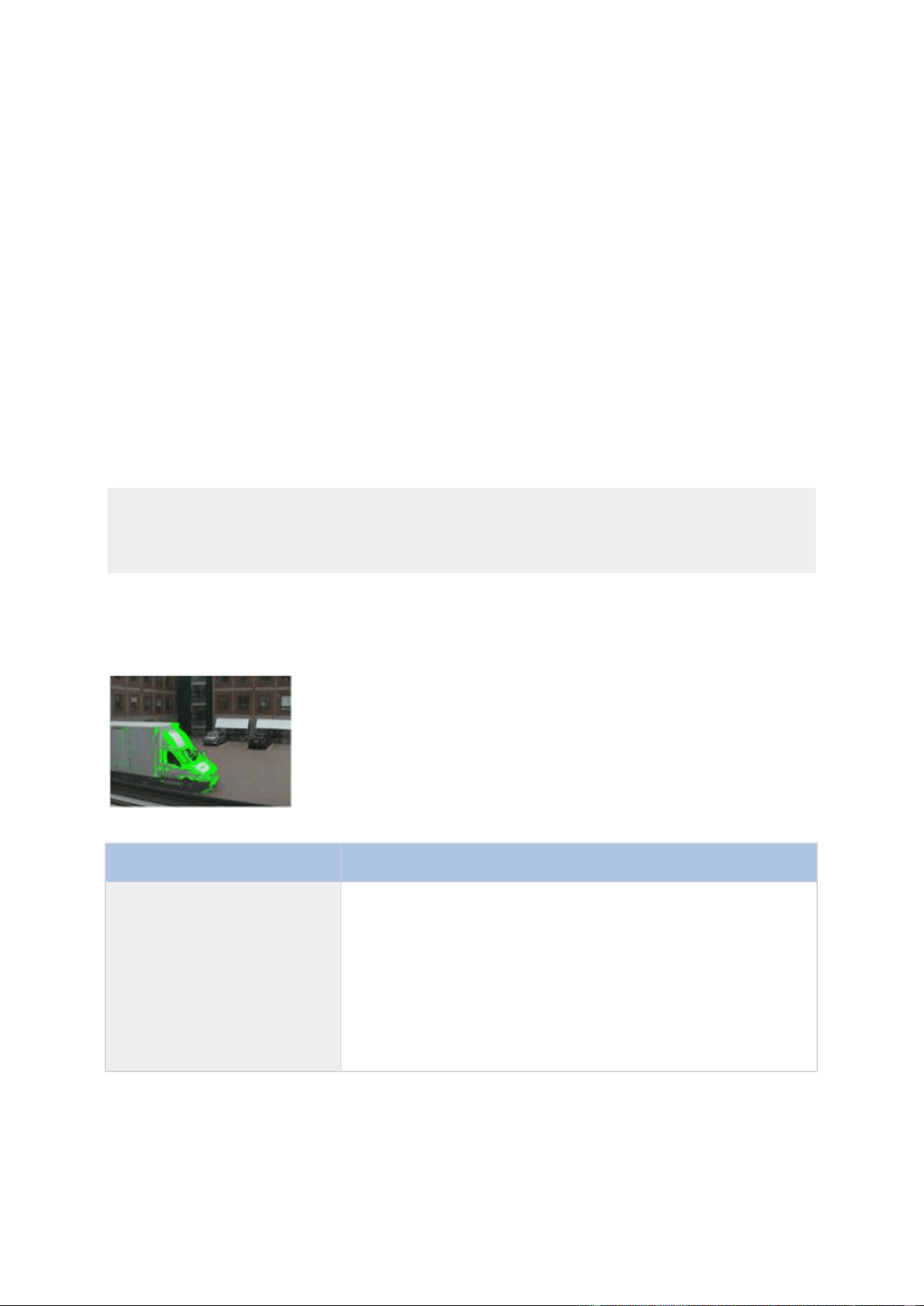
XProtect Professional VMS 2016 R3 - Administrator Manual
Getting started
59
If you use the Exclude All button, you can quickly select all grid sections in the preview. This can
be a good idea if you want to disable motion detection in most areas of the preview, in which case
you can clear the few sections in which you do not want to disable motion detection. With the
Include All button, you can quickly clear all sections.
Adjust motion detection: Motion detection
Available functionality depends on the system you are using. See the Product comparison chart (on
page 11) for more information.
Motion detection is a key element in most surveillance systems. Depending on your configuration,
motion detection settings may determine when video is recorded (saved on the surveillance system
server), when notifications are sent, when output (a light or siren) is triggered and more.
It is important that you find the best possible motion detection settings for each camera to avoid
unnecessary recordings, notifications and more. Depending on the physical location of your
cameras, it is a good idea to test settings under different physical conditions (day/night,
windy/calm weather and similar conditions).
Cameras that do not support multiple simultaneous video streams cannot connect to the
surveillance server and the Management Application at the same time. Milestone recommends that
you stop (see "Start and stop services" on page 168) the Recording Server service when you
configure such devices for motion detection and PTZ. See also View video from cameras in
Management Application (on page 44).
You can configure motion detection settings for each camera, or for several cameras at once. Use
the list in the left pane of the wizard window to select cameras. To select several cameras at a
time, press CTRL or SHIFT while you select. When you select a camera, you see a preview from
that camera. If you select several cameras, you see a preview from the last camera you select. A
green area in the preview indicates motion.
Name
Description
Sensitivity
Adjust the Sensitivity slider so that irrelevant background noise
is filtered out, and only real motion is shown in green.
Alternatively, specify a value between 0 and 256 in the field next
to the slider to control the sensitivity setting.
The slider determines how much each pixel must change before it
is regarded as motion. With a high sensitivity, very little change
in a pixel is required before it is regarded as motion. The more
you drag the slider to the left, the more of the preview becomes
green. This is because with high sensitivity, even the slightest
pixel change is regarded as motion.

XProtect Professional VMS 2016 R3 - Administrator Manual
Getting started
60
Name
Description
Motion
Adjust the Motion slider so that motion detection is only
triggered by the required level of motion. The selected motion
level is indicated by the black vertical line in the Level bar above
the sliders. The black vertical line serves as a threshold. When
motion is above (to the right of) the selected level, the bar
changes color from green to red, indicating a positive motion
detection.
Alternatively, specify a value between 0 and 10000 in the field on
the left to control the motion setting.
The more you drag the slider to the left, the more positive motion
detections you see because less change will be needed to trigger
a positive motion detection. The number of positive motion
detections may also affect the amount of video you record, the
amount of notifications you receive and more.
Detection interval
Specify how often motion detection analysis is carried out on
video from the camera. The default is every 240 milliseconds
(close to once a quarter of a second). The interval is applied
regardless of your cameras' frame rate settings.
Adjusting this setting can help lower the amount of system
resources used on motion detection.
Detection resolution
Specify whether the full image or a selected percentage of the
image should be analyzed. For example, by specifying 25%,
every fourth pixel is analyzed instead of all pixels, reducing the
system resources used but also offering less accurate motion
detection.
Keyframe Only
Select Keyframe only if you want motion detection to take place
only on keyframes of the video stream to reduce the system
resources used on motion detection.
Manage user access wizard
Use the Manage user access step to add individual users so they can access the system and its
clients. The access summary at the end of the wizard lists the cameras your users have access to.
Important: When you use the wizard, all users you add get access to all cameras, including any
new cameras added at a later stage. You can, however, specify access settings, users and user
rights (see "Configure user and group rights" on page 161) separately, see Configure server access
(on page 156). You cannot add users to groups (see "Add user groups" on page 161).
Manage user access: Basic and Windows users
Active Directory
®
is supported in XProtect Enterprise 2013+ and XProtect Professional 2013+ only.
You can add client users in two ways. You can combine these if you need to.

XProtect Professional VMS 2016 R3 - Administrator Manual
Getting started
61
Name
Description
Basic user
Create a dedicated surveillance system user account with basic
user name and password authentication for each individual user.
Windows user
Import users defined locally on the server or from Active
Directory, and authenticate them based on their Windows login.
You must define users as local PC users on the server and disable simple file sharing on the server.
Add Basic users
1. Specify a user name and password, and click the Add Basic User button. Repeat as
required.
Add Windows users
1. Click Add Windows User... to open the Select Users or Groups dialog. You can only
make selections from the local computer, even if you click the Locations... button.
2. In Enter the object names to select, enter the user name(s), then use the Check
Names feature to verify the user name. If you enter several user names, separate each
name with a semicolon. Example: Brian; Hannah; Karen; Wayne.
3. When done, click OK.
Important: When a user who has been added from a local database logs in with a client, the user
should not specify any server name, PC name, or IP address as part of the user name. Example of
a correctly specified user name: USER001, not: PC001/USER001. The user should, of course, still
specify a password and any relevant server information.
Manage user access: Access summary
The access summary lists which cameras your users have access to. When you use the wizard, all
users you have added have access all to cameras, including any new cameras added at a later
stage. You can, however, limit individual users' access to cameras by changing their individual
rights (see "Configure user and group rights" on page 161).

XProtect Professional VMS 2016 R3 - Administrator Manual
Advanced configuration
62
Advanced configuration
Hardware devices
About hardware devices
You add cameras and other hardware devices, such as video encoders, to your system through the
Add Hardware Devices... wizard (see "Add hardware wizard" on page 46). If microphones or
speakers are attached to a hardware device, they are automatically added as well, if your software
version supports this.
About microphones
In your system, Microphones are typically attached to hardware devices, and therefore physically
located next to cameras. Operators, with the necessary rights, can listen to recordings through
XProtect Smart Client if the computer running XProtect Smart Client has speakers attached. You
manage microphones on your system, meaning you can always manage the microphones attached
to cameras, not microphones attached to XProtect Smart Client operators' computers.
If you have added more microphones to your system than you need, you can hide the ones you do
not need by right-clicking the relevant microphone or speaker and select Hide. If you need the
hidden microphone again, you can right-click the overall microphone icon and select Show Hidden
Items.
About speakers
Speakers are attached to devices, and typically physically located next to cameras. They can
typically transmit information to people near a camera. Operators with the necessary rights can
talk through speakers using XProtect Smart Client provided the computer running XProtect Smart
Client has a microphone attached.
Example: An elevator is stuck. Through a camera mounted in the elevator, XProtect Smart Client
operators can see that there is an elderly lady in the elevator. A microphone attached to the
camera records that the lady says: “I am afraid. Please help me out!” Through a speaker attached
to the camera, operators can tell the lady that: “Help is on its way. You should be out in less than
fifteen minutes.”
If you have added more speakers to your system than you need, you can hide the ones you do not
need by right-clicking the relevant peaker and select Hide. If you need the hidden speaker again,
you can right-click the overall speaker icon and select Show Hidden Items.
About recording audio
If you record audio, it is important that you note the following:
Your system only records incoming audio (from microphones). The system does not record
outgoing audio (from speakers).
Audio recording affects video storage capacity. The system records audio to the associated
camera’s database. Therefore, it is important to bear in mind that the database is likely to

XProtect Professional VMS 2016 R3 - Administrator Manual
Advanced configuration
63
become full earlier if you record audio and video than if you only record video. The fact that
the database becomes full is not in itself a problem since your system automatically
archives data if the database becomes full. However, you may need additional archiving
space if you record audio.
Example: If you use MPEG4, each one-second video GOP (Group Of Pictures) are stored
in one record in the database. Each second of audio is stored in one record in the
database. This reduces the database’s video storage capacity to half its capacity,
because half of the database’s records is used for storing audio. Consequently, the
database runs full sooner, and automatic archiving takes place more often than if you
were only recording video.
Example: If you use MJPEG, audio is stored in one record for every JPEG for as long as
the audio block size does not exceed the time between the JPEGs. In extreme cases,
this reduces the database’s video storage capacity to half its capacity, because half of
the database’s records is used for storing audio. If you use very high frame rates, which
means less time between each JPEG, a smaller portion of the database is used for
storing audio records, and consequently a larger portion is available for storing video.
The result is that the database runs full sooner, and automatic archiving takes place
more often than if you were only recording video.
The above examples are simplified. The exact available video storage capacity also depends on
GOP/JPEG and audio kilobyte size.
About dedicated input/output devices
You can add a number of dedicated input/output (I/O) hardware devices to your system. For
information about which I/O hardware devices your system supports, see the release notes.
When you add I/O hardware devices, input on them can be used for generating events in your
system and events in your system can be used for activating output on the I/O hardware devices.
This means that you can use I/O hardware devices in your events-based system setup in the same
way as a camera.
With certain I/O hardware devices, the surveillance system must regularly check the state of the
hardware devices' input ports to detect whether input has been received. Such state checking at
regular intervals is called polling. The interval between state checks, called a polling frequency,
is specified as part of the general ports and polling properties (see "Ports and polling" on page
115). For such I/O hardware devices, the polling frequency should be set to the lowest possible
value (one tenth of a second between state checks). For information about which I/O hardware
devices require polling, see the release notes.
Show or hide microphones or speakers
If you have added more microphones or speakers to your system than you need, you can hide the
ones you do not need by right-clicking the relevant microphone or speaker and select Hide. If you
need the hidden microphone/speaker again, you can right-click the overall microphone or speaker
icon and select Show Hidden Items.
Configure hardware devices
Once you have added hardware devices, you can specify/edit device-specific properties including:
the IP address, which video channels to use, which COM ports to use for controlling attached PTZ
cameras and whether to use Fisheye lens technology.

XProtect Professional VMS 2016 R3 - Administrator Manual
Advanced configuration
64
1. Expand Advanced Configuration, expand Hardware Devices, right-click the relevant
hardware device, and select Properties.
2. Specify Name and video channels, Network, device type and license (see "Network, device
type, and license" on page 67), PTZ device (see "PTZ device (properties)" on page 68), and
Fisheye lens properties as required.
3. Save your configuration changes by clicking Save in the yellow notification bar in the
upper-right corner of the Management Application.
Delete/disable hardware devices
Important: If you delete a hardware device, you not only delete all cameras, speakers and
microphones attached to the hardware device. You also delete any recordings from cameras on the
hardware device.
1. Expand Advanced Configuration, expand Hardware Devices, right-click the hardware
device you want to delete, and select Delete Hardware device.
2. Confirm that you want to delete the hardware device and all its recordings.
3. Save your configuration changes by clicking Save in the yellow notification bar in the
upper-right corner of the Management Application.
4. Restart (see "Start and stop services" on page 168) the Recording Server service.
Alternately, you can also consider disabling the individual cameras, speakers or microphones
connected to the hardware device:
1. Expand Advanced Configuration, expand Hardware Devices, and expand the relevant
hardware device.
2. Right-click the camera, microphone or speaker that you want to disable, and select
Disable.
3. Save your configuration changes by clicking Save in the yellow notification bar in the
upper-right corner of the Management Application.
4. Restart (see "Start and stop services" on page 168) the Recording Server service.
About replacing hardware devices
You can replace a hardware device that you have added and configured on your system with a new
one, for example to replace a physical camera on your network.
Open the Replace Hardware Device wizard (see "About the Replace Hardware Device wizard" on
page 65), which helps you through the entire replacement process on the surveillance system
server, including:
Detecting the new hardware device
Specifying license for the new hardware device
Deciding what to do with existing recordings from the old hardware device

XProtect Professional VMS 2016 R3 - Administrator Manual
Advanced configuration
65
About the Replace Hardware Device wizard
Use the Replace Hardware Device wizard to replace a hardware device that you have previously
added to and configured on your surveillance system. To open the Replace Hardware Device
wizard, right-click the device that you want to replace and select Replace Hardware Device. The
wizard is divided into the New hardware device information page and the database action page.
New hardware device information
Specify details about the new hardware device:
IP Address
The IP address or host name of the hardware device.
Port
The Port number on which to scan. The default is port 80.
If a hardware device is located behind a NAT-enabled router or a
firewall, you may need to specify a different port number. In such
cases, remember to configure the router/firewall so it maps the
port and IP address used by the hardware device.
User Name
The user name for the hardware device's administrator account.
Many organizations use the hardware device manufacturer's
default user names for their hardware devices. If that is the case
in your organization, select "<default>". Do not type a
manufacturer's default user name as this can be a source of
error, trust that your system knows the manufacturer's default
user name.
You can also select other typical user names, such as admin or
root, from the list. Type a new user name if you want a user
name which is not on the list.
Password
The password required to access the administrator account. Some
hardware devices do not require user name/password for access.
Device driver
To specify which device driver to use for the new hardware device, you can:
Select the video device driver in the Hardware device type list, and then click Auto-
detect/Verify Hardware Device Type to verify that the driver matches the hardware
device.
- or -
Click Auto-detect/Verify Hardware Device Type to automatically detect and verify the
right driver.
When the right driver is found, the Serial number (MAC address) field displays the MAC address
of the new hardware device. When done, click Next.
Camera and database action
On the last page of the Replace Hardware wizard, decide what to do with the camera and the
database containing recordings from the camera attached to the old hardware device. For multi-
camera devices, such as video encoders, you must decide what to do for each video channel on the
new hardware device.

XProtect Professional VMS 2016 R3 - Administrator Manual
Advanced configuration
66
The table in the left side of the wizard page lists available video channels on the new hardware
device. For a regular single-camera hardware device, there are only one video channel. For video
encoders, there are typically several video channels.
1. For each video channel, use the table's Inherit column to select which camera from the old
hardware device should be inherited by the new hardware device.
2. Decide what to do with camera databases. You have three options:
Inherit existing database(s): The cameras you selected to be inherited by the new
hardware device inherit camera names, recordings databases as well as any archives
from the old hardware device. Databases and archives are renamed to reflect the new
hardware device's MAC address and video channels. The rights of users with access to
the inherited cameras are automatically updated so they can view both old and new
recordings. Users do not notice the hardware device replacement since camera names
remain the same.
Delete the existing database(s): The databases of the cameras you selected to be
inherited by the new hardware device are not deleted. New databases are created for
future recordings, but it is not possible to view recordings from before the hardware
replacement.
Leave the existing database(s): The databases of the cameras you selected to be
inherited by the new hardware device are not deleted. New databases are created for
future recordings, but even though the old databases still exist on the System server, it
is not possible to view recordings from before the hardware replacement. Should you
later want to delete the old databases, you must delete this manually.
3. If the new hardware device has fewer video channels than the old hardware device, it is not
possible for the new hardware device to inherit all cameras from the old hardware device.
When that is the case, you are asked what to do with the databases of cameras that could
not be inherited by the new hardware device. You have two options:
Delete the databases for the cameras that are not inherited: The databases of
the cameras that could not be inherited by the new hardware devices are deleted. It is
not possible to view recordings from before the hardware replacement. New databases
are, of course, created for future recordings by the new hardware devices.
Leave the databases for the cameras that are not inherited: The databases of the
cameras that could not be inherited by the new hardware devices are not deleted. Even
though the old databases still exist on the System server, it is not possible to view
recordings from before the hardware replacement. Should you later want to delete the
old databases, you must delete this manually. New databases will, of course, be created
for future recordings by the new hardware devices.
4. Click Finish. When you are ready, restart the Recording Server service. The hardware
replacement are not evident in clients until you restart the Recording Server service.
Speaker properties
When you configure video and recording (see "About video and recording configuration" on page
69) for specific cameras, you can determine when to record audio. Your choice applies for all
cameras on your system.
Enabled
Speakers are by default enabled, meaning they can transfer audio
to your system. If required, you can disable an individual
speaker, in which case no audio is transferred from the speaker
to the system.

XProtect Professional VMS 2016 R3 - Administrator Manual
Advanced configuration
67
Speaker name
The name as it appears in the Management Application as well as
in clients. You can overwrite the existing name with a new one.
Names must be unique, and must not contain any of these special
characters: < > & ' " \ / : * ? | [ ]
Hardware properties
Hardware name and video channels
When you configure hardware devices, specify the following properties:
Hardware name
The name as it appears in the Management Application as well as
in clients. You can overwrite the existing name with a new one.
Names must be unique, and must not contain any of these special
characters: < > & ' " \ / : * ? | [ ]
Video channel # enabled
Enable/disable each of the selected hardware device's video
channels. Many hardware devices only have a single video
channel, in which case only one channel is listed.
Other hardware devices, typically video encoder devices, have
several video channels.
Network, device type, and license
When you configure hardware devices (on page 63), specify the following properties:
IP Address
The IP address or host name of the hardware device.
HTTP Port
The port to use for HTTP communication with the hardware
device. The default is port 80. To use the default port, select Use
default HTTP port.
FTP port
The port to use for FTP communication with the hardware device.
The default port is port 21. To use the default port, select Use
default FTP port.
User name
Only relevant when you have selected Server requires login.
Specify the user name required for using the SMTP server.
User Name
The user name for the hardware device's administrator account.
Many organizations use the hardware device manufacturer's
default user names for their hardware devices. To do so, select
"<default>". Do not type a manufacturer's default user name as
this can be a source of error. Trust that your system knows the
manufacturer's default user name.
You can also select other typical user names, such as admin or
root, from the list. Type a new user name if you want a user
name which is not on the list.

XProtect Professional VMS 2016 R3 - Administrator Manual
Advanced configuration
68
Password
Edit the password. Remember to repeat the password to be sure
you have specified it correctly.
You can only edit this if the selected user is a basic user.
Hardware type
Read-only field displaying the type of video device driver used for
communication with the hardware device.
Serial number (MAC
address)
Read-only field displaying the serial number of device. The serial
number is usually identical to the 12-character hexadecimal MAC
address of the hardware device (example: 0123456789AF).
License information
The current license status for the hardware.
Replace Hardware Device
Opens a wizard (see "About the Replace Hardware Device wizard"
on page 65) that you can use to replace the selected hardware
device with another one if you need to.
This can be relevant if you replace a physical camera on your
network. The wizard helps you take all relevant issues into
account including deciding what to do with recordings from
cameras attached to the old hardware device.
PTZ device (properties)
The PTZ device tab is only available if you configure (see "Configure hardware devices" on page
63) video encoder hardware devices on which you can use PTZ:
Connected cameras have
Pan-tilt-zoom capabilities
Select the check box if any of the cameras attached to the video
encoder device is a PTZ camera.
PTZ type on COM#
If a PTZ camera is controlled through a COM port, select the
relevant option. Options are device-specific, depending on which
PTZ protocols the device uses. Select None if you have no PTZ
cameras controlled through COM ports.
The table in the lower half of the dialog contains a row for each video channel on the hardware
device. First row from the top corresponds to video channel 1, second row from the top
corresponds to video channel 2 and so on.
Name
Name of the camera attached to the relevant video channel.
Type
Select whether the camera on the selected camera channel is
fixed or moveable:
Fixed: Camera is a regular camera mounted in a fixed
position
Moveable: Camera is a PTZ camera
Port
Available only if Moveable is selected in the Type column. Select
which COM port on the video encoder to use for controlling the
PTZ camera.
XProtect Professional VMS 2016 R3 - Administrator Manual
Advanced configuration
69
Port Address
Available only if Moveable is selected in the Type column. Lets
you specify port address of the camera. The port address will
normally be 1. If using daisy chained PTZ cameras, the port
address will identify each of them, and you should verify your
settings with those recommended in the documentation for the
camera.
Cameras and storage information
About video and recording configuration
Once you have added hardware devices and attached cameras, you can configure video and
recording settings in three ways:
Name
Description
Wizard-driven
Guided configuration where you can specify video, recording and
archiving settings for all your cameras.
General
Specify video, recording and shared settings (such as dynamic
archiving paths and whether to record audio or not) for all your
cameras.
Camera-specific
Specify video, recording and camera-specific settings (such as
event notification, PTZ preset positions and fisheye view areas)
for each individual camera.
About database resizing
In case recordings for a camera get bigger than expected, or the available drive space is suddenly
reduced in another way, an advanced database resizing procedure automatically takes place:
If archives (see "About archiving" on page 124) are present on the same drive as the
camera's database, the oldest archive for all cameras archived on that drive is moved to
another drive (moving archives is only possible if you use dynamic archiving (see "Dynamic
path selection (properties)" on page 76), with which you can archive to several different
drives) or—if moving is not possible—deleted.
If no archives are present on the drive containing the camera's database, the size of all
camera databases on the drive is reduced by deleting a percentage of their oldest
recordings, temporarily limiting the size of all databases.
When the Recording Server service (see "About services" on page 166) is restarted upon such
database resizing, the original database sizes are used. Therefore, you should make sure to solve
the drive size problem. Should the database resizing procedure take place, you are informed on-
screen in XProtect Smart Client, in log files, and, if set up, through notifications.
About motion detection
Motion detection settings are linked to the Recording properties settings for the camera under
which you can enable and configure motion detection for the selected camera. Motion detection

XProtect Professional VMS 2016 R3 - Administrator Manual
Advanced configuration
70
configuration is a key element in your system: your motion detection configuration determines
when the system generates motion events and typically also when video is recorded.
Motion detection is enabled as default. Disabling it improves the CPU and RAM performance of your
system, but can also affect your motion detection, event and alarm management.
Time spent on finding the best possible motion detection configuration for each camera helps you
avoid unnecessary recordings. Depending on the physical location of the camera, it may be a good
idea to test motion detection settings under different physical conditions such as day/night and
windy/calm weather.
Before you configure motion detection for a camera, Milestone recommends that you have
configured the camera's image quality settings, for example resolution, video codec and stream
settings. If you later change image quality settings, you should always test any motion detection
configuration afterwards.
In the following two tables, you can see the differences between enabling (table 1) and disabling
(table 2) built-in motion detection for a camera.
Enabled motion detection
Recording
properties setting
Recordings
Motion-based
events
Non-motion
based events
Sequences
Always
Yes
Yes
Yes
Yes
Never
No
Yes
Yes
No
Built-in Motion
Detection
Yes
Yes
Yes
Yes
Built-in Motion
Detection & Event or
Event only
Yes
Yes
Yes
Yes
Disabled motion detection
Camera's recording
settings
Recordings
Motion-based
events
Non-motion
based events
Sequences
Always
Yes
No
Yes
No
Never
No
No
Yes
No
Built-in Motion
Detection
No
No
Yes
No
Built-in Motion
Detection and Event
or Event only
Yes (depending
on settings)
No
Yes (depending
on settings)
No
Motion detection sensitivity
Motion detection is per default set up for dynamic sensitivity. However, you can also adjust the
sensitivity level manually under Motion Detection properties.
Milestone recommends that you do not enable manual sensitivity because:
With dynamic sensitivity, the system calculates and optimizes the sensitivity level
automatically and suppresses the motion detections that come from noise in the images.
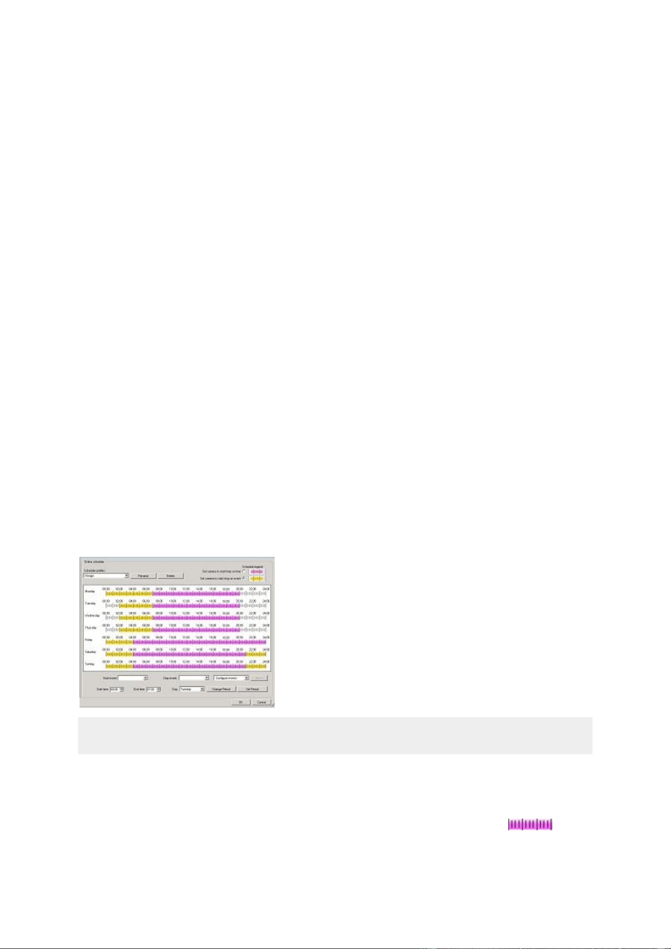
XProtect Professional VMS 2016 R3 - Administrator Manual
Advanced configuration
71
Dynamic sensitivity improves motion detection at nighttime, where the noise in the images
often triggers false motion.
The system is not overloaded from too much recording.
The users are not missing results from too little recording.
Motion detection and PTZ cameras
Motion detection generally works the same way for pan-tilt-zoom (PTZ) cameras as it does for
regular cameras. However, you cannot configure motion detection separately for each of a PTZ
camera's preset positions.
About motion detection and PTZ cameras
Motion detection generally works the same way for pan-tilt-zoom (PTZ) cameras as it does for
regular cameras. However, you cannot configure motion detection separately for each of a PTZ
camera's preset positions.
In order to activate unwanted recordings, notifications and more, the system automatically disables
motion detection while a PTZ camera moves between two preset positions. After a number of
seconds has passed, the system automatically enables motion detection again. This period of time
is known as the transition time and is specified on the PTZ camera's PTZ patrolling properties (see
"PTZ patrolling (properties)" on page 102).
Configure camera-specific schedules
Available functionality depends on the system you are using. See the Product comparison chart (on
page 11) for more information.
If you base your schedule profile, or parts of it, on events within periods of time: remember to
select Start event and Stop event from the lists below the calendar section.
Use the Configure events list located below the other fields to define events that suit your needs.
The fact that a camera transfers video to your system does not necessarily mean that video from
the camera is recorded. Recording is configured separately, see Configure video and recording (see
"About video and recording configuration" on page 69).
For each camera, you can create schedule profiles based on:
Online periods
Periods of time (example: Mondays from 08.30 until 17.45), shown in pink:

XProtect Professional VMS 2016 R3 - Administrator Manual
Advanced configuration
72
Events within periods of time (example: from Event A occurs until Event B occurs Mondays
from 08.30 until 17.45), shown in yellow:
The two options can be combined , but they cannot overlap in time.
Speedup
Periods of time (example: Mondays from 08.30 until 17.45), shown in olive green:
E-mail notification
Periods of time (example: Mondays from 08.30 until 17.45), shown in blue:
PTZ patrolling
Periods of time (example: Mondays from 08.30 until 17.45), shown in red:
If use of one patrolling profile is followed immediately by use of another, run your mouse
pointer over the red bar to see which patrolling profile applies when.
SMS notification
Periods of time (example: Mondays from 08.30 until 17.45), shown in green:
Set up a profile
1. In the Schedule Profiles list, select Add new....
2. In the Add Profile dialog, enter a name for the profile. Names must not contain any of
these special characters: < > & ' " \ / : * ? | [ ]
3. In the top right corner of the dialog, select Set camera to start/stop on time to base
subsequent settings on periods of time or Set camera to start/stop on event to base
subsequent settings on events within periods of time.
4. In the calendar section, place your mouse pointer at a required start point, then hold down
the left mouse button, drag the mouse pointer and release at the required end point.
You specify each day separately.
You specify time in increments of five minutes. The system helps you by showing the
time over which your mouse pointer is positioned.
If you base your schedule profile, or parts of it, on events within periods of time: remember to
select Start event and Stop event from the lists below the calendar section.
Use the Configure events list located below the other fields to define events that suit
your needs.

XProtect Professional VMS 2016 R3 - Administrator Manual
Advanced configuration
73
To delete an unwanted part of a schedule profile, right-click it and select Delete.
To quickly fill or clear an entire day, double-click the name of the day.
As an alternative to dragging inside the calendar section, use the Start time, End time
and Day fields, then the Change Period or Set Period button as required. When using
the Start time and End time fields, remember that time is specified in increments of
five minutes. You cannot specify a period shorter than five minutes, and you can only
use times like 12:00, 12.05, 12:10, 12:15, etc. If you specify a time outside of the five-
minute intervals, such as 12:13, you will get an error message.
Configure when cameras should do what
Available functionality depends on the system you are using. See the Product comparison chart (on
page 11) for more information.
Use the scheduling feature to configure when:
Cameras should be online and transfer video to your system.
Cameras should use speedup to use a higher than normal frame rate
You want to receive email and/or SMS notifications regarding cameras
PTZ cameras should patrol, and according to which patrolling profile
Archiving should take place
See Configure general scheduling and archiving (on page 129) and Configure camera-specific
schedules (on page 71).
Configure motion detection
To configure motion detection, do the following:
1. Expand Advanced Configuration > Cameras and Storage Information, right-click the
relevant camera > Properties.
2. In the Camera Properties window, select the Recording Properties tab > select the
relevant settings (see "About motion detection" on page 69).
3. Select the Motion Detection tab. If there are any areas to exclude from motion detection
(for example, if the camera covers an area where a tree is swaying in the wind), you can
exclude that area (see "Adjust motion detection: Exclude regions" on page 58) by selecting
it with your mouse.
4. Fill in the relevant properties (see "Motion detection & exclude regions" on page 98). Note
that there are some differences in motion-detection behavior for PTZ cameras (see "About
motion detection and PTZ cameras" on page 71).
Disable or delete cameras
All cameras are enabled by default. This means that video from the cameras can be transferred to
your system if the cameras are scheduled to be online (see "Online period" on page 133).
To disable a camera:
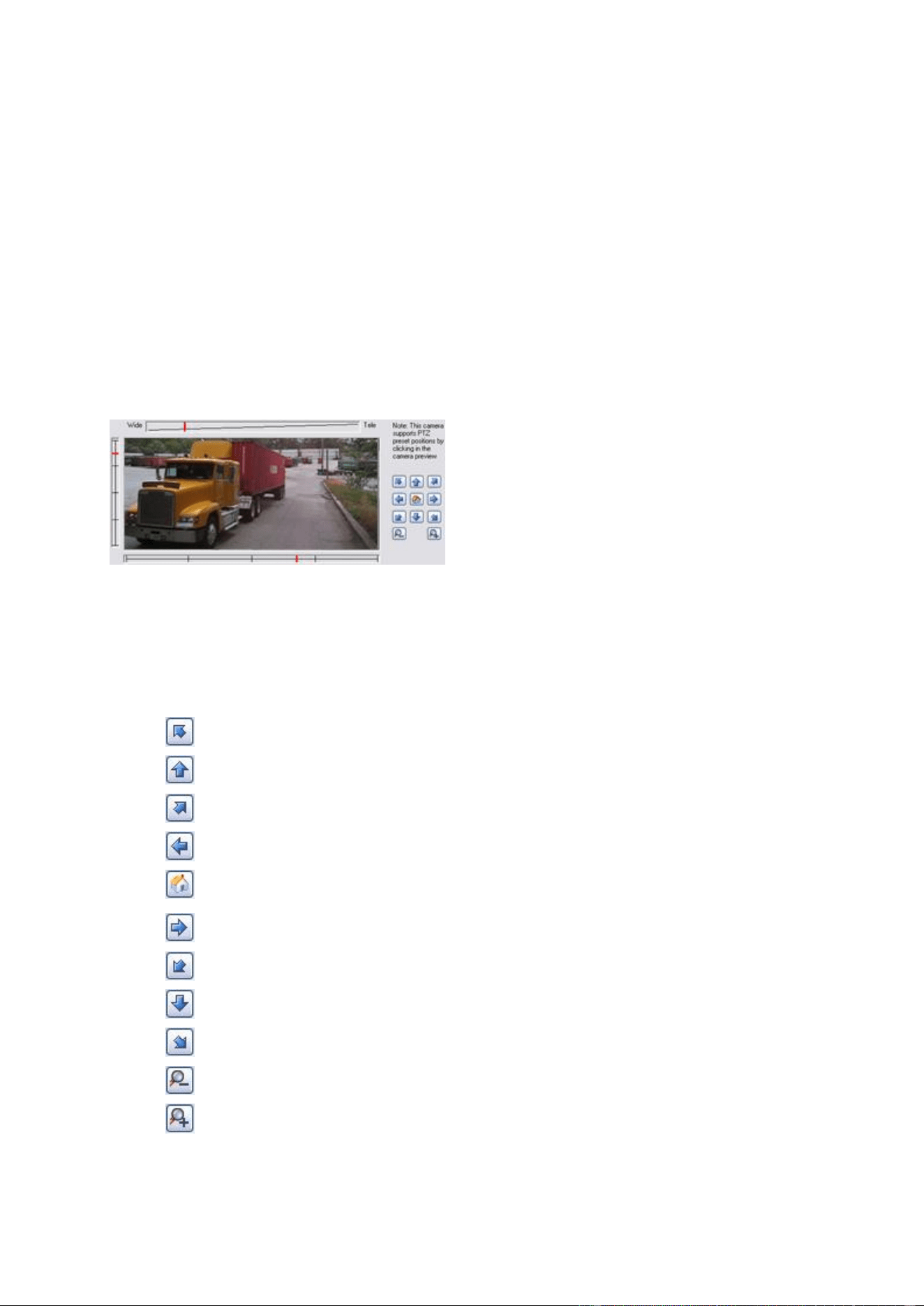
XProtect Professional VMS 2016 R3 - Administrator Manual
Advanced configuration
74
1. Expand Advanced Configuration, expand Cameras and Storage Information, double-
click the camera you want to disable, and clear the Enabled box.
2. Save your configuration changes by clicking Save in the yellow notification bar in the
upper-right corner of the Management Application.
To delete a camera, you have to delete the hardware device (see "Delete/disable hardware
devices" on page 64). If you delete the hardware device, you also delete any attached microphones
or speakers. If you do not want this, consider disabling the camera instead.
Move PTZ type 1 and 3 to required positions
For PTZ types 1 and 3, you can move the PTZ camera to required positions in several different
ways:
1. Click the required position in the camera preview (if supported by the camera).
2. Use the sliders located near the camera preview to move the PTZ camera along each of its
axes: the X-axis (for panning left/right), the Y-axis (for tilting up/down), and the Z-axis (for
zooming in and out; to zoom in, move the slider towards Tele; to zoom out, move the
slider towards Wide).
3. Use the navigation buttons:
Moves the PTZ camera up and to the left
Moves the PTZ camera up
Moves the PTZ camera up and to the right
Moves the PTZ camera to the left
Moves the PTZ camera to its home position (that is
default position)
Moves the PTZ camera to the right
Moves the PTZ camera down and to the left
Moves the PTZ camera down
Moves the PTZ camera down and to the right
Zooms out (one zoom level per click)
Zooms in (one zoom level per click)

XProtect Professional VMS 2016 R3 - Administrator Manual
Advanced configuration
75
Recording and storage properties
Recording and archiving paths (properties)
When you configure video and recording (see "About video and recording configuration" on page
69), you can specify certain properties for many cameras in one go. Either in order to speed up
things, or because the relevant properties are shared by all cameras rather than being specific to
individual cameras.
You can edit all properties on a white background. You cannot edit properties on a light blue
background. Note that all of the properties can also be specified individually for each camera.
Template
The template can help you configure similar properties quickly.
Say you have 20 cameras and you want to change the recording
path, archiving path, and retention time for all of them. Instead
of having to enter the same three pieces of information 20 times,
you can simply enter them once in the template, and then apply
the template to the 20 cameras with only two clicks.
Apply Template
Select which cameras you want to apply the template for. Use
one of the two Set buttons to actually apply the template.
Camera Name
The name as it appears in the Management Application as well as
in clients. You can overwrite the existing name with a new one.
Names must be unique, and must not contain any of these special
characters: < > & ' " \ / : * ? | [ ]
Shortcut
Users of XProtect Smart Client can take advantage of keyboard
shortcuts, some of which let the users toggle between viewing
different cameras. Such shortcuts include numbers which are
used to identify each camera.
Shortcut numbers must be unique for each camera. A camera
shortcut number must not contain any letters or special
characters, and must not be longer than eight digits.
Examples of correct camera shortcut numbers: 3, 12345678.
Examples of incorrect camera shortcut numbers: Cam#3,
123456789.
More information about using the keyboard shortcuts is available
in the separate documentation for XProtect Smart Client.

XProtect Professional VMS 2016 R3 - Administrator Manual
Advanced configuration
76
Recording Path
Path to the folder in which the camera's database should be
stored. Default is C:\MediaDatabase. To browse for another
folder, click the browse icon next to the required cell. You can
only specify a path to a folder on a local drive. You cannot
specify a path to a network drive. If you use a network drive, you
cannot save recordings if the network drive becomes unavailable.
If you change the recording path, and you have existing
recordings at the old location, you are asked whether you want to
move the recordings to the new location, leave them at the old
location, or delete them.
If you have several cameras, and several local drives are
available, you can improve performance by distributing individual
cameras' databases across several drives.
Archiving Path
Only editable if not using dynamic paths for archiving (see "About
archiving" on page 124). Path to the folder in which the camera's
archived recordings should be stored. Default is
C:\MediaDatabase.
To browse for another folder, click the browse icon next to the
relevant cell. If you change the archiving path, and there are
existing archived recordings at the old location, you are asked
whether you want to move the archived recordings to the new
location (recommended), leave them at the old location, or delete
them. Note that if you move archived recordings, your system
also archives what is currently in the camera database. In case
you wonder why the camera database is empty just after you
have moved archived recordings, this is the reason.
Retention time
Total amount of time for which you want to keep recordings from
the camera (that is, recordings in the camera's database as well
as any archived recordings). The default retention time is 7 days.
Retention time covers the total amount of time you want to keep
recordings for. In earlier versions of your surveillance system,
you specified time limits separately for the database and
archives.
Camera
Click the Open button to configure detailed and/or camera-
specific settings (such as event notification, PTZ preset positions,
and fisheye view areas) for the selected camera.
Select All
Click button to select all cameras in the Apply Template column.
Clear All
Click button to clear all selections in the Apply Template
column.
Set selected template value
on selected cameras
Apply only a selected value from the template to selected
cameras.
Set all template values on
selected cameras
Apply all values from the template to selected cameras.

XProtect Professional VMS 2016 R3 - Administrator Manual
Advanced configuration
77
Dynamic path selection (properties)
When you configure video and recording (see "About video and recording configuration" on page
69), you can specify certain properties for many cameras in one go. In the case of dynamic path
selection, all cameras share the properties.
With dynamic archiving (see "About archiving" on page 124) paths, you specify a number of
different archiving paths, usually across several drives. If the path containing the system database
is on one of the drives you have selected for archiving, the system always tries to archive to that
drive first. If not, the system automatically archives to the archiving drive with the most available
space at any time, provided there is not a camera database using that drive. Which drive has the
most available space may change during the archiving process, and archiving may therefore
happen to several archiving drives during the same process. This fact has no impact on how users
find and view archived recordings.
Dynamic archiving paths are general for all your cameras. You cannot configure dynamic archiving
paths for individual cameras.
Enable dynamic path
selection archives
Enables the use of dynamic path selection, allowing you to select
which paths you want to use. The list of selectable paths initially
represents all drives on the server, both local and mapped drives.
You can add further paths with the New path feature below the
list.
Use
Select particular paths for use as dynamic archiving paths. You
can also select a previously manually added path for removal (see
description of Remove button in the following).
Drive
For example the C:\ drive.
Path
Path to where you save the files, for example C:\ or
\\OurServer\OurFolder\OurSubfolder\.
Drive Size
The total size of the drive.
Free Space
Amount of unused space left on the drive.
New path
Specify a new path, and add it to the list using the Add button.
Paths must be reachable by the surveillance system server, and
you must specify the path using the Universal Naming Convention
(UNC) format, example: \\server\volume\directory\. When the
new path is added, you can select it for use as a dynamic
archiving path.
Add
Add the path specified in the New path field to the list.
Remove
Remove a selected path that you have added manually from the
list. You cannot remove any of the initially listed paths, not even
when they are selected.
Video recording (properties)
When you configure video and recording (see "About video and recording configuration" on page
69), you can specify certain properties for many cameras in one go. Either in order to speed up
things, or because the relevant properties are shared by all cameras rather than being specific to
individual cameras.

XProtect Professional VMS 2016 R3 - Administrator Manual
Advanced configuration
78
The term recording means saving video and, if applicable, audio from a camera in the camera's
database on the surveillance system server. Video/audio is often saved only when there is a reason
to do so, for example as long as motion is detected, when an event occurs and until another event
occurs, or within a certain period of time.
You can edit all properties on a white background. You cannot edit properties on a light blue
background.
Note that you can also specify all of the Video Recording properties individually for each camera
(see "Recording" on page 93).
Name
Description
Template
The template can help you configure similar properties quickly.
Say you have 20 cameras and you want to change the recording
path, archiving path, and retention time for all of them. Instead
of having to enter the same three pieces of information 20 times,
you can simply enter them once in the template, and then apply
the template to the 20 cameras with only two clicks.
Apply Template
Select which cameras you want to apply the template for. Use
one of the two Set buttons to actually apply the template.
Camera Name
The name as it appears in the Management Application as well as
in clients. You can overwrite the existing name with a new one.
Names must be unique, and must not contain any of these special
characters: < > & ' " \ / : * ? | [ ]
Record on
Select under which conditions video from the camera should be
recorded:
Always: Record whenever the camera is enabled and
scheduled to be online. The latter option allows for time-
based recording.
Never: Never record. Live video is shown, but users cannot
play back video from the camera because no video is kept in
the database.
Motion Detection: Select this to record video when motion
is detected. Unless you add post-recording, recording stops
immediately after the last motion is detected.
Event: Select this to record video when an event occurs and
until another event occurs. Use of recording on event requires
that events (see "Overview of events and output" on page
108) have been defined, and that you select start and stop
events. Use the Configure events list located below the other
fields to define events that suit your needs.
Motion Detection and Event: Select this to record video in
which motion is detected, or when an event occurs and until
another event occurs. Remember to select start and stop
events in the neighboring columns.
Start Event
Select the relevant start event. Recording will begin when the
start event occurs (or earlier if using pre-recording; see the
following).
Stop Event
Select the relevant stop event. Recording will end when the stop
event occurs (or later if using post-recording; see the following).

XProtect Professional VMS 2016 R3 - Administrator Manual
Advanced configuration
79
Name
Description
Pre-recording
You can store recordings from periods preceding detected motion
and/or start events. Select check box to enable this feature.
Specify the required number of seconds in the neighboring
column.
Seconds [of pre-recording]
Specify the number of seconds for which you want to record video
from before recording start conditions (that is motion or start
event) are met. Usually, only some seconds of pre-recording is
required, but you can specify up to 65535 seconds of pre-
recording, corresponding to 18 hours, 12 minutes and 15
seconds. However, if specifying a very long pre-recording time,
you can potentially run into a scenario where your pre-recording
time spans scheduled or unscheduled archiving (see "About
archiving" on page 124) times. That can be problematic since
pre-recording does not work well during archiving.
Post-recording
You can store recordings from periods following detected motion
and/or stop events. Select the check box to enable this feature.
Specify the required number of seconds in the neighboring
column.
Seconds [of post-recording]
Specify the number of seconds for which you want to record video
from after recording stop conditions (that is motion or stop event)
are met. Usually, only some seconds of post-recording is
required, but you can specify up to 65535 seconds of post-
recording, corresponding to 18 hours, 12 minutes and 15
seconds.
If you specify a very long post-recording time, you can potentially
run into a scenario where your post-recording time spans
scheduled or unscheduled archiving times. That can be
problematic since post-recording does not work well during
archiving.
Camera
Click the Open button to configure detailed and/or camera-
specific settings (such as event notification, PTZ preset positions,
and fisheye view areas) for the selected camera.
Select All
Click the button to select all cameras in the Apply Template
column.
Clear All
Click the button to clear all selections in the Apply Template
column.
Set selected template value
on selected cameras
Apply only a selected value from the template to selected
cameras.
Set all template values on
selected cameras
Apply all values from the template to selected cameras.
If the camera uses the MJPEG video format
With MJPEG, you can define frame rates for regular as well as speedup modes. If the camera offers
dual stream, you can also enable this.
Note that there are three places where you can set frame rate:
Live Frame Rate - used for the regular recording stream

XProtect Professional VMS 2016 R3 - Administrator Manual
Advanced configuration
80
Live Frame Rate - used when speeding up recordings in connection with motion detection or
similar functionality.
FPS (Frames per second) - used for the additional stream used for live viewing.
Regular frame rate mode:
Frame Rate
Required average frame rate for video from the camera. Select
the number of frames, then select the time unit interval (second,
minute or hour).
Live Frame Rate
Required average frame rate for live video from the camera.
Select the number of frames, then select the time unit interval
(second, minute or hour).
If the camera supports dual stream and dual stream is enabled,
the Live Frame Rate column will be read-only with the value Dual
streaming—which cannot be altered.
Recording Frame Rate
Required average frame rate for recorded video from the camera.
Select the number of frames, then select the time unit interval
(second, minute or hour). The frame rate must be higher than
the frame rate specified under normal mode.
Speedup frame rate mode:
Enable speedup frame rate
The speedup feature lets you use a higher than normal frame rate
if motion is detected and/or an event occurs. When you enable
speedup, further columns for specifying speedup details become
available.
Frame Rate
Speedup frame rate for viewing video from the camera. Select
the number of frames, then select the time unit interval (second,
minute or hour). The frame rate must be higher than the frame
rate specified under normal mode.
On motion
Select this check box to use the speedup frame rates when
motion is detected. The camera will return to the normal frame
rates two seconds after the last motion is detected.
On event
Select this check box to use the speedup frame rates when an
event occurs and until another event occurs. Use of speedup on
event requires that events have been defined, and that you select
start and stop events in the neighboring lists.
Use the Configure events list located below the other fields to
define events that suit your needs.
Start Event
Select required start event. The camera will begin using the
speedup frame rates when the start event occurs.
Stop Event
Select required stop event. The camera will return to the normal
frame rates when the stop event occurs.

XProtect Professional VMS 2016 R3 - Administrator Manual
Advanced configuration
81
Live Frame Rate
Required average frame rate for live video from the camera.
Select the number of frames, then select the time unit interval
(second, minute or hour). The frame rate must be higher than
the frame rate specified under normal mode.
If the camera supports dual stream and dual stream is enabled,
the Live Frame Rate column will be read-only with the value Dual
streaming—which cannot be altered.
Recording Frame Rate
Required average frame rate for recorded video from the camera.
Select the number of frames, then select the time unit interval
(second, minute or hour). The frame rate must be higher than
the frame rate specified under normal mode.
You do not have to base speedup on motion or events. You can also use scheduling (see "Speedup"
on page 133) to configure speedup based on particular periods of time. If you prefer time-based
speedup, you should still enable the use of speedup by selecting the Enable speedup check box.
Dual stream:
Enable dedicated live
stream
This additional stream feature lets you use the alternative stream
of the camera. It enables two independent streams to the
recording server—a stream for live viewing and another stream
for recording purposes, with different resolution, encoding, and
frame rate.
Stream
Select the type of the live stream. Stream settings for viewing
live video and for recording video may very well be different in
order to get the best result.
Resolution
Select the camera's resolution.
FPS
Select the camera's live frame rate per second (FPS)
Important: This feature is only available on cameras supporting dual stream.
If the camera uses the MPEG video format
Available functionality depends on the system you are using. See the Product comparison chart (on
page 11) for more information.
With MPEG, you can define frame rate and other settings:
Frame rate per second
Frame rate for viewing live and recorded video from the camera.
Select number of frames per second.
Record keyframes only
Keyframes stored at specified intervals record the entire view of
the camera, whereas the following frames record only pixels that
change. This helps greatly reducing the size of MPEG files. Select
the check box if you only want to record keyframes. Note that
you can specify exceptions if motion is detected or events occur.

XProtect Professional VMS 2016 R3 - Administrator Manual
Advanced configuration
82
Record all frames on event
Allows you to make exceptions if you have selected to record
keyframes only. Select this check box to record all frames when
an event occurs and until another event occurs. Use of this
feature requires that events have been defined, and that you
select start and stop events in the neighboring lists.
Use the Configure events list located below the other fields to
define events that suit your needs.
Start Event
Use when recording on Event or Motion Detection and
Event. Select the relevant start event. The camera begins
recording all frames when the start event occurs.
Stop Event
Select the relevant stop event. The camera stops recording
keyframes when the stop event occurs.
Dual stream:
Enable dedicated live
stream
This additional stream feature lets you use the alternative stream
of the camera. It enables two independent streams to the
recording server—a stream for live viewing and another stream
for recording purposes, with different resolution, encoding, and
frame rate.
Stream
Select the type of the live stream. Stream settings for viewing
live video and for recording video may very well be different in
order to get the best result.
Resolution
Select the camera's resolution.
FPS
Select the camera's live frame rate per second (FPS)
Important: This feature is only available on cameras supporting dual stream.
Manual recording
When you configure video and recording (see "About video and recording configuration" on page
69), you can specify certain properties for many cameras in one go. In the case of manual
recording, it is because the properties are shared by all cameras.
When manual recording is enabled, XProtect Smart Client users with the necessary rights can
manually start recording if they see something of interest while viewing live video from a camera
which is not already recording. User-driven recording always takes place for a fixed time, for
example for five minutes.
Enable manual recording
Select check box to enable manual recording and specify further
details.
Default duration of manual
recording
Period of time in seconds during which user-driven recording take
place. Default duration is 300 seconds, corresponding to five
minutes.

XProtect Professional VMS 2016 R3 - Administrator Manual
Advanced configuration
83
Maximum duration of
manual recording
The maximum allowed period of time for user-driven recording.
This maximum is not relevant in connection with manual
recording started from XProtect Smart Client, since such manual
recording always takes place for a fixed time.
In some installations, you can also combine manual recording
with third-party applications if integrating these with the system
through an API or similar, and in such cases specifying a
maximum duration may be relevant.
If you are using manual recording in connection with XProtect
Smart Client only, disregard this property.
If manual recording is enabled, this can take place even if recording for individual cameras (see
"Recording" on page 93) is set to Never or Conditionally.
Frame rate - MJPEG
When you configure video and recording (see "About video and recording configuration" on page
69), you can specify certain properties for many cameras in one go. Either in order to speed up
things, or because the relevant properties are shared by all cameras rather than being specific to
individual cameras.
You can edit all properties on a white background. You cannot edit properties on a light blue
background. Note that all of the Frame rate - MJPEG properties can also be specified individually
for each camera (see "Recording" on page 93) using MJPEG.
Template and common properties
Name
Description
Template
The template can help you configure similar properties quickly.
Say you have 20 cameras and you want to change the recording
path, archiving path, and retention time for all of them. Instead
of having to enter the same three pieces of information 20 times,
you can simply enter them once in the template, and then apply
the template to the 20 cameras with only two clicks.
Apply Template
Select which cameras you want to apply the template for. Use
one of the two Set buttons to actually apply the template.
Select All
Click the button to select all cameras in the Apply Template
column.
Clear All
Click the button to clear all selections in the Apply Template
column.
Set selected template value
on selected cameras
Apply only a selected value from the template to selected
cameras.
Set all template values on
selected cameras
Apply all values from the template to selected cameras.
Camera Name
The name as it appears in the Management Application as well as
in clients. You can overwrite the existing name with a new one.
Names must be unique, and must not contain any of these special
characters: < > & ' " \ / : * ? | [ ]

XProtect Professional VMS 2016 R3 - Administrator Manual
Advanced configuration
84
Regular frame rate properties
Specify the following frame rate properties:
Name
Description
Frame Rate
Required average frame rate for video from the camera. Select
the number of frames, then select the time unit interval (second,
minute or hour).
Time Unit
Select required unit for live and recording frame rates (per
second, minute, or hour). Note that you can only select time
bases that let you speed up frame rates. Example: If you have
specified 15 frames per second in normal mode, you cannot
specify 16 frames per minute or hour in speedup mode.
Camera
Click the Open button to configure detailed and/or camera-
specific settings (such as event notification, PTZ preset positions,
and fisheye view areas) for the selected camera.
Live Frame Rate
The required average frame rate for live video from the camera.
Select the number of frames, then select the time unit interval
(second, minute or hour).
If the camera supports dual stream and you have enabled dual
stream, the Live Frame Rate column is read-only with the value
Dual streaming. You cannot change this.
Recording Frame Rate
Required average frame rate for recorded video from the camera.
Select the number of frames, then select the time unit interval
(second, minute or hour). The frame rate must be higher than
the frame rate specified under normal mode.
Speedup frame rate properties
Available functionality depends on the system you are using. See the Product comparison chart (on
page 11) for more information.
Name
Description
Enable Speedup
The speedup feature lets you use a higher than normal frame rate
if motion is detected and/or an event occurs. When you enable
speedup, further columns for specifying speedup details become
available.
Frame Rate
Speedup frame rate for viewing video from the camera. Select
the number of frames, then select the time unit interval (second,
minute or hour). The frame rate must be higher than the frame
rate specified under normal mode.
Time Unit
Select the required unit for live and recording frame rates (per
second, minute, or hour).
Note that you can only select time bases that let you speed up
frame rates.
Example: If you have specified 15 frames per second in normal
mode, you cannot specify 16 frames per minute or hour in
speedup mode.

XProtect Professional VMS 2016 R3 - Administrator Manual
Advanced configuration
85
Name
Description
Speedup On
Motion Detection: Select this option to speed up when the
system detects motion (see "Motion detection & exclude
regions" on page 98). The system goes back to using normal
frame rates once it has detected the last motion.
Event: Select this option to speed up when an event occurs
and until another event occurs. You can only use speedup on
event if you have defined events, and if you have selected
start and stop events in the neighboring columns.
Use the Configure events list located below the other fields to
define events that suit your needs.
Motion Detection & Event: Select this option to speed up
when the system detects motion, or when an event occurs
and until another event occurs. Remember to select start and
stop events in the neighboring columns.
Schedule Only
Select this option to speed up according to the camera's speedup
schedule (see "Speedup" on page 133) only.
Start Event
Select the relevant start event. The camera begins to use the
speedup frame rates when the start event occurs.
Stop event
Select the relevant start event. The camera returns to the normal
frame rates when the stop event occurs.
Camera
Click the Open button to configure detailed and/or camera-
specific settings (such as event notification, PTZ preset positions,
and fisheye view areas) for the selected camera.
Live Frame Rate
The required average frame rate for live video from the camera.
Select the number of frames, then select the time unit interval
(second, minute or hour). The frame rate must be higher than
the frame rate specified under normal mode.
If the camera supports dual stream and you have enabled dual
stream, the Live Frame Rate column is read-only with the value
Dual streaming. You cannot change this.
Recording Frame Rate
The required average frame rate for recorded video from the
camera. Select the number of frames, then select the time unit
interval (second, minute or hour).
Frame Rate - MPEG
Available functionality depends on the system you are using. See the Product comparison chart (on
page 11) for more information.
When you configure video and recording (see "About video and recording configuration" on page
69), you can specify certain properties for many cameras in one go. Either in order to speed up
things, or because the relevant properties are shared by all cameras rather than being specific to
individual cameras.
You can also specify all of the Frame Rate H.264/MPEG4 properties individually for each camera
(see "Recording" on page 93) using H.264/MPEG4.

XProtect Professional VMS 2016 R3 - Administrator Manual
Advanced configuration
86
Template
The template can help you configure similar properties quickly.
Say you have 20 cameras and you want to change the recording
path, archiving path, and retention time for all of them. Instead
of having to enter the same three pieces of information 20 times,
you can simply enter them once in the template, and then apply
the template to the 20 cameras with only two clicks.
Apply Template
Select which cameras you want to apply the template for. Use
one of the two Set buttons to actually apply the template.
Camera Name
The name as it appears in the Management Application as well as
in clients. You can overwrite the existing name with a new one.
Names must be unique, and must not contain any of these special
characters: < > & ' " \ / : * ? | [ ]
Dual Stream
Allows you to check if dual streaming is enabled on the
camera(s). Note that the information is read-only. For cameras
that support dual streaming, this can be enabled/disabled as part
of individual cameras' Video (on page 90) properties.
Live FPS
Select the camera's live frame rate per second (FPS).
Camera
Click the Open button to configure detailed and/or camera-
specific settings (such as event notification, PTZ preset positions,
and fisheye view areas) for the selected camera.
Select All
Click the button to select all cameras in the Apply Template
column.
Clear All
Click button to clear all selections in the Apply Template
column.
Set selected template value
on selected cameras
Apply only a selected value from the template to selected
cameras.
Set all template values on
selected cameras
Apply all values from the template to selected cameras.
Record Keyframe Only
Keyframes stored at specified intervals record the entire view of
the camera, whereas the following frames record only pixels that
change; this helps greatly reduce the size of MPEG files. Select
the check box if you only want to record keyframes.

XProtect Professional VMS 2016 R3 - Administrator Manual
Advanced configuration
87
Record All Frames on
Allows you to make exceptions if you have selected to record
keyframes only.
Motion Detection: Select this to record all frames when
motion is detected. Two seconds after the last motion (see
"Motion detection & exclude regions" on page 98) is detected,
the camera will return to recording keyframes only.
Event: Select this to record all frames when an event occurs
and until another event occurs. Requires that events (see
"Overview of events and output" on page 108) have been
defined, and that you select start and stop events in the
neighboring columns.
Use the Configure events list located below the other fields to
define events that suit your needs.
Motion Detection and Event: Select this to record all
frames when motion is detected, or when an event occurs and
until another event occurs. Remember to select start and stop
events in the neighboring columns.
Schedule only: Select this to record all frames according to
the camera's speedup schedule (see "Speedup" on page 133)
only.
Start Event
Use when recording on Event or Motion Detection and
Event. Select the relevant start event. The camera begins
recording all frames when the start event occurs.
Stop Event
Select the relevant stop event. The camera only stops recording
keyframes when the stop event occurs.
Audio recording
When you configure video and recording (see "About video and recording configuration" on page
69) for specific cameras, you can decide whether to record audio or not. Your choice applies for all
cameras on your system.
Always
Always record audio on all applicable cameras.
Never
Never record audio on any cameras. Note that even though audio
is never recorded, you can still listen to live audio in XProtect
Smart Client.
Audio recording and video storage capacity
If you record audio, it is important that you note that audio recording affects video storage
capacity.
Audio is recorded to the associated camera’s database. The result is that the database is likely to
become full earlier if you record audio and video than if you only record video. The fact that the
database becomes full is not in itself a problem since your system automatically archives (see
"About archiving" on page 124) data if the database becomes full. However, you may need
additional archiving space if you record audio.

XProtect Professional VMS 2016 R3 - Administrator Manual
Advanced configuration
88
Example: If you use MPEG4, each one-second video GOP (Group Of Pictures) are stored
in one record in the database. Each second of audio is also stored in one record in the
database. This reduces the database’s video storage capacity to half its capacity,
because half of the database’s records is used for storing audio. Consequently, the
database runs full sooner, and automatic archiving takes place more often than if you
were only recording video.
Example: If you use MJPEG, audio is stored in one record for every JPEG for as long as
the audio block size does not exceed the time between the JPEGs. In extreme cases,
this reduces the database’s video storage capacity to half its capacity, because half of
the database’s records is used for storing audio. If you use very high frame rates, which
means less time between each JPEG, a smaller portion of the database is used for
storing audio records, and consequently a larger portion is available for storing video.
The result is that the database runs full sooner, and automatic archiving takes place
more often than if you were only recording video.
Above examples are simplified. The exact available video storage capacity also depends on
GOP/JPEG and audio kilobyte size.
Audio selection (properties)
Available functionality depends on the system you are using. See the Product comparison chart (on
page 11) for more information.
When you configure video and recording (see "About video and recording configuration" on page
69), you can specify certain properties for many cameras in one go. Either in order to speed up
things, or because the relevant properties are shared by all cameras rather than being specific to
individual cameras. With a default microphone or speaker selected for a camera, audio from the
microphone or speaker is automatically in use when you view video from the camera. Note that all
of the properties can also be specified individually for each camera.
Template
The template can help you configure similar properties quickly.
Say you have 20 cameras and you want to change the recording
path, archiving path, and retention time for all of them. Instead
of having to enter the same three pieces of information 20 times,
you can simply enter them once in the template, and then apply
the template to the 20 cameras with only two clicks.
Apply Template
Select which cameras you want to apply the template for. Use
one of the two Set buttons to actually apply the template.
Camera Name
The name as it appears in the Management Application as well as
in clients. You can overwrite the existing name with a new one.
Names must be unique, and must not contain any of these special
characters: < > & ' " \ / : * ? | [ ]
Default Microphone
Select a default microphone.
Camera
Click the Open button to configure detailed and/or camera-
specific settings (such as event notification, PTZ preset positions,
and fisheye view areas) for the selected camera.
Select All
Click button to select all cameras in the Apply Template column.
Clear All
Click button to clear all selections in the Apply Template
column.
Set selected template value
on selected cameras
Apply only a selected value from the template to selected
cameras.
XProtect Professional VMS 2016 R3 - Administrator Manual
Advanced configuration
89
Set all template values on
selected cameras
Apply all values from the template to selected cameras.
Default Speaker
Select a default speaker.
Storage information
The storage information properties show how much storage space you have on your system and
how much of it is free. To quickly view disk space usage in a pie chart format, select the line
representing the drive you are interested in.
Name
Description
Drive
Letter representing the drive in question, for example C:.
Path
Path to where you save the files, for example C:\ or
\\OurServer\OurFolder\OurSubfolder\.
Usage
What the storage area is used for, for example recording or
archiving.
Drive Size
Total size of the drive.
Video Data
Amount of video data on the drive.
Other Data
Amount of other data on the drive.
Free Space
Amount of unused space left on the drive.
Camera properties
General
When you configure video and recording (see "About video and recording configuration" on page
69) for specific cameras, properties include:
Enabled
Cameras are by default enabled, meaning that provided they are
scheduled to be online (see "Online period" on page 133) and
that they can to transfer video to your system. You can disable an
individual camera, in which case no video/audio is transferred
from the camera source to your system.
Preview
Select this check box to show a preview of your camera's video.
If you clear the check box, your system does not show a preview
for your camera.
Camera Name
The name as it appears in the Management Application as well as
in clients. You can overwrite the existing name with a new one.
Names must be unique, and must not contain any of these special
characters: < > & ' " \ / : * ? | [ ]

XProtect Professional VMS 2016 R3 - Administrator Manual
Advanced configuration
90
Camera shortcut number
Users of XProtect Smart Client can take advantage of keyboard
shortcuts, some of which let the users toggle between viewing
different cameras. Such shortcuts include numbers which are
used to identify each camera.
Shortcut numbers must be unique for each camera. A camera
shortcut number must not contain any letters or special
characters, and must not be longer than eight digits. Examples of
correct camera shortcut numbers: 3, 12345678. Examples of
incorrect camera shortcut numbers: Cam#3, 123456789.
More information about using the keyboard shortcuts is available
in the separate documentation for XProtect Smart Client.
These properties are to a large extent camera-specific. Since such properties vary from camera to
camera, descriptions in the following are for guidance only. If you can access the selected camera,
a live preview is displayed. Click the Camera Settings... button to open a separate window with
properties for the selected camera.
The video properties typically let you control bandwidth, brightness, compression, contrast,
resolution, rotation, and more by overwriting existing values of selecting new ones. When you
adjust video settings, you can—for most cameras—preview the effect of your settings in an image
below the fields.
Video settings may feature an Include Date and Time setting. If set to Yes, date and time from
the camera are included in video. Note, however, that cameras are separate units which may have
separate timing devices, power supplies, etc. Camera time and system time may therefore not
correspond fully, and this may occasionally lead to confusion. As all frames are time-stamped by
your system upon reception, and exact date and time information for each image is already known,
it is recommended that the setting is set to No.
For consistent time synchronization, you may—if supported by the camera—automatically
synchronize camera and system time through a time server.
Video
Available functionality depends on the system you are using. See the Product comparison chart (on
page 11) for more information.
When you configure video and recording (see "About video and recording configuration" on page
69) for specific cameras, you can use either the MJPEG video format or the MPEG video format.
Depending on which of the two options you choose, you can set different options for your camera.
MJPEG video format
With MJPEG, you can define frame rates for regular as well as speedup modes. If the camera offers
dual stream, you can also enable this. Note that there are three places where you can set frame
rate:
Live Frame Rate - used for the regular recording stream
Live Frame Rate - used when speeding up recordings in connection with motion detection or
similar functionality.
FPS (frames per second) - used for the additional stream used for live viewing.

XProtect Professional VMS 2016 R3 - Administrator Manual
Advanced configuration
91
Regular frame rate mode
Frame Rate
Required average frame rate for video from the camera. Select
the number of frames, then select the time unit interval (second,
minute or hour).
Live Frame Rate
The required average frame rate for live video from the camera.
Select the number of frames, then select the time unit interval
(second, minute or hour).
If the camera supports dual stream and you have enabled dual
stream, the Live Frame Rate column is read-only with the value
Dual streaming. You cannot change this.
Recording Frame Rate
Required average frame rate for recorded video from the camera.
Select the number of frames, then select the time unit interval
(second, minute or hour). The frame rate must be higher than
the frame rate specified under normal mode.
Speedup frame rate mode
Enable speedup frame rate
The speedup feature lets you use a higher than normal frame rate
if motion is detected and/or an event occurs. When you enable
speedup, further columns for specifying speedup details become
available.
Frame Rate
Speedup frame rate for viewing video from the camera. Select
the number of frames, then select the time unit interval (second,
minute or hour). The frame rate must be higher than the frame
rate specified under normal mode.
On motion
Select this check box to use the speedup frame rates when
motion is detected. The camera will return to the normal frame
rates two seconds after the last motion is detected.
On event
Select this check box to use the speedup frame rates when an
event occurs and until another event occurs. Use of speedup on
event requires that events have been defined, and that you select
start and stop events in the neighboring lists.
Start Event
Select the relevant start event. The camera begins using the
speedup frame rates when the start event occurs.
Stop Event
Select the relevant stop event. The camera returns to the normal
frame rates when the stop event occurs.
Live Frame Rate
The required average frame rate for live video from the camera.
Select the number of frames, then select the time unit interval
(second, minute or hour). The frame rate must be higher than
the frame rate specified under normal mode.
If the camera supports dual stream and you have enabled dual
stream, the Live Frame Rate column is read-only with the value
Dual streaming. You cannot change this.
Recording Frame Rate
Required average frame rate for recorded video from the camera.
Select the number of frames, then select the time unit interval
(second, minute or hour). The frame rate must be higher than
the frame rate specified under normal mode.

XProtect Professional VMS 2016 R3 - Administrator Manual
Advanced configuration
92
Speedup does not necessarily have to be based on motion- or events, you can also use scheduling
to configure speedup based on particular periods of time. If you prefer such time-based speedup,
you should still enable the use of speedup by selecting the Enable speedup check box.
Dual stream
Enable dedicated live
stream
This additional stream feature lets you use the alternative stream
of the camera. It enables two independent streams to the
recording server—a stream for live viewing and another stream
for recording purposes, with different resolution, encoding, and
frame rate.
Stream
Select the type of the live stream. Stream settings for viewing
live video and for recording video may very well be different in
order to get the best result.
Resolution
Select the resolution of the camera.
FPS
Select the camera's live frame rate per second (FPS)
MPEG video format
Frame rate
Frame rate per second
Frame rate for viewing live and recorded video from the camera.
Select number of frames per second.
Record keyframes only
Key frames stored at specified intervals record the entire view of
the camera, whereas the following frames record only pixels that
change. This helps greatly reducing the size of MPEG files. Select
the check box if you only want to record keyframes. Note that
you can specify exceptions if motion is detected or events occur.
Record all frames on motion
Allows you to make exceptions if you have selected to record
keyframes only. Select this check box to record all frames when
motion is detected. Two seconds after the last motion is
detected, the camera will return to recording keyframes only.
Record all frames on event
Allows you to make exceptions if you have selected to record
keyframes only. Select this check box to record all frames when
an event occurs and until another event occurs. Use of this
feature requires that events have been defined, and that you
select start and stop events in the neighboring lists.
Start Event
Use when recording on Event or Motion Detection and
Event. Select the relevant start event. The camera begins
recording all frames when the start event occurs.
Stop Event
Select the relevant stop event. The camera only records
keyframes when the stop event occurs.

XProtect Professional VMS 2016 R3 - Administrator Manual
Advanced configuration
93
Dual stream
Enable dedicated live
stream
This additional stream feature lets you use the alternative stream
of the camera. It enables two independent streams to the
recording server—a stream for live viewing and another stream
for recording purposes, with different resolution, encoding, and
frame rate.
Stream
Select the type of the live stream. Stream settings for viewing
live video and for recording video may very well be different in
order to get the best result.
Resolution
Select the resolution of the camera.
FPS
Select the camera's live frame rate per second (FPS)
Audio (properties)
Available functionality depends on the system you are using. See the Product comparison chart (on
page 11) for more information.
When you configure video and recording (see "About video and recording configuration" on page
69) for specific cameras, properties include the possibility of selecting a default microphone and/or
speaker for the camera. With a default microphone and/or speaker selected for a camera, audio
from the microphone and/or speaker is automatically used when you view video from the camera.
If a microphone or a speaker is attached to the same hardware device as the camera, the
particular microphone/speaker is the camera's default microphone/speaker if you do not select
otherwise.
Default Microphone
Select a default microphone.
Default Speaker
Select a default speaker.
You can only select a default microphone or speaker for the camera if at least one microphone
and/or speaker has been attached to a hardware device on the surveillance system.
Recording
The term recording means saving video and, if applicable, audio from a camera in the camera's
database on the surveillance system server.
Video/audio is often saved only when there is a reason to do so, for example as long as motion is
detected, when an event occurs and until another event occurs, or within a certain period of time.
When you configure video and recording (see "About video and recording configuration" on page
69) for specific cameras, recording properties include:
Always
Record whenever the camera is enabled (see "General" on page
89) and scheduled to be online (see "Online period" on page
133). The latter option allows for time-based recording.
Never
Never record. Live video is shown, but users cannot play back
video from the camera because no video is kept in the database.

XProtect Professional VMS 2016 R3 - Administrator Manual
Advanced configuration
94
Conditionally
Record when certain conditions are met. When you select this
option, specify required conditions (see the following) which
enables you to store recordings from periods preceding and
following detected motion and/or specified events.
Example: If you have defined that video should be stored when a
door is opened, being able to see what happened immediately
prior to the door being opened may also be important. Say you
have specified that video should be stored conditionally on event,
with a start event called Door Opened and a stop event called
Door Closed. With three seconds of pre-recording, video is
recorded from three seconds before Door Opened occurs and
until Door Closed occurs.
Built-in motion detection
Select this check box to record video in which motion (see
"Motion detection & exclude regions" on page 98) is detected.
Unless post-recording (see the following) is used, recording will
stop immediately after the last motion is detected.
On event
Select this check box to record video when an event occurs and
until another event occurs. Use of recording on event requires
that events (see "Overview of events and output" on page 108)
have been defined, and that you select start and stop events in
the neighboring lists.
Use the Configure events list located below the other fields to
define events that suit your needs.
Start Event
Select the relevant start event. Recording will begin when the
start event occurs, or earlier if you use pre-recording. See the
following.
Stop Event
Select the relevant stop event. Recording will end when the stop
event occurs, or later if you use post-recording. See the
following.
Enable pre-recording
Available only when the option Conditional is selected.
Specify the number of seconds for which you want to record video
from before recording start conditions (that is motion or start
event) are met.
Enable post-recording
Available only when the option Conditional is selected.
Specify the number of seconds for which you want to record video
after recording stop conditions (that is motion end or stop event)
are met.
Note that manual recording (on page 82) may be enabled. With manual recording, users of
XProtect Smart Client with the necessary rights can manually start recording if they see something
of interest while viewing live video from a camera that is not already recording. If enabled, manual
recording can take place even if recording for individual cameras is set to Never or Conditionally.
Recording and archiving paths
When you configure video and recording (see "About video and recording configuration" on page
69) for specific cameras, properties include:

XProtect Professional VMS 2016 R3 - Administrator Manual
Advanced configuration
95
Recording Path
A path to the folder in which the camera's database should be
stored. The default folder is C:\MediaDatabase. To browse for
another folder, click the browse icon next to the required cell. You
can only specify a path to a folder on a local drive. You cannot
specify a path to a network drive. If you use a network drive, you
cannot save recordings if the network drive becomes unavailable.
If you change the recording path, and you have existing
recordings at the old location, you are asked whether you want to
move the recordings to the new location, leave them at the old
location, or delete them.
If you have several cameras, and several local drives are
available, you can improve performance by distributing individual
cameras' databases across several drives.
Delete Database
Click button to delete all recordings in the database for the
camera. Archived recordings are not affected.
Important: Use with caution. All recordings in the database for
the camera are permanently deleted. As a security measure, you
must confirm that you want to delete the database.
Archiving Path
The path to the folder in which the camera's archived recordings
should be stored. The default folder is C:\MediaDatabase. You can
only edit this if you do not use dynamic paths for archiving.
To browse for another folder, click the browse icon next to the
relevant cell. If you change the archiving path, and there are
existing archived recordings at the old location, you are asked
whether you want to move the archived recordings to the new
location, leave them at the old location, or delete them. Milestone
recommends that you move the archiving recordings to a new
location.
Note that if you move archived recordings, your system also
archives what is currently in the camera database. In case you
wonder why the camera database is empty just after you have
moved archived recordings, this is the reason.
Delete Archives
Click button to delete all archived recordings for the camera.
Recordings in the camera's regular database will not be affected.
The ability to delete is available regardless of whether you use a
single archiving path or dynamic archiving paths.
Important: Use with caution. All archived recordings for the
camera are permanently deleted. As a security measure, you
must confirm that you want to delete the archives.
Retention time
The total amount of time for which you want to keep recordings
from the camera, that is, recordings in the camera's database as
well as any archived recordings. The default retention time is 7
days.
Retention time covers the total amount of time you want to keep
recordings for. In earlier versions of your surveillance system,
you specified time limits separately for the database and
archives.

XProtect Professional VMS 2016 R3 - Administrator Manual
Advanced configuration
96
Database Repair Action
Select which action to take if the database becomes corrupted:
Repair, scan, delete if fails: Default action. If the database
becomes corrupted, two different repair methods is
attempted: a fast repair and a thorough repair. If both repair
methods fail, the contents of the database are deleted.
Repair, delete if fails: If the database becomes corrupted, a
fast repair is attempted. If the fast repair fails, the contents of
the database are deleted.
Repair, archive if fails: If the database becomes corrupted,
a fast repair is attempted. If the fast repair fails, the contents
of the database are archived.
Delete (no repair): If the database becomes corrupted, the
contents of the database are deleted.
Archive (no repair): If the database becomes corrupted,
the contents of the database are archived.
Scan, archive if fails: If the database becomes corrupted,
all files in the database are scanned for errors and a thorough
repair of the database is attempted. This action takes more
time to complete than the other repair actions, but ensures
that a restore of all content in the database takes place.
If you choose an action to repair a corrupt database, this corrupt
database is closed while it is repaired. Instead, a new database is
created to allow recordings to continue.
XProtect Smart Client can often repair a corrupt database if it has
been archived. When you open the corrupt database in XProtect
Smart Client, XProtect Smart Client repairs the database
automatically if at all possible.
Configure Dynamic Paths
With dynamic archiving paths, you specify a number of different
archiving paths, usually across several drives. If the drive
containing the camera's database is among the path you have
selected for dynamic archiving, your system always tries to
archive to that path first. If not, the system automatically
archives to the archiving drive with the most available space at
any time, provided there is not a camera database using that
drive.
See also Dynamic path selection (see "Dynamic path selection
(properties)" on page 76).
Event notification
When you configure video and recording (see "About video and recording configuration" on page
69) for specific cameras, properties include event notification. Event notifications inform XProtect
Smart Client users that an event has occurred on your system. Event notifications can be valuable
for client users, as they can quickly detect that an event has occurred. Even though you configure
event notifications separately for each camera, you can select between all events on your system,
regardless whether events are manual, generic or originate on another hardware device than the
camera itself.
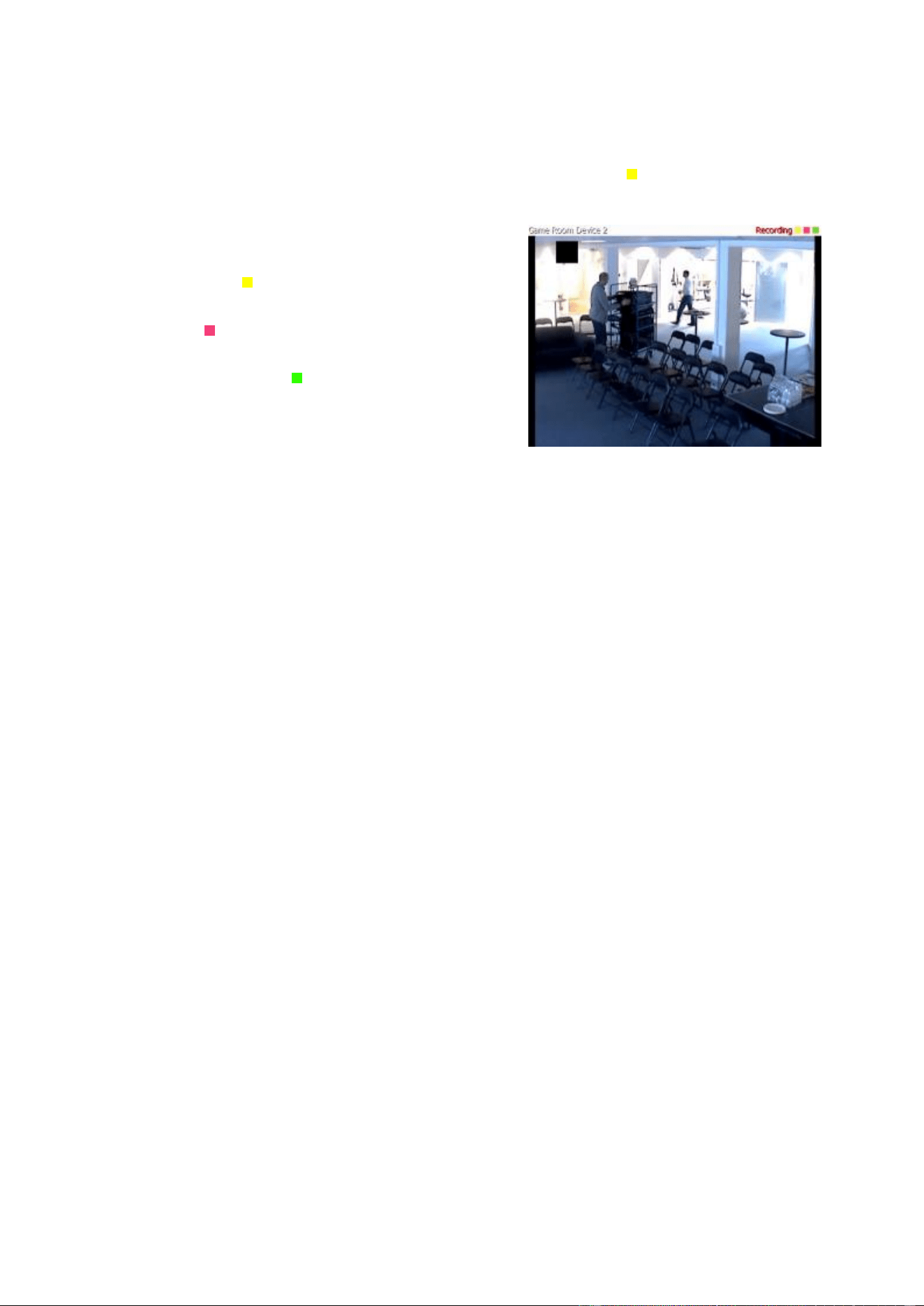
XProtect Professional VMS 2016 R3 - Administrator Manual
Advanced configuration
97
In XProtect Smart Client, event notification is given by a yellow indicator which lights up when a
relevant event has taken place. You can also add an optional sound on event notification in
XProtect Smart Client itself.
Three indicators are available for each camera in XProtect
Smart Client:
The yellow event indicator. Lights up when a
relevant event has taken place.
A red motion indicator. Lights up when motion
has been detected.
An optional green video indicator. Lights up
when video is received from the camera.
You can turn off the bar in which the indicators are
displayed in XProtect Smart Client. Do not turn off if
XProtect Smart Client must rely on event notifications.
Select required events
1. In the Available events list, select the relevant event. You can only select one event at a
time.
2. Click the >> button to copy the selected event to the Selected Events list.
3. Repeat for each required event.
If you later want to remove an event from the Selected Events list, select the relevant event, and
click the << button.
Output
When you configure video and recording (see "About video and recording configuration" on page
69) for specific cameras, you can also associate a camera with particular hardware output (see
"Add a hardware output" on page 110), for example the sounding of a siren or the switching on of
lights.
Associated output can then be activated automatically when motion is detected in video from the
camera, or manually when XProtect Smart Client users with the necessary rights (see "Configure
user and group rights" on page 161) view live video from the camera.
1. In the Available output list, select the required output. It is only possible to select one
output at a time. If you have not yet defined any suitable output, you can quickly do it:
Use the Configure Output button, located below the other fields.
2. Click the >> button to copy the selected output to the:
On manual activation list, in which case the output is available for manual activation
in XProtect Smart Client.
and/or
On motion detected list, in which case the output is activated when motion is
detected in video from the camera. If relevant, the same output can appear on both
lists.
3. Repeat for each required output.

XProtect Professional VMS 2016 R3 - Administrator Manual
Advanced configuration
98
If you later want to remove an output from the one of the lists, select the output in question, and
click the << button.
Motion detection & exclude regions
When you configure video and recording (see "About video and recording configuration" on page
69) for specific cameras, adjusting motion detection is important because it may determine when
video from the camera is recorded, when email notifications are generated or when hardware
output, such as lights or sirens, is activated. Time spent on finding the best possible motion
detection settings for each camera may help you later avoid unnecessary recordings and
notifications. Depending on the physical location of the camera, it may be a very good idea to test
motion detection under different physical conditions such as day/night or windy/calm weather.
Before you configure motion detection for a camera, you should configure the camera's video
properties (see "General" on page 89) including compression and resolution.
Cameras that do not support multiple simultaneous video streams cannot connect to the
surveillance server and the Management Application at the same time. Milestone recommends that
you stop (see "Start and stop services" on page 168) the Recording Server service when you
configure such devices for motion detection and PTZ.
See also View video from cameras in the Management Application (see "View video from cameras
in Management Application" on page 44).
Enable
Enable or disable (see "About motion detection" on page 69) the
built-in motion detection.
Show grid
Turn the grid on and off.
Turning the grid off may provide a less obscured view of the
preview image. You select the areas to exclude from motion
detection the same way as when the grid is visible. When the grid
is turned on, the preview image is divided into small sections by a
grid.
To define areas which should be excluded from motion detection,
drag the mouse over the areas in the preview image while
pressing the mouse button down. The left mouse button selects a
grid section and the right mouse button clears a grid section.
Selected areas are highlighted in blue.
Include All
Quickly select all grid sections in the preview image. This can be
useful if you want to exclude motion detection in most areas of
the image, in which case you can clear the few sections in which
you do not want to exclude motion detection.
Exclude All
Clear all grid sections in the preview image.

XProtect Professional VMS 2016 R3 - Administrator Manual
Advanced configuration
99
Manual sensitivity
Enable this functionality to adjust the Sensitivity slide for motion
yourself.
Drag the slider to the left for a higher sensitivity level, and to the
right for a lower sensitivity level.
The higher the sensitivity level, the less change is allowed in
each pixel before it is regarded as motion.
The lower the sensitivity level, the more change in each pixel
is allowed before it is regarded as motion.
Pixels in which motion is detected are highlighted in green in the
preview image.
Milestone recommends that you do not enable manual sensitivity
because:
With dynamic sensitivity, the system calculates and optimizes
the sensitivity level automatically and suppresses motion
detections that come from noise in the images.
Dynamic sensitivity improves motion detection at nighttime,
where the noise in the images often triggers false motion.
The system is not overloaded from too much recording.
The users are not missing results from insufficient recording.
Sensitivity
Use this setting to determine how much each pixel must change
before it is regarded as motion. With a high sensitivity, very little
change in a pixel is required before the system regards it as
motion. Areas in which motion is detected are highlighted in
green in the preview image.
Select a slider position in which only detections you consider
motion are highlighted. The more you drag the slider to the left,
the more of the preview image becomes highlighted. This is
because with a high sensitivity even the slightest change in a
pixel is regarded as motion.
As an alternative to using the slider, you may specify a value
between 0 and 256 in the field next to the slider to control the
sensitivity setting.
Motion
Adjust the Motion slider so that motion detection is only
triggered by the required level of motion. The selected motion
level is indicated by the black vertical line in the Level bar above
the sliders. The black vertical line serves as a threshold. When
motion is above (to the right of) the selected level, the bar
changes color from green to red, indicating a positive motion
detection.
Alternatively, specify a value between 0 and 10000 in the field on
the left to control the motion setting.
The more you drag the slider to the left, the more positive motion
detections you see because less change will be needed to trigger
a positive motion detection. The number of positive motion
detections may also affect the amount of video you record, the
amount of notifications you receive and more.

XProtect Professional VMS 2016 R3 - Administrator Manual
Advanced configuration
100
Keyframe Only
Select Keyframe only if you want motion detection to take place
only on keyframes of the video stream to reduce the system
resources used on motion detection.
Detection interval
Specify how often motion detection analysis is carried out on
video from the camera. The default is every 240 milliseconds
(close to once a quarter of a second). The interval is applied
regardless of your cameras' frame rate settings.
Adjusting this setting can help lower the amount of system
resources used on motion detection.
Detection resolution
Specify whether the full image or a selected percentage of the
image should be analyzed. For example, by specifying 25%,
every fourth pixel is analyzed instead of all pixels, reducing the
system resources used but also offering less accurate motion
detection.
Privacy masking
Set the following properties for privacy masking:
Enable
Enable the Privacy Masking feature.
Show grid
Turn the grid on or off. Turning the grid off may provide a less
obscured view of the preview image. Select areas to exclude the
same way as you would when the grid is visible.
When on, the preview image is divided into small sections by a
grid. To define areas which should be excluded from privacy
masking, drag the mouse over the areas in the preview image
while pressing the mouse button down. The left mouse button
selects a grid section and the right mouse button clears a grid
section. Selected areas are highlighted in red.
Show privacy mask
Turn the red area indicating privacy masking on or off. Turning
off the red area may provide a less obscured view of the preview
image.
Clear
Clear the privacy masking.
Fisheye lens (properties)
Fisheye lens technology allows you to view panoramic video through an advanced fisheye lens.
To use fisheye lens technology, you must enable the technology and, in some cases, enter a
special license key. If you are unsure if you need a special fisheye license key, contact your system
vendor for further information.
Enable fisheye lens support
Select the check box to enable use of the fisheye lens technology
and to be able to specify further properties.

XProtect Professional VMS 2016 R3 - Administrator Manual
Advanced configuration
101
Immervision Enables
®
panomorph RPL number
When you enable the panomorph support functionality, you must
also select a Registered Panomorph Lens (RPL) number from the
ImmerVision Enables
®
panomorph RPL number list to ensure
that the lens is correctly identified and configured with the lens
used with the camera. You can usually find the RPL number on
the lens itself or on the box it came in.
If you want to add additional types of lenses, go to File and
select Import new lens types. Locate the .xml file that
contains information about the lens type and press OK.
For details of ImmerVision, panomorph lenses, and RPLs, see the
ImmerVision Enables website
https://www.immervisionenables.com/.
Camera position/orientation
Choose whether the camera is mounted in the ceiling, on a wall
or on ground level.
PTZ preset positions
PTZ-related properties are only available when you are dealing with a pan-tilt-zoom (PTZ) camera.
You can use PTZ preset positions for making the PTZ camera automatically go to a particular
position when particular events occur, and when setting up PTZ patrolling profiles. Preset positions
can also be used in clients to allow users that have been given rights (see "Configure user and
group rights" on page 161) to move the PTZ camera between preset positions. Names of preset
positions must contain only the characters A-Z, a-z and the digits 0-9. If you import preset
positions from cameras, verify that their names do not contain other characters. If they do, change
the preset position names before you import them.
Cameras that do not support multiple simultaneous video streams cannot connect to the
surveillance server and the Management Application at the same time. Milestone recommends that
you stop (see "Start and stop services" on page 168) the Recording Server service when you
configure such devices for motion detection and PTZ.
See also View video from cameras in the Management Application (see "View video from cameras
in Management Application" on page 44).
PTZ type
Your configuration options depend on the type of PTZ camera in
question:
Type 1 (stored on server): You define preset positions by moving
the camera using the controls in the upper half of the window,
then storing each required position on the system server. You can
define up to 50 preset positions this way.
Type 2 (imported from camera): You import preset positions
which have previously been defined and stored on the PTZ
camera itself through the camera's own configuration interface.
The number of allowed preset positions depends on the PTZ
camera and driver used.
Type 3 (stored on camera): You define preset positions by
moving the camera with the controls in the upper half of the
window, then storing each required position in the camera's own
memory. You can define up to 50 preset positions this way. If
preset positions have already been defined for the camera, you
can simply import them for use with the system.

XProtect Professional VMS 2016 R3 - Administrator Manual
Advanced configuration
102
Import / Refresh
Only available when you have selected PTZ type 2 or 3. Lets you
import already defined preset positions from the camera's
memory for use with the system.
If you have already imported preset positions this way, and
preset positions have since then been added or changed on the
camera, you can use this button to refresh the imported preset
positions.
Add New
Only available when you have selected PTZ type 1. When you
have move the camera to a required position using the controls in
the upper half of the window, type a name for the position in the
blank field, then click the button to add the position to the list of
defined preset positions.
Remember that names of preset positions must contain only the
characters A-Z, a-z and the digits 0-9.
Set New Position
Only available when you have selected PTZ type 1 or 3. Lets you
change an already defined preset position. In the list, select the
preset position you want to change. Then move the camera to the
new required position using the controls in the upper half of the
window. Then click the button to overwrite the old position with
the new one.
Delete
Only available when you have selected PTZ type 1 or 3. Lets you
delete an already defined preset. In the list, select the preset
position you want to delete, then click the button.
Before you delete a preset position, make sure it is not used in
PTZ patrolling or PTZ on event. Since the preset positions are
stored on the camera, you can bring a deleted preset position
back into your system by clicking the Import / refresh button.
If you bring back a preset position this way, and you use the
preset position with PTZ patrolling or PTZ on event, you must
manually configure the PTZ patrolling and/or PTZ on event to use
the preset position again.
Test
Try out a preset position. In the list, select the preset position
you want to test, then click the button to view the camera move
to the selected position.
PTZ control wheel
Move a preset position selected in the list up and down
respectively. The selected preset position is moved one step per
click. By moving preset positions up or down, you can control the
sequence in which preset positions are presented in clients.
PTZ patrolling (properties)
Cameras that do not support multiple simultaneous video streams cannot connect to the
surveillance server and the Management Application at the same time. Milestone recommends that
you stop (see "Start and stop services" on page 168) the Recording Server service when you
configure such devices for motion detection and PTZ.
See also View video from cameras in the Management Application (see "View video from cameras
in Management Application" on page 44).
Available functionality depends on the system you are using. See the Product comparison chart (on
page 11) for more information.

XProtect Professional VMS 2016 R3 - Administrator Manual
Advanced configuration
103
You can only set PTZ-related properties for pan-tilt-zoom (PTZ) cameras. PTZ patrolling is the
continuous movement of a PTZ camera between a number of preset positions. To use patrolling,
you must specify at least two preset positions for the relevant PTZ camera. To configure PTZ
patrolling, select a patrolling profile in the Patrolling profiles list and specify relevant properties
to define the exact behavior of the patrolling profile. When you have defined your patrolling
profiles, remember to schedule the use of patrolling profiles. Note that if users manually operate
PTZ cameras, this can override patrolling. You can specify a patrolling profile with only one preset if
needed. Such a patrolling profile can be useful in two cases: for moving a PTZ camera to a specific
position at a specific time, and for moving a PTZ camera to a specific position upon manual control
of the PTZ camera.
Patrolling profiles
A PTZ camera may patrol according to several different patrolling profiles. For example, a PTZ
camera in a supermarket may patrol according to one patrolling profile during opening hours, and
according to another patrolling profile when the supermarket is closed. You can reuse the names of
patrolling profiles defined for other cameras. This allows you to use a single patrolling profile name
across several PTZ cameras, and can make scheduling of PTZ patrolling much easier. Even though
several PTZ cameras share a patrolling profile name, the movement between preset positions is
individual for each camera.
From the Patrolling profiles list, select which patrolling profile to configure:
Add New
Add a new patrolling profile to the list. When you add a new
patrolling profile, you can either give it a unique name, or reuse
an existing name from another PTZ camera with PTZ patrolling.
Using several identically named patrolling profiles can be
advantageous when you later configure scheduling. Example: If
you have configured patrolling profiles identically named Night
Patrolling on 25 different cameras, you can schedule the use of
Night Patrolling on all 25 cameras in one go, even though Night
Patrolling covers individual preset positions on each of the 25
cameras.
Delete
Delete an existing patrolling profile. Note that the selected
patrolling profile is removed from the list without further warning.
Patrolling list
Having selected a patrolling profile in the Patrolling profiles list, you can specify which of the PTZ
camera's preset positions to use with the selected patrolling scheme. Use the button to copy a
selected preset positions to the Patrolling list. To change the sequence of preset positions in the
Preset Positions list, select a preset position, and use the or buttons to move the selected
preset position up or down in the list. The selected preset position is moved one step per click. If
you later want to remove a preset position from the Patrolling list, select the preset position in
question, and click the button.
Wait time (sec.)
Specify the number of seconds for which the PTZ camera should
stay at each preset position before it moves on to the next preset
position. The default is 10 seconds. The wait time applies to all
presets in the patrolling profile. The PTZ camera stays at each
preset position for the same number of seconds.

XProtect Professional VMS 2016 R3 - Administrator Manual
Advanced configuration
104
Transition time (sec.)
Specify the number of seconds needed for the PTZ camera to
move from one preset position to another. The default is five
seconds. During this transition time, motion detection is
automatically disabled, as irrelevant motion is otherwise likely to
be detected while the camera moves between the preset
positions. After the specified number of seconds, motion detection
is automatically enabled again.
The transition time applies to all presets in the patrolling profile.
It is important that the camera can switch between any of the
patrolling profile's preset positions within the number of seconds
you specify. If not, the system is likely to detect false motion.
Note that it takes longer for the PTZ camera to move between
positions that are located physically far apart (for example from
an extreme left position to an extreme right position) than
between positions that are located physically close together.
PTZ scanning
PTZ scanning (continuous panning) is supported on a few PTZ cameras only. You can enable PTZ
scanning and select a PTZ scanning speed from the list below the check box. PTZ scanning only
works for PTZ type 1 cameras (where preset positions are configured and stored on the server). If
the camera is a PTZ type 2 camera, and you import preset positions which have previously been
defined and stored on the PTZ camera itself through the camera's own configuration interface, PTZ
scanning stops working.
Pause PTZ patrolling
PTZ patrolling pauses automatically when users operate the camera manually as well if your
system is using PTZ on Event. If the system detects motion, it may also pause PTZ patrolling.
Pause settings are tied to the selected patrolling profile. This allows you the flexibility of having
different pause settings for different patrolling profiles on the same camera.
Pause patrolling if motion is detected
To pause PTZ patrolling when the system detects motion, so that the PTZ camera remains at the
position where the system detected motion for a specified period of time, do the following:
1. Select the Pause patrolling if motion is detected check box.
2. Select whether the PTZ camera should resume patrolling:
After a certain number of seconds has passed since first detection of motion, regardless
whether further motion is detected
or
After a certain number of seconds has passed without further detection of motion
3. Specify the number of seconds for the selected option (default is ten and five seconds
respectively).
4. Unless the transition time is set to zero, the system automatically disables motion detection
while the camera moves between preset positions, as the system is likely to detect
irrelevant motion otherwise while the camera moves between the preset positions.

XProtect Professional VMS 2016 R3 - Administrator Manual
Advanced configuration
105
Resume PTZ patrolling
The system automatically pauses PTZ patrolling when users operate the camera manually as well
as if PTZ on Event is in use. You can specify how many seconds should pass before the system
resumes regular patrolling after a manual or event-based interruption. The default is 30 seconds.
Apart from manual control, users of XProtect Smart Client can also stop a selected PTZ camera's
patrolling entirely. For XProtect Smart Client users, the number of seconds specified in the
Patrolling settings section therefore only applies when users manually control a PTZ camera and
not when users stop a PTZ camera's patrolling entirely. When XProtect Smart Client users stop a
PTZ camera's patrolling entirely, the camera's patrolling resumes only when the XProtect Smart
Client user selects to resume it.
PTZ on event
PTZ-related properties are only available when you are dealing with a pan-tilt-zoom (PTZ) camera.
When a PTZ camera supports preset positions (see "PTZ preset positions" on page 101), you can
make the PTZ camera automatically go to a particular preset position when a particular event
occurs (see "Overview of events and output" on page 108). When associating events with preset
positions on a PTZ camera, you can select between all events defined on your system. You are not
limited to selecting events defined on a particular hardware device.
Component
Requirement
Event
Select the relevant event.
PTZ Preset Position
Select the relevant preset position. For this purpose, you can only
use an event once per PTZ camera. However, use different events
for making the PTZ camera go to the same preset position.
Example:
Event 1 makes the PTZ camera go to preset position A
Event 2 makes the PTZ camera go to preset position B
Event 3 makes the PTZ camera go to preset position A
If later you want to end the association between a particular event and a particular preset position,
clear the field containing the event. After you have made the PTZ setting changes, restart services
(see "Start and stop services" on page 168).
Cameras that do not support multiple simultaneous video streams cannot connect to the
surveillance server and the Management Application at the same time. Milestone recommends that
you stop (see "Start and stop services" on page 168) the Recording Server service when you
configure such devices for motion detection and PTZ.
See also View video from cameras in the Management Application (see "View video from cameras
in Management Application" on page 44).

XProtect Professional VMS 2016 R3 - Administrator Manual
Advanced configuration
106
Microphones
About microphones
In your system, Microphones are typically attached to hardware devices, and therefore physically
located next to cameras. Operators, with the necessary rights, can listen to recordings through
XProtect Smart Client if the computer running XProtect Smart Client has speakers attached. You
manage microphones on your system, meaning you can always manage the microphones attached
to cameras, not microphones attached to XProtect Smart Client operators' computers.
If you have added more microphones to your system than you need, you can hide the ones you do
not need by right-clicking the relevant microphone or speaker and select Hide. If you need the
hidden microphone again, you can right-click the overall microphone icon and select Show Hidden
Items.
Configure microphones or speakers
Available functionality depends on the system you are using. See the Product comparison chart (on
page 11) for more information.
1. Expand Advanced Configuration > Hardware Devices, and expand the hardware
device to which the relevant microphone or speaker is attached.
2. Right-click the relevant microphone or speaker, and select Properties.
3. Specify properties (see "Speaker properties" on page 66) as required.
Configuration of microphones and speakers in your system is very basic. You control volume
settings and similar settings on the microphone or speaker units themselves.
Show or hide microphones or speakers
If you have added more microphones or speakers to your system than you need, you can hide the
ones you do not need by right-clicking the relevant microphone or speaker and select Hide. If you
need the hidden microphone/speaker again, you can right-click the overall microphone or speaker
icon and select Show Hidden Items.
Microphone (properties)
When you configure video and recording (see "About video and recording configuration" on page
69) for specific cameras, you can determine when to record audio. Your choice applies for all
cameras on your system.
Microphone properties
Enabled
Microphones are by default enabled, meaning that they can
transfer audio to your system. If needed, you can disable an
individual microphone, in which case no audio is transferred from
the microphone to your system.

XProtect Professional VMS 2016 R3 - Administrator Manual
Advanced configuration
107
Name
The name as it appears in the Management Application as well as
in clients. You can overwrite the existing name with a new one.
Names must be unique, and must not contain any of these special
characters: < > & ' " \ / : * ? | [ ]
On some hardware devices, you can also enable/disable audio on the hardware device itself,
typically through the hardware device's own configuration web page. If audio on a hardware device
does not work after enabling it in the Management Application, you should verify if the problem
exists because audio is disabled on the hardware device itself.
Recording settings
Always
Always record audio on all applicable cameras.
Follow video
Recording audio only when video is recorded from a camera that
has a microphone attached.
Never
Never record audio on any cameras. Note that even though the
system never records audio, you can still listen to live audio in
XProtect Smart Client.
Events and output
About input and output
Hardware input, such as door sensors, can be attached to input ports on hardware devices. Input
from such external hardware input units can be used for generating events in your system.
Hardware output units can be attached to output ports on many hardware devices, allowing you
to activate lights, sirens, and more from your system. Such hardware output can be activated
automatically by events, or manually from clients.
Before you specify use of hardware input and hardware output units on a hardware device, verify
the hardware device recognized the sensor operation. Most hardware devices are capable of
showing this in their configuration interfaces, or via CGI script commands. Also check the system's
release notes to verify that the hardware device and firmware used supports input and output-
controlled operations.
You do not have to configure hardware input units separately. Any hardware input units connected
to hardware devices are automatically detected when you add the hardware devices to your
system. The same goes for hardware output, but hardware output does require some simple
configuration in your system.
If you want to configure hardware output and automatically trigger output when events
occur, so that, for example, lights are switched on when a door is opened or when motion is
detected in video, see Add a hardware output (on page 110) and Configure hardware output on
event (on page 112).
About events and output
Available functionality depends on the system you are using. See the Product comparison chart (on
page 11) for more information.

XProtect Professional VMS 2016 R3 - Administrator Manual
Advanced configuration
108
You can use events and output of various types to automatically trigger actions in your system.
Examples of actions: starting or stopping recording on cameras, switching to a particular video
frame rate, triggering notifications, making PTZ cameras move to specific preset positions. You can
also use events for activating hardware output. You can also configure events and output to
generate alarms.
Events can be divided in to:
Internal events (system-related): for example, motion, server responding/not
responding, archiving problems and lack of disk space.
External events (integrated): for example, MIP plug-in events.
Overview of events and output
Available functionality depends on the system you are using. See the Product comparison chart (on
page 11) for more information.
Types of events:
Name
Description
Analytics events:
You can use analytics events as alarms and integrate seamlessly
with the Alarms feature.
Analytics events are typically data received from external third-
party video content analysis (VCA) providers. An example of a
VCA-based system could be an access control system.
Hardware input events:
Hardware input, such as door sensors, can be attached to input
ports on hardware devices. Input from such external hardware
input units can be used for generating events in the system.
Events based on input from hardware input units attached to
hardware devices are called hardware input events.
Some hardware devices have their own capabilities for detecting
motion, for detecting moving and/or static objects and more
(configured in the hardware devices' own software, typically by
accessing a browser-based configuration interface on the
hardware device's IP address.) When this is the case, your
system considers such detections as input from the hardware,
and you can use such detections as input events as well.
Lastly, hardware input events can be based on the system
detecting motion in video from a camera, based on motion
detection settings in the system.
This type of hardware input events is also called system motion
detection events or VMD (Video Motion Detection) events. In
earlier versions of the surveillance system, VMD events were an
event type of their own. They are now considered a type of
hardware input event.
Hardware output:
Hardware output units can be attached to output ports on many
hardware devices, allowing you to activate lights, sirens, and
more from the system. Such hardware output can be activated
automatically by events, or manually from clients.

XProtect Professional VMS 2016 R3 - Administrator Manual
Advanced configuration
109
Name
Description
Manual events:
Events may be generated manually by the users selecting them
in their clients. These events are called manual events.
Manual events can be of the type Global events or Timer
events:
Global events apply to all hardware whereas timer events are
separate events, triggered by the hardware input event, manual
event or generic event under which they are defined. Timer
events occur a specified number of seconds or minutes after the
event, under which they are defined, has occurred. Timer events
may be used for a wide variety of purposes, typically for stopping
previously triggered actions.
Example:
A camera starts recording based on a hardware input event, for
example when a door is opened. A timer event stops the
recording after 15 seconds.
Generic events:
Input may also be received in the form of TCP or UDP data
packages, which the system can analyze, and—if they match
specified criteria—use to generate events. Such events are called
generic events.
Output control on event:
Hardware output can be activated automatically when events
occur. For example, when a door is opened (hardware input
event), lights are switched on (hardware output).
When you configure the output control, you can select between
all output and events defined in the system. You are not limited
to selecting output or events defined on particular hardware
devices. You can use a single event for activating more than one
output.
Before you configure events of any type, configure general event handling, such as which ports
the system should use for event data. Normally, you can just use the default values, but it is a
good idea to verify that your organization is not already using the ports for other purposes. See
Configure general event handling (on page 113).
Before you specify use of hardware input and hardware output units on a hardware device, verify
that sensor operation is recognized by the hardware device. Most hardware devices are capable of
showing this in their configuration interfaces, or via CGI script commands. Also check the
surveillance system's release notes to verify that input and output controlled operations are
supported for the hardware device and firmware used. If you are using several servers in a
master/slave setup, input and output on a specific hardware device should be defined on one of the
servers only. Do not define the same input or output on the same hardware device on several
servers.
You do not have to configure hardware input units separately. Any hardware input units connected
to hardware devices are automatically detected when you add the hardware devices to the system.
The same goes for hardware output, but hardware output does require some simple configuration
in the system.
If you want to configure hardware output and automatically trigger output when events
occur, so that, for example, lights are switched on when a door is opened or when motion is
detected in video, see Add a hardware output (on page 110) and Configure hardware output on
event (on page 112).

XProtect Professional VMS 2016 R3 - Administrator Manual
Advanced configuration
110
When you are ready to configure events, see Add a hardware input event (on page 110), Add a
generic event (on page 112), and Add a manual event (on page 111). If you want to use timer
events with your other events, see Add a timer event (on page 112).
Add an analytics event
To add an analytics event, do the following:
1. Expand Events and Output, right-click Analytics Events and select Create New.
2. Specify required properties. Click OK.
3. Save your configuration changes by clicking Save in the yellow notification bar in the
upper-right corner of the Management Application.
Add a hardware input event
With hardware input events, you can turn input received from input units attached to hardware
devices into events (see "Overview of events and output" on page 108) in your system.
Before you specify input for a hardware device, verify the hardware device recognizes sensor
operation. Most hardware devices can show this in their configuration interfaces, or via CGI script
commands. Also check the release notes to verify that input-controlled operation is supported for
the hardware device and firmware used.
To add and/or configure a hardware input event, do the following:
1. Expand Advanced Configuration > Events and Output. Right-click Hardware Input
Events > Enable New Input Event.
2. In the Hardware Input Event Properties window's list of hardware devices, expand the
relevant hardware device to see a list of pre-defined hardware input.
3. Select the required types of input to use them as events. The types of input often vary from
camera to camera. If motion detection (see "Motion detection & exclude regions" on page
98) is enabled in the system for the relevant camera, note the input type System Motion
Detection, which lets you turn detected motion in the camera's video stream into an
event.
Note that some types of input are mutually exclusive. When you select one type of input,
you may therefore note that other types of input become unavailable for selection.
4. For each selected type of input, select required properties (see "Hardware input event" on
page 118). When ready, click OK, or click the Add button to add a timer event (on page
112) to the event you have just created.
5. Save your configuration changes by clicking Save in the yellow notification bar in the
upper-right corner of the Management Application.
Add a hardware output
With hardware output, you can add external output units, such as lights, sirens and door openers,
to your system. Once added, output can be activated automatically by events (see "Overview of
events and output" on page 108) or detected motion, or manually by client users.
Before you specify output, verify that sensor operation is recognized by the hardware device with
which you are going to use the output. Most hardware devices are capable of showing this in their

XProtect Professional VMS 2016 R3 - Administrator Manual
Advanced configuration
111
configuration interfaces, or via CGI script commands. Also check the release notes to verify that
output-controlled operation is supported for the hardware device and firmware used.
To add a hardware output event, do the following:
1. Expand Advanced Configuration > Events and Output. Right-click Hardware Output
> Add New Output.
2. In the Hardware Output Properties window's list of hardware devices, select the relevant
hardware device, and click the Add button below the list.
3. Specify required properties (see "Hardware input event" on page 118).
4. Click OK.
5. Save your configuration changes by clicking Save in the yellow notification bar in the
upper-right corner of the Management Application.
For information about how to configure automatic activation of hardware output when events
occur, see Configure hardware output on event (on page 112). You configure output for manual
activation in clients as well as for automatic activation on detected motion individually for each
camera (see "Output" on page 97).
Add a manual event
With manual events, your users with required rights (see "Configure user and group rights" on
page 161) can trigger events manually from their clients. Manual events can be global (shared by
all cameras) or tied to a particular camera (only available when the camera is selected). You can
use manual events for a wide variety of purposes, for example:
As start and stop events for use when scheduling cameras' online periods (see "Online
period" on page 133). For example, you can make a camera start or stop transferring video
to the surveillance system based on a manual event.
As start and stop events for controlling other camera settings. For example, you can make
a camera use a higher frame rate based on a manual event or you can use a manual event
for triggering PTZ on event (on page 105).
For triggering output. Particular output can be associated (see "Configure hardware output
on event" on page 112) with manual events.
For triggering event-based notifications (see "About notifications" on page 141).
In combinations. For example, a manual event could make a camera start transferring
video to the surveillance system while an output is triggered and an e-mail notification is
sent to relevant people.
To add a manual event, do the following:
1. Expand Advanced Configuration > Events and Output. Right-click Manual Events >
Add New Manual Event
2. In the list in the left side of the Manual Event Properties, select global or a camera as
required.
3. Click the add button and specify required properties (see "Hardware input event" on page
118). When ready, click OK, or click the Add button again to add a timer event (on page
112) to the event you have just created.
4. Save your configuration changes by clicking Save in the yellow notification bar in the
upper-right corner of the Management Application.

XProtect Professional VMS 2016 R3 - Administrator Manual
Advanced configuration
112
Add a generic event
Available functionality depends on the system you are using. See the Product comparison chart (on
page 11) for more information.
Your system can analyze received TCP and/or UDP data packages, and automatically trigger events
(see "Overview of events and output" on page 108) when specified criteria are met. This way, you
can easily integrate your surveillance system with a range of external sources, for example access
control systems and alarm systems.
1. Expand Advanced Configuration, then expand Events and Output. Right-click Generic
Events > Properties.
2. In the Generic Event Properties window, click the Add button, and specify the relevant
properties. For more information, see Generic event (Events and Output-specific
properties)_not in ES (see "Generic event" on page 121).
3. To add a timer event to the generic event, click the Add button.
4. Save your configuration changes by clicking Save in the yellow notification bar in the
upper-right corner of the Management Application.
Add a timer event
Timer events are separate events (see "Overview of events and output" on page 108), triggered by
the type of event under which they are defined. Timer events occur a specified number of seconds
or minutes after the event under which they are defined has occurred. Timer events may be used
for a wide variety of purposes, typically for stopping previously triggered actions. Examples:
A camera starts recording based on a hardware input event, for example when a door is
opened. A timer event stops the recording after 15 seconds
Lights are switched on and a camera starts recording based on a manual event. A timer
event stops the recording after one minute, and another timer event switches the lights off
after two minutes
To add a timer event, select any event you have previously configured, click the Add button, and
specify required properties (see "Timer event" on page 120). Your system comes with two simple
schedule profiles, Always on and Always off, which you cannot edit or delete. If these do not
meet your needs, you can create any number of customized schedule profiles for each camera. You
can reuse a customized schedule profile for more than one purpose if you want to. Save your
configuration changes by clicking Save in the yellow notification bar in the upper-right corner of
the Management Application.
Tip: You can add as many timer events as required under an event. This way, you can, for
example, make one timer event trigger something 10 seconds after the main event, another timer
event trigger something else 30 seconds after the main event, and a third timer event trigger
something else 2 minutes after the main event.
Configure hardware output on event
Once you have added hardware output (see "Add a hardware output" on page 110), such as lights,
sirens, door openers and more, you can associate the hardware output with events (see "Overview
of events and output" on page 108). This way, particular hardware output can be activated
automatically when events occur. Example: When a door is opened (hardware input event), lights
are switched on (hardware output).

XProtect Professional VMS 2016 R3 - Administrator Manual
Advanced configuration
113
When making the associations, you can select between all output and events defined on your
surveillance system server. You are not limited to selecting output or events defined on particular
hardware devices.
1. Expand Advanced Configuration, then expand Events and Output. Right-click Output
Control on Event and select Properties.
2. Fill in the relevant properties (see "Output control on event (Events and Output-specific
properties)" on page 124). Click OK.
3. Save your configuration changes by clicking Save in the yellow notification bar in the
upper-right corner of the Management Application.
You can use a single event for activating more than one output. You cannot delete associations, but
you can change your selections or select None in both columns as required.
Note: If you have not yet defined any suitable event or output, you can quickly do it: Use the
Configure events list and/or Configure Output... button, located below the list of associations.
Configure general event handling
Before configuring events of any type, configure general event handling, such as which ports your
system should use for event data. Normally, you can just use the default values, but it is a good
idea to verify that your organization is not already using the ports for other purposes.
1. Expand Advanced Configuration, right-click Events and Output, and select Properties.
2. Specify required properties (see "Ports and polling" on page 115). Your system comes with
two simple schedule profiles, Always on and Always off, which you cannot edit or delete.
If these do not meet your needs, you can create any number of customized schedule
profiles for each camera. You can reuse a customized schedule profile for more than one
purpose if you want to.
3. Save your configuration changes by clicking Save in the yellow notification bar in the
upper-right corner of the Management Application.
Generate alarms based on analytics events
Available functionality depends on the system you are using. See the Product comparison chart (on
page 11) for more information.
Generating alarms based on analytics events is normally a three-step process:
1. Enable the analytics events feature and set up its security. A list of allowed addresses can
be used to control who can send event data to the system and on which port the server
listens.
2. Create the analytics event, possibly with a description of the event, and test it.
3. Use the analytics event as the source of an alarm definition (see "Alarms definition" on
page 240).
As mentioned, a third-party VCA is most often required for supplying data to your system. Which
VCA tool to use is entirely up to you, as long as the data supplied by the tool adheres to the
applied formatting rules described in the Milestone Analytics Events Developers Manual. For more
information, contact Milestone.

XProtect Professional VMS 2016 R3 - Administrator Manual
Advanced configuration
114
Test a generic event
If you have added a generic event, a quick and easy way to test your generic event is to first set
up an event notification and then use Telnet to send a small amount of data that triggers the
generic event and the event notification.
Telnet is installed by default on older versions of Windows. For more information, see
https://technet.microsoft.com/en-us/library/cc771275(v=ws.10).aspx
https://technet.microsoft.com/en-us/library/cc771275(v=ws.10).aspx.
For this example, we have created a generic event called Video. The generic event specifies that if
the term video appears in a received TCP data package, this should trigger the generic event. Your
generic event may be different, but you can still use these principles:
1. Expand Advanced Configurations, then expand Cameras and Storage Information,
right-click a camera that you have access to in XProtect Smart Client, and select
Properties.
2. Select Event Notification and then the required generic event. Make sure that your
generic event is the only event appearing in the Selected Events list while you are
performing the test, otherwise you cannot be sure that it is your generic event that triggers
the event notification. Once you are done testing, you can move any temporarily removed
events back to the Selected Events list.
3. Save your configuration changes by clicking the Save Configuration button in the
Management Application toolbar.
4. Make sure the Recording Server service is running. Also make sure that the camera that
you configured the event notification for is displayed and that you have camera title bars
enabled in XProtect Smart Client, so you can see the yellow event indicator.
5. Run Telnet and type the following in the
6. In Windows' Start menu, select Run, and type the following in the Open field:
If you are performing the test on the system server itself: telnet localhost 1234
If you are performing the test from a remote computer: Substitute localhost with the
IP address of your system's server. Example: If the IP address of the surveillance
system server is 123.123.123.123, type: telnet 123.123.123.123 1234
This opens a Telnet window.
In the above examples, the number 1234 indicates the port on which the system server
listens for generic events. Port 1234 is the default port for this purpose, but you can change
this by specifying another port number as part of the general event handling configuration
(see "Configure general event handling" on page 113). If you have changed the alert and
generic event port number on your system, type your system's alert and generic event port
number instead of 1234.
7. In the Telnet window, type the terms (event substring) required to trigger your generic
event. In our case, a single term, video, is required:
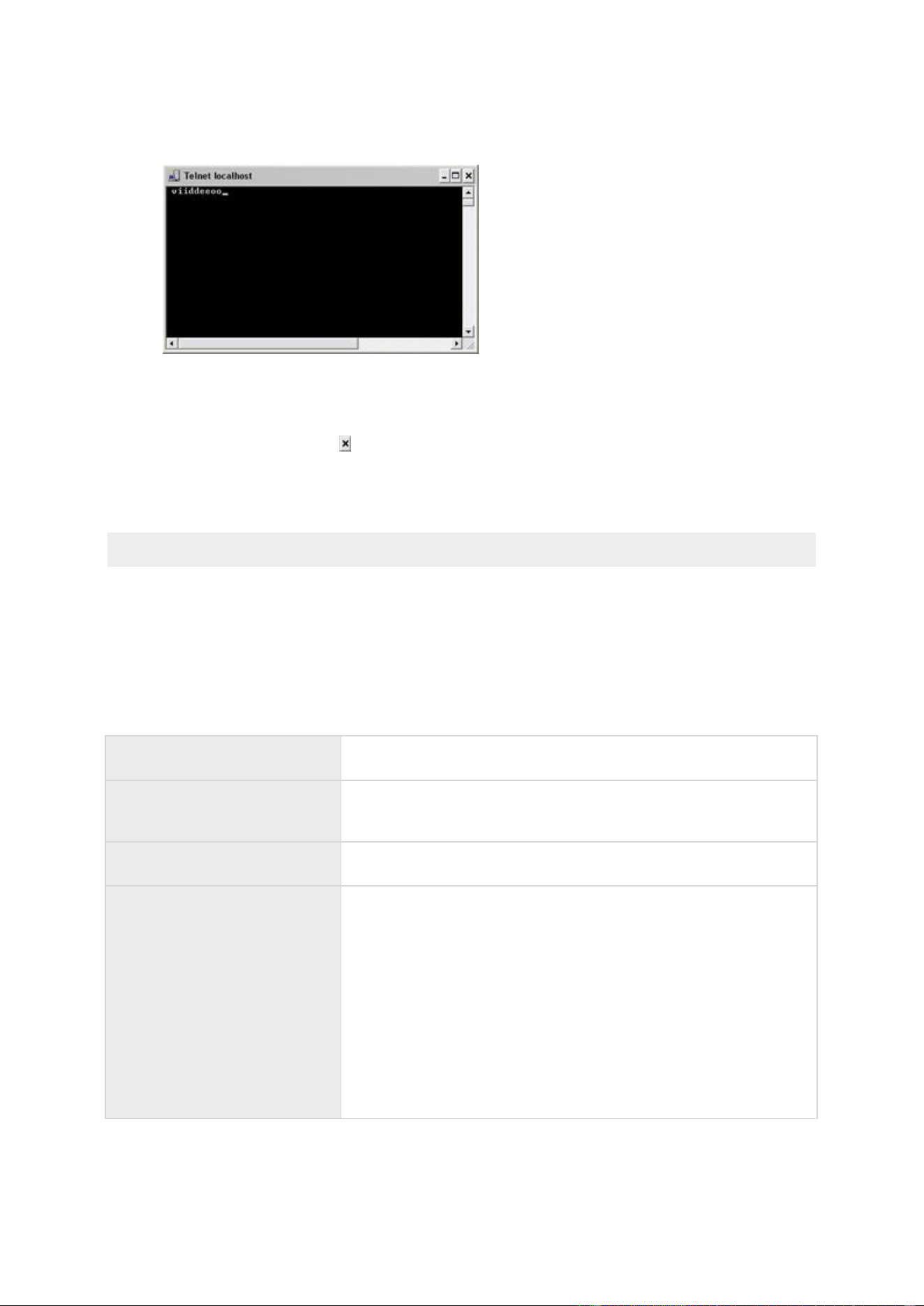
XProtect Professional VMS 2016 R3 - Administrator Manual
Advanced configuration
115
While you type in the Telnet window, you may experience an echo. This is the server
repeating some or all of the characters it receives. It does not have any impact as long as
you are sure you type the relevant characters.
8. Close the Telnet window . You must close the window, since your input is not sent to the
surveillance system until you close the window.
9. Go to XProtect Smart Client. If the yellow event indicator lights up for the relevant camera,
your generic event works as intended.
Important: You can enter up to 128 characters for your generic event. The system disregards any
extra characters you may enter once you have passed 128 characters.
General event properties
Ports and polling
In the General Event Properties window you can specify network settings to be used in
connection with event handling.
Alert and generic event port
Specify port number to use for handling events. Default port is
port 1234.
SMTP event port
Specify the port number to use for sending event information
from hardware devices to the system via SMTP. The default port
is port 25.
FTP event port
The port to use for FTP communication with the hardware device.
The default port is port 21.
Polling interval [1/10]
second
For a small number of hardware devices, primarily dedicated
input/output devices (see "About dedicated input/output devices"
on page 63), the system must regularly check the state of the
hardware devices' input ports in order to detect input. Such state
checking at regular intervals is called polling.
You can specify (in tenths of a second) the interval between state
checks. Default value is 10 tenths of a second (that is one
second). For dedicated input/output devices, it is highly
recommended that the polling frequency is set to the lowest
possible value (one tenth of a second between state checks).
For information about which hardware devices require polling, see
the release notes.
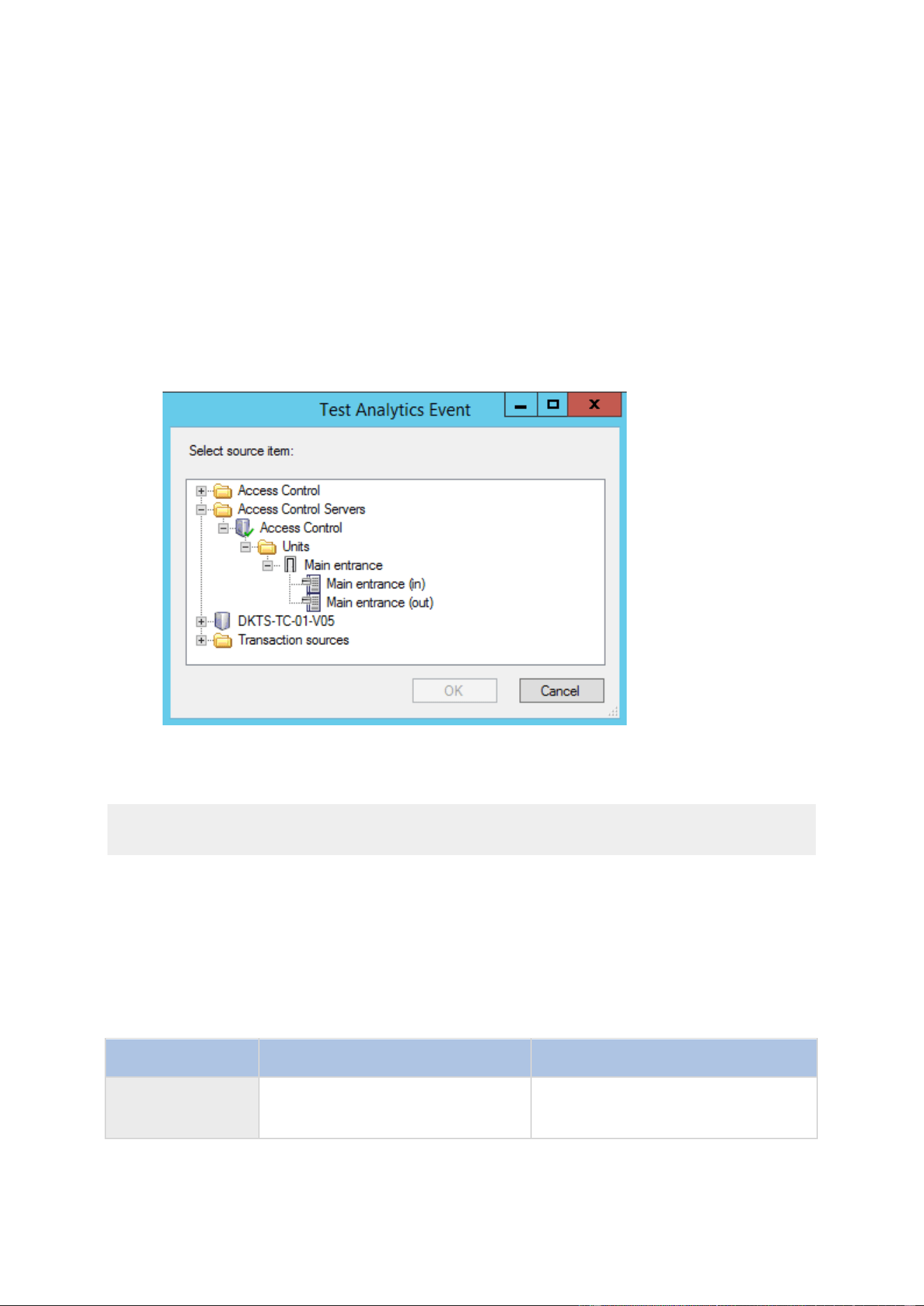
XProtect Professional VMS 2016 R3 - Administrator Manual
Advanced configuration
116
Events and output properties
Test an analytics event
After you create an analytics event, you can test the requirements (see "Test Analytics Event
(properties)" on page 116), for example that the analytics events feature has been enabled in
Management Application.
1. Select an existing analytics event.
2. In the properties, click the Test Event button. A window appears that shows all the
possible sources of events.
3. Select the source of your test event, for example a camera. The window is closed and a
new window appears that goes through four conditions that must be fulfilled for the
analytics event to work.
As an additional test, in XProtect Smart Client you can verify that the analytics event was sent to
the event server. To do this, open XProtect Smart Client and view the event in the Alarm
Manager tab.
See also
About analytics events
Test Analytics Event (properties)
When you test the requirements of an analytics event, a window appears that checks four
conditions and provides possible error descriptions and solutions.
Condition
Description
Error messages and solutions
Changes saved
If the event is new, is it saved? Or if
there are changes to the event
name, are these changes saved?
Save changes before testing
analytics event.
Solution/Explanation: Save changes.

XProtect Professional VMS 2016 R3 - Administrator Manual
Advanced configuration
117
Condition
Description
Error messages and solutions
Analytics Events
enabled
Is the Analytics Event feature
enabled?
Analytics events have not been
enabled. Solution/Explanation: Enable
the Analytics Events feature. To do
this, click Tools > Options >
Analytics Events and select the
Enabled check box.
Address allowed
Is the IP address/host name of the
machine sending the event(s)
allowed (listed on the analytics
events address list)?
The local host name must be
added as allowed address for the
Analytics Event service.
Solution/Explanation: Add your
machine to the analytics events
address list of allowed IP addresses or
host names.
Error resolving the local host
name. Solution/Explanation: The IP
address or host name of the machine
cannot be found or is invalid.
Send analytics
event
Did sending a test event to the
Event Server succeed?
See table below.
Each step is marked by either failed: or successful: .
Error messages and solutions for the condition Send analytics event:
Event server not found
Unable to find the event server on the list of registered services.
Error connecting to event
server
Unable to connect to the event server on the stated port. The
error occurs most likely because of network problems, or the
event server service has stopped.
Error sending analytics
event
The connection to the event server is established, but the event
cannot be sent. The error most likely occurs because of network
problems, for example a time out.
Error receiving response
from event server
The event has been sent to the event server, but no reply
received. The error most likely occurs because of network
problems or a port that is busy.
See the event server log, typically located at
ProgramData\Milestone\XProtect Event Server\logs\.
Analytics event unknown by
event server
The event server service does not know the event. The error
most likely occurs because the event or changes to the event
have not been saved.
Invalid analytics event
received by event server
The event format is incorrect.
Sender unauthorized by
event server
Most likely your machine is not on the list of allowed IP addresses
or hostnames.
Internal error in event
server.
Event server error.
See the event server log, typically located at
ProgramData\Milestone\XProtect Event Server\logs\.

XProtect Professional VMS 2016 R3 - Administrator Manual
Advanced configuration
118
Invalid response received
from Event server
The response is invalid. Possibly the port is busy or there are
network problems.
See the event server log, typically located at
ProgramData\Milestone\XProtect Event Server\logs\.
Unknown response from
event server
The response is valid, but not understood. The error occurs
possibly because of network problems, or the port is busy.
See the event server log, typically located at
ProgramData\Milestone\XProtect Event Server\logs\.
Unexpected error
Please contact Milestone support for help.
Hardware input event
Available functionality depends on the system you are using. See the Product comparison chart (on
page 11) for more information.
When you add hardware input events (see "Add a hardware input event" on page 110), properties
may depend on the selected type of input:
Enable
Select the check box to use selected type of input as an event in
the system, and specify further properties.
Event name
Specify a name. Names must be unique, and must not contain
any of these special characters: < > & ' " \ / : * ? | [ ]
Some cameras only support event names of a certain length
and/or with a certain structure. Refer to the camera's
documentation for exact details.
Images from camera
Only relevant if you use pre- and post-alarm images in your
system. This functionality is only available for selected cameras
and enables the sending of images from immediately before an
event took place from the camera to the surveillance system via
email.
Note pre- and post-alarm images are not the same as the pre-
and post-recording feature (see "Recording" on page 93)
particular to your system.
Number of pre-alarm
images
Specify the relevant number of pre-alarm images. The allowed
number of images may differ from camera to camera. The
allowed range is shown to the right of the field.
This is only relevant if you are using pre-alarm images which is a
feature that is available for selected cameras only.
Frames per second
Only relevant if using pre-alarm images, a feature available for
selected cameras only. Specify required frame rate. Used in
combination with the Number of pre-alarm images field, this field
indirectly allows you to control how long before the event you
want to receive pre-alarm images from.

XProtect Professional VMS 2016 R3 - Administrator Manual
Advanced configuration
119
Send e-mail if this event
occurs
Only available if email notifications (see "Configure email
notifications" on page 142) are enabled. Select if the system
should automatically send an email when the event occurs.
Recipients are defined as part of the email notification
configuration. When using email notifications, remember the
individual cameras' scheduling.
Attach image from camera
Only available if e-mail notification (see "Configure email
notifications" on page 142) is enabled. Select to include an
image, recorded at the time the event is triggered, in the e-mail
notification, then select the relevant camera in the list next to the
check box.
Delete
Delete a selected event.
Add
When a specific hardware input event is selected, clicking Add
adds a timer event (see "Add a timer event" on page 112) to the
selected hardware input event.
Send SMS if this event
occurs
Select if the system should automatically send an SMS when the
event occurs. You define the recipients of the SMS notifications as
part of the SMS notification configuration. When you use SMS
notifications, remember that you may have set individual camera
scheduling.
The setting is only available if you have enabled SMS
notifications.
Hardware output
When you add hardware output (see "Add a hardware output" on page 110), specify the following
properties:
Output name
Specify a name.
If you are going to make the hardware output available for
manual activation in clients, this is the name that client users will
see.
Names must be unique, and must not contain any of these special
characters: < > & ' " \ / : * ? | [ ]
Some cameras only support event names of a certain length
and/or with a certain structure. See the documentation for the
relevant camera for exact information.
Output connected to
Select which of the hardware device's output ports the output is
connected to. Many hardware devices only have a single output
port; in that case simply select Output 1.
Keep output for
Specify the amount of time for which the output should be
applied. Specify the relevant amount of time in either 1/10
seconds or seconds.
Some hardware devices are only able to apply output for a
relatively short time, for example for up to five seconds. See the
documentation for the relevant hardware device for exact
information.

XProtect Professional VMS 2016 R3 - Administrator Manual
Advanced configuration
120
To verify that your hardware output works, click the Test Output button.
Manual event
Available functionality depends on the system you are using. See the Product comparison chart (on
page 11) for more information.
When you add manual events (see "Add a manual event" on page 111), specify the following
properties:
[List of defined global
events and cameras]
Contains a Global node and a list of all defined cameras. You can
configure as many manual events as required, no matter whether
they are global or camera-specific. A + sign next to the Global
node indicates that one or more global manual events have
already been configured. A + sign next to a camera indicates that
one or more manual events have already been configured for that
camera.
Event name
Specify a name. Names must be unique, and must not contain
any of these special characters: < > & ' " \ / : * ? | [ ]
Some cameras only support event names of a certain length
and/or with a certain structure. Refer to the camera's
documentation for exact details.
Send e-mail if this event
occurs
Only available if email notifications (see "Configure email
notifications" on page 142) are enabled. Select if the system
should automatically send an email when the event occurs.
Recipients are defined as part of the email notification
configuration. When using email notifications, remember the
individual cameras' scheduling.
Attach image from camera
Only available if e-mail notification (see "Configure email
notifications" on page 142) is enabled. Select to include an
image, recorded at the time the event is triggered, in the e-mail
notification, then select the relevant camera in the list next to the
check box.
Delete
Delete a selected event.
Add
Add a new event. When Global or a specific camera is selected,
clicking Add adds a new manual event. When a specific manual
event is selected, clicking Add adds a timer event (see "Add a
timer event" on page 112) to the selected manual event.
Send SMS if this event
occurs
Select if the system should automatically send an SMS when the
event occurs. You define the recipients of the SMS notifications as
part of the SMS notification configuration. When you use SMS
notifications, remember that you may have set individual camera
scheduling.
The setting is only available if you have enabled SMS
notifications.
Timer event
When you add timer events (see "Add a timer event" on page 112), specify the following
properties:

XProtect Professional VMS 2016 R3 - Administrator Manual
Advanced configuration
121
Timer event name
Specify a name. Names must be unique, and must not contain
any of these special characters: < > & ' " \ / : * ? | [ ]
Some cameras only support event names of a certain length
and/or with a certain structure. See the camera's documentation
for exact details.
Timer event occurs after
Specify the amount of time that should pass between the main
event occurring and the timer event (in seconds or minutes).
Generic event
Available functionality depends on the system you are using. See the Product comparison chart (on
page 11) for more information.
When you add generic events (see "Test a generic event" on page 114), specify the following
properties:
Event name
Specify a name. Names must be unique, and must not contain
any of these special characters: < > & ' " \ / : * ? | [ ]
Some cameras only support event names of a certain length
and/or with a certain structure. Refer to the camera's
documentation for exact details.
Event port
Read-only field displaying the port number on which your system
listens for generic events (default is port 1234). You can change
the port number as part of the general event handling
configuration (see "Configure general event handling" on page
113).
Event substring
Specify the individual items for which your system should look
out for when analyzing data packages. Specify one or more
terms, then click the Add button to add the specified term(s) to
the Event message expression field, the content of which is used
for the actual analysis. Examples:
Single term: User001 (when added to the Event message
expression field, the term appears as "User001")
Several terms as one item: User001 Door053 Sunday
(when added to the Event message expression field, the
terms appears as " User001 Door053 Sunday")
When you add several terms as one item (appearing as, for
example, " User001 Door053 Sunday" in the Event message
expression field), everything between the quotation marks must
appear together in the package, in the specified sequence, in
order to match your criterion. If the terms must appear in the
package, but not necessarily in any exact sequence, add the
terms one by one (they appear as "User001" "Door053" "Sunday"
in the Event message expression field).
TCP and UDP packages used for generic events can contain
special characters such as @, #, +, 㪠~ and more within the text
string to be analyzed.

XProtect Professional VMS 2016 R3 - Administrator Manual
Advanced configuration
122
Event message expression
Displays the string which will be used for the actual package
analysis. The field is not directly editable. However, you can
position the cursor inside the field in order to determine where a
new item should be included when you click the Add button or
one of the parenthesis or operator buttons described in the
following. Likewise, you can position the cursor inside the field in
order to determine where an item should be removed when
clicking the Remove button: The item immediately to the left of
the cursor will be removed when you click the Remove button.
(: Lets you add a start parenthesis character to the Event
message expression field. Parentheses can be used to ensure
that related terms are processed together as a logical unit; in
other words, they can be used to force a certain processing
order in the analysis. Example: If using ("User001" OR
"Door053") AND "Sunday", the two terms inside the
parenthesis will be processed first, then the result will be
combined with the last part of the string. In other words, the
system first looks for any packages containing either of the
terms User001 or Door053, then it takes the results and run
through them in order to see which packages also contain the
term Sunday.
): Lets you add an end parenthesis character to the Event
message expression field.
AND: Lets you add an AND operator to the Event message
expression field. With an AND operator, you specify that the
terms on both sides of the AND operator must be present.
Example: If using User001 AND Door053 AND Sunday, the
term User001 as well as the term Door053 as well as the
term Sunday must be present in order for the criterion to be
met. It is not enough for only one or two of the terms to be
present. As a rule of thumb, the more terms you combine
with AND, the fewer results you retrieve:
OR: Lets you add an OR operator to the Event message
expression field. With an OR operator, you specify that either
one or another term must be present. Example: If using
User001 OR Door053 OR Sunday, the term User001 or the
term Door053 or the term Sunday must be present in order
for the criterion to be met. The criterion is satisfied even if
only one of the terms is present. As a rule of thumb, the more
terms you combine with OR, the more results you will
retrieve:
Remove: Lets you remove the item immediately to the left of
a cursor positioned in the Event message expression field. If
you have not positioned the cursor in the Event message
expression field, the last item in the field will be removed.

XProtect Professional VMS 2016 R3 - Administrator Manual
Advanced configuration
123
Event priority
The same data package may be analyzed for different events. The
ability to assign a priority to each event lets you manage which
event should be triggered if a received package matches the
criteria for several events. The priority must be specified as a
number between 0 (lowest priority) and 1000 (highest priority).
When the system receives a TCP and/or UDP package, analysis of
the packet starts with analysis for the event with the highest
priority. This way, when a package matches the criteria for
several events, only the event with the highest priority will be
triggered. If a package matches the criteria for several events
with an identical priority, for example two events with a priority
of 999, all events with the priority in question are triggered.
Event protocol
Select which protocol the system should listen for in order to
detect the event:
Any: Listen for/analyze packages using TCP as well as UDP
protocol.
TCP: Listen for/analyze packages using TCP protocol only.
UDP: Listen for/analyze packages using UDP protocol only.
Event rule type
Select how particular your system should be when analyzing
received data packages:
Search: In order for the event to occur, the received package
must contain the message specified in the Event message
expression field, but may also have more content.
Example: If you have specified that the received package
should contain the terms "User001" and "Door053", the event
is triggered if the received package contains the terms
"User001" and "Door053" and "Sunday" since your two
required terms are contained in the received package.
Match: In order for the event to occur, the received package
must contain exactly the message specified in the Event
message expression field, and nothing else.
Send e-mail if this event
occurs
Only available if email notifications (see "Configure email
notifications" on page 142) are enabled. Select if the system
should automatically send an email when the event occurs.
Recipients are defined as part of the email notification
configuration. When using email notifications, remember the
individual cameras' scheduling.
Attach image from camera
Only available if e-mail notification (see "Configure email
notifications" on page 142) is enabled. Select to include an
image, recorded at the time the event is triggered, in the e-mail
notification, then select the relevant camera in the list next to the
check box.
Send SMS if this event
occurs
Select if the system should automatically send an SMS when the
event occurs. You define the recipients of the SMS notifications as
part of the SMS notification configuration. When you use SMS
notifications, remember that you may have set individual camera
scheduling.
The setting is only available if you have enabled SMS
notifications.

XProtect Professional VMS 2016 R3 - Administrator Manual
Advanced configuration
124
Delete
Delete a selected event.
Add
Add a new event. When the Generic Events node is selected,
clicking Add will add a new generic event. When a specific
generic event is selected, clicking Add will add a timer event (on
page 112) to the selected generic event.
Output control on event (Events and Output-specific
properties)
When you add output controls on events (see "Configure hardware output on event" on page 112),
specify the following properties:
Event
Select the required event.
Output
Select the relevant output event.
Scheduling and archiving
About scheduling
The scheduling feature lets you specify:
When you want to archive
That some cameras transfer video to your system at all times
That some cameras transfer video only within specific periods of time or when specific
events occur
When you want to receive notifications from the system
You can set up general scheduling properties for all your cameras or individual properties per
camera. You can set up when:
One or more cameras should be online and transfer video to your system.
One of more cameras should use speedup and use a higher than normal frame rate.
You want to receive any notifications regarding one or more cameras.
Archiving takes place.
PTZ cameras should patrol, and according to which patrolling profile.
About archiving
Archiving is an integrated and automated feature with which recordings are moved to free up space
for new recordings. By default, recordings are stored in the database for each camera. The
database for each camera can contain a maximum of 600,000 records or 40 GB. Your system
automatically archives recordings if a camera's database becomes full. Consequently, having
sufficient archiving space is important.

XProtect Professional VMS 2016 R3 - Administrator Manual
Advanced configuration
125
You do not have to do anything to enable archiving. Archiving runs in the background and is
automatically enabled and carried out from the moment your system is installed. The most recent
recordings are saved on a local storage in order to prevent network-related problems in the saving
process.
The default settings for your system is to perform archiving once a day, or if your database
becomes full. You can change the settings for when and how often archiving takes place in the
Management Application. You can also schedule archiving up to 24 times a day, with a minimum of
one hour between each one. This way, you can pro-actively archive recordings, so databases never
become full. The more you expect to record, the more often you should archive.
You can also change the retention time, which is the total amount of time you want to keep
recordings from a camera (recordings in the camera's database as well as any archived recordings)
under the properties of the individual camera.
Your system automatically archives recordings if a camera's database becomes full. You only
specify one time limit (the retention time) as part of the general Recording and Archiving paths
properties. Note that retention time determines when archiving takes place. Retention time is the
total amount of time for which you want to keep recordings from a camera (that is recordings in
the camera's database as well as any archived recordings).
Backup of archives
Milestone does not recommend that you create backups based on the content of camera databases
as it may cause sharing violations or other malfunctions. Instead, create backups based on the
content of archives. If you have not specified separate archiving locations for separate cameras,
you could back up the default local archiving directory, Archives.
Important: When you schedule a backup, make sure the backup job does not overlap with any
scheduled archiving times.
If archiving fails
Under rare circumstances, archiving may fail, for example due to network problems. However, this
does not pose a threat in your system. The system creates a new database and continues archiving
in this new database. You can work with and view both this new database and the old one like any
other databases.
About archiving locations
The default archiving folder (see "Default File Paths" on page 261) (C:\MediaDatabase) is located
on the system server. You can change the default archiving folder to any other location locally, or
select a location on a network drive to use as the default archiving folder. In the archiving folder,
separate subfolders for storing archives for each camera are automatically created. These
subfolders are named after the MAC address of the hardware device to which the camera is
connected.
Because you can keep archives spanning many days of recordings and archiving may take place
several times per day, further subfolders, named with the archiving date and time, are also
automatically created.
The subfolders are named according to the following structure:
...\Archives\CameraMACAddress_VideoEncoderChannel\DateAndTime
If the video encoder does not have several channels, the video encoder channel will always be _1
(example: 00408c51e181_1).
Example: an archiving at 23.15 on 31st December 2012 for a camera with the MAC address
00408c51e181 attached to channel 2 would be stored:

XProtect Professional VMS 2016 R3 - Administrator Manual
Advanced configuration
126
C:\MediaDatabase\Archives\00408c51e181_2\2012-12-31-23-15
About archiving to other locations
Available functionality depends on the system you are using. See the Product comparison chart (on
page 11) for more information.
When you archive to other locations than the default archiving directory, your system first
temporarily stores the archive in the local default archiving directory, then immediately moves the
archive to the archiving location you have specified. Archiving directly to a network drive can mean
that archiving time varies depending on the available bandwidth on the network. First storing the
archive locally, then moving it speeds up the archiving procedure, and reduces delays in case of
network problems.
If you archive to a network drive, the regular camera database can only be stored on a local drive
attached directly to your system's server.
About dynamic archive paths
Available functionality depends on the system you are using. See the Product comparison chart (on
page 11) for more information.
With dynamic archiving paths, you specify a number of different archiving paths, usually across
several drives. Milestone recommends using dynamic paths (see "Configure storage wizard" on
page 50), which also is the default setting when you configure cameras through the Configure
video & recording wizard.
If the path containing the camera's database is on one of the drives you have selected for dynamic
archiving, your system always tries to archive to that drive first. If not, your system automatically
archives to the archiving drive with the most available space at any time, provided a camera
database is not using that drive.
The drive that has the most available space may change during the archiving process, and
archiving may happen to several archiving drives during the same process. This does not have
impact on how users find and view archived recordings.
Dynamic archiving paths are general for all your cameras. You cannot configure dynamic archiving
paths for individual cameras.
When deciding which drives to use for dynamic archiving, consider the pros and cons in the
following examples (in which we assume that the default archiving path is on drive C:—drive letters
are examples only, different drive letters may of course be used in your organization):
Camera records to drive C: and archives to drive C:
If the path containing the camera's database is on one of the drives you have selected for
dynamic archiving, your system tries to archive to that drive first. Archiving takes place
quickly, but may also fill up the drive with data fairly quickly.
Camera records to drive C: and archives to drive D:
Recordings and archives are on separate drives. Archiving takes place less quickly. Your
system will first temporarily store the archive in the local default archiving directory on C:,
then immediately move the archive to the archiving location on D:. Therefore, you need
sufficient space to accommodate the temporary archive on C:.
Camera 1 records to drive C: and archives to drive D: while Camera 2 records to
drive D: and archives to drive C:

XProtect Professional VMS 2016 R3 - Administrator Manual
Advanced configuration
127
Avoid this. One camera's archiving may take up space required for another camera's
recordings. In the above example, Camera 1's archiving to D: may result in no recording
space for camera 2 on D:. The rule is: "Do not cross recording and archiving drives."•
If you use several surveillance servers in a master/slave setup, each surveillance server must
archive to its own mapped location in order for archiving to work. If you attempt to archive to the
same mapped location for all the servers, archiving fails.
About archiving audio
If you have enabled an audio source (for example, a microphone) on a hardware device, audio
recordings are archived together with video recordings from the camera attached to the hardware
device. If the hardware device is a video encoder with several channels, audio is archived with the
camera on channel 1. When you have enabled an audio source, the system records audio to the
associated camera’s database. This affects the database’s capacity for storing video. You may,
therefore, want to use scheduled archiving more frequently if you record audio and video than if
you only record video.
Storage capacity required for archiving
The storage capacity required for archiving depends entirely on the amount of recordings you plan
to keep, and on how long you want to keep them (retention time). Some organizations want to
keep archived recordings from a large number of cameras for several months or years. Other
organizations may only want to archive recordings from one or two cameras, and they may want to
keep their archives for much shorter periods of time.
You should always first consider the storage capacity of the local drive containing the default
archiving directory to which archived recordings are always moved, even though they may
immediately after be moved to an archiving location on another drive. Basically, the capacity of the
local drive should be at least twice the size required for storing the databases of all cameras.
When you archive, the system automatically checks that space required for the data to be archived
plus 1 GB of free disk space per camera is available at the archiving location. If not, the archive
location's oldest data from the relevant camera is deleted until there is sufficient free space for the
new data to be archived.
When you estimate storage capacity required for archiving, consider your organization's needs,
then plan for worst case rather than best case scenarios.
Tip: The Storage Calculator in the Support section of the Milestone website
http://www.milestonesys.com can help you determine the storage capacity required for your
surveillance system.
About archiving schedules
There are two ways in which to configure archiving schedules:
While you configure your cameras through the Configure Video and Recording wizard (see
"Configure storage wizard" on page 50), in which case you configure your archiving
schedule on the wizard's Drive selection page.
As part of the general Scheduling and Archiving properties: Expand Advanced
Configuration, right-click Scheduling and Archiving, select Properties, select
Archiving in the dialog, and specify relevant properties (see "Archiving" on page 132).

XProtect Professional VMS 2016 R3 - Administrator Manual
Advanced configuration
128
Automatic response if running out of disk space
If your system runs of disk space while archiving, you can set up an automatic response. Two
scenarios can occur, depending on whether the camera database drive is different from, or
identical to, the archiving drive:
Same drive: Automatic moving or deletion of archives if drive runs out of
disk space
If your system server is running out of disk space, and the archiving drive is identical to the
camera database drive, your system automatically does a number of attempts to free up space.
Most of these attempts will result in the loss of your data from archives or databases.
First, the system attempts to move archives. You can only move archives if you use
dynamic archiving, with which you can archive to several different drives. This happens if:
there is less than 15% disk space left, and the available disk space goes below 40 GB
plus 2 GB per camera
- or -
the available disk space goes below 225 MB plus 30 MB per camera. Example: with ten
cameras, the server would be running out of disk space if the remaining available disk
space went below 525 MB (225 MB plus 30 MB for each of the ten cameras).
The difference ensures that very large disks are not necessarily considered to be running
out of disk space just because they have less than 15% disk space left.
If the system cannot move archives, your system attempts to delete the oldest archives.
This happens if:
there is less than 10% disk space left, and the available disk space goes below 30 GB
plus 1.5 GB per camera
- or -
the available disk space goes below 150 MB plus 20 MB per camera (example: with ten
cameras, the server would be running out of disk space if the remaining available disk
space went below 350 MB (150 MB plus 20 MB for each of the ten cameras))
The difference ensures that very large disks not necessarily are considered to be running
out of disk space just because they have less than 10% disk space left.
If there are no archives to delete, your system attempts to resize camera databases by
deleting their oldest recordings. This happens if:
there is less than 5% disk space left, and the available disk space goes below 20 GB
plus 1 GB per camera
- or -
the available disk space goes below 75 MB plus 10 MB per camera (example: with ten
cameras, the server would be running out of disk space if the remaining available disk
space went below 175 MB (75 MB plus 10 MB for each of the ten cameras))
The difference ensures that very large disks will not necessarily be considered to be running
out of disk space just because they have less than 5% disk space left.
When the system restarts your recording server after resizing the database, the original databases
sizes are used, so you should make sure that the drive size problem is solved or, alternatively,
adjust camera database sizes to reflect the altered drive size.

XProtect Professional VMS 2016 R3 - Administrator Manual
Advanced configuration
129
If the system performs the database resizing procedure, you are informed on-screen in XProtect
Smart Client, in log files, and or in notifications (if set up).
Different drives: Automatic archiving if database drive runs out of disk
space
In case the system server is running out of disk space, and the archiving drive is different from
the camera database drive, and archiving has not taken place within the last hour, archiving
automatically begins in an attempt to free up disk space. This will happen regardless of any
archiving schedules. The server is considered to be running out of disk space if:
there is less than 10% disk space left, and the available disk space goes below 30 GB plus
1.5 GB per camera
the available disk space goes below 150 MB plus 20 MB per camera. Example: with ten
cameras, the server would be running out of disk space if the remaining available disk
space went below 350 MB (150 MB plus 20 MB for each of the ten cameras).
The difference ensures that very large disks are not necessarily considered to be running out of
disk space just because they have less than 10% disk space left.
On the archiving drive, the system automatically checks that the space required for data from a
camera to be archived plus 1 GB of free disk space per camera is available. If not, the archive
drive's oldest data from the relevant camera is deleted until there is sufficient free space for the
new data to be archived.
About viewing archived recordings
You can view archived recordings via XProtect Smart Client. You can, for example, use features
such as exporting and browsing with archived recordings.
For archived recordings stored on a local or network drive, you can use XProtect Smart Client's
playback features to find and view the relevant recordings, similar to recordings stored in a
camera's regular database. You can also use exported archives, archives stored outside local or
network drives, in XProtect Smart Client. For more information, see the XProtect Smart Client
documentation on the Milestone website for downloading manuals and guides
http://www.milestonesys.com/support/manuals-and-guides/.
Configure general scheduling and archiving
To configure general scheduling and archiving, do the following:
1. Expand Advanced Configuration, right-click Scheduling and Archiving > Properties.
2. Specify properties as required for Scheduling all cameras (on page 130), Scheduling options
(on page 131), and Archiving (on page 132).
3. Your system comes with two simple schedule profiles, Always on and Always off, which
you cannot edit or delete. If these do not meet your needs, you can create any number of
customized schedule profiles for each camera. You can reuse a customized schedule profile
for more than one purpose if you want to.
4. Save your configuration changes by clicking Save in the yellow notification bar in the
upper-right corner of the Management Application.
When archiving, disable any virus scanning (see "About virus scanning" on page 15) of
camera databases and archiving locations.

XProtect Professional VMS 2016 R3 - Administrator Manual
Advanced configuration
130
General scheduling properties
Scheduling all cameras
Available functionality depends on the system you are using. See the Product comparison chart (on
page 11) for more information.
When you configure general scheduling and archiving (see "Configure general scheduling and
archiving" on page 129), you can specify certain properties for many cameras in one go. Either in
order to speed up things, or because the relevant properties are shared by all cameras rather than
being specific to individual cameras.
Note that you can specify the properties for Online Period, Speedup, Notifications (Email and
SMS), and PTZ Patrolling individually for each camera.
Template
The template can help you set similar properties for cameras and
reduce the time you need to spend on changing settings if you
have multiple cameras connected to your system.
Example: You have 20 cameras and want to change the recording
path, archiving path, and retention time for all cameras. You can
enter the settings you want to use once and then apply the
template to the 20 cameras to make all cameras have the same
settings.
Apply Template
Select which cameras you want to apply the template for. Use
one of the two Set buttons to apply the template.
Camera
The name as it appears in the Management Application as well as
in clients.
Online
Select the required profile (for example Always on) for the
online schedule (see "Configure camera-specific schedules" on
page 71) for the relevant camera(s).
Specify a camera's online periods by creating schedule profiles
based on:
Periods of time (example: Mondays from 08.30 until 17.45),
shown in pink:
Events within periods of time (example: from Event A occurs
until Event B occurs Mondays from 08.30 until 17.45), shown
in yellow:
You can combine the two options , but they cannot
overlap in time.
E-mail
Select the relevant profile for the e-mail notification schedule for
the relevant camera(s).
Specify a camera's e-mail notification periods by creating
schedule profiles based on periods of time.
Example: Mondays from 08.30 until 17.45, shown in blue:
Select All
Click the button to select all cameras in the Apply Template
column.

XProtect Professional VMS 2016 R3 - Administrator Manual
Advanced configuration
131
Clear All
Click the button to clear all selections in the Apply Template
column.
Set selected template value
on selected cameras
Apply only a selected value from the template to selected
cameras.
New schedule profile
Create a new schedule profile of any type by clicking the
Create... button.
SMS
Select the required profile for the SMS notification schedule for
the relevant camera(s).
Specify a camera's SMS notification periods by creating schedule
profiles based on periods of time.
Example: Mondays from 08.30 until 17.45, shown in green:
PTZ Patrolling
Only available for PTZ cameras with patrolling, the continuous
movement of a PTZ camera between a number of preset
positions.
Select the required profile for the PTZ patrolling schedule (see
"PTZ patrolling" on page 134) for the relevant camera(s).
Specify a camera's patrolling schedule based on patrolling profiles
within particular periods of time (example: Mondays from 08.30
until 17.45), shown in red:
Scheduling options
When you configure general scheduling and archiving (see "Configure general scheduling and
archiving" on page 129), you can specify certain properties for many cameras in one go. In the
case of Scheduling Options, it is because the properties are shared by all cameras.
Start cameras on client
requests
Cameras may be offline, for example because they have reached
the end of an online recording schedule (see "Online period" on
page 133), in which case client users cannot view live video from
the cameras.
If you select Start cameras on client requests, client users can
view live video from the camera outside online schedule, but
without recording. This technically means to force the camera to
be online outside its online schedule.
You must select Enable recording when started on client
request (see the following), if you want recording to take place.
Enable recording when
started on client request
Enable recording on the camera when Start cameras on client
requests (see the previous) is also selected.
If a user does not have access to manual recording (see "Camera
access" on page 164), selecting Enable recording when
started on client request, does not enable the user to do
manual recording.

XProtect Professional VMS 2016 R3 - Administrator Manual
Advanced configuration
132
Schedule profile for new
cameras
Select which online schedule profile to use as default for cameras
you later add to your system. Note that your selection only
applies for the online schedule, not for any other schedules. The
default selection is Always on, meaning that new cameras are
always online, transferring video to the system server for live
viewing and further processing.
Maximum delay between
reconnect attempts
Control the aggressiveness of reconnection attempts. If your
system loses the connection to a camera, it by default attempts
to re-establish the connection after ten seconds.
In some environments, for example if using vehicle-mounted
cameras through wireless connections, camera connections may
frequently be lost, and you may want to change the
aggressiveness of such reconnection attempts.
You can view live and even record video from a camera outside its online recording schedule. To do
this, you select the Start cameras on client requests and, if needed, the Enable recording
when started on client request options in the following when setting up your scheduling
properties for the camera in question.
Archiving
Available functionality depends on the system you are using. See the Product comparison chart (on
page 11) for more information.
To control when your system archives and how the system should respond in the event of failure,
set the following settings. Your system automatically archives (see "About archiving" on page 124)
recordings if a camera's database becomes full.
Archiving Times
Specify when you want your system to automatically move
recordings to your archiving path(s). You can specify up to 24
archiving times per day, with minimum one hour between each
one. Select the hour, minute and second values and click the up
and down buttons to increase or decrease values, or simply
overwrite the selected value, and then click Add. The more you
expect to record, the more often you should archive.
Send email on archiving
failure
Your system automatically sends an email to selected recipients if
archiving fails if you enable this. You must also enable the email
notification feature. Recipients are defined as part of the email
notification properties (see "Email (Properties)" on page 142).
Send SMS on archiving
failure
Select if the system should automatically send an SMS if
archiving fails. You define the recipients of the SMS notifications
as part of the SMS notification configuration.
The setting is only available if you have enabled SMS
notifications.
Archive on event
If selected, your system starts archiving when a certain event
occurs. Select the event from the list.

XProtect Professional VMS 2016 R3 - Administrator Manual
Advanced configuration
133
Camera-specific scheduling properties
Online period
When you configure scheduling (see "Configure camera-specific schedules" on page 71) for specific
cameras, you can specify the following:
Online
Select the required profile (for example Always on) for the
online schedule (see "Configure camera-specific schedules" on
page 71) for the relevant camera(s).
You specify a camera's online periods by creating schedule
profiles based on:
Periods of time (example: Mondays from 08.30 until 17.45),
shown in pink:
Events within periods of time (example: from Event A occurs
until Event B occurs Mondays from 08.30 until 17.45), shown
in yellow:
The two options can be combined , but they
cannot overlap in time.
For many users, the Online Period settings may be the most important scheduling settings to set,
since the scheduling settings determine when each camera should transfer video to the system.
Cameras added to the system are automatically online by default, and you only need to modify the
online period settings if you want cameras to be online only at specific times or events. You can
change this default setting as part of the general scheduling options (see "Scheduling options" on
page 131), in which case cameras added at a later time are not automatically online.
The fact that a camera transfers video to the system does not necessarily mean that video from
the camera is recorded. You configure recording separately. See Configure video and recording
(see "About video and recording configuration" on page 69).
If you want to view live video as well as record video from a camera outside its online recording
schedule, select the Start cameras on client requests (see "Scheduling options" on page 131) and
the Enable recording when started on client request (see "Scheduling options" on page 131)
options to set up your scheduling properties for a relevant camera.
Speedup
Specify speedup periods for specific MJPEG cameras. Before you can define this type of schedule,
you must enable (see "Frame rate - MJPEG" on page 83) speedup.
Speedup
Specify a camera's speedup periods by creating schedule profiles
based on periods of time (example: Mondays from 08.30 until
17.45), shown in olive green:
Speedup may also take place based on events, but you configure this elsewhere. See Frame rate -
MJPEG (General recording and storage properties) (see "Frame rate - MJPEG" on page 83) and
Video (Camera-specific properties) (see "Video" on page 90).

XProtect Professional VMS 2016 R3 - Administrator Manual
Advanced configuration
134
PTZ patrolling
Available functionality depends on the system you are using. See the Product comparison chart (on
page 11) for more information.
When you configure scheduling (see "Configure camera-specific schedules" on page 71) for PTZ
(pan-tilt-zoom) cameras capable of patrolling (see "PTZ patrolling (properties)" on page 102), you
can specify which patrolling profiles to use at specific times. Before you can define this type of
schedule, you must configure patrolling for the relevant cameras.
PTZ Patrolling
Only available for PTZ cameras that have PTZ patrolling
capabilities.
Select the required profile for the PTZ patrolling schedule (see
"PTZ patrolling" on page 134) for the camera(s) in question.
Specify a camera's patrolling schedule based on patrolling profiles
within particular periods of time (example: Mondays from 08.30
until 17.45), shown in red:
Use of one patrolling profile may be followed immediately by use of another. Example: use the
Daytime patrolling profile Mondays from 08.30 until 17.45, then the Evening patrolling profile
Mondays from 17.45 until 23.00. Use of two patrolling profiles cannot overlap.
Unlike other types of scheduling, there are no ready-made Always on and Always off schedule
profiles for PTZ patrolling. You can create any number of customized schedule profiles for each
camera. When you create a customized schedule profile (see "Configure camera-specific schedules"
on page 71) for one camera, you can reuse it with other cameras if required.
Matrix
About Matrix video-sharing
Available functionality depends on the system you are using. See the Product comparison chart (on
page 11) for more information.
The Matrix feature allows distributed viewing of live video from any camera to any Matrix-recipient
on a network operating with the system. A computer on you can view which Matrix-triggered video
is called a Matrix-recipient. In order to become a Matrix recipient, you must have the XProtect
Smart Client installed on the computer.
For more information about Matrix video sharing, refer to the XProtect Smart Client User's Manual,
available from the Milestone website http://www.milestonesys.com, or the XProtect Smart Client's
own built-in help system.
There are two ways in which Matrix-triggered video can appear on a Matrix-recipient:
Manual triggering: Another user wants to share important video, and sends it from
XProtect Smart Client or from a custom-made website to the relevant Matrix-recipient.
Automatic triggering: Video is sent to the relevant Matrix-recipient automatically when a
predefined event occurs, for example when a door sensor detects that a door is opened, or
when the surveillance system detects motion in the video from a camera.

XProtect Professional VMS 2016 R3 - Administrator Manual
Advanced configuration
135
About Matrix-recipients
Matrix recipients are computers on which you can view Matrix-triggered video. To become a Matrix-
recipient, the computer must have XProtect Smart Client installed.
There are two ways in which Matrix-triggered video can appear on a Matrix-recipient:
Manual triggering: Another user wants to share important video, and sends it from an
XProtect Smart Client—or from a custom-made web page—to the required Matrix-recipient.
Automatic triggering: Video is sent to the relevant Matrix-recipient automatically when a
predefined event occurs, for example when a door sensor detects that a door is opened, or
when the surveillance system detects motion in the video from a camera.
For more information about Matrix-recipients, see the XProtect Smart Client User's Manual,
available from the Milestone website http://www.milestonesys.com, or the XProtect Smart
Client's own built-in help system.
Configure Matrix
Available functionality depends on the system you are using. See the Product comparison chart (on
page 11) for more information.
1. Expand Advanced Configuration, right-click Matrix and select Properties.
2. Enable the use of Matrix by selecting the Enable Matrix check box.
3. Specify required properties (see "Matrix recipients" on page 135), or, for automatically
triggered video sharing, select Matrix Event Control and configure Matrix Event Control
properties (see "Matrix event control" on page 136). When ready, click OK.
4. Save your configuration changes by clicking Save in the yellow notification bar in the
upper-right corner of the Management Application.
Matrix properties
Matrix recipients
Available functionality depends on the system you are using. See the Product comparison chart (on
page 11) for more information.
Use the Matrix Recipients tab to enable Matrix functionality and to define which computers to
display Matrix-triggered live video. A computer on which Matrix-triggered video can be displayed is
known as a Matrix-recipient. Being able to view Matrix-triggered video requires that you have
installed XProtect Smart Client on the user's computer.
Enable Matrix
Select the check box to enable Matrix functionality.
[List of Defined Matrix
recipients]
Lists any already defined Matrix recipients, that is, computers on
which Matrix-triggered video can be displayed.
To change the properties of an already defined Matrix recipient,
select the required Matrix recipient, make the changes in the
fields below the list, then click the Update button.
To remove a Matrix recipient from the list, select the unwanted
Matrix recipient, then click the Delete button.

XProtect Professional VMS 2016 R3 - Administrator Manual
Advanced configuration
136
Name
Name of the Matrix-recipient.
Use this when you add a new Matrix-recipient or edit the
properties of an existing one. The name appears in various day-
to-day usage situations. Milestone recommends that you use a
name for this that is descriptive and easy to remember.
Names must be unique, and must not contain any of these special
characters: < > & ' " \ / : * ? | [ ]
Address
IP address of the Matrix recipient, used when adding a new Matrix
recipient or editing the properties of an existing one.
Port
Specify the port number to be use when sending commands to
the Matrix recipient.
Use when you add a new Matrix recipient or edit the properties of
an existing one. The Matrix recipient listens for commands on this
port. By default, the system uses port 12345. You can change the
port if you need to.
Password
Specify the password to be use when the system communicates
with the Matrix recipient. Use this when you add a new Matrix
recipient or edit the properties of an existing one.
Matrix-recipient is an
XProtect Smart Client
Select if the relevant Matrix-recipient is XProtect Smart Client. If
you use XProtect Smart Client, distribution of Matrix-triggered
live video takes place slightly differently.
Clear
Removes any content in the Name, Address, and Password
fields.
Update
Updates the properties of the selected Matrix recipient with the
changes made during editing. Available only if you have edited
the properties of an existing Matrix recipient.
Add
Adds the new Matrix-recipient to the list. Available only if you
have added properties of a new Matrix-recipient in the Name,
Address, Port, Password, and possibly XProtect Smart Client
fields.
Matrix event control
Available functionality depends on the system you are using. See the Product comparison chart (on
page 11) for more information.
Use the Matrix Event Control tab to configure the automatic sending of live video based on
predefined events. You can define exactly which events and cameras to use on a per-Matrix
recipient basis. The Matrix Event Control tab displays the list of Matrix recipients defined on the
Matrix Recipients tab.
Right-clicking a Matrix recipient brings up a list of devices with belonging events. When you select
an event, it is initially highlighted by a red exclamation mark, indicating that there is more you
must configure. Right-clicking an event brings up a list of options for the selected event:
Delete [selected event]
Deletes selected event on the selected device.
Connect
Connects to the camera (actual camera is specified after selecting
action to be taken).
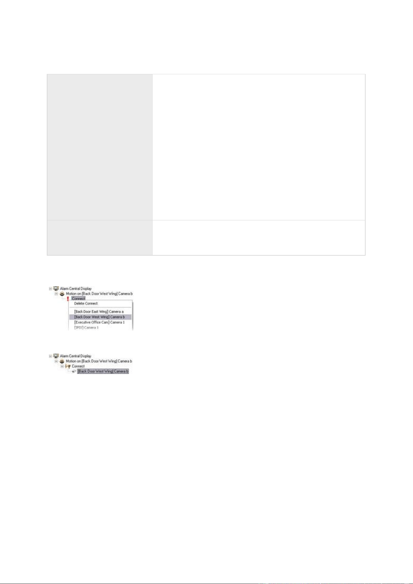
XProtect Professional VMS 2016 R3 - Administrator Manual
Advanced configuration
137
Disconnect, then connect
Disconnect any existing connections, then connect again.
With this option the live video appears in the Matrix recipient on a
first-in-first-out basis. Each time a new event occurs, video from
the latest event is displayed prominently in a specific position on
the Matrix recipient, while at the same time video from the older
events is shifted to less prominent positions and eventually
”pushed out” of the Matrix recipient in order to make space for
the latest event's video.
With the Connect option, you may experience that if video
triggered by one event on a camera is already shown on the
Matrix recipient, videos triggered by another event on the same
camera are not displayed prominently as coming from the latest
event because the Matrix recipient is already showing video from
the camera in a less prominent position.
By selecting Disconnect, then connect you can avoid this issue,
and ensure that video from the latest event is always displayed
prominently.
Disconnect
Disconnects any existing connection. Use if a particular event
should cause video to stop being displayed in the Matrix-
recipient, even if they are not yet old enough to be “pushed out”
of the Matrix-recipient.
If you selected Connect, another red exclamation mark indicates that there is still some
configuration to do. Right-click an action to select which camera to apply the action on.
In this example, we have specified that when motion is detected on Camera b, the selected Matrix-
recipient should connect to Camera b:
Logs
About logs
Your system can generate various logs that shows the activity on system functionality. The
following log types are available in your system:

XProtect Professional VMS 2016 R3 - Administrator Manual
Advanced configuration
138
Name
Description
Management Application log
files
Shows Management Application activity. The system creates a
new log file for every day you use the Management Application.
You cannot disable this type of logging. Management Application
log files are named according to the structure
AdminYYYYMMDD.log, for example Admin20091231.log.
Recording Server service log
files
Shows Recording Server service activity. A new log file is created
for each day this service is used.
You cannot disable this type of logging. Recording Server service
log files are named according to the structure
RecordingServerYYYYMMDD.log, for example
RecordingServer20091231.log.
Image Server service log
files
Shows Image Server service activity. A new log file is created for
each day the service is used.
You cannot disable this type of logging. Image Server service log
files are named according to the structure ISLog_YYYYMMDD.log,
for example ISLog_20091231.log.
Image Import service log
files
Shows Image Import service activity, when this service is used
for fetching pre-alarm images, and storing the fetched images in
camera databases.
Pre-alarm images is a feature available for selected cameras only.
It enables sending of images from immediately before an event
took place from the camera to the surveillance system via e-mail.
A new log file is created for each day the service is used.
You cannot disable this type of logging. Image Import service log
files are named according to the structure
ImageImportLog_YYYMMDD.log, for example
ImageImportLog20091231.log.
Event log files
Shows registered events' activity. A new log file is created for
each day on which events occur.
You cannot disable this type of logging. Event log files should be
viewed using XProtect Smart Client (use the Playback tab's
Alerts section).
Audit log files
Shows XProtect Smart Client user activity (if audit logging is
enabled).
A new log file is created for each day with audit logging enabled
and client user activity. Audit log files are named according to the
structure is_auditYYYMMDD.log, for example
is_audit20091231.log. The _is prefix is due to the fact that the
audit log files are generated by the Image Server service.
Log locations
All log files are by default placed in the appropriate All Users folder for the operating system you
are using. By default, they are stored there for seven days. Note that you can change log file
locations as well as the number of days to store the logs when you configure logging.

XProtect Professional VMS 2016 R3 - Administrator Manual
Advanced configuration
139
Log structures
Most log files generated by your system use a shared structure complying with the W3C Extended
Log File Format. Each log file consists of a header and a number of log lines:
The header outlines the information contained in the log lines.
The log lines consist of two main parts: the log information itself as well as an encrypted
part. The encrypted part makes it possible, through decryption and comparison, to assert
that a log file has not been tampered with.
Log integrity checks
All log files, except Management Application log files, are subjected to an integrity check once
every 24 hours. The integrity check is performed by your system's Log Check service. The result of
the integrity check is automatically written to a file named according to the structure
LogCheck_YYYYMMDD.log, for example LogCheck_20091231.log. Like the log files themselves, the
log check files are by default placed in the appropriate All Users folder for the operating system
you are using.
Any inconsistencies are reported in the form of error messages written in the log check file.
Possible error messages:
Name
Description
Log integrity information
was not found. Log integrity
can't be guaranteed.
The log file could not be checked for integrity.
Log information does not
match integrity information.
Log integrity can't be
guaranteed.
The log file exists, but does not contain the expected information.
Log integrity cannot be guaranteed.
[Log file name] not found
The log file was not present.
[Log file name] is empty
The log file was present, but empty.
Last line changed/removed
in [log file name]
The last line of the log file did not match the validation criteria.
Encrypted data missing in
[log file name] near line [#]
The encrypted part of the relevant log line was not present.
Inconsistency found in [log
file name] near line [#]
The log line does not match the encrypted part.
Inconsistency found in [log
file name] at beginning of
log file
The log file header is not correct. This situation is most likely to
occur if a user has attempted to delete the beginning of a log file.

XProtect Professional VMS 2016 R3 - Administrator Manual
Advanced configuration
140
Note: Other messages that are not error-related may also appear in the log check file.
Configure system, event and audit logging
Your system can generate various logs. To configure logging, do the following:
1. Expand Advanced Configuration, right-click Logs and select Properties.
2. Specify properties (see "Log properties" on page 140) for your system logs, including the
event log and the audit log. Administrators can only disable/enable audit logging. All other
logs are compulsory.
3. Save your configuration changes by clicking Save in the yellow notification bar in the
upper-right corner of the Management Application.
Log properties
Your system can generate various types of logs. When you configure logs, you can define the
following:
General Logs
Management Application log, Recording Server service log, Image Server service log, and Image
Import service log
Path
These log files are by default placed in the appropriate All Users
folder for the operating system you are using.
To specify another location for your log files, type the path to the
required folder in the Path field, or click the browse button next
to the field to browse to the required folder.
Days to log
A new log file is created for each day on which events occur. A
log file older than the number of days specified in the field is
automatically deleted. By default, the log file will be stored for
seven days. To specify another number of days (max. 9999),
simply overwrite the value in the field. The current day's activity
is always logged, even with a value of 0 in the field. Therefore, if
you specify 0, you will log current day's activity; if you specify 1,
you will keep one day plus the current day's activity, and so on.
Event Log
Path
These log files are by default placed in the appropriate All Users
folder for the operating system you are using.
To specify another location for your log files, type the path to the
required folder in the Path field, or click the browse button next
to the field to browse to the required folder.

XProtect Professional VMS 2016 R3 - Administrator Manual
Advanced configuration
141
Days to log
A new log file is created for each day on which events occur. A
log file older than the number of days specified in the field is
automatically deleted. By default, the log file will be stored for
seven days. To specify another number of days (max. 9999),
simply overwrite the value in the field. The current day's activity
is always logged, even with a value of 0 in the field. Therefore, if
you specify 0, you will log current day's activity; if you specify 1,
you will keep one day plus the current day's activity, and so on.
Audit Log
Enable audit logging
Audit logging is the only type of system logging which is not
compulsory. Select/clear the check box to enable/disable audit
logging.
Path
These log files are by default placed in the appropriate All Users
folder for the operating system you are using.
To specify another location for your log files, type the path to the
required folder in the Path field, or click the browse button next
to the field to browse to the required folder.
Days to log
A new log file is created for each day with audit logging enabled
and client user activity. A log file older than the number of days
specified in the field is automatically deleted. By default, the log
file is stored for seven days. To specify another number of days
(max. 9999), overwrite the value in the field. The current day's
activity is always logged (provided audit logging is enabled and
there is user activity). Therefore, if you specify 1, you keep one
day plus the current day's activity. Note that if you specify 0
(zero), audit log files are kept indefinitely (disk space permitting).
Minimum logging interval
Minimum number of seconds between logged events. Specifying a
high number of seconds between logged events may help reduce
the size of the audit log. Default is 60 seconds.
In sequence timespan
The number of seconds to pass for viewed images to be
considered to be within the same sequence. Specifying a high
number of seconds may help limit the number of viewed
sequences logged and reduce the size of the audit log. The
default is ten seconds.
Notifications
About notifications
In case of problems with hardware, activation of motion detection on your camera or similar
incidents, you can set up your system to send notifications through SMS and/or email.

XProtect Professional VMS 2016 R3 - Administrator Manual
Advanced configuration
142
Email
About email
With email notifications, you can instantly get notified when your surveillance system requires
attention. Your system can automatically send e-mail notifications to one or more recipients when:
Motion is detected
Events occur. You can select individually for each event whether you want to receive an
email notification or not.
Archiving fails (if email notification has been selected as part of the archiving properties)
Configure email notifications
To set up email notifications, do the following:
1. Expand Advanced Configuration, expand Notifications, right-click Email and select
Properties.
2. Enable the use of email by selecting the Enable email check box.
3. Specify required properties (see "Message Settings (email)" on page 142).
4. Choose a schedule profile to associate with your email notifications. Your system comes
with two simple schedule profiles, Always on and Always off, which you cannot edit or
delete. If these do not meet your needs, you can create any number of customized
schedule profiles for each camera. You can reuse a customized schedule profile for more
than one purpose if you want to.
Email (Properties)
Message Settings (email)
Specify the following message settings for email:
Enable
Select to enable the use of email notifications, allowing you to
specify further properties.
Recipient(s)
Specify the email addresses to which the system should send
email notifications. To specify more than one e-mail address,
separate the e-mail addresses with semicolons (example:
Subject text
Enter a subject text for email notifications.
Message text
Enter a message text for email notifications. Note that camera
information as well as date and time information is automatically
included in email notifications.

XProtect Professional VMS 2016 R3 - Administrator Manual
Advanced configuration
143
Variables
Click a link to include a variable to the notification. The options
are:
Name of triggering event
Camera name
Trigger time (the time when the notification was registered)
Error text (for example, camera failure)
Ignore similar messages
for:
Specify the number of seconds to ignore sending similar
notifications. This function is to ensure that you do not receive
too many notifications before you have solved the relevant
problem.
Use schedule profile
Select the schedule profile you want to use. By default, you can
choose between Always On, Always Off or choose Add new...
to set up a custom schedule (see "Notification Scheduling
properties" on page 146).
Attachment Settings (email)
Specify the following attachment settings:
Include images
Select the check box to include still images in email notifications.
When selected, each email notification includes one or more
attached still JPEG images.
Attached images includes images of before the incident, after the
incident and the actual incident, with the incident that triggered
the notification in the middle.
Important: If your device does not record any images while the
sending of notifications are turned on, no images are included in
the email notification you receive.
Number of images
The number of images you want to include in the email. You can
include between 1 and 20 images.
Time between images (ms)
Minimum time (in milliseconds) to be between each image. You
can set any time range between 0 and 300 seconds (5 minutes).
Embed images in email
Select the check box to embed images directly in the email.
Server Settings (email)
Specify the following server settings for email:
Sender e-mail address
Enter the email address you wish to use as the sender of the
email notification.

XProtect Professional VMS 2016 R3 - Administrator Manual
Advanced configuration
144
Outgoing mail server
address (SMTP)
Type the name of the SMTP (Simple Mail Transfer Protocol) server
that you want to use to send the email notifications.
Compared with other mail transfer methods, SMTP has the
advantage that you avoid automatically triggered warnings from
your email client. Such warnings may otherwise inform you that
your email client is trying to automatically send email messages
on your behalf.
TLS (Transport Layer Security) and its predecessor, SSL (Secure
Socket Layer), are supported.
Outgoing mail server port
(SMTP)
Type the port for your mail server. The default port number is 25.
Server requires login
Select the check box if you must use a user name and password
to use the SMTP server.
Security type
Choose the type of security you want to use.
User name
Specify the user name required for using the SMTP server.
Only relevant when you have selected Server requires login.
Password
Specify the password required for using the SMTP server.
Only relevant if you have selected Server requires login.
Max attachment size (MB)
Specify a maximum size of attached images.
SMS
About SMS
Available functionality depends on the system you are using. See the Product comparison chart (on
page 11) for more information.
With SMS notifications, you can instantly get notified on your mobile device when your surveillance
system requires attention. To use the SMS notification feature, you must connect a 3G/USB
modem to the server on which you have installed your system.
Your system can automatically send SMS notifications when:
Motion is detected
Events occur. You can select individually for each event whether you want to receive an
SMS notification or not.
Archiving fails (if an SMS notification has been selected as part of the archiving properties).
Configure SMS notifications
Available functionality depends on the system you are using. See the Product comparison chart (on
page 11) for more information.
To configure SMS notifications, do the following:

XProtect Professional VMS 2016 R3 - Administrator Manual
Advanced configuration
145
1. Expand Advanced Configuration, expand Notifications, right-click SMS and select
Properties.
2. Enable the use of SMS by selecting the Enable SMS check box.
3. Specify required properties.
4. Choose a schedule profile to associate with your SMS notifications.
Note: Your system comes with two simple schedule profiles, Always on and Always off, which
you cannot edit or delete. If these do not meet your needs, you can create any number of
customized schedule profiles for each camera. You can reuse a customized schedule profile for
more than one purpose if you want to.
SMS properties
Message Settings (SMS)
Available functionality depends on the system you are using. See the Product comparison chart (on
page 11) for more information.
Specify the following message settings for SMS:
Enable SMS
Enables the use of SMS notifications, allowing you to specify
further properties.
Recipient(s)
Indicate the telephone number of the recipient. To send SMS to
more than one recipient, separate the phone numbers with a
semicolon.
Message text
Specify required message text for the SMS notification. Message
text must only contain the following characters: a-z, A-Z, 0-9 as
well as commas (,) and full stops (.). Note that camera
information, date and time information are all automatically
included in SMS notifications.
Variables
Click a link to include a variable to the notification. The options
are:
Name of triggering event
Camera name
Trigger time (the time when the notification was registered)
Error text (for example, camera failure)
Ignore similar messages
for:
Specify the number of seconds to ignore sending similar
notifications. This function is to ensure that you do not receive
too many notifications before you have solved the relevant
problem.
Use schedule profile
Select the schedule profile you want to use. By default, you can
choose between Always On, Always Off or choose Add new...
to set up a custom schedule (see "Notification Scheduling
properties" on page 146).

XProtect Professional VMS 2016 R3 - Administrator Manual
Advanced configuration
146
Server Settings (SMS)
Available functionality depends on the system you are using. See the Product comparison chart (on
page 11) for more information.
Specify the following server settings for SMS:
Serial port
Select the serial port to use for your USB/3G modem. The list
that allows you to choose ports shows open serial ports on the
computer running your system.
Speed
The baud speed of your USB modem device. The default value is
9600 baud. Although you can set any custom value for the baud
rate, Milestone does not recommend that you change the baud
rate unless you are a highly advanced user.
SIM card PIN code
Specify PIN code for the SIM card inserted in the USB/3G
modem.
SMS encoding
Different types of SMS encodings exist to accommodate various
language needs in the world. Your system offers you the following
options:
7-bit
8-bit (default)
16-bit
7-bit encryption allows you to use up to 160 characters per SMS,
however it also limits the type of characters you can use.
8-bit encryption is the standard form of encryption with more
special characters allowed. It allows you to use up to 140
characters per SMS.
16-bit encryption is necessary for non-Latin alphabet languages.
Characters from, for example, Arabic, Chinese, Korean, Japanese
or Cyrillic alphabet languages require 16-bit SMS encoding. If you
use any of these languages in your organization, you must set
your system to use 16-bit encoding. 16-bit has a limit of 70
characters per SMS.
Scheduling
About scheduling of notifications
Scheduling of notifications allows you to set up schedule profiles which you can use with Email (see
"Message Settings (email)" on page 142) and SMS (see "Message Settings (SMS)" on page 145)
notifications.
Notification Scheduling properties
When you set up schedules to use with email or SMS notifications, specify the following:

XProtect Professional VMS 2016 R3 - Administrator Manual
Advanced configuration
147
Notification profile
Select the relevant profile (for example Always on) for your
notification schedule profile.
You specify a notification schedule profile by creating schedule
profiles based on:
Periods of time (example: Mondays from 08.30 until 17.45),
shown in blue:
Central
About Central
Central Settings lets you specify the login settings required for an XProtect Central server to
access the surveillance system in order to retrieve status information and alarms.
If you are a user of the MIP, this is also the dialog that lets you specify the login settings for the
MIP to access the surveillance system.
Enable XProtect Central
1. Expand Advanced Configuration, right-click Central and then select Properties.
2. Enable the use of Central connections by selecting the Enable Milestone XProtect
Central check box.
3. Specify required properties.
4. Save your configuration changes by clicking Save in the yellow notification bar in the
upper-right corner of the Management Application.
Central properties
Specify the following propeties for Central:
Enable Milestone XProtect
Central connections
Enables the use of Central connections, allowing you to specify
further properties.
Login Name
Type the name used for the connection between your system and
Central servers or the MIP. The name must match the name
specified on the Central server or in the MIP.
Password
Type the password used for the connection between system and
Central servers or the MIP. The password must match the
password specified on the Central server or in the MIP.
Port
Type the port number to which the XProtect Central server or the
MIP should connect when accessing the surveillance system
server. The port number must match the port number specified
on the XProtect Central server or in the MIP. The default port is
1237.

XProtect Professional VMS 2016 R3 - Administrator Manual
Advanced configuration
148
Access control
About access control integration
The use of XProtect Access requires that you have purchased a base license that allows you to
access this feature within your XProtect system. You also need an access control door license for
each door you want to control.
You can use XProtect Access with access control systems from vendors where a vendor-specific
plug-in for XProtect Access exists.
Available functionality depends on the system you are using. See the Product comparison chart (on
page 11) for more information.
The access control integration feature introduces new functionality that makes it simple to
integrate customers’ access control systems with XProtect. You get:
A common operator user interface for multiple access control systems in XProtect Smart
Client.
Faster and more powerful integration of access control systems.
More functionality for the operator (see below).
In XProtect Smart Client, the operator gets:
Live monitoring of events at access points.
Operator aided passage for access requests.
Map integration.
Alarm definitions for access control events.
Investigation of events at access points.
Centralized overview and control of door states.
Cardholder information.
Apart from a base license and access control door licenses, you need a vendor-specific integration
plug-in installed on the event server before you can start an integration.
The maximum number of doors that you can integrate with XProtect Professional VMS Products is
1000. If more doors are available in the configuration that you import from your access control
system, the integration stops.
XProtect Access licenses
XProtect Access requires the following access control-related licenses:
A base license for XProtect Access that covers an unlimited number of Access servers.

XProtect Professional VMS 2016 R3 - Administrator Manual
Advanced configuration
149
An access control door license per door you want to integrate and control in XProtect
Access. Two access control door licenses are included with the XProtect Access base
license. All door licenses are automatically installed when you install your XProtect
Access product. However, the installed door licenses are by default disabled which
means that you must enable the doors that you want to use. You can only enable as
many doors as you have door licenses for.
Example: You have five access control door licenses and you have added 10 doors. Once you have
added five doors, you cannot select any more. You must remove some of your doors before you
can add another door.
To find information about the current status of your access control door licenses, expand the
Access Control node.
To buy additional XProtect Access base licenses or door licenses, contact your vendor.
Wizard for access control system integration
The Access control system integration wizard is for step-by-step configuration of the initial
integration with an access control system. Use the wizard to get through the most basic
configuration tasks. You can do more detailed configuration afterwards.
Before you start the access control integration wizard make sure you have the integration plug-in
installed on the event server.
Some of the fields to fill out and their default values are inherited from the integration plug-in.
Therefore, the appearance of the wizard may differ depending on the access control system you
integrate with.
To start the wizard, select Access Control in the node tree, right-click, and click Create new.
Create access control system integration
Enter the name and specify the connection details for the access control system you want to add.
The parameters that you must specify depend on the type of system, but are typically the network
address of the access control system server and an access control administrator user name and
password.
The video management system uses the specified user name and password to log into the access
control system for retrieving the full configuration.
The integration plug-in may also define secondary parameters which are not listed in the wizard,
but you can change these in General Settings after setting up the integration. The default values
for the parameters are supplied by the plug-in or the XProtect system.
Connecting to the access control system
When the plug-in has been successfully integrated, a summary of the retrieved access control
system configuration appears. Review the list to ensure that all items have been integrated before
you continue to the next step of the wizard.
Associated cameras
Map access points in the access control system with the cameras in the XProtect system, to show
related video for events from the doors.
You can map several cameras to one access point. The XProtect Smart Client user is then able to
view video from all the cameras when investigating events, for example.

XProtect Professional VMS 2016 R3 - Administrator Manual
Advanced configuration
150
The XProtect Smart Client user is also able to add one of the cameras when configuring Access
Monitor view items.
Licensed doors are by default enabled. Clear the check box to disable a door and thereby free an
access control door license.
Final summary
Your access control system integration has been successfully created in XProtect with default
settings inherited from the integration plug-in. Client users must log into XProtect Smart Client to
see and use the new access control system.
You can refine the configuration if needed.
Access control properties
General Settings tab (Access Control)
Name
Description
Enable
Systems are by default enabled, meaning that they are visible in
XProtect Smart Client for users with sufficient rights and that the
XProtect system receives access control events.
You can disable a system, for example during maintenance, to
avoid creating unnecessary alarms.
Name
The name of the access control integration as it appears in the
management application and in the clients. You can overwrite the
existing name with a new one.
Description
Provide a description of the access control integration. This is
optional.
Integration plug-in
Shows the type of access control system selected during the
initial integration.
Last configuration refresh
Shows the date and time of the last time the configuration was
imported from the access control system.
Refresh configuration
Click the button when you need to reflect configuration changes
made in the access control system in XProtect, for example if you
have added or deleted a door.
A summary of the configuration changes from the access control
system appears. Review the list to ensure that your access
control system is reflected correctly before you apply the new
configuration.
Operator login required
Enable an additional login for the client users, if the access
control system supports differentiated user rights.
This option is only visible if the integration plug-in supports
differentiated user rights.
The naming and content of the following fields are imported from the integration plug-in. Below are
examples of some typical fields:

XProtect Professional VMS 2016 R3 - Administrator Manual
Advanced configuration
151
Name
Description
Address
Type the address of the server that hosts the integrated access
control system.
Port
Specify the port number on the server to which the access control
system is connected.
User name
Type the name of the user, as defined in the access control
system, who should be administrator of the integrated system in
XProtect.
Password
Specify the password for the user.
Doors and Associated Cameras tab (Access Control)
This tab provides mappings between door access points and cameras, microphones or speakers.
You associate cameras as part of the integration wizard, but you can change the setup at any time.
Mappings to microphones and speakers are implicit through the related microphone or speaker on
the camera.
Name
Description
Doors
Lists the available door access points defined in the access control
system, grouped by door.
For an easier navigation to the relevant doors, you can filter on
the doors in your access control system with the dropdown list
box at the top.
Enabled: Licensed doors are by default enabled. You can disable
a door to free a license.
License: Shows if a door is licensed or if the license has expired.
The field is blank when the door is disabled.
Remove: Click Remove to remove a camera from an access
point. If you remove all cameras, the check box for associated
cameras is automatically cleared.
Cameras
Lists the cameras configured in the XProtect system.
Select a camera from the list, and drag and drop it at the relevant
access point to associate the access point with the camera.
Access Control Events tab (Access Control)
Event categories allow you to group events. The configuration of event categories affects the
behavior of access control in the XProtect system and allows you to, for example, define an alarm
to trigger a single alarm on multiple event types.

XProtect Professional VMS 2016 R3 - Administrator Manual
Advanced configuration
152
Name
Description
Access Control Event
Lists the access control events imported from the access control
system. The integration plug-in controls default enabling and
disabling of events. You can disable or enable events any time
after the integration.
When an event is enabled, it is stored in the XProtect event
database and is, for example, available for filtering in the
XProtect Smart Client.
Source Type
Shows the access control unit that can trigger the access control
event.
Event Category
Assign none, one or more event categories to the access control
events. The system automatically maps relevant event categories
to the events during integration. This enables a default setup in
the XProtect system. You can change the mapping at any time.
Built-in event categories are:
Access denied
Access granted
Access request
Alarm
Error
Warning
Events and event categories defined by the integration plug-in
also appear, but you can also define your own event categories,
see User-defined Categories.
Important: If you change the event categories in a Corporate
system, ensure that the existing access control rules still work.
User-defined Categories
Allows you to create, modify or delete user-defined event
categories.
You can create event categories when the built-in categories do
not meet your requirements, for example, in connection with
defining triggering events for access control actions.
The categories are global for all integration systems added to the
XProtect system. They allow setting up cross-system handling, for
example on alarm definitions.
If you delete a user-defined event category, you receive a
warning if it is used by any integration. If you delete it anyway,
all configurations made with this category, for example access
control actions, do not work anymore.
Access Control Actions tab (Access Control)
Actions specify the behavior of the access control system in XProtect Smart Client, based on the
configuration of the triggering events.

XProtect Professional VMS 2016 R3 - Administrator Manual
Advanced configuration
153
You can specify one or more actions related to:
An event category
Events from the access control system
Events from the XProtect system
Triggering events are from a specific access control unit or from a group of access control units.
Name
Description
Trigger Event
Select from the list an event category that should trigger an
action. The list includes built-in, plug-in and user-defined event
categories.
Select Access control event, to create a trigger based on
specific access control events instead of an event category.
Select External event, to create a trigger based on an input
event in the XProtect system.
Specify the input source in the Source field for each trigger.
Source
Select the source which the action affects. The options depend on
the setting of the Trigger Event field.
For event categories and access control events, select:
All doors
Individual doors
Other...
Click Other to select multiple doors, door access points or other
units in the access control system.
For external event:
Select the source from a list of events and input devices in the
XProtect system.
Time Profile
Select the time profile in which you want the action to be
performed if triggered.
Configure time profiles as part of Advanced Configuration.
Action
Select the type of action:
Display access request notification
Go to PTZ preset
Start recording
System action
For each action, specify action details.
To set up multiple actions, click Add access control action. You
can do this, for example, if you want different actions triggered
by the same event depending on weekend vs. office hours.

XProtect Professional VMS 2016 R3 - Administrator Manual
Advanced configuration
154
Add access control action
Click to add and define actions as required.
Action details
Configure the parameters for an action:
Display access request notification:
Specify which cameras, microphones or speakers the XProtect
Smart Client user connects to via the notification user
interface when a given event occurs. Also specify the sound to
alert the user when the notification pops up. To enable more
commands in the notification, see Add Command.
Go to PTZ preset:
Specify the camera and select from the pre-configured
presets a pattern for the camera and the time of return to
preset when a given event occurs.
Start recording:
Specify the cameras that should start recording and the
duration when a given event occurs.
System action:
Specify an action predefined in the XProtect system.
Add command
Select which commands that should be available as buttons in the
access request notification dialogs in the XProtect Smart Client.
Related access request commands:
Enables all commands related to access request operations
available on the source unit. For example Open door.
All related commands:
Enables all commands on the source unit.
Access control command:
Enables a selected access control command.
System command:
Enables a command predefined in the XProtect system.
To delete a command, click X on the right side.
Cardholders tab (Access Control)
Use the Cardholders tab to review information about cardholders in the access control system.
Name
Description
Search cardholder
Type the characters of a cardholder name and it appears in the
list, if it exists.
Name
Lists the names of the cardholders retrieved from the access
control system.

XProtect Professional VMS 2016 R3 - Administrator Manual
Advanced configuration
155
Name
Description
Type
Lists the type of cardholder, for example:
Employee
Guard
Guest
If your access control system supports adding/deleting pictures in the XProtect system, you can
add pictures to the cardholders. This is useful if your access control system does not include
pictures of the cardholders.
Name
Description
Select picture
Specify the path to a file with a picture of the cardholder. This
button is not visible if the access control system manages the
pictures.
Allowed file-formats are .bmp, .png, and .jpg.
Pictures are resized to maximize the view.
Milestone recommends that you use a quadratic picture.
Delete picture
Click to delete the picture. If the access control system had a
picture, then this picture is shown after deletion.
Server access
About server access
You can configure clients' access to your system's server in two ways:
Wizard-driven: Specify how clients access the server and which users can use clients
through guided configuration. When you use the wizard, all users that you add have access
to all cameras, including new cameras added at a later stage. If this is not what you want,
specify access settings, users and user rights separately.
Through advanced configuration: This was known as Image Server administration in
previous versions.
About registered services
Registered services displays the services installed and running on your system. It displays the
following information about the individual services:
Name
Description
Enabled
Indicates if the relevant service is enabled.
Name
The name of the service.
Description
A description of the service.

XProtect Professional VMS 2016 R3 - Administrator Manual
Advanced configuration
156
Name
Description
Addresses
The inside and outside addresses used by the service.
You can change the inside and outside addresses for a service. To do this, click the Edit button and
enter the relevant inside and/or outside addresses. Note that you cannot edit all services. You can
delete a service registration from the system by clicking the Delete button. You are prompted for
confirmation before the service is deleted.
Configure server access
1. Expand Advanced Configuration, right-click Server Access and select Properties.
2. Specify required properties for Server Access, Local IP Ranges, and Language Support and
XML Encoding. Your system comes with two simple schedule profiles, Always on and
Always off, which you cannot edit or delete. If these do not meet your needs, you can
create any number of customized schedule profiles for each camera. You can reuse a
customized schedule profile for more than one purpose if you want to.
3. Save your configuration changes by clicking Save in the yellow notification bar in the
upper-right corner of the Management Application.
When you use this option, you configure client users separately from clients' access. See Add
individual users, Add user groups, and Configure user and group rights.
Server access properties
Server access
You can configure client's access to the system server or server access. Specify the following:
Server name
Name of the surveillance system server as it appears in clients.
Client users with rights to configure their clients see the name of
the server when they create views in their clients.
Local port
Port number to use for communication between clients and the
surveillance server. The default port number is 80; you can
change the port number if port 80 is used for other purposes in
your organization.
Enable Internet access
Select the check box if the server should be accessible from the
Internet through a router or firewall.
If you select this option, also specify the public (“outside”) IP
address and port number in the following fields. When using
public access, the router or firewall used must be configured so
requests sent to the public IP address and port are forwarded to
the local (“inside”) IP address and port of the surveillance system
server.
Internet address
Specify a public IP address or hostname for use when the system
server should be available from the Internet.

XProtect Professional VMS 2016 R3 - Administrator Manual
Advanced configuration
157
Internet port
Specify a port number for use when the system should be
available from the Internet. The default port number is 80. You
can change the port number if needed.
Max. number of clients
You can limit the number of clients allowed to connect at the
same time. Depending on your system configuration and the
performance of the hardware and network used, limiting the
number of simultaneously connected clients may help reduce
server load. If more than the allowed number of simultaneously
connected clients attempt to log in, only the allowed number of
clients are allowed access. Any clients in excess of the allowed
number receive an error message when attempting to log in.
By default, a maximum of ten simultaneously connected clients
are allowed. To specify a different maximum number, overwrite
the value.
To allow an unlimited number of simultaneously connected access
clients, type 0 (zero) in the Max. number of clients field.
A four-minute session timeout period applies for client sessions
on the system. In many cases, client users may not notice this at
all. Note that the session timeout period is very evident if you set
the max. number of clients value to 1. When that is the case, and
the single allowed client user logs out, four minutes must pass
before you can log in again.
Local IP ranges
You can specify IP address ranges which your system should recognize as coming from a local
network. This can be relevant if different subnets are used across your local network.
If you click the Add button, you can set:
Start Address
Specify the first IP address in the range.
End Address
Specify the last IP address in the range.
Repeat the process if you want to add other local IP address ranges.
Language support and XML encoding
You can select the language/character set that should be used by your system's server and clients.

XProtect Professional VMS 2016 R3 - Administrator Manual
Advanced configuration
158
Character
encoding/Language
Select relevant the language/character set.
Example: Select Japanese if your surveillance system server is
running on a Japanese version of Windows. If the clients you use
to access the system also run on a Japanese version of Windows,
the Japanese language/character set ensure that the correct
language and character encoding is in the communication
between clients and the server.
If you are running a master/slave setup, remember to specify the
same language/character set on all relevant servers.
Only XProtect Enterprise and XProtect Professional support
master/slave functionality.
Master/Slave
About master and slave
Available functionality depends on the system you are using. See the Product comparison chart (on
page 11) for more information.
A master/slave setup allows you to combine several servers and extend the total number of
cameras you can use beyond the maximum allowed number of cameras for a single server. A
master/slave setup also allows remote users to transparently connect to more than one server at
the same time. When remote users connect to the master server, they instantly get access to feeds
from hardware devices on the slave servers as well.
You can designate an unlimited number of master and slave servers per software license file.
XProtect Enterprise master servers can only use XProtect Enterprise slave servers while XProtect
Professional master servers can use both XProtect Enterprise and XProtect Professional slave
servers.
You can have different product versions on the master and the slaves servers, but the master
server must use the newest version of the software and the slave servers must not run versions
that go more than two versions back compared to the product running on the master server.
You can verify the connection to your slaves by clicking Update Status and let the system report
the number of connected slaves back to you.
Configure master and slave servers
Available functionality depends on the system you are using. See the Product comparison chart (on
page 11) for more information.
1. Expand Advanced Configuration, right-click Master/Slave and select Properties.
2. Select the Enable as master server check box.
3. Click Add to add a slave server.
4. Specify slave server properties. When ready, click OK.

XProtect Professional VMS 2016 R3 - Administrator Manual
Advanced configuration
159
Master/slave properties
You can set the following properties for master servers and slave servers:
Master server properties
Enable as master server
Select to enable as master server.
Timeout
Set timeout of slave update. See Update Status on Slaves
further below.
Add
Lets you add slave servers. Select Master Server in the list and
click the Add button.
Pre version 8.0 slaves
Select this to enable support of slaves running XProtect
Enterprise versions prior to version 8.0.
Selecting Pre version 8.0 slaves disables the update slave status
feature for all slaves, both pre 8.0 and beyond.
When you select Master Server, the Delete button is disabled and the Add button is enabled
(provided you have selected Enabled as master server). This allows you to add slave servers to
the master server, but prevents you from deleting the master server.
Slave server properties
Address
IP address of the slave server.
Port
Port number of the slave server.
Delete
Remove a slave server from the list of slave servers. Select the
slave server in the list and click the Delete button.
If you want a slave server to become a master server, clear Enable as master server on the
original master server and click OK. In the navigation pane, right-click the slave server which you
want to become master server and select Properties. Then select Enable as master server.
Next click Add to add slave servers to the new master server.
Update status on slaves
In the Master Settings Summary and Slave Settings Summary table area, you can
verify/update added slaves by clicking Update Status. A status dialog runs and afterwards informs
you of the status of your slave server(s).
If you select Pre version 8.0 slaves, you cannot update slave status on any slaves and Update
Status is therefore disabled. In the Slave Settings Summary table, slave status on all slaves is
Not applicable.
If you do not select Pre version 8.0 slaves, slave status for pre version 8.0 slaves is
Unreachable. Slave status for 8.0 slaves and beyond reflects the actual status.

XProtect Professional VMS 2016 R3 - Administrator Manual
Advanced configuration
160
Users
About users
The term users primarily refers to users who connect to the surveillance system through their
clients. You can configure such users in two ways:
As basic users, authenticated by a user name/password combination.
As Windows users, authenticated based on their Windows login
You can add both types of users through the Configure User Access wizard or individually (see Add
basic users (on page 160) and Add Windows users (on page 160)).
By grouping users, you can specify rights for all users within a group in one go. If you have many
users performing similar tasks, this can save you significant amounts of work. User groups are
logical groups created and used for practical purposes in the Management Application only. They
are not in any way connected with user groups from central directory services. If you want to use
groups, make sure you add groups before you add users: you cannot add existing users to groups.
Finally, the Administrators group is also listed under Users. This is a default Windows user group
for administration purpose which automatically has access to the Management Application.
Add basic users
When you add a basic user, you create a dedicated surveillance system user account with basic
user name and password authentication for the individual user. Note that creating Windows users
provides better security. If you want to include users in groups, make sure you add required
groups before you add users. You cannot add existing users to groups.
You can add basic users in two ways: One is through the Configure User Access wizard.
Alternatively, add basic users this way:
1. Expand Advanced Configuration, right-click Users, and select Add New Basic User.
2. Specify a user name. Specify a password, and repeat it to be sure you have specified it
correctly. Click OK.
3. Specify General Access and Camera Access properties. These properties determine the
rights of the user. Click OK.
4. Save your configuration changes by clicking Save in the yellow notification bar in the
upper-right corner of the Management Application.
Add Windows users
When you add Windows users, you import users defined locally on the server and authenticate
them based on their Windows login. This generally provides better security than the basic user
concept, and it is the method Milestone recommends. If you want to include users in groups, make
sure you add required groups before you add users. You cannot add existing users to groups.
Add Windows users in two ways: One is through the Manage user access wizard. Alternatively, add
Windows users this way:
1. Expand Advanced Configuration, right-click Users, and select Add New Windows
User. This opens the Select Users or Groups dialog.

XProtect Professional VMS 2016 R3 - Administrator Manual
Advanced configuration
161
the Locations... button.
2. In the Enter the object names to select box, type the relevant user name(s), then use
the Check Names feature to verify it. If you type several user names, separate each name
with a semicolon. Example: Brian; Hannah; Karen; Wayne
3. When done, click OK.
4. Specify General Access and Camera Access properties. These properties determine the
rights of the user.
5. Click OK.
6. Save your configuration changes by clicking Save in the yellow notification bar in the
upper-right corner of the Management Application.
Users added from a local database logging in with a client should not specify any server name, PC
name, or IP address as part of the user name. Example of a correctly specified user name:
USER001. Example of an incorrectly specified user name: PC001/USER001. The user should still
specify a password and any required server information.
Add user groups
User groups are logical groups created and used for practical purposes in the Management
Application only. They are not in any way connected with user groups from central directory
services.
By grouping users, you can specify rights (see "Configure user and group rights" on page 161) for
all users within a group in one go. If you have many users performing similar tasks, this can save
you significant amounts of work. Make sure you add groups before you add users: you cannot add
existing users to groups.
1. Expand Advanced Configuration, right-click Users, and select Add New User Group.
2. Specify a name. Names must be unique, and must not contain any of these special
characters: < > & ' " \ / : * ? | [ ]
3. Click OK.
4. Specify General access (on page 162) and Camera access (on page 164) properties. These
properties will determine the rights of the group's future members.
5. Click OK.
6. Save your configuration changes by clicking Save in the yellow notification bar in the
upper-right corner of the Management Application.
7. Now you can add users to the group: in the navigation pane, right-click the group you just
created, and Add basic users (on page 160) or Add Windows users (on page 160) as
required.
Configure user and group rights
User/group rights are configured during the process of adding users/groups, see Add basic Users
(on page 160), Add Windows users (on page 160) and Add user groups (on page 161). Note that
you can also add basic and Windows users through the Manage user access wizard (on page 60).
When you use the wizard, all users you add gain access to all cameras, including any cameras
added at a later stage.

XProtect Professional VMS 2016 R3 - Administrator Manual
Advanced configuration
162
If you want to edit the rights of a user or group:
1. Expand Advanced Configuration, expand Users, right-click the required user or group,
and select Properties.
2. Set the required user rights under the relevant tabs shown. The properties you set here
determine the rights of the user/group. Click OK.
3. Save your configuration changes by clicking Save in the yellow notification bar in the
upper-right corner of the Management Application.
User properties
User information
You can change the following user information:
User name
Edit the user name. You can only edit this if the selected user is a
basic user. Names must be unique, and must not contain any of
these special characters: < > & ' " \ / : * ? | [ ]
Password
Edit the password. Remember to repeat the password to be sure
you have specified it correctly.
You can only edit the password for basic users.
User type
You cannot edit this field. It shows whether the selected user is a
basic user or a Windows user group.
Group information
Group name
Edit the group name. Names must be unique, and must not
contain any of these special characters: < > & ' " \ / : * ?
| [ ]
General access
Specify the following settings for General access when you add or edit basic users (see "Add basic
users" on page 160), Windows users (see "Add Windows users" on page 160) or groups (see "Add
user groups" on page 161):
Client access settings
Live
Enables access to the Live tab in XProtect Smart Client.
Playback
Enables access to the Playback tab in XProtect Smart Client.
Setup
Enables access to setup mode in XProtect Smart Client.

XProtect Professional VMS 2016 R3 - Administrator Manual
Advanced configuration
163
Edit shared views
Enables the user to create and edit views in shared groups in
XProtect Smart Client.
Every user can access views placed in shared groups. If a
user/group does not have this right, shared groups are protected,
indicated by a padlock icon in XProtect Smart Client.
Edit private views
Enables the user to create and edit views in private groups in
XProtect Smart Client.
Views placed in private groups can only be accessed by the user
who created them. If a user/group does not have this right,
private groups will be protected, indicated by a padlock icon in
XProtect Smart Client. Denying users the right to create their own
views may make sense in some cases, for example, to limit
bandwidth use.
For more information about shared and private views, see the
separate XProtect Smart Client documentation.
Clear the Live, Playback and Setup check boxes to disable the user/group's ability to use
XProtect Smart Client. You can use this as a temporary alternative to deleting the user/group if a
user/group is not going to use an account for a period of time.
Management Application access
Administrator Access
Enables the user to access and work with the Management
Application.
If you have more than one Administrator member, you can clear
the check box to ensure that other administrators cannot access
the Management Application.
Login authorization
This user/group requires
authorization from another
user to log in
Enables a restriction on the user/group which means that a
second user must authorize the log in before the user/group can
log in to XProtect Smart Client or the Management Application.
This user/group can
authorize logins from other
users
Enables the right for this user/group to authorize the log in for
other users in XProtect Smart Client or the Management
Application.
At least one person on the system must have a full administrator access with no authorization of
log in. This is why the administrator should ensure that all proper user rights are given to other
users of the system. If there are no users to authorize, the This user/group requires
authorization from another user to log in checkbox is not available and you cannot change its
settings.
If there is only one user on the system, the This user/group can authorize logins from other
users check box is not available and you cannot change its settings.

XProtect Professional VMS 2016 R3 - Administrator Manual
Advanced configuration
164
Camera access
Available functionality depends on the system you are using. See the Product comparison chart (on
page 11) for more information.
When you add or edit basic users (see "Add basic users" on page 160), Windows users (see "Add
Windows users" on page 160) or groups (see "Add user groups" on page 161), you can specify
camera access settings.
In the list of cameras, select the camera(s) you want to work with. Note the last item in the list,
Rights for new cameras when added to the system, with which you can allow the user/group
access to any future cameras.
Tip: Use SHIFT or CTRL to select multiple cameras the same features should be available for
access for several cameras, you can select multiple cameras by pressing SHIFT or CTRL on your
keyboard while you select.
For the selected camera(s), in the Access check box, specify if the user/group should have access
to live viewing and playback at all. If so, specify if they should have access to both live viewing
and playback and—if this is the case—which sub-features should be available when you work with
the selected camera(s). The sub-features are listed in two columns in the lower part of the window:
the left column lists features related to live viewing, the right column lists features related to
playback.
The Camera access settings check boxes work like a hierarchy of rights. If the Access check box
is cleared, everything else is cleared and disabled. If the Access check box is selected, but, for
example, the Live check box is cleared, everything under the Live check box is cleared and
disabled.
Depending on the selected column, the following default features for live or playback from the
selected camera(s) give you the ability to:
Live
Features
PTZ
Use navigation features for PTZ (Pan-tilt-zoom) cameras.
A user/group can only use this right if the user has access to one
or more PTZ cameras.
PTZ preset positions
Use navigation features for moving a PTZ camera to particular
preset positions. A user/group can only use this right if the
user/group has access to one or more PTZ cameras with defined
preset positions.
Manage PTZ presets
Manage PTZ positions in XProtect Smart Client.
Output
Activate output related to the selected camera(s).
Events
Use manually triggered events related to the selected camera(s).
This feature is available in XProtect Smart Client only.
Incoming audio
Listen to incoming audio from microphones related to the
selected camera(s). This feature is available in XProtect Smart
Client only.
Manual recording
Manually start recording for a fixed time (defined (see "Manual
recording" on page 82) by the surveillance system administrator).
Outgoing audio
Talk to audiences through speakers related to the selected
camera(s). This feature is available in XProtect Smart Client only.

XProtect Professional VMS 2016 R3 - Administrator Manual
Advanced configuration
165
Playback
Features
AVI/JPEG export
Export evidence as movie clips in AVI format and as still images
in JPEG format.
Database export
Export evidence in database format. This feature is available in
XProtect Smart Client only.
Sequences
Use the Sequences feature when playing back video from the
selected camera.
Smart search
Search for motion in one or more selected areas of images from
the selected camera. This feature is available in XProtect Smart
Client only.
Recorded audio
Listen to recorded audio from microphones related to the selected
camera(s).
You cannot select a feature, if the selected camera does not support the relevant feature. For
example, PTZ-related rights are only available if the relevant camera is a PTZ camera. Some
features depend on the user’s/group’s General Access (on page 162) properties.
Square-filled check boxes can appear in the lower part of the window if you have selected several
cameras and a feature applies for some but not all of the cameras.
Example: For camera A, you have selected that use of the Events is allowed, for camera B, you
have not allowed this. If you select both camera A and camera B in the list, the Events check box
in the lower part of the window is square-filled. Another example: Camera C is a PTZ camera for
which you have allowed the PTZ preset positions feature whereas camera D is not a PTZ camera. If
you select both camera C and camera D in the list, the PTZ preset positions check box is square-
filled.
Alarm management
When you add or edit basic users (see "Add basic users" on page 160), Windows users (see "Add
Windows users" on page 160) or groups (see "Add user groups" on page 161), specify their
XProtect Smart Client alarm management rights:
Manage
Allows users of XProtect Smart Client to:
Manage alarms (for example, change priorities of alarms and
redelegate alarms to other users)
Acknowledge alarms—in the XProtect Smart Client's alarm list
and maps.
Change state (for example from New to Assigned) of several
alarms simultaneously (otherwise state must be changed on a
per-alarm basis).
View
Allows users of XProtect Smart Client to:
View alarms
Print alarms reports.
Disable
Allows users of XProtect Smart Client to disable alarms.

XProtect Professional VMS 2016 R3 - Administrator Manual
Advanced configuration
166
Access control management
When you add or edit basic users (see "Add basic users" on page 160), Windows users (see "Add
Windows users" on page 160) or groups (see "Add user groups" on page 161), specify access
control settings:
Use Access Control
Allows the relevant user to use any access control-related
features in XProtect Smart Client.
Services
About services
The following services are all automatically installed on the system server if you run a Typical
installation. By default, services run transparently in the background on the system server. If you
need to, you can start and stop services separately, see Start and stop services (on page 168).
Service
Description
Milestone Recording Server
service
A vital part of the surveillance system. Video streams are only
transferred to your system while the Recording Server service is
running.
Milestone Image Server
service
Provides access to the surveillance system for users who log in
with XProtect Smart Client.
Note: If the Image Server service is configured in Windows
Services to log in with another account than the Local System
account, for example as a domain user, installed XProtect Smart
Clients on other computers than the surveillance server itself
cannot log in to the server using the server's host name. Instead,
those users must enter the server's IP address.
Milestone Image Import
service
Used for fetching pre- and post-alarm images, and storing the
fetched images in camera databases.
Pre- and post-alarm images is a feature available for selected
cameras only that enables sending of images from immediately
before and after an event took place from the camera to the
surveillance system via e-mail. Pre- and post-alarm images
should not be confused with the system's pre- and post-recording
feature (see "Recording" on page 93).
Milestone Log Check service
Performs integrity checks on your system's log files.
Milestone Event Server
service
Manages all alarms and map-related communication. It stores
events, image files and map configurations, and makes status
information about the surveillance system available.
Notification server service
Manages sending email or SMS notifications from the system to
users.
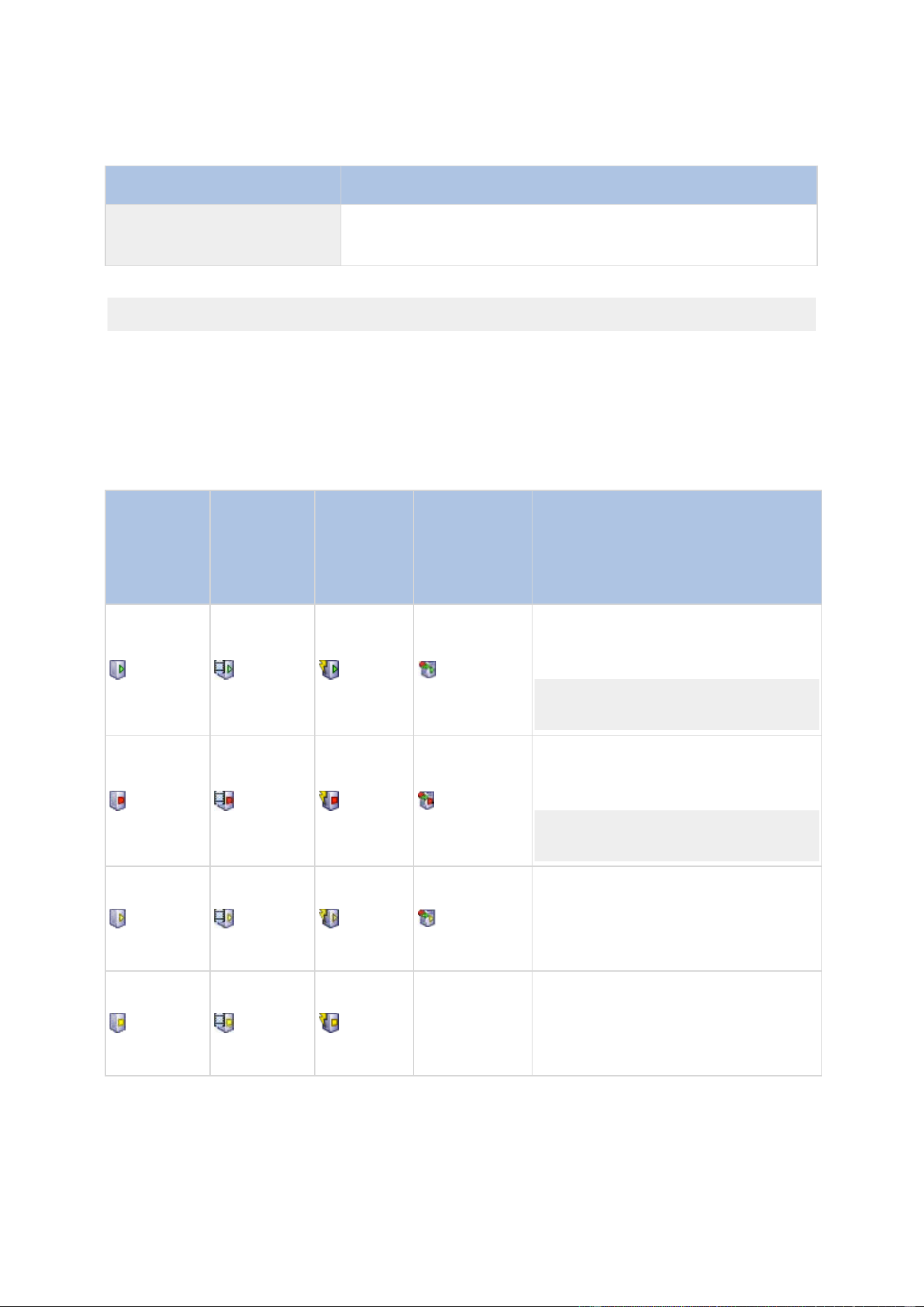
XProtect Professional VMS 2016 R3 - Administrator Manual
Advanced configuration
167
Service
Description
Milestone Mobile service
Manages the communication between the Recording Server and
mobile devices (such as smartphones and tablets) and between
the Recording Server and web browsers.
If you run a Custom installation, you can choose not to install the Event Server. If you do so, the
Event Server service is not seen in your Services overview.
About the tray icons
The tray icons in the table represent the possible states of the services running on Management
Server, Recording Server, Failover Recording Server, and Event Server. They are all visible on the
computers where the servers are installed, in the notification area:
Manage-
ment
Server
service
icon
Recording
Server
service
icon
Event
Server
service
icon
Failover
Recording
Server
service icon
Description
Running
Appears when a server service is
enabled and started.
If the Failover Recording Server service
is running, it can take over if the
standard recording servers fails.
Stopped
Appears when a server service has
stopped.
If the Failover Recording Server service
stops, it cannot take over if the
standard recording server fails.
Starting
Appears when a server service is in the
process of starting. Under normal
circumstances, the tray icon changes
after a short while to Running.
Stopping
Appears when a server service is in the
process of stopping. Under normal
circumstances, the tray icon changes
after a short while to Stopped.

XProtect Professional VMS 2016 R3 - Administrator Manual
Advanced configuration
168
Manage-
ment
Server
service
icon
Recording
Server
service
icon
Event
Server
service
icon
Failover
Recording
Server
service icon
Description
In indeterminate state
Appears when the server service is
initially loaded and until the first
information is received, upon which the
tray icon, under normal circumstances,
changes to Starting and afterwards to
Running.
Running offline
Typically appears when the Recording
Server or Failover recording service is
running but the Management Server
service is not.
Must be authorized by
administrator
Appears when the Recording Server
service is loaded for the first time.
Administrators authorize the recording
server through the Management Client:
Expand the Servers list, select the
Recording Server node and in the
Overview pane, right-click the
relevant recording server and select
Authorize Recording Server.
Start and stop services
On a system server, several services by default run in the background. If you need to, you can
start and stop each service separately:
1. Expand Advanced Configuration and select Services. This displays the status of each
service.
2. You can now stop each service by clicking the Stop button. When a service is stopped, the
button changes to Start, allowing you to start the service again when required.
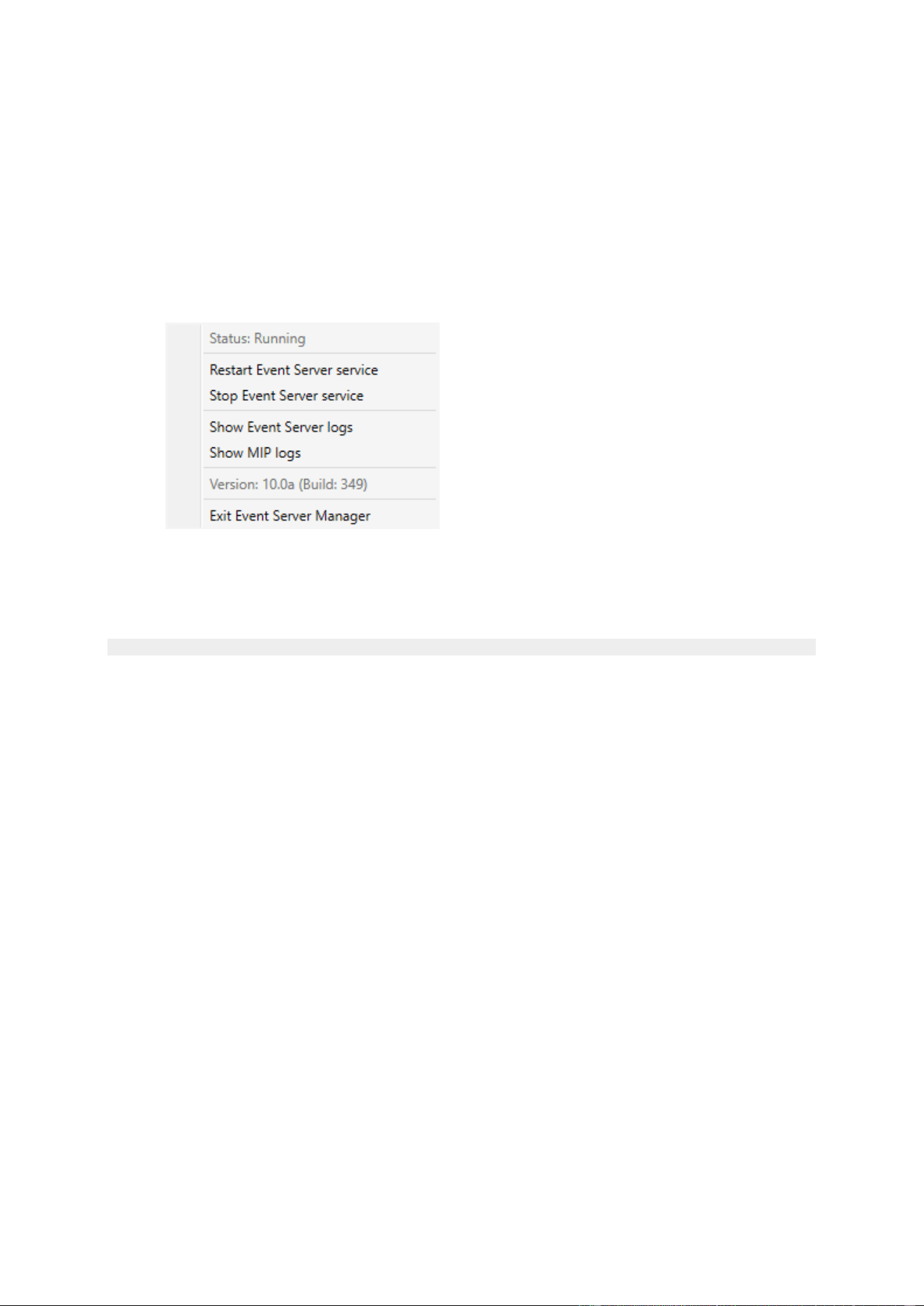
XProtect Professional VMS 2016 R3 - Administrator Manual
Advanced configuration
169
Start, stop, or restart the Event Server service
In the notification area, a tray icon indicates the state of the Event Server service, for example
Running. Through this icon, you can start, stop, or restart the Event Server service. If you stop
the service, parts of the system will not work, including events and alarms. However, you can still
view and record video. For more information, see Stopping the Event Server service (on page 169).
1. In the notification area, right-click the tray icon for the Event Server. A context-menu
appears.
2. If the service has stopped, click Start Event Server service to start it. The tray icon
changes to reflect the new state.
3. To restart or stop the service, click Restart Event Server service or Stop Event Server
service.
For more information about the tray icons, see About the tray icons (on page 167).
See also
Start or stop the Recording Server service
Stopping the Event Server service
When installing MIP plug-ins in the Event Server, first you must stop the Event Server service and
then, afterward, restart it. However, while the service is stopped, many areas of the VMS system
will not function:
No events or alarms are stored in the Event Server. However, system and device events
still trigger actions, for example start recording.
XProtect Access, XProtect LPR, and XProtect Transact do not work in the configuration or in
XProtect Smart Client.
Analytic events do not work.
Generic events work in XProtect Professional VMS, but are not stored in the Event Server.
No alarms are triggered.
In XProtect Smart Client, map view items, alarm list view items, and the Alarm Manager
workspace do not work.
MIP plug-ins in the Event Server cannot run.
MIP plug-ins in Management Application and XProtect Smart Client do not work correctly.
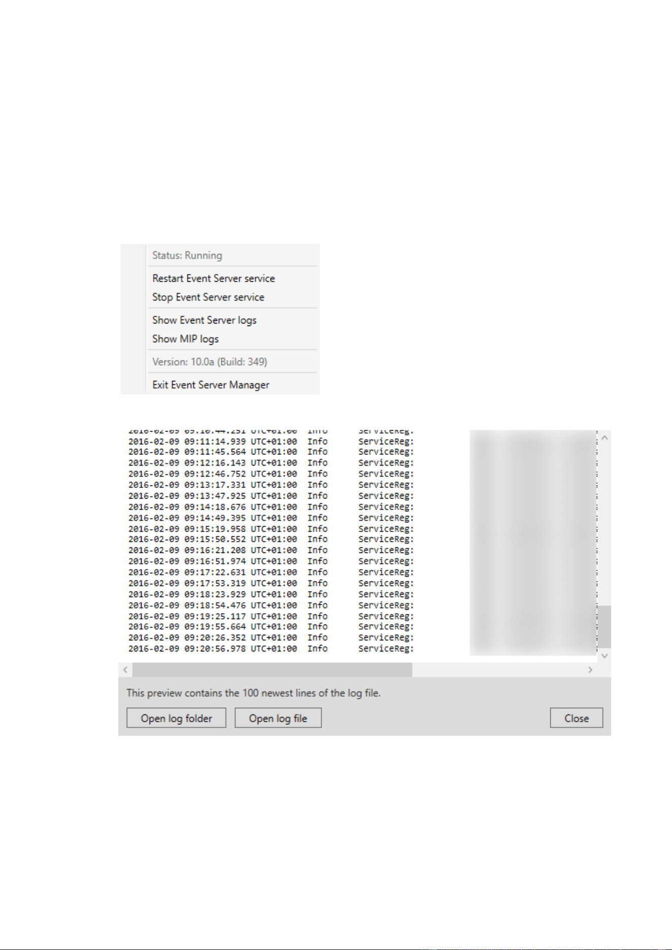
XProtect Professional VMS 2016 R3 - Administrator Manual
Advanced configuration
170
View Event Server or MIP logs
You can view time-stamped information about Event Server activities in the Event Server log.
Information about third party integrations is logged in the MIP log in a sub-folder in the Event
Server folder.
1. In the notification area, right-click the relevant tray icon. A context-menu appears.
2. To view the 100 most recent lines in the Event Server log, click Show Event Server Logs.
A log viewer appears.
1. To view the log file, click Open log file.
2. To open the log folder, click Open log folder.
3. To view the 100 most recent lines in the MIP log, go back to the context-menu and click
Show MIP logs. A log viewer is displayed.

XProtect Professional VMS 2016 R3 - Administrator Manual
Advanced configuration
171
If someone removes the log files from the log directory, the menu items are grayed out. To open
the log viewer, first you need to copy the log files back into one of these folders:
C:\ProgramData\Milestone\XProtect Event Server\logs or C:\ProgramData\Milestone\XProtect
Event Server\logs\MIPLogs.
Servers
LPR servers
LPR system overview
About XProtect LPR
Available functionality depends on the system you are using. See the Product comparison chart (on
page 11) for more information.
XProtect LPR offers video-based content analysis (VCA) and recognition of vehicle license plates
that interacts with your surveillance system and your XProtect Smart Client.
To read the characters on a plate, XProtect LPR uses optical character recognition on images aided
by specialized camera settings.
You can combine LPR (license plate recognition) with other surveillance features such as recording
and event-based activation of outputs.
Examples of events in XProtect LPR:
Trigger surveillance system recordings in a particular quality.
Activate alarms.
Match against positive/negative license plate match lists.
Open gates.
Switch on lights.
Push video of incidents to computer screens of particular security staff members.
Send mobile phone text messages.
With an event, you can activate alarms in XProtect Smart Client.
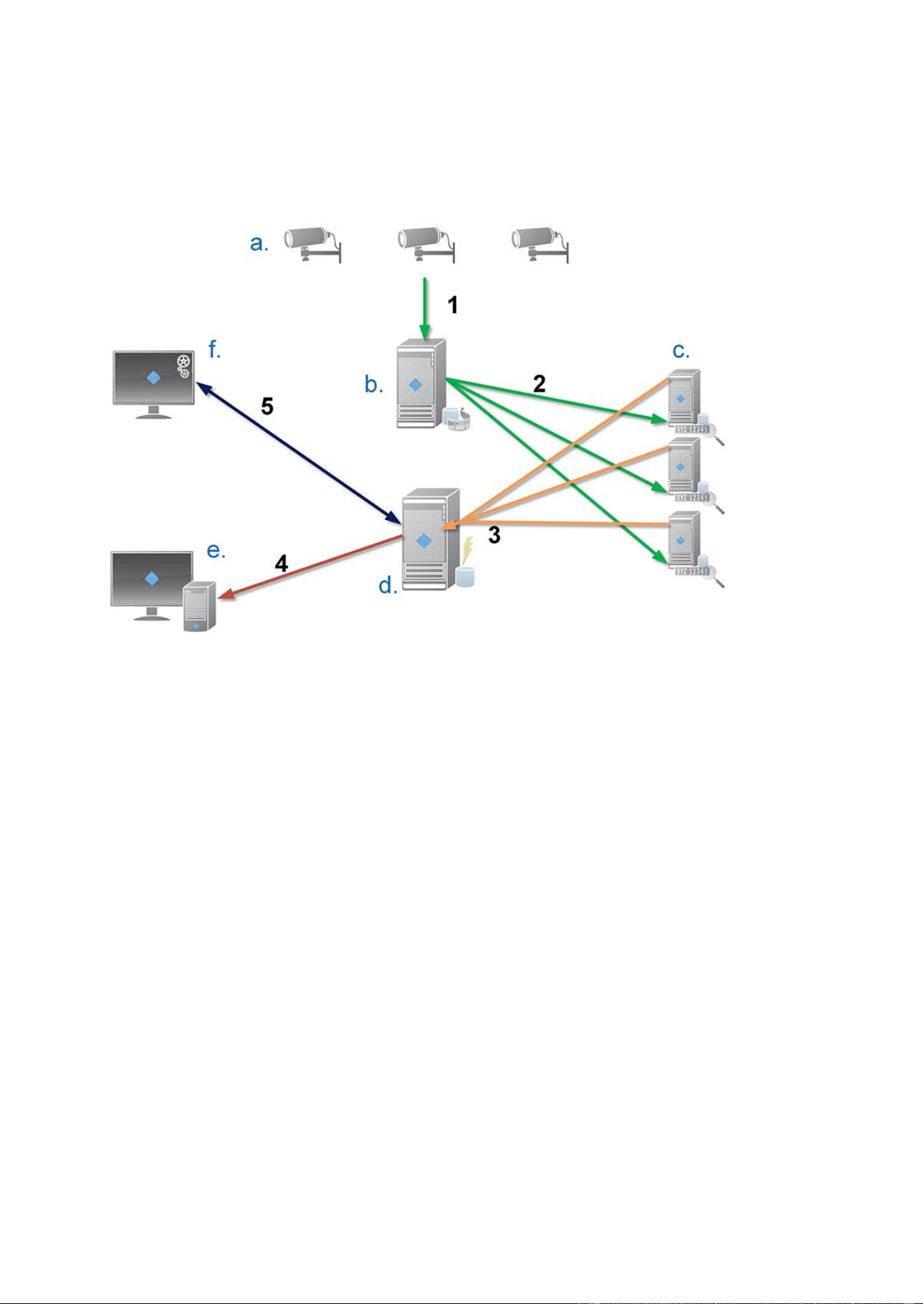
XProtect Professional VMS 2016 R3 - Administrator Manual
Advanced configuration
172
LPR system architecture
Basic data flow:
1. LPR cameras (a) send video to the recording server (b).
2. The recording server sends video to the LPR servers (c) to recognize license plates by comparing them
with the license plate characteristics in the installed country modules.
3. LPR servers send recognitions to the event server (d) to match with the license plate match lists.
4. The event server sends events and alarms to XProtect Smart Client (e) when there is a match.
5. The system administrator manages the entire LPR configuration, for example, setting up events,
alarms, and lists from the Management Application (f).
LPR server: The LPR server handles LPR video recorded by your surveillance system. It analyzes
the video and sends information to the event server that uses it for triggering the defined events
and alarms. Milestone recommends that you install the LPR server on a computer especially
allocated for this purpose.
LPR camera: The LPR camera captures video as any other camera, but some cameras are
dedicated for LPR use. The better suited camera you use, the more successful recognitions you will
get.
Country module: A country module is a set of rules that defines license plates of a certain type
and form as belonging to a certain country or region. It dictates plate and character specifics such
as color, height, spacing, and similar, which is used during the recognition process.
License plate match list: A license plate match list is a user-defined list that you create. License
plate match lists are collections of license plates that you want your system to treat in a special
way. Once you have specified a list, you can set up events to recognize license plates on these lists
and in this way trigger events and alarms.
Compatibility
XProtect LPR 2016 is compatible with the version 2014 SP3 or newer of:

XProtect Professional VMS 2016 R3 - Administrator Manual
Advanced configuration
173
XProtect Enterprise
XProtect Professional
XProtect Express
Milestone Husky™ M30
Milestone Husky™ M50.
XProtect LPR 2016 is compatible with Milestone Husky M30 and Milestone Husky M50, but these
products do not currently support the full functionality of XProtect LPR 2016.
Minimum system requirements
For information about the minimum system requirements for the various components of your
system, go to the Milestone website http://www.milestonesys.com/SystemRequirements.
Milestone recommends that you install the LPR server on a computer especially allocated for this
purpose.
LPR licenses
XProtect LPR requires the following LPR-related licenses:
A base license for XProtect LPR that covers an unlimited number of LPR servers.
One LPR camera license per LPR camera you want to use in XProtect LPR.
A LPR country module license for each country, state or region you need in your
XProtect LPR solution. Five LPR country module license are included with the XProtect
LPR base license. All country modules are automatically installed when you install your
XProtect LPR product. However, the installed modules are by default disabled and you
must enable the modules (see "Country modules tab" on page 196) that you want to
use. You can only enable as many country modules as you have LPR country module
licenses for.
Example: You have five LPR country module licenses and you have installed 10 country modules.
Once you have selected five country modules, you cannot select any more. You must clear some of
your selections before you can select other modules.
To find information about the current status of your licenses, see View LPR server information (on
page 187).
To buy additional LPR licenses or country modules, contact your vendor.
About preparing cameras for LPR
LPR differs from other kinds of video surveillance. Normally, you choose cameras based on their
ability to provide the best possible images for viewing by the human eye. When you choose
cameras for LPR, only the area where you expect to detect license plates is important. The more
clear and consistent you capture an image in that small area, the higher recognition rate you will
get.
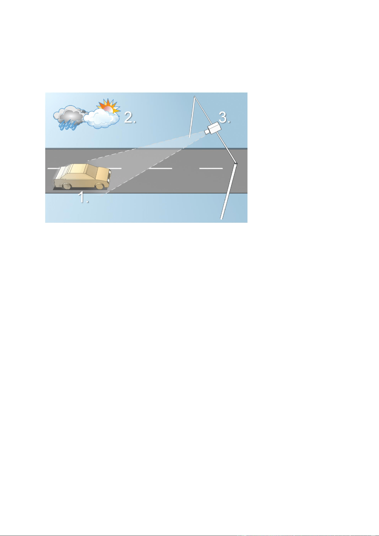
XProtect Professional VMS 2016 R3 - Administrator Manual
Advanced configuration
174
This section helps you to prepare cameras for license plate recognition, but it also introduces you
to important theories about cameras and lenses that are crucial to understand in order to get
optimal images.
Illustration of an LPR solution
Factors that influence your configuration of LPR:
1. Vehicle
Speed
Plate size and
position
2. Physical
surroundings
Lightning conditions
Weather
3. Camera
Exposure
Field of view
Shutter speed
Resolution
Positioning
It is important to take these factors into consideration as they have a critical influence on
successful license plate recognition. You must mount cameras and configure XProtect LPR in a way
that matches each specific environment. You cannot expect the product to run successfully without
configuration. A camera used for LPR has a CPU consumption that is about five times higher than a
normal camera. If a camera has not been set up correctly, it will highly affect the level of
successful recognitions and the CPU performance.
Read the following sections to learn about the factors that influence your LPR solution:
Positioning the camera (on page 175)
Camera angles (on page 176)
Plate width recommendations (on page 177)
Image resolution (on page 178)
Understanding camera exposure (on page 179)
Physical surroundings (on page 182)
Lens and shutter speed (on page 183)
Contrast (on page 184)

XProtect Professional VMS 2016 R3 - Administrator Manual
Advanced configuration
175
Unwanted camera features (on page 185)
Positioning the camera
When you mount cameras for LPR use, it is important to get a good, clear view of the area of
interest so the plate can be detected consistently. This ensures the best possible performance and
low risk of false detection:
The area should cover only the part of the image where the license plate is visible as the
vehicle moves in and out of the image.
Avoid to have objects that block the view path of the camera, such as pillars, barriers,
fences, gates.
Avoid irrelevant moving objects such as people, trees, or traffic in
If too many irrelevant items are included, they will interfere with the detection, and the LPR server
will use CPU resources on analyzing irrelevant items instead of license plates.
Left image shows a correct mounting without interference in the field of view. Right image shows an incorrect mounting. The
camera is mounted too low and with too much background 'noise' in the view.
To help you obtain a clear and undisturbed view, you can:
Mount the camera as close as possible to the area of interest.
Angle your camera.
Zoom. If you zoom, always use the camera's optical zoom.
Mount the camera so the license plate appears from the top of the image (or bottom if traffic is
driving away from the camera) instead of from the right or left side. In this way you make sure
that the recognition process of a license plate only starts when the whole plate is in the view:
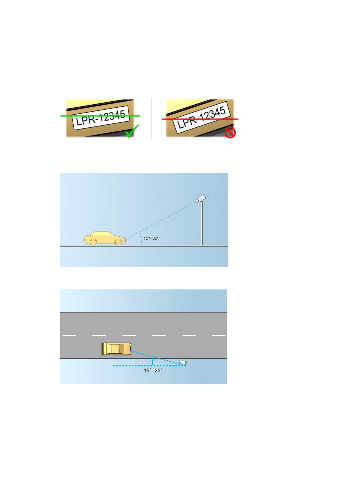
XProtect Professional VMS 2016 R3 - Administrator Manual
Advanced configuration
176
Camera angles
Single-line rule: Mount the camera so that you can draw a horizontal line that crosses
both the left and right edge of the license plate in the captured images. See the illustrations
below for correct and incorrect angles for recognition.
Vertical angle: The recommended vertical view angle of a camera used for LPR is between
15°-30°.
Horizontal angle: The recommended maximum horizontal view angle of a camera used for
LPR is between 15°-25°.
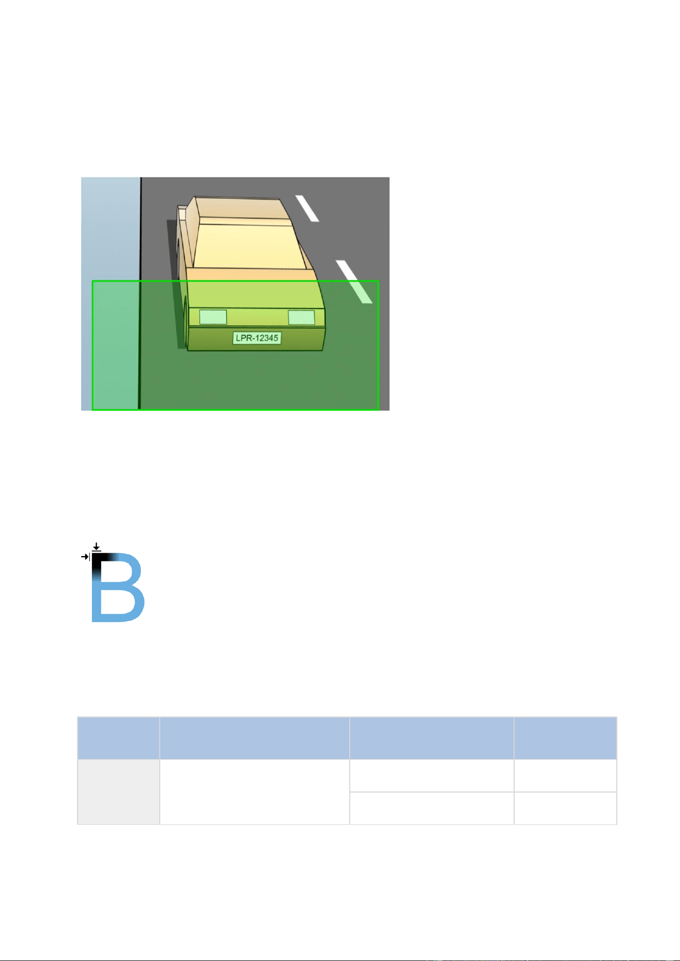
XProtect Professional VMS 2016 R3 - Administrator Manual
Advanced configuration
177
Plate width recommendations
Mount the camera so that the ideal snapshot of the license plate is captured when the license plate
is in the center or lower half of the image:
Take a snapshot and make sure that the requirements to stroke width and plate width as described
below are fulfilled. Use a standard graphics editor to measure the amount of pixels. When you start
the process of reaching the minimum plate width, begin with a low resolution on the camera, and
then work your way up in a higher resolution until you have the required plate width.
Stroke width
The term pixels per stroke is used to define a minimum requirement for fonts that should be
recognized. The following illustration outlines what is meant by stroke:
Because the thickness of strokes depends on country and plate style, measurements like pixels/cm
or pixels/inch are not used.
The resolution for best LPR performance should be at least 2.7 pixels/stroke.
Plate width
Plate type
Plate width
Setup
Minimum plate
width (pixels)
Single line
US plates
plate width 12 inches
stroke width around ¼ inches
vehicles stopped; no
interlacing
130
vehicles are moving;
interlaced
215
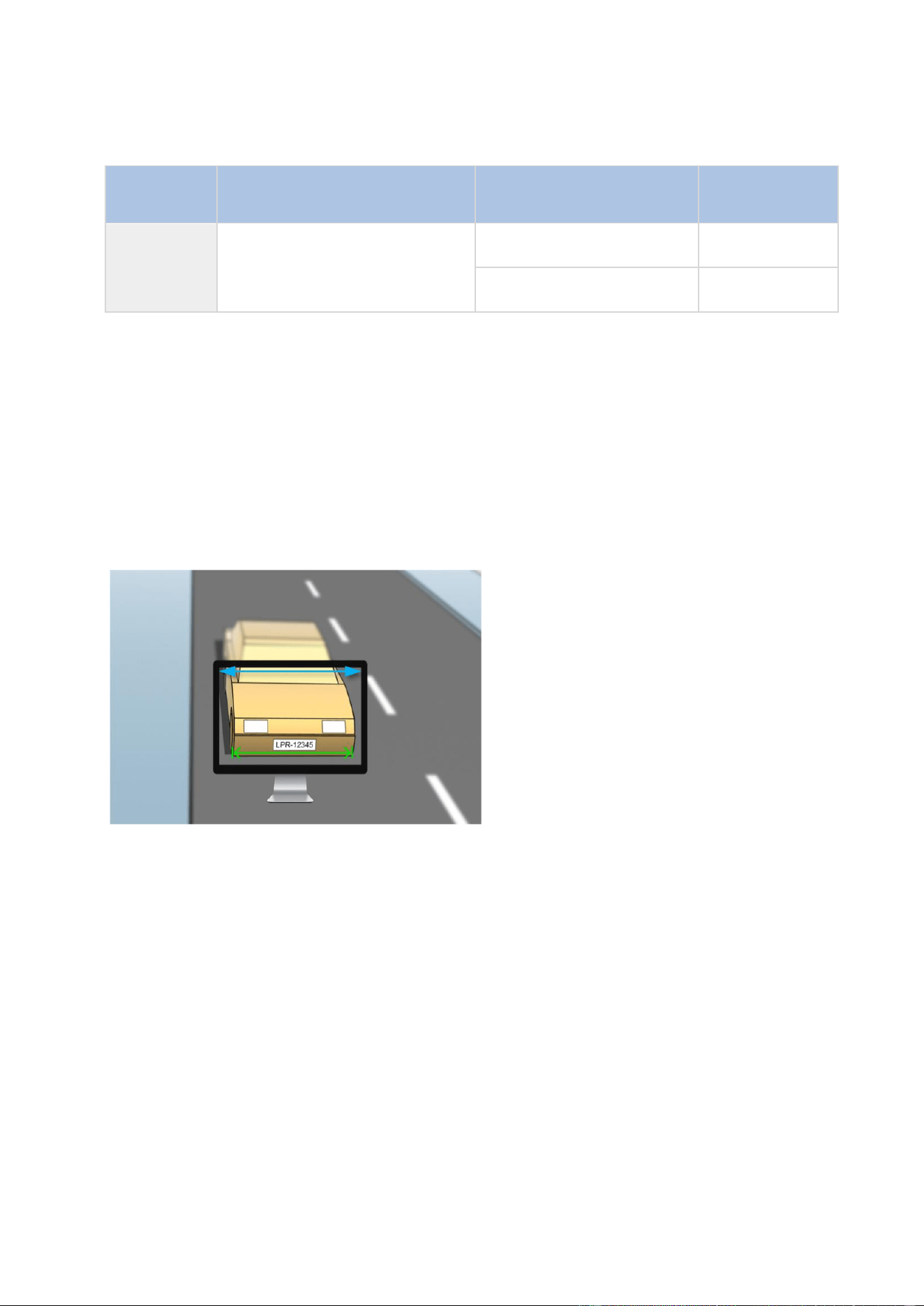
XProtect Professional VMS 2016 R3 - Administrator Manual
Advanced configuration
178
Plate type
Plate width
Setup
Minimum plate
width (pixels)
Single line
European
plates
plate width 52 cm
stroke width around 1 cm
vehicles stopped; no
interlacing
170
vehicles are moving;
interlaced
280
If vehicles are moving when recorded, and an interlaced camera is used, only a half of the image
can be used (only the even lines) for recognition compared with a camera configured for stopped
vehicles and no interlacing. This means that the resolution requirements are almost double as high.
Image resolution
Image quality and resolution is important for a successful license plate recognition. On the other
hand, if the video resolution is too high, the CPU might be overloaded with the risk of skipped or
faulty detections. The lower you can set the acceptable resolution, the better CPU-performance and
the higher detection rate you get.
In this example we explain how to do a simple image quality calculation and find a suitable
resolution for LPR. The calculation is based on the width of a car.
Example of a capture where we want to calculate a suitable resolution.
We estimate that the horizontal width is 200 cm/78 inches, as we assume the width of a standard
car is 177 cm/70 inches, and besides that we add ~10% for the extra space. You can also do a
physical measuring of the area of interest if you need to know the exact width.
The recommended resolution of the stroke thickness is 2.7 pixels/stroke, and the physical stroke
thickness is 1 cm for a European plate and 0.27 inches for a US plate. This gives the following
calculation:
Calculation for European plates in cm:
200 × 2.7 ÷ 1 = 540 pixels
Recommended resolution = VGA (640×480)
Calculation for US plates in inches:
78 × 2.7 ÷ 0.27 = 780 pixels
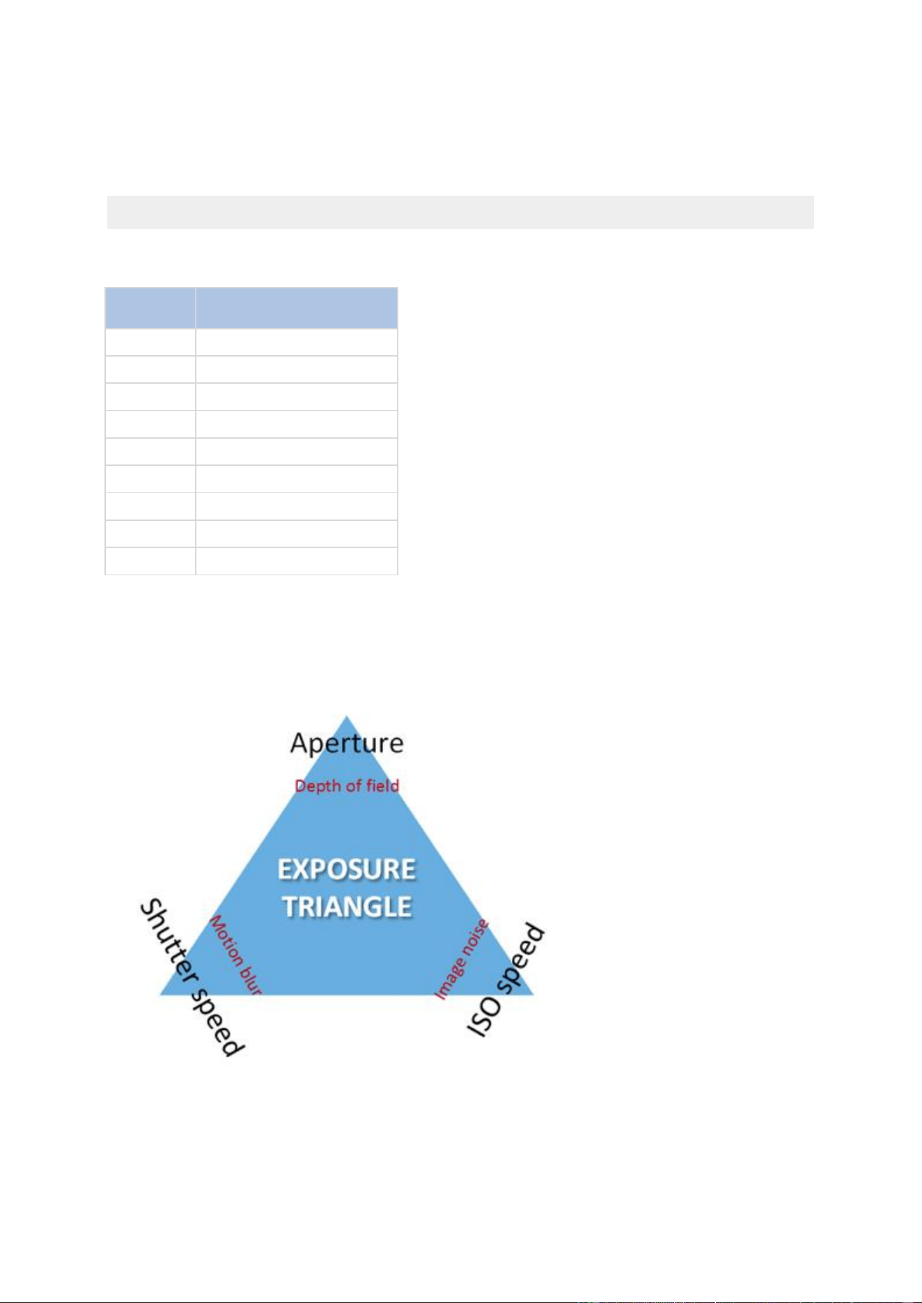
XProtect Professional VMS 2016 R3 - Administrator Manual
Advanced configuration
179
Recommended resolution = SVGA (800×600)
Because US plates use a font with a narrow stroke, a higher resolution is needed than for European
plates.
Common video resolutions
Name
Pixels (W×H)
QCIF
176×120
CIF
352×240
2CIF
704×240
VGA
640×480
4CIF
704×480
D1
720×576
SVGA
800×600
XGA
1024×768
720p
1280×1024
Understanding camera exposure
Camera exposure determines how light/dark and sharp/blurry an image appears when it has been
captured. This is determined by three camera settings: aperture, shutter speed, and ISO speed.
Understanding their use and interdependency can help you to set up the camera correctly for LPR.
Exposure triangle
You can use different combinations of the three settings to achieve the same exposure. The key is
to know which trade-offs to make, since each setting also influences the other image settings:

XProtect Professional VMS 2016 R3 - Administrator Manual
Advanced configuration
180
Camera settings
Controls...
Affects...
Aperture
The adjustable opening that
limits the amount of light to
enter the camera
Depth of field
Shutter speed
The duration of the exposure
Motion blur
ISO speed
The sensitivity of the
camera's sensor to a given
amount of light
Image noise
The next sections describe how each setting is specified, what it looks like, and how a given
camera exposure mode affects this combination:
Aperture settings
The aperture setting controls the amount of light that enters your camera from the lens. It is
specified in terms of an f-stop value, which can at times be counterintuitive, because the area of
the opening increases as the f-stop decreases.
Low f-stop value/wide aperture = shallow depth of field
High f-stop value/narrow aperture = large depth of field
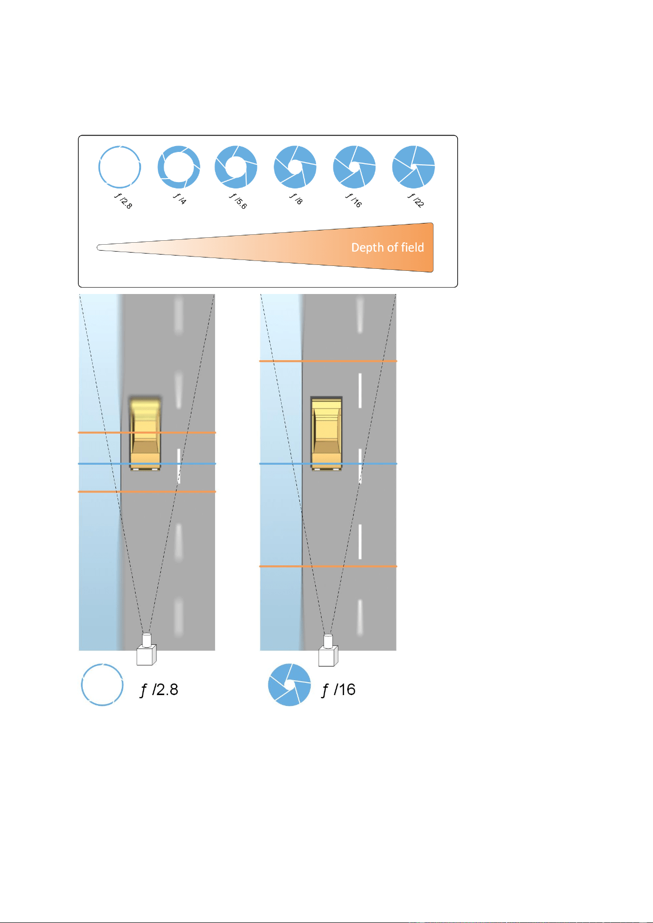
XProtect Professional VMS 2016 R3 - Administrator Manual
Advanced configuration
181
The example illustrates how the depth of field is affected by the f-stop value. The blue line indicates the focus point.
A high f-stop value makes it possible to have a longer distance where the license plate is in focus.
Good light conditions are important for sufficient exposure. If lightning conditions are insufficient,
the exposure time needs to be longer, which again increases the risk of getting blurry images.
A low f-stop value reduces the focus area and thereby the area used for recognition, but is suitable
for conditions with low light. If it is possible to ensure that vehicles are passing the focus area at a
low speed, a low f-stop value is suitable for a consistent recognition.
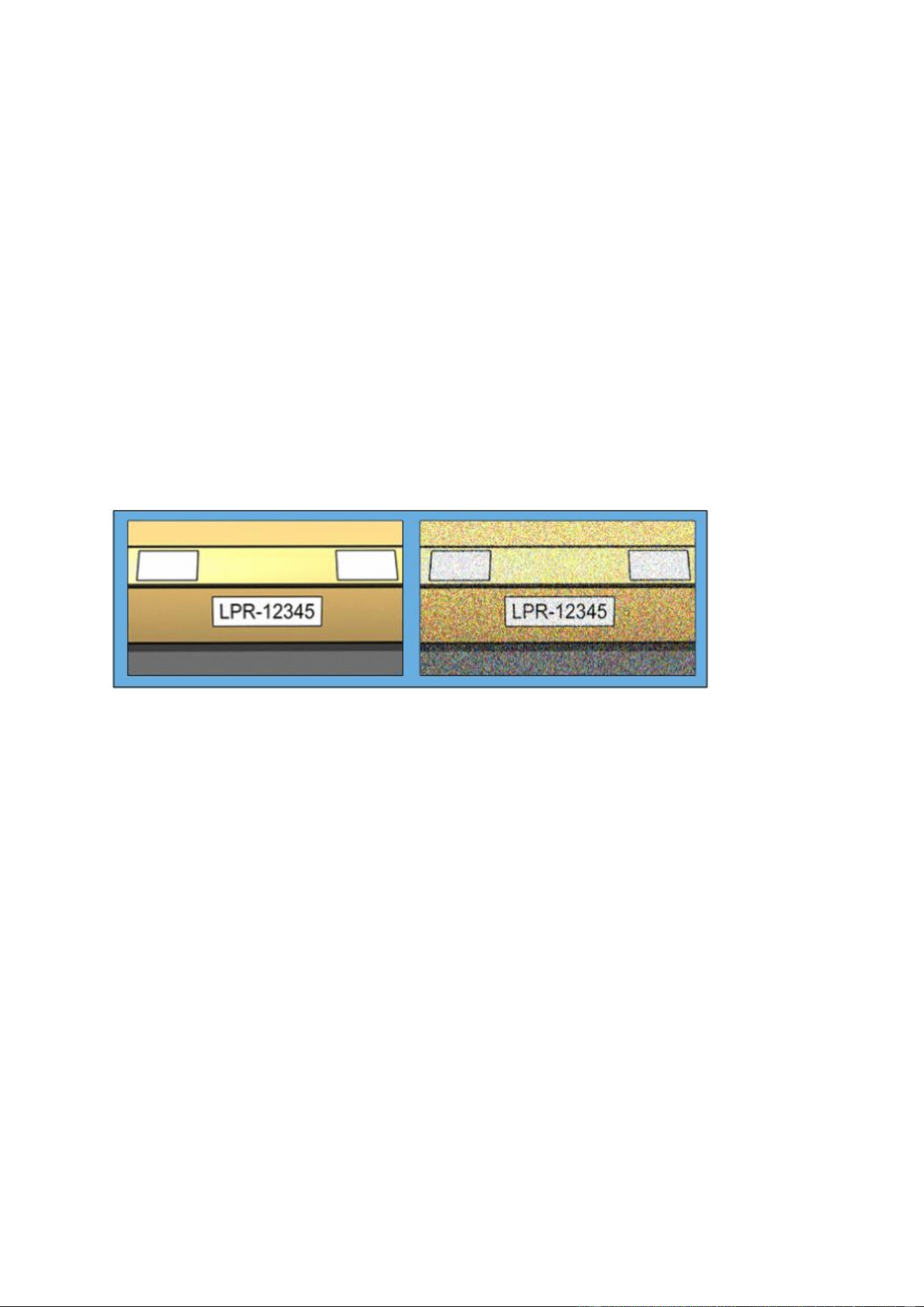
XProtect Professional VMS 2016 R3 - Administrator Manual
Advanced configuration
182
Shutter speed
A camera's shutter determines when the camera sensor is open or closed for incoming light from
the camera lens. The shutter speed refers to the duration when the shutter is open and light can
enter the camera. Shutter speed and exposure time refer to the same concept, and a faster shutter
speed means a shorter exposure time.
Motion blur is undesired for license plate recognition and surveillance. In many occasions vehicles
are in motion while license plates are detected which makes a correct shutter speed an important
factor. The rule of thumb is to keep the shutter speed high enough to avoid motion blur, but not
too high as this may cause under-exposed images depending on light and aperture.
ISO speed
The ISO speed determines how sensitive the camera is to incoming light. Similar to shutter speed,
it also correlates 1:1 with how much the exposure increases or decreases. However, unlike
aperture and shutter speed, a lower ISO speed is in general desirable, since higher ISO speeds
dramatically increase image noise. As a result, ISO speed is usually only increased from its
minimum value if the desired image quality is not obtainable by modifying the aperture and shutter
speed settings solely.
Example of low and high ISO speed images. High ISO speed on the right image affects the level of image noise negatively.
Common ISO speeds include 100, 200, 400 and 800, although many cameras also permit lower or
higher values. With digital single-lens reflex (DSLR) cameras, a range of 50-800 (or higher) is
often acceptable.
Physical surroundings
When you mount and use cameras for LPR, note the following factors related to the surroundings:
Much light: Too much light in the surroundings can lead to overexposure or smear.
Overexposure is when images are exposed to too much light, resulting in a burnt-out
and overly white appearance. To avoid overexposure, Milestone recommends that you
use a camera with a high dynamic range and/or use an auto-iris lens. Iris is the
adjustable aperture. For that reason, iris has a significant effect on the exposure of
images.
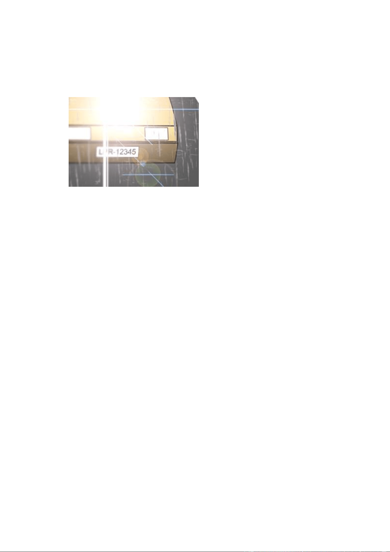
XProtect Professional VMS 2016 R3 - Administrator Manual
Advanced configuration
183
Smear is an effect that leads to unwanted light vertical lines in images. It is often
caused by slight imperfections in the cameras’ charge-coupled device (CCD)
imagers. The CCS imagers are the sensors used to digitally create the images.
License plate image with smear because of overexposure
Little light: Too little light in the surroundings or too little external lighting can lead to
underexposure.
Underexposure is when images are exposed to too little light, resulting in a dark
image with hardly any contrast (on page 184). When auto-gain (see "Unwanted camera
features" on page 185) cannot be disabled or when you are not able to configure a
maximum allowed shutter time (see "Lens and shutter speed" on page 183) for
capturing moving vehicles, too little light will initially lead to gain noise and motion blur
in the images, and ultimately to underexposure. To avoid underexposure, use sufficient
external lighting and/or use a camera that has sufficient sensitivity in low-light
surroundings without using gain.
Infrared: Another way to overcome difficult lighting conditions is to use artificial infrared
lighting combined with an infrared-sensitive camera with an infrared pass filter. Retro-
reflective license plates are particularly suitable for use with infrared lighting.
Retro-reflectivity is achieved by covering surfaces with a special reflective material
which sends a large portion of the light from a light source straight back along the path
it came from. Retro-reflective objects appear to shine much more brightly than other
objects. This means that at night they can be seen clearly from considerable distances.
Retro-reflectivity is frequently used for road signs, and is also used for different types of
license plates.
Weather: Snow or very bright sunlight may for example require special configuration of
cameras.
Plate condition: Vehicles may have damaged or dirty license plates. Sometimes this is
done deliberately in an attempt to avoid recognition.
Lens and shutter speed
When configuring cameras’ lenses and shutter speeds for LPR, note the following:
Focus: Always make sure the license plate is in focus.
Auto-iris: If using an auto-iris lens, always set the focus with the aperture as open as
possible. In order to make the aperture open, you can use neutral density (ND) filters or—if

XProtect Professional VMS 2016 R3 - Administrator Manual
Advanced configuration
184
the camera supports manual configuration of the shutter time—the shutter time can be set
to a very short time.
Neutral Density (ND) filters or gray filters basically reduce the amount of light coming
into a camera. They work as "sunglasses" for the camera. ND filters affect the exposure
of images (see "Understanding camera exposure" on page 179).
Infrared: If using an infrared light source, focus may change when switching between
visible light and infrared light. You can avoid the change in focus by using an infrared
compensated lens, or by using an infrared pass filter. Note that if you use an infrared pass
filter, an infrared light source is required—also during daytime.
Vehicle speed: When vehicles are moving, cameras’ shutter time should be short enough
to avoid motion blur. A formula for calculating the longest suitable shutter time is:
Vehicle speed in km/h: Shutter time in seconds = 1 second / (11 × max vehicle
speed in kilometers per hour)
Vehicle speed in mph: Shutter time in seconds = 1 second / (18 × max vehicle speed
in miles per hour)
where / denotes "divided by" and × denotes "multiplied by."
The following table provides guidelines for recommended camera shutter speeds for different
vehicle speeds:
Shutter
time
in seconds
Max. vehicle
speed in
kilometers
per hour
Max. vehicle
speed
in miles per
hour
1/50
4
2
1/100
9
5
1/200
18
11
1/250
22
13
1/500
45
27
1/750
68
41
1/1000
90
55
1/1500
136
83
1/2000
181
111
1/3000
272
166
1/4000
363
222
Contrast
When you determine the right contrast for your LPR camera, consider the difference in gray value
(when images are converted to 8-bit grayscale) between the license plate’s characters and the
license plate’s background color:
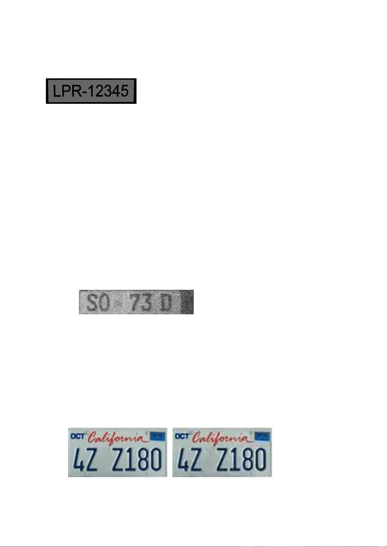
XProtect Professional VMS 2016 R3 - Administrator Manual
Advanced configuration
185
Good contrast
Acceptable contrast; recognition is still possible
Pixels in an 8-bit grayscale image can have color values ranging from 0 to 255, where grayscale
value 0 is absolute black and 255 is absolute white. When you convert your input image to an 8-bit
grayscale image, the minimum pixel value difference between a pixel in the text and a pixel in the
background should be at least 15.
Note that noise in the image (see "Unwanted camera features" on page 185), the use of
compression (see "Unwanted camera features" on page 185), the light conditions, and similar can
make it difficult to determine the colors of a license plate’s characters and background.
Unwanted camera features
When you configure cameras for LPR, note the following:
Automatic gain adjustment: One of the most common types of image interference
caused by cameras is gain noise.
Gain is basically the way that a camera captures a picture of a scene and distributes
light into it. If light is not distributed optimally in the image, the result is gain noise.
Controlling gain requires that complex algorithms are applied, and many cameras have
features for automatically adjusting gain. Unfortunately, such features are rarely helpful
in connection with LPR. Milestone recommends that you configure your cameras’ auto-
gain functionality to be as low as possible. Alternatively, disable the cameras’ auto-gain
functionality.
License plate image with gain noise
In dark surroundings, you can avoid gain noise by installing sufficient external lighting.
Automatic enhancement: Some cameras use contour, edge or contrast enhancement
algorithms to make images look better to the human eye. Such algorithms can interfere
with the algorithms used in the LPR process. Milestone recommends that you disable the
cameras’ contour, edge and contrast enhancement algorithms whenever possible.
Automatic compression: High compression rates can have a negative influence on the
quality of license plate images. When a high compression rate is used, more resolution (see
"Plate width recommendations" on page 177) is required in order to achieve optimal LPR
performance. If a low JPEG compression is used, the negative impact on LPR is very low, as
long as the images are saved with a JPEG quality level of 80% or above, and images have
normal resolution, contrast and focus as well as a low noise level.

XProtect Professional VMS 2016 R3 - Administrator Manual
Advanced configuration
186
Left: License plate image saved with a JPEG quality level of 80% (i.e. low compression); acceptable
Right: License plate image saved with a JPEG quality level of 50% (i.e. high compression);
unacceptable
LPR installation
Install XProtect LPR
To run XProtect LPR, you must install:
At least one LPR server.
The LPR plug-in on all computers that run the Management Application and the event
server.
Make sure that the user selected for running the LPR Server service can access the
management server.
Milestone recommends that you do not install the LPR server on the same computer as your
management server or recording servers.
Start installation:
1. Go to the download page on the Milestone website
http://www.milestonesys.com/downloads.
2. Download the two installers:
Milestone
XProtect LPR Plug-in installer to all computers that run the Management
Application and the event server.
Milestone XProtect LPR Server installer to all computers allocated for this purpose. You
can also create virtual servers for LPR on one computer.
3. First, run all the Milestone XProtect LPR Plug-in installers.
4. Then, run the Milestone XProtect LPR Server installer(s).
During installation, specify the IP address or hostname of the management server for
XProtect Advanced VMS products or the image server for XProtect Professional VMS
products including the domain user name and password of a user account that has
administrator rights to the surveillance system.
5. Launch the Management Application.
In the Management Application's navigation pane, your Management Application
automatically lists the installed LPR servers in the LPR Servers list.
6. Make sure that you have the necessary licenses (see "LPR licenses" on page 173).
7. All country modules are automatically installed when you install your XProtect LPR product.
However, the installed modules are by default disabled and you must enable the modules
(see "Country modules tab" on page 196) that you want to use. You can only enable as
many country modules as you have LPR country module licenses for.
You cannot add LPR servers from the Management Application.

XProtect Professional VMS 2016 R3 - Administrator Manual
Advanced configuration
187
If you need to install more LPR servers after the initial installation, run the Milestone XProtect LPR
Server installer on these servers.
If an antivirus program is installed on a computer running XProtect software, it is important that
you exclude the C:\ProgramData\Milestone\XProtect LPR folder. Without implementing this
exception, virus scanning uses a considerable amount of system resources and the scanning
process can temporarily lock files.
Upgrade XProtect LPR
To upgrade XProtect LPR, you follow the same steps as for installation (see "Install XProtect LPR"
on page 186).
If you upgrade from XProtect LPR 1.0 to XProtect LPR 2016, some recognition settings are not
compatible with those from the previous configuration. To apply the new settings, you must save
your configuration. The settings that previously allowed you to flip, rotate and invert the colors of
the video have been removed. If you still need these functions, you must change the settings on
the cameras themselves.
LPR configuration
View LPR server information
To check the state of your LPR servers:
1. In the Management Application's navigation pane, expand Servers and select LPR
servers. Go to the Overview pane.
The LPR server information window opens with a summary of the server status:
Name
Host name
Status
2. Select the relevant LPR server and review all details for this server (see "LPR server
information properties" on page 187).
LPR server information properties
Field
Description
Name
Here you can change the name of the LPR server.
Host name
Shows the LPR server host name.
The first part of the name of the LPR server consists of the name
of the host computer for your LPR server installation. Example:
MYHOST.domainname.country.

XProtect Professional VMS 2016 R3 - Administrator Manual
Advanced configuration
188
Field
Description
Status
Shows the status of the LPR server.
If the server has just been added, the status is:
No LPR cameras configured.
If the system is running without problems, the status is:
All LPR cameras are running.
Alternatively, the system returns:
Service not responding.
Not connected to surveillance system.
Service not running.
Event Server not connected.
Unknown error.
X of Y LPR cameras running.
Service up time
Shows the up time since the LPR server was last down and the
LPR server service started.
Computer CPU usage
Shows the current CPU usage on the entire computer with the
LPR server(s) installed.
Memory available
Shows how much memory is available on the LPR server.
Recognized license plates
Shows the number of license plates that the LPR server has
recognized in this session.
LPR cameras
Shows a list of enabled LPR cameras that run on the LPR server
and their status.
LPR cameras available
Based on your license, this number shows how many additional
LPR cameras you are allowed to add and use on all your LPR
servers in total.
Country modules available
Based on your license, this number shows how many additional
country modules you are allowed to use on all your LPR servers in
total. It also lists the number of country modules already in use.
Configuring cameras for LPR
Prerequisites in the Management Application
Once cameras have been mounted and added in the Management Application, adjust each
camera's settings so that they match the requirements for LPR. You adjust camera settings on the
properties tabs for each camera device.
For the relevant cameras Milestone recommends to:
Set the video codec to JPEG.
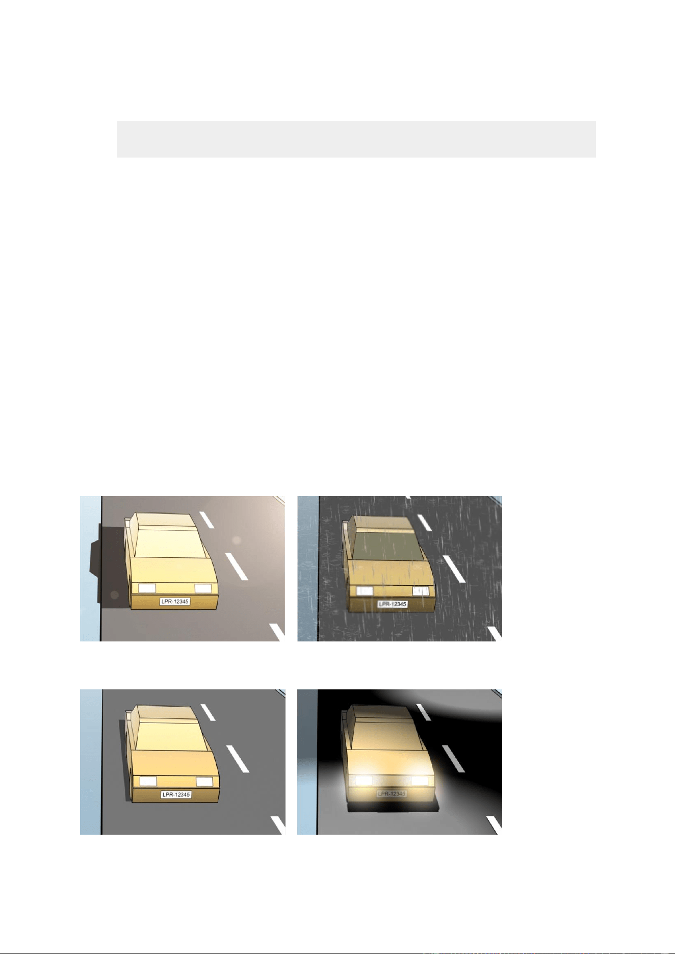
XProtect Professional VMS 2016 R3 - Administrator Manual
Advanced configuration
189
Note that if you use H.264 or H.265 codec, only key frames are supported. This is usually
only one frame per second which is not enough for LPR. For higher frame rates, always use
a JPEG codec.
Specify a frame rate of four frames per second.
Avoid compression, so set a fine quality.
If possible, specify a resolution below one megapixel.
If possible, keep automatic sharpness at a low level.
To learn about LPR fundamentals, make yourself familiar with the information in About preparing
cameras for LPR (on page 173).
About snapshots
The system uses snapshots to optimize the configuration automatically and to visualize the effect
of the recognition settings as they are applied.
You need to provide at least one valid snapshot in order to complete the initial configuration of a
camera.
As a guideline, capture snapshots of vehicles in the real physical surroundings and conditions, in
which you want to be able to recognize license plates.
The list below illustrates examples of the situations that you should consider when you capture and
select snapshots. Not all may be applicable for your surroundings.
Milestone recommends that you select minimum 5-10 snapshots that represent typical conditions
of:
The weather; for example sunlight and rain
The light; for example daylight and nighttime

XProtect Professional VMS 2016 R3 - Administrator Manual
Advanced configuration
190
Vehicle types; to define the top and bottom of the recognition area
Position in the lane; to define the left and right of the recognition area
Distance to the car; to define the area where LPR analyzes license plates
Add LPR camera
To configure cameras for LPR, you initially run the Add LPR camera wizard. The wizard takes you
through the main configuration steps and automatically optimizes the configuration.
To run the wizard:

XProtect Professional VMS 2016 R3 - Administrator Manual
Advanced configuration
191
1. In the Management Application's navigation pane, expand Servers, expand LPR servers,
and select LPR camera.
2. Go to the Overview pane. Right-click LPR camera.
3. From the menu that appears, select Add LPR camera and follow the instructions in the
wizard:
Select the camera you want to configure for LPR.
Select which country modules you want to use with your LPR camera (see "Country
modules tab" on page 196).
Select snapshots to use for validating the configuration (see "About snapshots" on page
189).
Validate the result of the snapshot analysis (see "Validate configuration" on page 198).
Select which license plate match lists to use (see "About license plate match lists" on
page 199). Choose the default selection, if you have not yet created any lists.
4. On the last page, click Close.
The LPR camera appears in the Management Application and based on your selections, the
system has optimized the recognition settings for the camera (see "Recognition settings
tab" on page 192).
5. Select the camera you have added and review its settings. You only need to change the
configuration if the system does not recognize license plates as well as expected.
6. In the Recognition settings tab, click Validate configuration (on page 198).
Adjust settings for your LPR camera
The system automatically optimized the configuration of your LPR camera, when you added the LPR
camera with the Add LPR camera wizard. If you want to make changes to the initial configuration,
you can:
Change the name of the server or change server (see "Info tab" on page 191).
Adjust and validate the recognition settings (see "Recognition settings tab" on page 192).
Add more license plate match lists (see "Match lists tab" on page 196).
Enable additional country modules (see "Country modules tab" on page 196).
Info tab
This tab provides information about the selected camera:
Name
Description
Enable
LPR cameras are by default enabled after the initial configuration.
Disable any camera that is not used in connection with LPR.
Disabling an LPR camera does not stop it from performing normal
recording in the surveillance system.
Camera
Shows the name of the selected camera as it appears in the
XProtect Management Application and the clients.
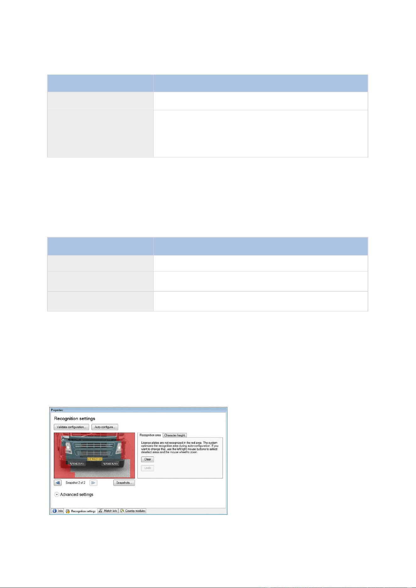
XProtect Professional VMS 2016 R3 - Administrator Manual
Advanced configuration
192
Name
Description
Description
Use this field to enter a description (optional).
Change Server
Click to change LPR server.
Changing the LPR server can be a good idea if you need to load
balance. For example, if the CPU load is too high on an LPR
server, Milestone recommends that you move one or more LPR
cameras to another LPR server.
Recognition settings tab
Recognition settings are auto-configured and optimized by the system during the initial
configuration of your LPR camera, primarily based on the snapshots you have provided.
Action buttons
Use these buttons to update and validate your settings after the initial configuration.
Name
Description
Snapshots
Add or delete snapshots (see "Select snapshots" on page 197).
Validate configuration
Test that license plates are recognized as expected (see "Validate
configuration" on page 198).
Auto-configure
Disregard manual changes and optimize settings (see "Auto-
configure" on page 198).
Recognition area
The system optimizes the recognition area during auto-configuration, but you can change it
manually.
To ensure the best possible performance and low risk of false detection, Milestone recommends
that you always select a clearly defined and "well-trimmed" recognition area. The area should cover
only the part of the image where the license plate is visible as the vehicle moves in and out of the
image. Avoid irrelevant moving objects such as people, trees, or traffic in the recognition area (see
"Positioning the camera" on page 175).
License plates are not recognized in the red area.
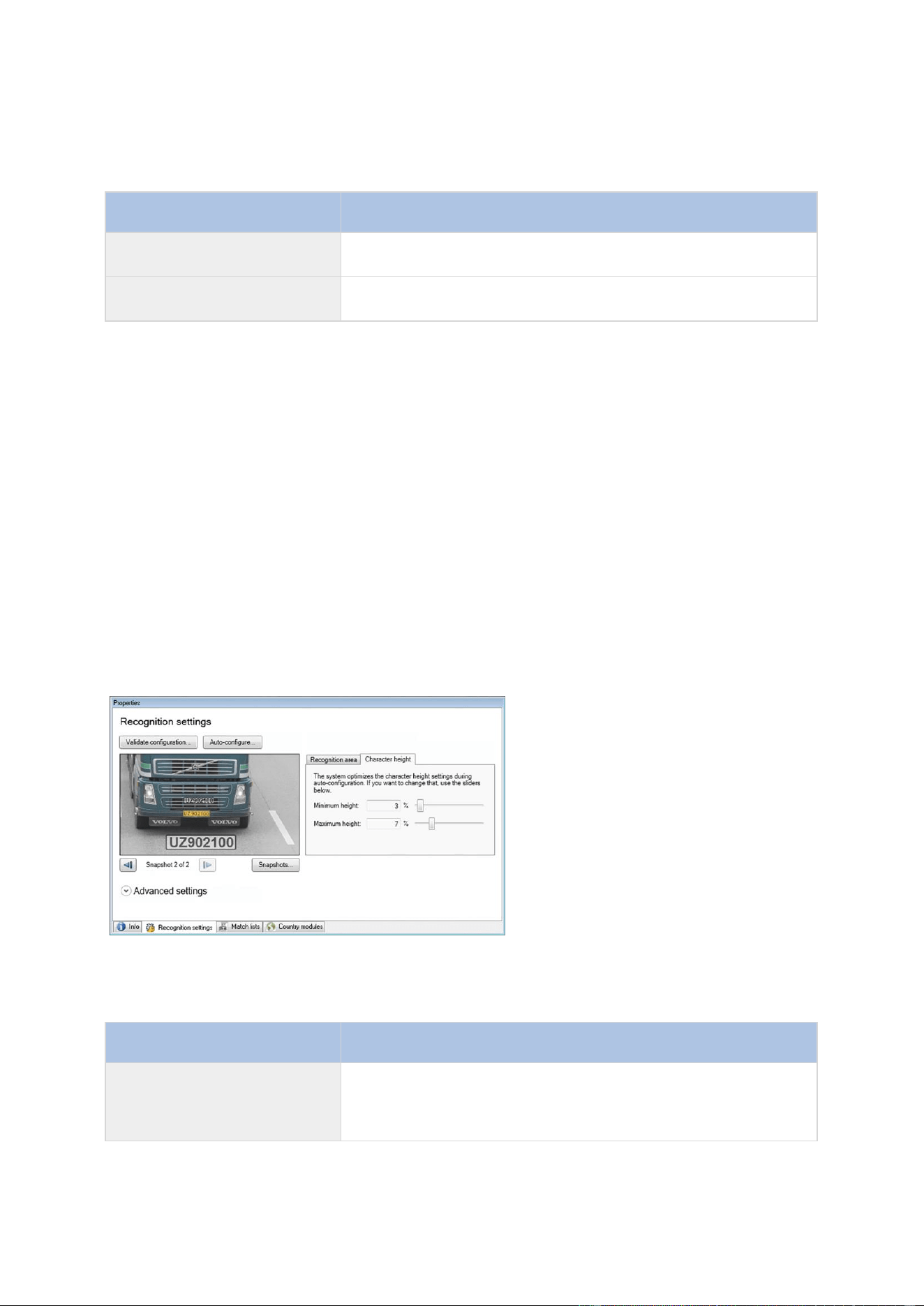
XProtect Professional VMS 2016 R3 - Administrator Manual
Advanced configuration
193
When you specify an area of recognition, you have the following options:
Name
Description
Clear
Click to remove all selections, so no areas are used for LPR.
Select new areas.
Undo
Click to revert to your latest saved configuration of the
recognition area.
When you have changed the settings for your LPR camera, validate your configuration (see
"Validate configuration" on page 198) to see if the system recognizes license plates as well as
expected.
Character height
The system optimizes the character height during auto-configuration, but you can change it
manually.
You define the minimum and maximum height of the license plate characters (in percent). Select
character heights as close as possible to the height of the characters in the real license plate.
These character settings influence the recognition process as they partly determine the recognition
time. As a rule, the larger the difference between the minimum and the maximum character
height:
The more complex the LPR process is.
The higher the CPU load is.
The longer you have to wait for the results.
The overlay in the snapshot displays the currently defined character height setting. The overlay
grows and shrinks proportionally with the character height settings to the right. For easy
comparison, you can drag the overlay on top of the real license plate in the snapshot. If needed,
use the mouse wheel to zoom.
Name
Description
Minimum height
Use the sliders to set the minimum character height to be
included in a recognition process. The system will not start the
recognition process on license plates that contain characters
below the specified value.
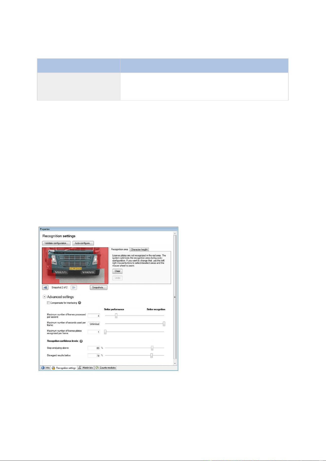
XProtect Professional VMS 2016 R3 - Administrator Manual
Advanced configuration
194
Name
Description
Maximum height
Use the sliders to set the maximum character height to be
included in a recognition process. The system will not start the
recognition process on license plates that contain characters
above the specified value.
When you have changed the settings for your LPR camera, validate your configuration (see
"Validate configuration" on page 198) to see if the system recognizes license plates as well as
expected.
Advanced settings
The system optimizes the advanced settings during auto-configuration, but you can change them
manually.
The recognition process can be divided into two steps: finding the plate(s) and recognizing the
characters on the plates. The advanced settings allow you to define a trade-off between processing
speed and recognition quality.
The general rule is that high recognition quality:
needs the highest computational effort,
results in higher CPU load,
requires more time to return results.
By adjusting the advanced settings, you define the trade-off. The recognition process stops if any
of the stop criteria are met and returns the license plate it recognized at that point.

XProtect Professional VMS 2016 R3 - Administrator Manual
Advanced configuration
195
Name
Description
Compensate for interlacing
In case your LPR camera sends interlaced video and you observe
combing effects in the de-interlaced image in LPR, you can enable
this function. This may improve the quality of the image and
thereby your recognition results.
Maximum number of frames
processed per second
Specifies a limit to the number of frames that your LPR solution
processes per second. If you keep the number of frames low for
LPR processes, you can apply a higher frame rate on the camera
for recording without adding unnecessary load to the LPR Server.
Unlimited means that you have not defined a stop criterion for
this setting.
Maximum number of
seconds used per frame
Specifies a limit to the number of seconds that your LPR solution
is allowed to spend on recognition of one frame. If adjusted,
recommended value is 200 ms per frame.
Unlimited means that you have not defined a stop criterion for
this setting.
Maximum number of license
plates recognized per frame
Specifies a limit to the number of recognized license plates
returned per frame. Do only change this setting if really needed,
for example, if you are detecting multiple lanes with one LPR
camera.
Unlimited means that you have not defined a stop criterion for
this setting.
Stop analyzing above
Specifies a minimum confidence level (in percent). The
recognition process continues until the system can return a
license plate reading with a confidence level equal to or higher
than the specified value.
Disregard results below
The system rejects license plate readings with a confidence level
equal to or lower than the specified value.
As a rule, the smaller you keep the difference between the Stop
analyzing above and Disregard results below values, the
lower is the CPU load and the system returns recognition results
faster.
When you have changed the settings for your LPR camera, validate your configuration (see
"Validate configuration" on page 198) to see if the system recognizes license plates as well as
expected.
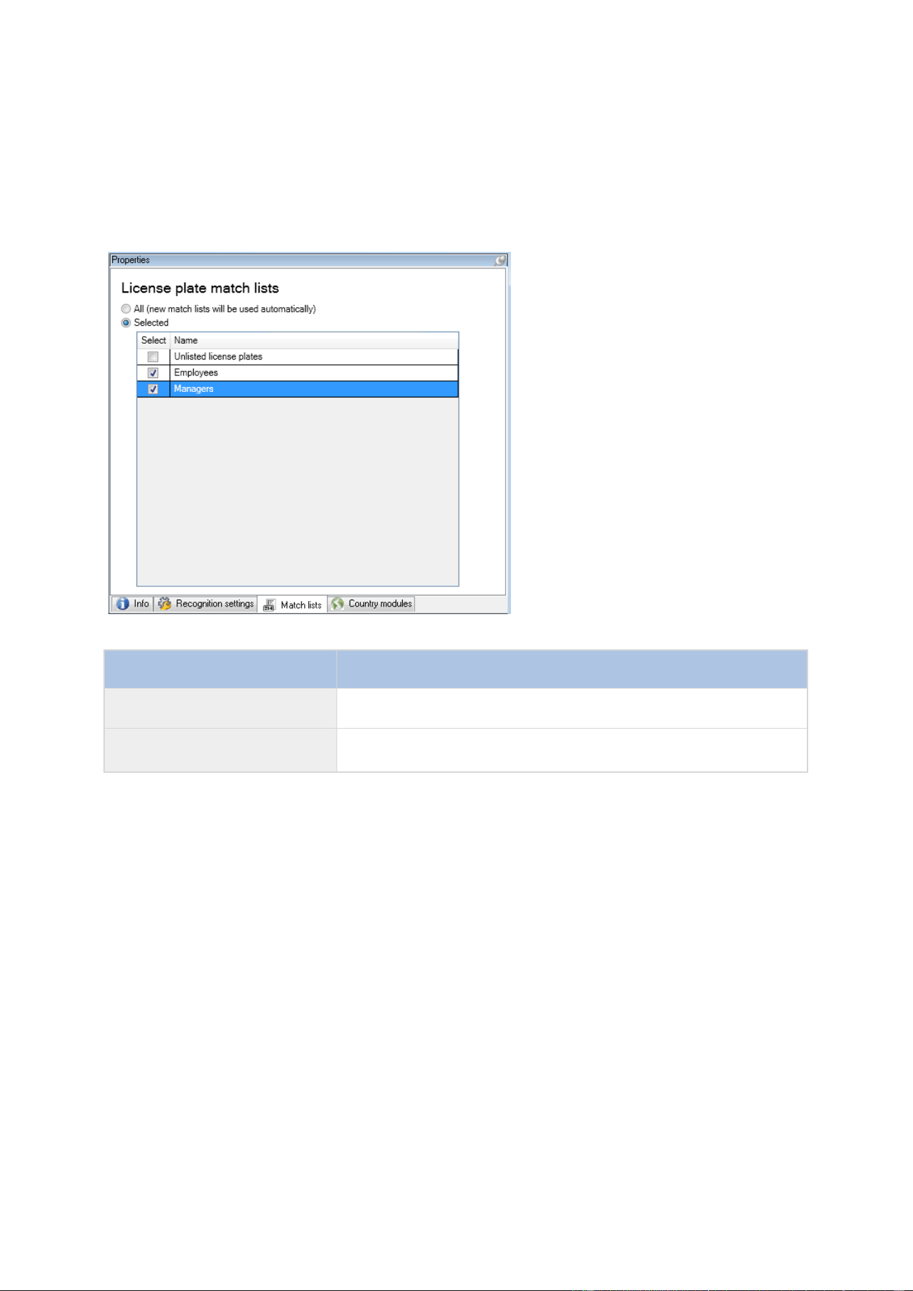
XProtect Professional VMS 2016 R3 - Administrator Manual
Advanced configuration
196
Match lists tab
On this tab you select which license plate match list(s) you want a specific LPR camera to match
license plates against. You can create as many lists as you need (see "Add new license plate match
lists" on page 200).
Name
Description
All
License plates are matched against all available and future lists.
Selected
License plates are matched against the selected lists only. Select
one or more from the available lists.
When you have changed the settings for your LPR camera, validate your configuration (see
"Validate configuration" on page 198) to see if the system recognizes license plates as well as
expected.
Country modules tab
Here you select the country modules that you want to use with a specific LPR camera. The list that
you can select from, depends on which modules you have installed and your licenses (see "LPR
licenses" on page 173).
A country module is a set of rules that defines license plates of a certain type and form belonging
to a certain country, state or region.
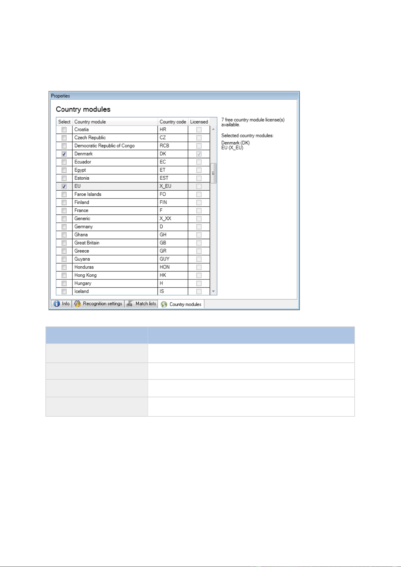
XProtect Professional VMS 2016 R3 - Administrator Manual
Advanced configuration
197
Already licensed modules appear with a check mark in the Licensed column. If the country module
you are looking for is not on your list, contact your vendor.
Name
Description
Select
Click to select or deselect a country module. The list of selected
country modules on the right side updates automatically.
Country Module
Lists the installed country modules.
Country Code
Letters that identify a country module.
Licensed
Shows if a country module is already licensed. You can select a
licensed country module for as many cameras as you like.
When you have changed the settings for your LPR camera, validate your configuration (see
"Validate configuration" on page 198) to see if the system recognizes license plates as well as
expected.
Select snapshots
When you configured the LPR initially with the Add LPR camera wizard, you also added snapshots
(see "About snapshots" on page 189). You can always add additional representative snapshots to
improve the optimization of the configuration.
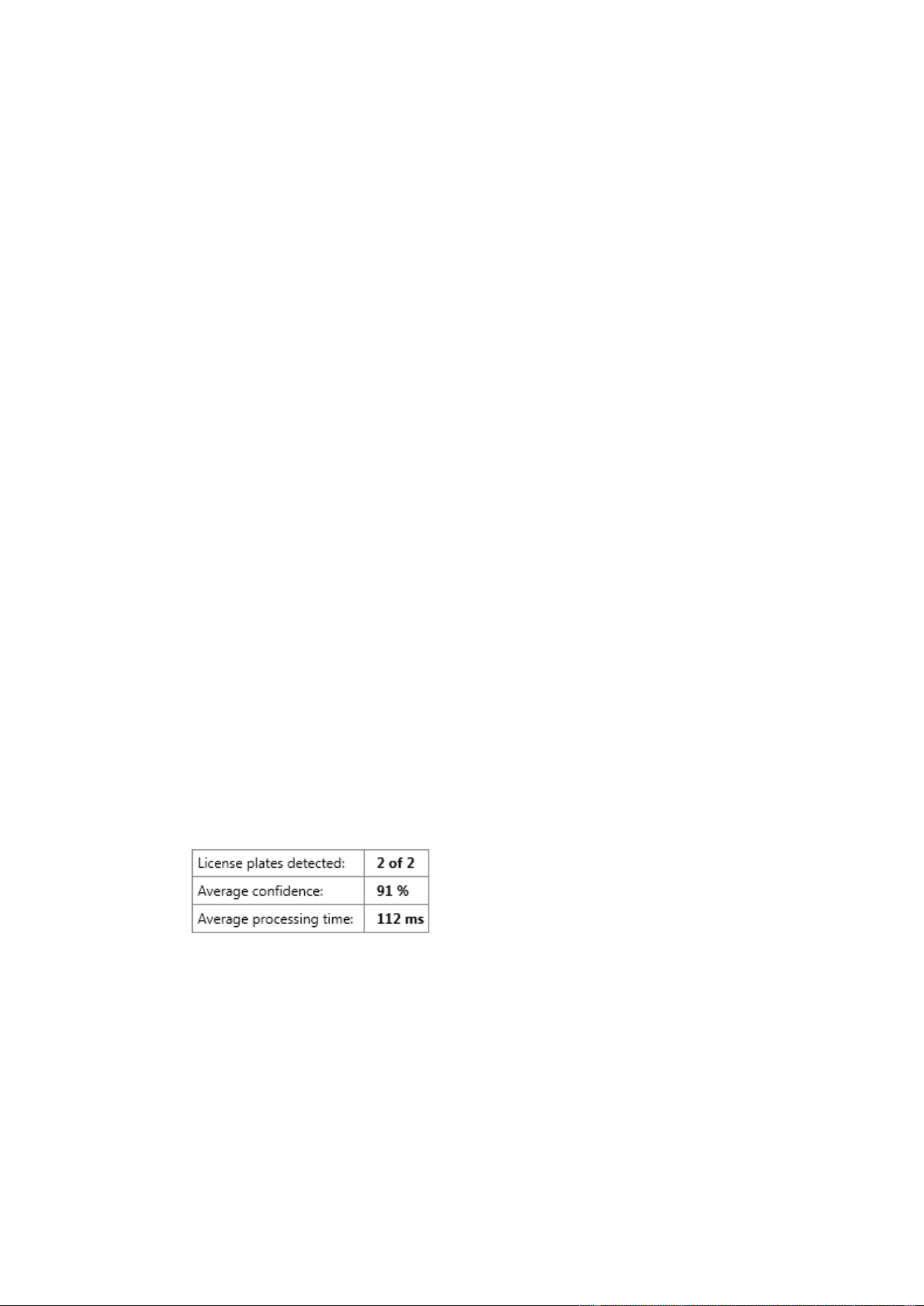
XProtect Professional VMS 2016 R3 - Administrator Manual
Advanced configuration
198
1. Select the relevant camera.
2. In the Recognition settings tab, click Snapshots.
3. Capture snapshots from live video or import them from an external location. Click Next.
The system analyzes the snapshots you have selected for the camera.
4. On the next page, approve or reject each of the snapshots. If the system could not
recognize any license plates, click Previous to add new snapshots in a better quality. If the
system still cannot provide correct recognitions, you probably need to change your
configuration. Check that the camera is mounted and configured correctly (see "About
preparing cameras for LPR" on page 173).
5. When you have approved all snapshots, click Next and close the wizard.
6. On the Recognition settings tab, click Validate configuration (on page 198).
Validate configuration
You can validate your current configuration to see if you need to change any settings or provide
more snapshots. The validation function informs you about how many license plates your system
recognizes, and if they are recognized correctly.
It can help you decide if your confidence level is set correctly and if your system configuration is
optimal.
1. Select the relevant camera.
2. From the Recognition settings tab, click Validate configuration.
Based on the current settings, the system analyzes the snapshots you have selected for the
camera and provides a result summary:
License plates detected: The number of recognized license plates, for example, 3 of
3.
Average confidence: The average percent of confidence with which the license plates
have been recognized.
Average processing time: The average time it took to analyze a snapshot and return
a reading measured in ms.
3. If the current configuration meets your requirements, click Close.
4. If you want to investigate the results further, click Next, and you can review the results for
each snapshot. This helps you to identify the situations that cause problems.
You can validate the configuration as many times as you like and on any LPR camera and with
different settings.
Auto-configure
Auto-configuration of the LPR camera overwrites any manual changes you have made to the
settings. You can select this option if, for example, you have made manual changes that have not
given you good recognition results.

XProtect Professional VMS 2016 R3 - Administrator Manual
Advanced configuration
199
1. From the Recognition settings tab, click Auto-configure.
A new dialog box appears.
2. Confirm that you want to return to auto-configured settings by clicking Next.
The system optimizes the settings.
3. Click Close.
4. If prompted, confirm to save the configuration.
5. Review and validate (see "Validate configuration" on page 198) the new settings.
Working with license plate match lists
About license plate match lists
License plate lists are collections of license plates that you want your LPR solution to treat in a
special way. License plate recognitions are compared with these lists and if there is a match, the
system triggers an LPR event. The events are stored on the event server and can be searched for
and viewed on the LPR tab in XProtect Smart Client.
By default, events are only stored for 24 hours. To change this, open the Options dialog box in the
Management Application and on the Event Server Settings tab, in the Keep events for field,
enter a new time frame.
When you have specified a license plate match list, you can set up additional events and alarms to
be triggered on a match.
Examples:
A company headquarter uses a list of executive management's company car license
plates to grant executives access to a separate parking area. When executives' license
plates are recognized, the LPR solution triggers an output signal that opens the gate to
the parking area.
A chain of gas stations creates a list of license plates from vehicles that have previously
left gas stations without paying for their gas. When such license plates are recognized,
the LPR solution triggers output signals that activate an alarm and temporarily block the
gas supply to certain gas pumps.
Triggered events can also be used for making cameras record in high quality or similar. You can
even use an event to trigger combinations of such actions.
About Unlisted license plates list
Often you would trigger an event when a license plate that is included in a list is recognized, but
you can also trigger an event with a license plate, which is not included in a list.
Example: A private car park uses a list of license plates to grant residents' vehicles access
to the car park. If a vehicle with a license plate that is not on the list approaches the car
park, the LPR solution triggers an output signal which lights a sign telling the driver to
obtain a temporary guest pass from the security office.
To trigger a surveillance system event, when a license plate that is not on a list is recognized, use
the Unlisted license plates list. You select it for a camera like any other list (see "Match lists tab"
on page 196) and set it up like any other list (see "Events triggered by LPR" on page 202).

XProtect Professional VMS 2016 R3 - Administrator Manual
Advanced configuration
200
Add new license plate match lists
1. In the Management Application's navigation pane, select License plate match lists, right-
click and select Add New.
2. In the window that appears, give the list a name and click OK.
As soon as you have created a license plate list, it becomes visible in the License plate
match list and on the Match lists tab for all your LPR cameras.
3. If you want to add columns to the match list, click Custom field and specify the columns in
the dialog box that opens (see "Edit custom fields properties" on page 202).
4. To update the match list, use the Add, Edit, Delete buttons (see "Edit license plate match
lists" on page 200).
5. Instead of defining the match list directly in the Management Application, you can import a
file (see "Import/export license plate match lists" on page 200).
6. If prompted, confirm to save changes.
Edit license plate match lists
1. In the Management Application's navigation pane, select License plate match lists.
2. Go to the Overview pane. Click the relevant list.
3. The License plate match list information window opens.
4. To include new rows to your list, click Add and fill out the fields:
Do not include any spaces.
Always use capital letters.
Examples: ABC123 (correct), ABC 123 (incorrect), abc123 (incorrect)
You can use wildcards in your license plate match lists. Do this by defining plates with a
number of ?'s and the letter(s) and/or number(s) which must appear at specific places.
Examples: ?????A, A?????, ???1??, 22??33, A?B?C? or similar.
5. If prompted, confirm to save changes.
Import/export license plate match lists
You can import a file with a list of license plates that you want to use in a license plate match list.
You have the following import options:
Add license plates to the existing list.
Replace the existing list.
This is useful if, for example, the lists are managed from a central location. Then all local
installations can be updated by distributing a file.
Similarly, you can export the complete list of license plates from a match list to an external
location.
Supported file formats are .txt or .csv.
To import:
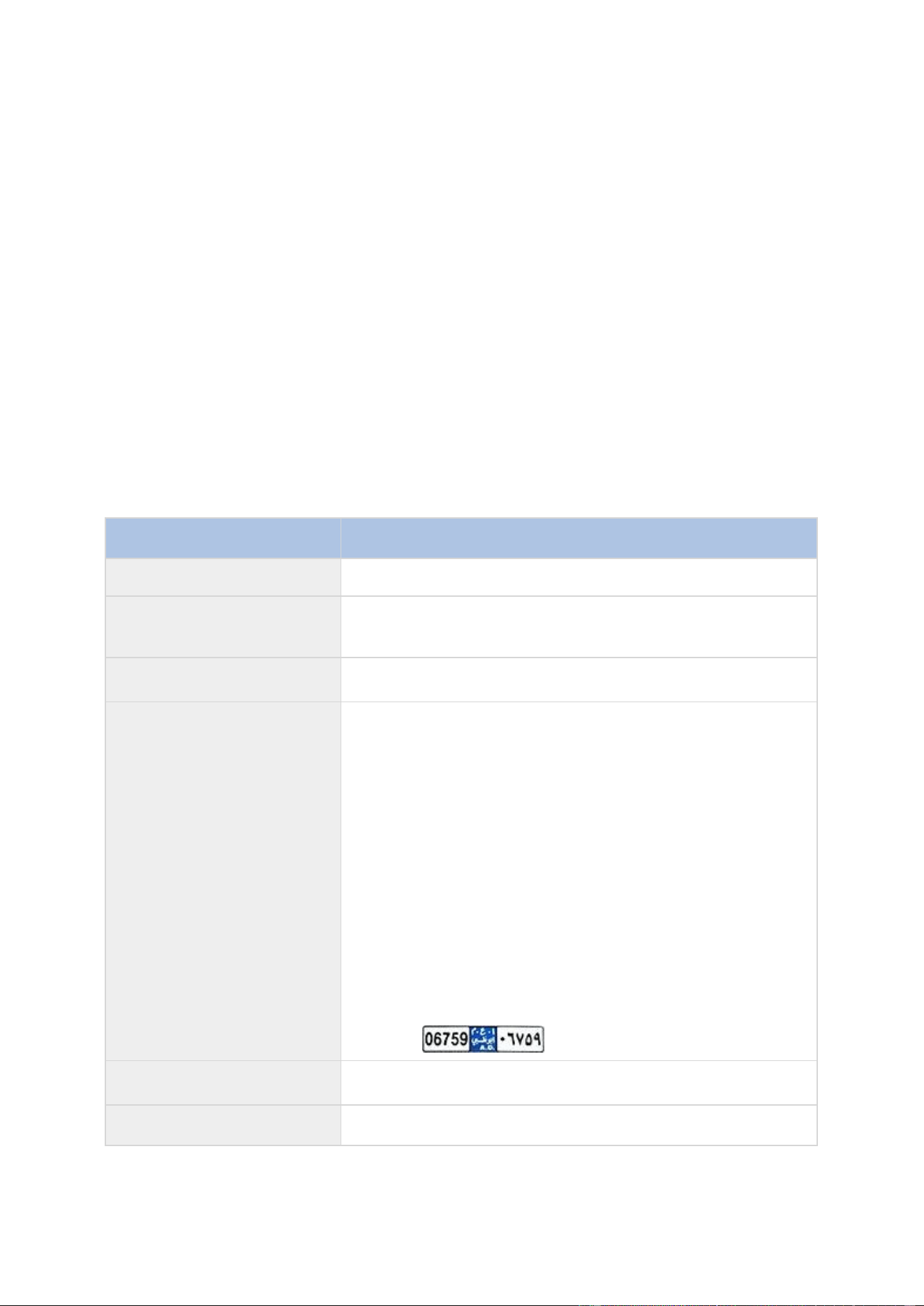
XProtect Professional VMS 2016 R3 - Administrator Manual
Advanced configuration
201
1. In the Management Application's navigation pane, click License plate match lists and
select the relevant list.
2. To import a file, click Import.
3. In the dialog box, specify the location of the import file and the import type. Click Next.
4. Await the confirmation and click Close.
To export:
1. To export a file, click Export.
2. In the dialog box, specify the location of the export file and click Next.
3. Click Close.
4. You can open and edit the exported file in, for example, Microsoft Excel.
License plate match list properties
Name
Description
Name
Shows the name of the list. If needed, you can change the name.
Custom fields
Click to specify which license plate entry columns that you or the
client user can add additional information to. See Custom fields
(properties) (see "Edit custom fields properties" on page 202).
Search
Search the list for specific license plates, numbers, patterns or
similar. If needed, you can use ? as a single wildcard
Add
Click to add a license plate.
Do not include any spaces.
Always use capital letters.
Examples: ABC123 (correct), ABC 123 (incorrect), abc123
(incorrect)
You can use wildcards in your license plate lists. Do this by
defining plates with a number of ?'s and the letter(s) and/or
number(s) which must appear at specific places.
Examples: ?????A, A?????, ???1??, 22??33, A?B?C? and similar.
Some regional areas might have exceptions to these rules. For
example, personalized plates with spaces. Plates with two sets of
characters which must be recognized separately by an underscore
character ( _ ). Or plates from certain regions with letters on a
different background color on parts of the license plate.
Example:
Edit
Click to edit a license plate. You can select multiple rows for
editing.
Delete
Click to delete the selected license plate(s).
XProtect Professional VMS 2016 R3 - Administrator Manual
Advanced configuration
202
Name
Description
Import
Click to import license plates from any comma-separated file, for
example a .txt-file or .csv-file (see "Import/export license plate
match lists" on page 200).
Export
Click to export the entire license plate list to a comma-separated
file, for example a .txt-file or .csv-file (see "Import/export license
plate match lists" on page 200).
Rows per page
Select how many license plates to display in one page (one
screen). You can choose between 50 to 1000 rows.
Events triggered by list
match
Select which event(s) should be triggered by a list match (see
"Events triggered by LPR" on page 202). You can choose between
all available types of events defined in your system.
Edit custom fields properties
You can add columns to your license plate match lists for additional information. You define the
name and number of columns as well as the field content.
The XProtect Smart Client users can update the information in the columns but not the columns
themselves.
Name
Description
Add
Adds a column to the match list. Type a name for the column.
Edit
Click to edit the name of the column.
Delete
Deletes a column.
Up
Changes the order of the columns.
Down
Changes the order of the columns.
Events triggered by LPR
After you have created license plate match lists (see "Add new license plate match lists" on page
200), you can associate them with all types of events defined in your system.
The type of events available depends on the configuration of your system. In connection with LPR,
events are used to trigger output signals for, for example, raising of parking barrier or making
cameras record in high quality. You can also use an event to trigger combinations of such actions.
See About license plate match lists (on page 199) for more examples.
Set up system events triggered by list matches
1. Expand Servers, click License plate match list and select the list to which you want to
associate an event.

XProtect Professional VMS 2016 R3 - Administrator Manual
Advanced configuration
203
2. In the License plate match list information window, next to the Events triggered by
list match selection field, click Select.
3. In the Select triggered events dialog box, select one or more events.
4. If prompted, confirm to save changes.
5. The event is now associated with recognitions on the selected license plate match list.
To trigger a surveillance system event, when a license plate that is not on a list is recognized,
configure the Unlisted license plates list.
Alarms triggered by LPR
You can associate some types of alarms with events from XProtect LPR. Do the following:
1. Create the license plate match list (see "Add new license plate match lists" on page 200)
you want to match license plates against.
2. Add and configure your LPR camera(s) (see "Add LPR camera" on page 190).
3. In the Management Application's navigation pane, expand Alarms, right-click Alarm
Definitions and select to create a new alarm.
4. The Alarm Definition Information window appears. Select the relevant properties (see
"Alarm Definitions for LPR" on page 203).
5. If prompted when done, confirm to save changes.
6. Configure the alarm data settings for LPR (see "Alarm Data Settings for LPR" on page 203).
Alarm Definitions for LPR
Except for defining Triggering events, the settings for Alarm Definitions are the same for LPR
as for the remaining part of the system.
To define triggering events related to LPR, select the event message to use when the alarm is
triggered:
a) In the Triggering events field, in the top drop-down list, decide what type of event to use
for the alarm. The list offers License plate match lists and LPR server events (see
"Working with license plate match lists" on page 199).
b) In the second drop-down list, select the specific event message to use. If you selected
License plate match lists in the drop-down above, select a license plate list. If you
selected LPR server, select the relevant LPR server event message:
LPR camera connection lost
LPR camera running
LPR server not responding
LPR server responding
For information about the remaining alarm definition settings, see the Alarms section.
Alarm Data Settings for LPR
In the Management Application, you must make two specific Alarm List Configuration elements
available for selection in XProtect Smart Client.
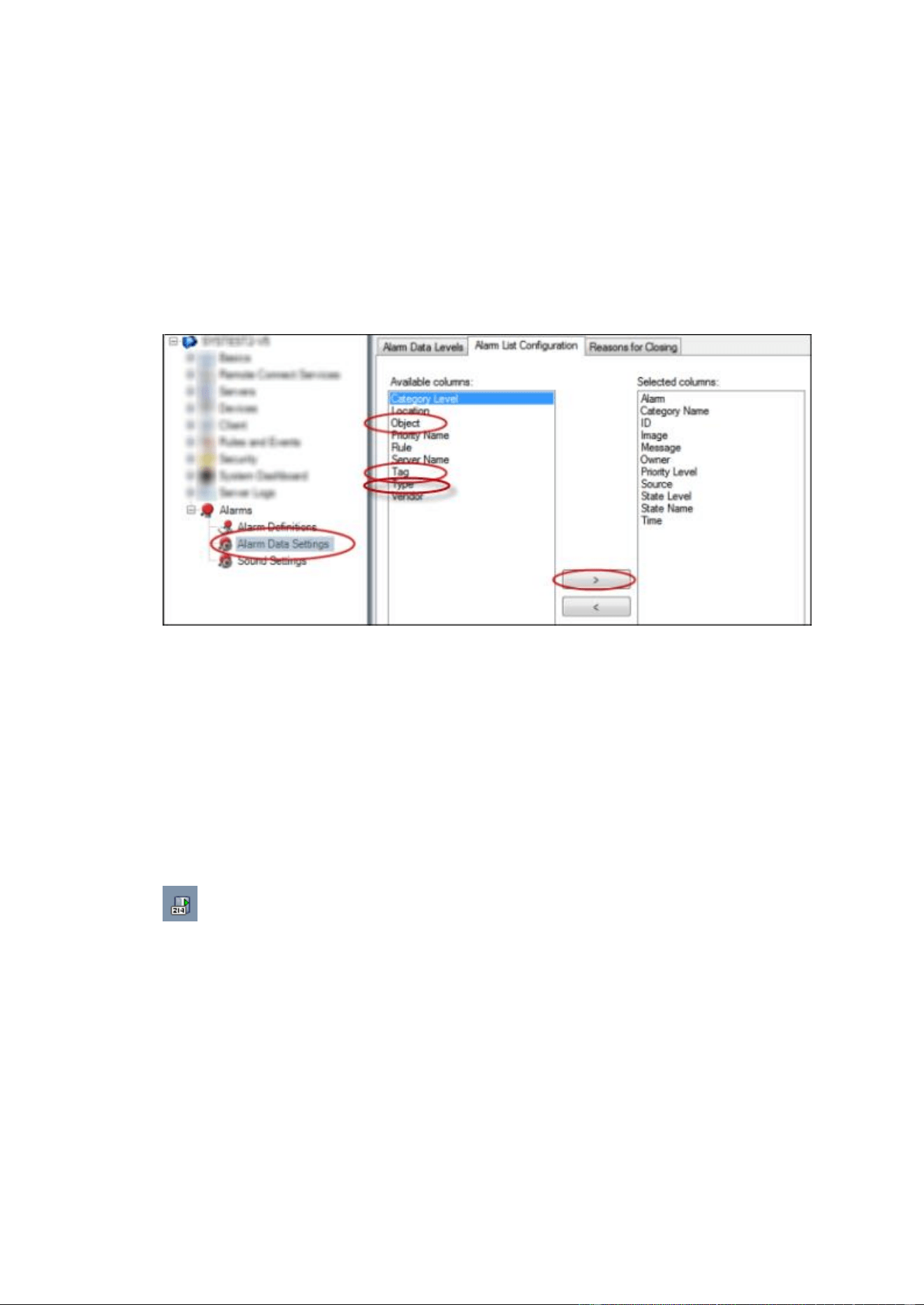
XProtect Professional VMS 2016 R3 - Administrator Manual
Advanced configuration
204
These two elements are used for configuring alarm lists in the Alarm Manager tab in XProtect
Smart Client. The relevant elements are Object, Tag, and Type, which are essential for
recognizing license plate numbers (Object) and country codes (Tag).
Do the following in the Management Application:
1. In the Management Application's navigation pane, expand Alarms, select Alarm Data
Settings.
2. On the Alarm List Configuration tab, select Object, Tag, and Type and click >.
3. If prompted, confirm to save changes.
LPR maintenance
About LPR Server Manager
When you have installed an LPR server, you can check the state of its services with the XProtect
LPR Server Manager. You can, for example, start and stop the LPR Server Service, view status
messages, and read log files.
You access LPR server state information via the LPR Server Manager icon in the
notification area of the computer running the LPR server.
Example: LPR Server Manager
icon in notification area.
In the Management Application, you can get a full overview of the status of all your LPR servers
(see "View LPR server information" on page 187).
Start and stop LPR Server Service
The LPR Server Service starts automatically after installation. If you have stopped the service
manually, you can restart it manually.
1. Right-click the LPR Server Manager icon in the notification area.
2. From the menu that appears, select Start LPR Server Service.

XProtect Professional VMS 2016 R3 - Administrator Manual
Advanced configuration
205
3. If needed, select Stop LPR Server Service to stop the service again.
Show LPR server status
1. On your LPR server, right-click the LPR Server Manager icon in the notification area.
2. From the menu that appears, select Show LPR server status.
If the system is running without problems, the status is: All LPR cameras running.
Other statuses are:
Service not responding
Not connected to surveillance system
Service not running
Event Server not connected
Unknown error
X of Y LPR cameras running
Show LPR server log
Log files are a useful tool for monitoring and troubleshooting the status of the LPR Server Service.
All entries are time-stamped, with the most recent entries at the bottom.
1. In the notification area, right-click the LPR Server Manager icon.
2. From the menu that appears, select Show LPR server Log File.
A log-viewer lists the server activities with time stamps.
Change LPR server settings
The LPR server must be able to communicate with your management server. To enable this, you
specify the IP address or hostname of the management server during the installation of the LPR
server.
If you need to change the address of the management server, do the following:
1. Stop (see "Start and stop LPR Server Service" on page 204) the LPR Server Service.
2. In the notification area, right-click the LPR Server Manager icon.
3. From the menu that appears, select Change settings. The LPR Server Service settings
window appears.
4. Specify the new values and click OK.
5. Restart the LPR Server Service.
Uninstall XProtect LPR
If you want to remove XProtect LPR from your system, uninstall the two components separately
using the regular Windows removal procedure:
On the computers where the LPR plug-in is installed, uninstall Milestone XProtect LPR
[version] Plug-in.

XProtect Professional VMS 2016 R3 - Administrator Manual
Advanced configuration
206
On the computers where the LPR server is installed, uninstall Milestone XProtect LPR
[version] Server.
Milestone Mobile

XProtect Professional VMS 2016 R3 - Administrator Manual
Advanced configuration
207
Milestone Mobile introduction
About Milestone Mobile
Milestone Mobile consists of three components:
Milestone Mobile client
Milestone Mobile server
Milestone Mobile plug-in
The Milestone Mobile client is a mobile surveillance app that you can install and use on your
Android device, Apple device or Windows 8 Phone device. You can use as many installations of
Milestone Mobile client as you need.
For more information, download the Milestone Mobile Client User Guide from the Milestone Systems
website http://www.milestonesys.com/support/manuals-and-guides/.
The Milestone Mobile server and Milestone Mobile plug-in are covered in this manual.
Prerequisites for using Milestone Mobile
Before you can start using Milestone Mobile, you must make sure that you have the following:
A running VMS installed and configured with at least one user.
Cameras and views set up in XProtect® Smart Client.
A mobile device running Android, iOS or Windows 8 with access to Google Play, App Store℠
or Windows Phone Store from which you can download the Milestone Mobile client
application.

XProtect Professional VMS 2016 R3 - Administrator Manual
Advanced configuration
208
Milestone Mobile configuration
About Milestone Mobile server
Milestone Mobile server handles log-ins to the system from Milestone Mobile client from a mobile
device or XProtect Web Client.
A Milestone Mobile server distributes video streams from recording servers to Milestone Mobile
clients. This offers a secure setup where recording servers are never connected to the Internet.
When a Milestone Mobile server receives video streams from recording servers, it also handles the
complex conversion of codecs and formats allowing streaming of video on the mobile device.
You must install Milestone Mobile server on any computer from which you want to access recording
servers. When you install Milestone Mobile server, make sure you log in using an account that has
administrator rights. Otherwise, installation will not complete successfully.
About Milestone Federated Architecture and master/slave servers
If your system supports Milestone Federated Architecture or servers in a master/slave setup, you
can access such servers with your Milestone Mobile client. Use this functionality to gain access to
all cameras on all slave servers by logging in to the master server.
If in a Milestone Federated Architecture setup, you gain access to child sites via the central site.
Install the Milestone Mobile server only on the central site.
This means that when users of the Milestone Mobile client log in to a server to see cameras from all
servers in your system, they must connect to the IP address of the master server. Users must have
administrator rights on all servers in the system in order for the cameras to show up in the
Milestone Mobile client.
Add or edit a Mobile server
1. Go to Servers > Mobile Servers. From the menu that appears, select Create New. Enter
or edit the settings.
Important: If you edit settings for Login method, All cameras view, and Outputs and events
while you or others are connected to the Milestone Mobile client, you must restart the Milestone
Mobile client for the new settings to take effect.
Set up Smart Connect
Enable Universal Plug and Play discoverability on your router
To make it easy to connect mobile devices to Milestone Mobile servers, you can enable Universal
Plug and Play (UPnP) on your router. UPnP enables Milestone Mobile server to configure port
forwarding automatically. However, you can also manually set up port forwarding on your router by
using its web interface. Depending on the router, the process for setting up port mapping can
differ. If you are not sure how to set up port forwarding on your router, see the documentation for
that device.
Note: Every five minutes, the Milestone Mobile server service verifies that the server is available to
users on the Internet. The status displays in the upper left corner of the Properties pane:
.

XProtect Professional VMS 2016 R3 - Administrator Manual
Advanced configuration
209
Requirements
Your Milestone Mobile server must use a public IP address. The address can be static or
dynamic, but typically it's a good idea to use static IP addresses.
You must have a valid license for Smart Connect.
Configure connection settings
1. In Management Application, in the navigation pane, expand Servers, and select Mobile
Server.
2. Select the server and click the Connectivity tab.
3. Use the options in the General group to specify the following:
To make it easy for users to connect mobile devices to Milestone Mobile servers, select
the Enable Smart Connect check box.
Specify the protocol to use in the Connection type field.
Note: If you turn on secure connections, devices running iOS 9.0 or later, or Windows
Phone, can connect only if you have a certificate from a certificate authority (CA)
installed on your Milestone Mobile server. CAs issue digital certificates that verify the
identities of users and websites that exchange data on the Internet. Examples of CAs
are companies like Comodo, Symantec, and GoDaddy.
Before you turn on secure connections, make sure that you are familiar with digital
certificates. To learn how to add a certificate in Milestone Mobile server, see Edit
certificates (see "Edit certificate" on page 222).
Specify the number of seconds before the connection times out.
To let mobile devices find the Milestone Mobile servers that are within range, select the
Enable UPnP discoverability check box.
To enable routers to forward mobile devices to a specific port, select the Enable
automatic port mapping check box.
Send an email message to help users connect
You can make it easy for users to get started with Milestone Mobile by sending them an email
message that includes connection information. You can send the message directly from
Management Application, or you can copy the information to the messaging program you use.
1. In the Email invitation to field, enter the email address for the recipient, and then specify
a language.
2. Next, do one of the following:
To send the message, click Send.
Copy the information to the messaging program you use.
Enable connections on a complex network
If you have a complex network where you have custom settings, you can provide the information
users need to connect.

XProtect Professional VMS 2016 R3 - Administrator Manual
Advanced configuration
210
In the Internet Access group, specify the following:
If you use UPnP port mapping, to direct connections to a specific connection, select the
Configure custom Internet access check box. Then provide the IP address or
hostname, and the port to use for the connection. For example, you might do this if your
router does not support UPnP, or if you have a chain of routers.
If your IP addresses often change, select the Check to retrieve IP address dynamically
check box.
Set up investigations
Set up investigations so that people can use Web Client and Milestone Mobile to access recorded
video and investigate incidents, and prepare and download video evidence.
To set up investigations, follow these steps:
1. In Management Application, click the mobile server, and then click the Investigations tab.
2. Select the Enabled check box. By default, the check box is selected.
3. In the Investigations folder field, specify where to store video for investigations.
4. In the Limit size of investigations to field, enter the maximum number of megabytes
that the investigation folder can contain.
5. Optional: To allow users to access investigations that other users create, select the View
investigations made by others check box. If you do not select this check box, users can
see only their own investigations.
6. Optional: To include the date and time that a video was downloaded, select the Include
timestamps for AVI exports check box.
7. In the Used codec for AVI exports field, select the compression format to use when
preparing AVI packages for download.
Note: The codecs in the list can differ, depending on your operating system. If you do not
see the codec you want to use, you can install it on the computer where Management
Application is running and it will display in this list.
Additionally, codecs can use different compression rates, which can affect video quality.
Higher compression rates reduce storage requirements but can also reduce quality. Lower
compression rates require more storage and network capacity, but can increase quality. It's
a good idea to research the codecs before you select one.
8. In the Failed export data (for MKV and AVI export) field, specify whether to keep the
data that was successfully downloaded, although it can be incomplete, or delete it.
9. To enable users to save investigations, you must grant the following permissions to the
security role assigned to the users:
In XProtect Advanced VMS products, grant the Export permission.
In XProtect Professional VMS products, grant the Database permission.
Clean up investigations
If you have investigations or video exports that you no longer need to keep, you can delete them.
For example, this can be useful if you want to make more disk space available on the server.

XProtect Professional VMS 2016 R3 - Administrator Manual
Advanced configuration
211
To delete an investigation, and all of the video exports that were created for it, select the
investigation in the list, and then click Delete.
To delete individual video files that were exported for an investigation, but keeping the
investigation, select the investigation in the list. In the Investigation details group, click
the Delete icon to the right of the Database, AVI, or MKV fields for exports.
About sending notifications
You can enable Milestone Mobile to notify users when an event occurs, such as when an alarm
triggers or something goes wrong with a device or server. When Milestone Mobile is open on the
mobile device, the app delivers the notification. Users can specify the types of notifications they
want to receive. For example, a user can choose to receive notifications for the following:
All alarms
Only alarms that they own
Only alarms related to the system. These might be when a server goes offline or comes
back online.
You can also use push notifications to notify users who don't have Milestone Mobile open. These are
called push notifications. Push notifications are delivered to the mobile device, and are a great way
to keep users informed while they're on the go.
Using push notifications
Note: To use push notifications, your system must have access to the Internet.
Push notifications use cloud services from Apple, Microsoft, and Google:
Apple Push Notification service (APN)
Microsoft Azure Notification Hub
Google Cloud Messaging Push Notification service
There is a limit to the number of notifications that your system is allowed to send during a period
of time. If your system exceeds the limit, it can send only one notification every 15 minutes during
the next period. The notification contains a summary of the events that occurred during the 15
minutes. After the next period, the limitation is removed.
Requirements for push notifications
The following are requirements for using push notifications:
You must associate one or more alarms with one or more events and rules. This is not
required for system notifications.
Make sure that your Milestone Care™ agreement with Milestone Systems is up-to-date.
Send notifications to mobile devices
You can enable Milestone Mobile to notify users when an event occurs, such as when an alarm
triggers or something goes wrong with a device or server.

XProtect Professional VMS 2016 R3 - Administrator Manual
Advanced configuration
212
Set up system notifications
To send notifications related to the system, such as when a server goes offline, follow these steps:
1. In Management Application, select the mobile server, and then click the Notifications tab.
2. Select the Notifications check box.
Set up push notifications on the Milestone Mobile server
To set up push notifications, follow these steps:
1. In Management Application, select the mobile server, and then click the Notifications tab.
2. To send notifications to all mobile devices that connect to the server, select the
Notifications check box.
3. To store information about the users and mobile devices that connect to the server, select
the Maintain device registration check box.
Note: The server sends notifications only to the mobile devices in this list. If you clear the
Maintain device registration check box and save the change, the system clears the list.
To receive push notifications again, users must reconnect their device.
Stop sending push notifications to specific mobile devices, or all mobile
devices
There are several ways to stop sending push notifications to mobile devices.
1. In Management Application, select the mobile server, and then click the Notifications tab.
2. Do one of the following:
For individual devices, clear the Enabled check box for each mobile device. The user
can use another device to connect to the Milestone Mobile server.
For all devices, clear the Notifications check box.
To temporarily stop for all devices, clear the Maintain device registration check box and then
save your change. The system sends notifications again after users reconnect.
About using Video Push to stream video
You can set up Video Push so that users can keep others informed about a situation, or record
video to investigate it later, by streaming video from their mobile device's camera to your XProtect
surveillance system.
Set up Video Push to stream video
To let users stream video from their mobile devices to an XProtect surveillance system, set up
Video Push on a Milestone Mobile server.
In Management Application, perform these steps in the following order:
1. Set up a channel that the mobile device can use to stream video to the recording server.
2. Add the Video Push Driver as a hardware device on the recording server. The driver
simulates a camera device so that you can stream video to the recording server.

XProtect Professional VMS 2016 R3 - Administrator Manual
Advanced configuration
213
3. Assign the Video Push Driver device to the channel.
This topic describes each of these steps.
Set up a channel for streaming video
Note: Each channel requires a hardware device license.
To add a channel, follow these steps:
1. In the navigation pane, select Mobile Server, and select the mobile server.
2. On the Video Push tab, select the Video Push check box.
3. In the bottom right corner, click Add to add a video push channel under Channels
mapping.
4. Enter the user name of the user account that will use the channel. This user account must
be allowed to access the Milestone Mobile server and recording server.
Note: To use Video Push, users must log in to Milestone Mobile on their mobile device using
the user name and password for this account.
5. Make a note of the port number. You will need it when you add the Video Push driver as a
hardware device on the recording server.
6. Click OK to close the Video Push Channel dialog box and the save the channel.
Add the Video Push Driver as a hardware device on the recording server
1. In the navigation pane, click Recording Servers.
2. Right-click the server that you want to stream video to, and click Add Hardware to open
the Add Hardware wizard.
3. Select Manual as the hardware detection method, and click Next.
4. Enter credentials for the camera, as follows:
To use the factory default credentials from the camera factory, click Next. Typically,
factory settings are used.
If you have changed the credentials on the device, enter that information, and then
click Next.
Note: These are the credentials for the hardware, not for the user. They are not related to
the user name for the channel.
5. In the list of drivers, expand Other, select the Video Push Driver check box, and then
click Next.
Note: The system generates a MAC address for the Video Push Driver device. We
recommend that you use this address. Change it only if you experience problems with the
Video Push Driver device. For example, if you need to add a new address and port number.
6. In the Address field, enter the IP address of the computer where Milestone Mobile server is
installed.
7. In the Port field, enter the port number for the channel you created for streaming video.
The port number was assigned when you created the channel.

XProtect Professional VMS 2016 R3 - Administrator Manual
Advanced configuration
214
8. In the Hardware model column, select Video Push Driver, and then click Next.
9. When the system detects the new hardware, click Next.
10. In the Hardware name template field, specify whether to display either the model of the
hardware and the IP address, or the model only.
11. Specify whether to enable related devices by selecting the Enabled check box. You can add
related devices to the list for Video Push Driver, even though they are not enabled. You
can enable them later.
Note: If you want to use location information when you stream video, you must enable the
Metadata port.
12. Select the default groups for the related devices on the left, or select a specific group in the
Add to Group field. Adding devices to a group can make it easier to apply settings to all
devices at the same time or replace devices.
Add the Video Push Driver device to the channel for video push
1. In the Site navigation pane, click Mobile Servers, and then click the Video Push tab.
2. Click Find Cameras. If successful, the name of the Video Push Driver camera displays in
the Camera Name field.
3. Save your configuration.
Remove a channel that you don't need
You can remove channels that you no longer use.
Select the channel to remove, and then click Remove in the lower right corner.
About actions
You can manage the availability of the Actions tab in the Milestone Mobile client by enabling or
disabling this on the Mobile server tab. Actions are by default enabled, and all available actions for
the connected devices are shown here.
About naming an output for use in Milestone Mobile
In order to get actions shown correctly together with current camera, it is important that the
output uses the exact same name as the camera.
Example:
If you have a camera named "AXIS P3301,P3304 - 10.100.50.110 - Camera 1", you must also
name the action "AXIS P3301,P3304 - 10.100.50.110 - Camera 1".
You can add a further description to the title afterwards, for example "AXIS P3301,P3304 -
10.100.50.110 - Camera 1 - Light switch".
Important: If you do not follow these naming conventions, actions are not available in the action
list for the associated camera's view. Instead, actions appear in the list of other actions on the
Actions tab.

XProtect Professional VMS 2016 R3 - Administrator Manual
Advanced configuration
215
Add an automatic export rule
1. In the Management Application, click the relevant Mobile server > Export Tab.
2. Under Automatic Exports, click Add to open the Auto Export Rule window.
3. Set the relevant Auto Export Rule window settings.
4. When finished, click OK.
Mobile server settings
General
The following table describes the settings on this tab.
Name
Description
Server name
Enter a name of the Milestone Mobile server.
Description
Enter an optional description of the Milestone Mobile server.
Mobile server
Choose between all Milestone Mobile servers currently installed to
the specific system. Only Milestone Mobile servers that are
running are shown in the list.
Login method
Select the authentication method to use when users log in to the
server. You can choose between the following options:
Automatic, Windows authentication, or Basic
authentication.
Enable XProtect Web Client
Enable access to XProtect Web Client.
Enable all cameras view
Include the All Cameras view. This view displays all of the
cameras that a user is allowed to view on a recording server.
Enable actions (outputs and
events)
Enable access to actions in Milestone Mobile clients.
Enable keyframes
Stream only keyframes when streaming video. This uses less
bandwidth.
Enable full-size images
Enable the Milestone Mobile server to send full-size images to the
Milestone Mobile client or XProtect Web Client.
Note that enabling full-size images uses more bandwidth.
Additionally, enabling this option disables all rules set up in the
Performance settings.
Enable direct streaming
Choose how to handle direct streaming in XProtect Web Client.
Choose between enforcing the use of direct streaming, enforcing
it when possible, or never enforcing it.
Enabled
Enable/disable logging of Milestone Mobile client's actions in a
separate log file.
Log file location
Path to where log files are saved.
Keep logs for
Number of days to keep logs for (default three days).

XProtect Professional VMS 2016 R3 - Administrator Manual
Advanced configuration
216
Name
Description
Configuration backup
Import or export your Milestone Mobile server configuration. Your
system stores the configuration in an XML file.
Connectivity
In the General section, specify the following settings.
Name
Description
Connection type
Choose how clients should connect to the Milestone Mobile
server. You can choose between the following options: HTTP
only, HTTP and HTTPS or HTTPS Only.
Note: If you select HTTPS Only, devices running iOS 9.0 or
later, or Windows Phone, can connect only if you have a
certificate from a certificate authority (CA) installed on your
Milestone Mobile server. CAs issue digital certificates that verify
the identities of users and websites that exchange data on the
Internet. Examples of CAs are companies like Comodo,
Symantec, and GoDaddy. Before you turn on secure connections,
make sure that you are familiar with digital certificates. To learn
how to add a certificate in Milestone Mobile server, see Edit
certificate (on page 222).
Client timeout (HTTP)
Set a time frame for how often the Milestone Mobile client must
indicate to the Mobile server that it is up and running. The default
value is 30 seconds.
Milestone recommends that you do not increase the time frame.
Settings in the Internet Access section are used in the following tasks:
Configure connection settings.
Send an email message to help users connect their mobile device to Milestone Mobile
servers.
Enable connections to Milestone Mobile servers on a complex network.
For step-by-step descriptions of these tasks, see Set up Smart Connect (on page 208).
Server Status
See the status details for your Mobile server. The details are read-only:
Name
Description
Server active since
Shows how long the Mobile server has been running since it was
last stopped.
CPU usage
Shows current CPU usage on the Mobile server.
Internal bandwidth
Shows the current bandwidth in use between the Mobile server
and the relevant recording server.
External bandwidth
Shows the current bandwidth in use between the mobile device
and Mobile server.

XProtect Professional VMS 2016 R3 - Administrator Manual
Advanced configuration
217
Name
Description
User Name column
Shows user name(s) of the Mobile server user(s) connected to
the Mobile server.
State column
Shows the current relation between the Mobile server and the
Milestone Mobile client user in question. Is the user connected (a
state preliminary to servers exchanging keys and encrypting
credentials) or is he/she actually logged in? Possible states are:
Connected and Logged In XProtect.
Bandwidth Usage column
Shows the level of bandwidth used by the Mobile server client
user in question.
Live Streams column
Shows the number of live video streams currently open for the
Milestone Mobile client user in question.
Playback Streams column
Shows the number of playback video streams currently open for
the relevant mobile client user.
Video Push streams
Shows the number of Video Push stream currently open for the
relevant mobile client user.
Direct Streams
Shows the number of live video streams using Direct Streaming
that are currently open for the relevant mobile user.
Video Push
You can specify the following settings if you enable Video push:
Name
Description
Video push
Enable Video push on the Mobile server.
Number of channels
Specify the number of enabled Video push channels in your
XProtect system.
Channel column
Shows the channel number for the relevant channel. Non-
editable.
Port
Port number for the relevant Video push channel.
MAC
MAC address for the relevant Video push channel.
User Name
Enter the user name associated with the relevant video push
channel.
Camera Name
Shows the name of the camera if the camera has been identified.
Once you have completed all necessary steps (see "Set up Video Push to stream video" on page
212), click Find Cameras to search for the relevant camera.
Investigations
You can enable investigations so that people can use XProtect Web Client and Milestone Mobile to
access recorded video and investigate incidents, and prepare and download video evidence.
The following table describes the settings for investigations.

XProtect Professional VMS 2016 R3 - Administrator Manual
Advanced configuration
218
Name
Description
Investigations folder
Specify where to store video for investigations.
Limit size of investigations
to
Enter the maximum number of megabytes that the investigations
folder can contain.
View investigations made by
others
Select this check box to allow users to access investigations that
they did not create.
Include timestamps for AVI
exports
Select this check box to include the date and time that the AVI
file was downloaded.
Used codec for AVI exports
Select the compression format to use when preparing AVI
packages for download.
The codecs you can choose from can differ, depending on your
operating system. If you do not see the codec you want, you can
add it to the list by installing it on the computer where the
Milestone Mobile server is running.
Failed export data (for MKV
and AVI export)
Select whether to keep the data that was not successfully
prepared for download in an investigation, or delete it.
Notifications
Use the Notifications tab to turn on or turn off system notifications and push notifications.
If you turn on notifications, and have configured one or more alarms and events, Milestone Mobile
notifies users when an event occurs. When the app is open, notifications are delivered in Milestone
Mobile on the mobile device. Push notifications notify users who don't have the Milestone Mobile
open. These notifications are delivered to the mobile device.
For more information, see Send notifications to mobile devices (on page 211).
The following table describes the settings on this tab.
Name
Description
Notifications
Select this check box to turn on notifications.
Maintain device registration
Select this check box to store information about the devices and
users who connect to this server. The system sends notifications
to these devices.
If you clear this check box, you also clear the list of devices. For
users to start receiving notifications again, you must select the
check box, and the users must connect their devices to the
server again.
Enabled
Select this check box to send notifications to the device.
Registered devices
A list of the mobile devices that have connected to this server.
You can start or stop sending to specific devices by selecting or
clearing the Enabled check box.
Performance
On the Performance tab, you can set the following limitations on the Milestone Mobile server's
performance:
XProtect Professional VMS 2016 R3 - Administrator Manual
Advanced configuration
219
Level 1
Level 1 is the default limitation placed on the Milestone Mobile server. Any limitations you set here
are always applied to the Milestone Mobile's video stream.
Name
Description
Level 1
Select the check box to enable the first level of limitations to
Milestone Mobile server performance.
Max FPS
Set a limit for the maximum number of frames per second (FPS)
to send from the Milestone Mobile server to clients.
Max image resolution
Set a limit for the image resolution to send from the Milestone
Mobile server to clients.
Level 2
If you would rather like to enforce a different level of limitations that the default one in Level 1,
you can select the Level 2 check box instead. You cannot set any settings higher than what you
have set them to in the first level. If you, for example, set the Max FPS to 45 on Level 1, you can
set the Max FPS on Level 2 only to 44 or below.
Name
Description
Level 2
Select the check box to enable the second level of limitations to
Milestone Mobile server performance.
CPU threshold
Set a threshold for the CPU load on the Milestone Mobile server
before the system enforces video stream limitations.
Bandwidth threshold
Set a threshold for bandwidth load on the Milestone Mobile server
before the system enforces video stream limitations.
Max FPS
Set a limit for the maximum number of frames per second (FPS)
to send from the Milestone Mobile server to clients.
Max image resolution
Set a limit for the image resolution to send from the Milestone
Mobile server to clients.
Level 3
You can also select a Level 3 check box to create a third level for limitations. You cannot set any
settings higher than what you have set them to in Level 1 and Level 2. If you, for example, set
the Max FPS to 45 on Level 1 and to level 32 on Level 2, you can set the Max FPS on Level 3
only to 31 or below.
Name
Description
Level 3
Select the check box to enable the second level of limitations to
Milestone Mobile server performance.
CPU threshold
Set a threshold for the CPU load on the Milestone Mobile server
before the system enforces video stream limitations.
Bandwidth threshold
Set a threshold for bandwidth load on the Milestone Mobile server
before the system enforces video stream limitations.

XProtect Professional VMS 2016 R3 - Administrator Manual
Advanced configuration
220
Max FPS
Set a limit for the frames per second (FPS) to send from the
Milestone Mobile server to clients.
Max image resolution
Set a limit for the image resolution to send from the Milestone
Mobile server to clients.
The system does not instantly switch from one level to another level. If your CPU or bandwidth
threshold goes less than five percent above or below the indicated levels, the current level stays in
use.
Note that if you enable Enable full-size images on the General tab, none of the Performance
levels are applied.
Log Settings
Fill in and specify the following log settings:
Name
Description
Enabled
Enable/disable logging of Milestone Mobile client's actions in a
separate log file.
Log file location
Path to where log files are saved.
Keep logs for
Number of days to keep logs for (default three days).
CPU usage
Default level of CPU usage which will trigger a warning in the log.
Internal bandwidth
Default internal bandwidth usage which will trigger a warning in the
log.
External bandwidth
Default external bandwidth usage which will trigger a warning in the
log.
Check every
Default time frame (30 sec.) for checking warning levels.

XProtect Professional VMS 2016 R3 - Administrator Manual
Advanced configuration
221
Mobile Server Manager
About Mobile Server Manager
The Mobile Server Manager is a tray-controlled feature connected to the Mobile server. Right-
clicking the Mobile Server Manager icon in the system tray opens a menu from which you can
easily access Mobile server functionality.
You can:
Open XProtect Web Client (see "Access XProtect Web Client" on page 21)
Start, stop and restart the Mobile service (see "Start, stop and restart Mobile service" on
page 224)
Fill in or change surveillance server credentials (see "Fill in/edit surveillance server
credentials" on page 223)
Show/edit port numbers (on page 223)
Edit certificate (on page 222)
Open today's log file (see "About accessing logs and exports" on page 222)
Open log folder (see "About accessing logs and exports" on page 222)
Open export folder (see "About accessing logs and exports" on page 222)
Show Mobile server status (see "About show status" on page 222)
Access XProtect Web Client
If you have a Milestone Mobile server installed on your computer, you can use the XProtect
Web
Client to access your cameras and views. Because you do not need to install XProtect Web Client,
you can access it from the computer where you installed the Milestone Mobile server, or any other
computer you want to use for this purpose.
1. Set up the Milestone Mobile server in the Management Application.
2. If you are using the computer where Milestone Mobile server is installed, you can right-click
the Milestone Mobile Server icon in the system tray, and select Open XProtect Web
Client.
3. If you are not using the computer where Milestone Mobile server is installed, you can access
it from a browser. Continue with step 4 in this process.
4. Open an Internet browser (Internet Explorer, Mozilla Firefox, Google Chrome or Safari).
5. Type the external IP address, that is, the external address and port of the server on which
the Milestone Mobile server is running.
Example: The Milestone Mobile server is installed on a server with the IP address 127.2.3.4
and is configured to accept HTTP connections on port 8081 and HTTPS connections on port
8082 (default settings of the installer).
In the address bar of your browser, type: http://1.2.3.4:8081 or https://1.2.3.4:8082,
depending on whether you want to use a standard HTTP connection or a secure HTTPS
connection. You can now begin using XProtect Web Client.

XProtect Professional VMS 2016 R3 - Administrator Manual
Advanced configuration
222
6. Add the address as a bookmark in your browser for easy future access to XProtect Web
Client. If you use XProtect Web Client on the local computer on which you installed the
Milestone Mobile server, you can also use the desktop shortcut which the installer creates.
Click the shortcut to launch your default browser and open XProtect Web Client.
You must clear the cache of Internet browsers running the XProtect Web Client before you can use
a new version of the XProtect Web Client. System administrators must ask their XProtect Web
Client users to clear their browser cache after upgrading, or force this action remotely (you can do
this action only in Internet Explorer in a domain).
About show status
Right-click the Mobile Server Manager icon and select Show Status or double-click the Mobile
Server Manager icon to open a window that shows the status of the Mobile server. You can see the
following information:
Name
Description
Server running since
Time and date of the time when the Mobile server was last
started.
Connected users
Number of users currently connected to the Mobile server.
Hardware decoding
Indicates if hardware accelerated decoding is in action on the
Mobile server.
CPU usage
How many % of the CPU is currently being used by the Mobile
server.
CPU usage history
A graph detailing the history of CPU usage by the Mobile server.
About accessing logs and exports
The Mobile Server Manager lets you quickly access the log file of the day, open the folder to which
logs files are saved, and open the folder to which exports are saved.
To open any one of these, right-click the Mobile Server Manager and select Open Today's Log
File, Open Log Folder or Open Export Folder respectively.
Important: If you uninstall Milestone Mobile from your system, its log files are not deleted.
Administrators with proper rights can access these log files at a later timer, or decide to delete
them if they are not needed any longer. The default location of the log files is in the ProgramData
folder. If you change the default location of log files, existing logs are not copied to the new
location nor are they deleted.
Edit certificate
If you want to use a secure HTTPS protocol to establish connection between a Milestone Mobile
server and your mobile device or the XProtect Web Client, you must have a valid certificate for the
device or web browser to accept the connection. The certificate confirms that the certificate holder
is authorized to establish the connection.
When you install Milestone Mobile server, you generate a self-signed certificate if you run a
Typical installation. If you run a Custom installation, you can choose between generating a self-
signed certificate or loading a file that contains a certificate issued by another trusted site.
Note: If you want to use secure connections (HTTPS) devices running iOS 9.0 or later, or Windows
Phone, can connect only if you have a certificate from a certificate authority (CA) installed on your
Milestone Mobile server. CAs issue digital certificates that verify the identities of users and websites

XProtect Professional VMS 2016 R3 - Administrator Manual
Advanced configuration
223
that exchange data on the Internet. Examples of CAs are companies like Comodo, Symantec, and
GoDaddy. Before you turn on secure connections, make sure that you are familiar with digital
certificates.
If you want use a different certificate, you can do the following.
1. On a computer where Management Application are installed, right-click the Milestone
Mobile Server icon and select Edit Certificate...
2. Choose one of the following:
Generate a self-signed certificate
Load a certificate file
Generate a self-signed certificate
1. Choose the Generate a self-signed certificate option and click OK.
2. Wait for a few seconds while the system installs the certificate.
3. When finished, a window opens and informs you that the certificate was installed
successfully. The Mobile service restarts to apply the change.
Locate a certificate file
1. Choose the Load a certificate file option.
2. Fill in the path for the certificate file or click the ... box to open a window where you can
browse for the file.
3. Fill in the password connected to the certificate file.
4. When finished, click OK.
Fill in/edit surveillance server credentials
1. Right-click the Mobile Server Manager and select Surveillance Server Credentials.
2. Fill in the Server URL.
3. Select what user you want to log in as:
Local system administrator (no credentials needed) or
A specified user account (credentials needed).
4. If you have chosen a specified user account, fill in User Name and Password.
5. When finished, click OK.
Show/edit port numbers
1. Right-click the Mobile Server Manager and select Show/Edit Port Numbers.
2. To edit the port numbers, type the relevant port number. You can indicate a standard port
number (for HTTP connections) and/or a secured port number (for HTTPS connections).

XProtect Professional VMS 2016 R3 - Administrator Manual
Advanced configuration
224
3. When you are done, click OK.
Start, stop and restart Mobile service
If needed, you can start, stop and restart the Mobile service from the Mobile Server Manager.
To perform any of these tasks, right-click the Mobile Server Manager and select Start
Mobile service, Stop Mobile service or Restart Mobile service respectively.
Frequently asked questions (FAQs)
1. Why can't I connect from my Milestone Mobile client to my recordings/Milestone
Mobile server?
In order to connect to your recordings, the Milestone Mobile server must be installed on the
server that runs your XProtect system or alternatively on a dedicated server. The relevant
Milestone Mobile settings are also needed in your XProtect video management setup. These
are installed as either plug-ins or as part of a product installation or upgrade. For details on
how to get the Milestone Mobile server and how to integrate the Milestone Mobile client-
related settings in your XProtect system, see the configuration section (see "Milestone
Mobile configuration" on page 208).
2. I installed the Milestone Mobile server to XProtect Corporate, but I can’t connect
to the server from my device. What is the problem?
After you have installed the Milestone Mobile server to your XProtect Corporate (4.0+), you
must install the Milestone Mobile plug-in to see the Milestone Mobile server in your XProtect
Corporate setup. When you have installed the Milestone Mobile plug-in, locate the plug-in
under Servers > Mobile Servers and right-click to add a new mobile server. Here, you
add the details about your Milestone Mobile server (Server name, Description (optional),
Server Address, Port and more). Once you finish, restart the Milestone Mobile Service (from
Windows Services) and try to reconnect with your device.
3. How do I add a Milestone Mobile server/location/site to my Milestone Mobile
client?
You do this from the Milestone Mobile client. When you open it for the first time, you must
add one or more mobile servers in order to retrieve video from your cameras. Your added
Milestone Mobile servers will be listed alphabetically. You can add as many Milestone Mobile
servers as needed, as long as you have the needed log-in credentials.
4. Why is the image quality sometimes poor when I view video in the Milestone
Mobile client?
The Milestone Mobile server automatically adjusts image quality according to the available
bandwidth between the server and client. If you experience lower image quality than in the
XProtect® Smart Client, you might have too little bandwidth to get full resolution images
through the Milestone Mobile client. The reason for this can either be too little upstream
bandwidth from the server or too little downstream bandwidth on the client. See the
XProtect Smart Client User Manual which you can download from our website
http://www.milestonesys.com/support/manuals-and-guides/.
If you are in an area with mixed wireless bandwidth, you may notice that the image quality
improves when you enter an area with better bandwidth.
5. How do I create views?

XProtect Professional VMS 2016 R3 - Administrator Manual
Advanced configuration
225
You cannot create or configure views in the Milestone Mobile client. It uses views and
related names already created in the XProtect Smart Client. If you do not have any views
set up, you can use the All cameras view to see all the cameras in your system. You can
always add more views to the XProtect Smart Client at a later time.
6. How do I add a new Milestone Mobile user?
A Milestone Mobile user is just like any other XProtect user. You add a new Milestone Mobile
user the same way you normally add a new user in your Management Application: right-
click on Users in the Navigation Pane and select Add new basic user or Add new
Windows user. If you select new basic user, you must change the server login method to
Automatic or Basic Only depending on your system. You change your server login
method from the Login method drop-down menu on the General tab of the Mobile Server
entry under Servers > Mobile Servers in the Management Application.
7. Can I control my pant-tilt-zoom (PTZ) cameras and use presets from Milestone
Mobile client?
Yes, in the Milestone Mobile client, you can control your connected PTZ cameras and use
presets in live mode.
8. How can I navigate my recordings?
Android: You can navigate through your recordings in playback mode. Select the camera
you wish to view in playback mode and choose Menu > Playback. Once you are in
playback mode you can search through your recordings using the control buttons. You also
have the option to go to a specific time by choosing Menu > Go to time. Once you have
chosen Go To time, select the date and time you want to view.
iOS: You can navigate through your recordings in playback mode. Select the camera you
wish to view in playback mode and tap Playback. Once you are in playback mode, you can
search through your recordings using the control buttons. You also have the option to go to
a specific time by choosing Menu > Go to time. Once you have chosen Go to time, select
the date and time you want to view and click Confirm.
9. Can I view live and recorded video at the same time?
Yes, in playback mode, you get a small picture-in-picture (PiP) view live from the same
camera.
10. Can I use the Milestone Mobile client without a 3G data plan?
Yes, you can use Milestone Mobile through Wi-Fi. Either locally on the same network as
your XProtect system or at a different location, such as a public network in a café or a
home network. Note that bandwidth on public networks vary and may affect the image
quality of the video streams.
11. Can I use the Milestone Mobile client with a 4G/LTE data plan?
Yes, you can use any data connection on your mobile device that allows you to access the
internet to connect to your XProtect video management system.
12. Can I add multiple servers to the Milestone Mobile client?
When you open the Milestone Mobile client for the first time, you must add one or more
mobile servers in order to retrieve video from your cameras. These mobile servers are
listed alphabetically. If you want to retrieve video from additional servers, repeat this
process. You can add as many mobile servers as needed, as long as you have the relevant
log-in credentials.

XProtect Professional VMS 2016 R3 - Administrator Manual
Advanced configuration
226
13. Why is the image quality poor when I connect to my XProtect video management
system at home through Wi-Fi at my office?
Check your home internet bandwidth. Many private internet connections have different
download and upload bandwidths often described as, for example, 20 Mbit/2 Mbit. This is
because home users rarely need to upload large amounts of data to the internet, but
consume a lot of data instead. The XProtect video management system needs to send video
to the Milestone Mobile client and is limited by your connection’s upload speed. If low image
quality is consistent on multiple locations where the download speed of the Milestone Mobile
client’s network is good, the problem might be solved by upgrading the upload speed of
your home internet connection.
14. Where are my screenshots saved?
Android: Snapshots are saved to your device's SD card at: /mnt/sdcard/XProtect.
iOS: Snapshots are saved to your device and can be accessed from Photos on your device.
You cannot change the default settings on neither Android nor iOS.
15. How do I avoid the security warning when I run XProtect Web Client through an
HTTPS connection?
The warning appears because the server address information in the certificate is incorrect.
The connection will still be encrypted.
The self-signed certificate in the Milestone Mobile server needs to be replaced with your
own certificate matching the server address used to connect to the Milestone Mobile server.
These certificates are obtained through official certificate signing authorities such as
Verisign. Consult the chosen signing authority for more details.
Milestone Mobile server does not use Microsoft IIS. This means that instructions provided
for generating certificate signing request (CSR) files by the signing authority using the IIS is
not applicable for the Milestone Mobile server. You must manually create CSR-file using
command line certificate tools or other similar third-party application. Note that this process
should be performed by system administrators and advanced users only.
16. Does my processor support hardware-accelerated decoding?
Only newer processors from Intel support hardware accelerated decoding. Check Intel
website
http://ark.intel.com/search/advanced?s=t&MarketSegment=DT&QuickSyncVideo=true if
your processor is supported.
In the menu, make sure Technologies > Intel Quick Sync Video is set to Yes.
If your processor is supported, hardware-accelerated decoding is enabled by default. You
can see the current status in Show status in the Mobile Server Manager (see "About show
status" on page 222).
17. Does my operating system support hardware-accelerated decoding?
Only Windows 8 and Windows Server 2012 or newer are supported.
Make sure you install the newest graphic drivers from the Intel website on your system.
These drivers are not available from Windows Update.
Hardware-accelerated decoding is not supported, if the mobile server is installed in a virtual
environment.
18. How do I disable hardware-accelerated decoding on the mobile server?
(Advanced)

XProtect Professional VMS 2016 R3 - Administrator Manual
Advanced configuration
227
If the processor on the mobile server supports hardware accelerated decoding, it is by
default enabled. To turn hardware-accelerated decoding off, do the following:
1. Locate the file VideoOS.MobileServer.Service.exe.config. The path is typically:
C:\Program Files\Milestone\Milestone Mobile
Server\VideoOS.MobileServer.Service.exe.config.
2. Open the file in Notepad or a similar text editor. If necessary, associate the file type
.config with Notepad.
3. Locate the field <add key="HardwareDecodingMode" value="Auto" />.
4. Replace the value "Auto" with "Off".
5. Save and close the file.
19. I just turned on my firewall, and now I can't connect a mobile device to my
server. Why not?
If your firewall was turned off while you installed Milestone Mobile server, you must
manually enable TCP and UDP communications.
Milestone ONVIF Bridge
About Milestone ONVIF Bridge
Available functionality depends on the system you are using. See the Product comparison chart (on
page 11) for more information.
ONVIF is an open, global forum that is working to standardize and secure the way that IP video
surveillance products communicate. The goal is to make it easy to exchange video and audio data.
For example, to enable law enforcement, surveillance centers, or similar organizations to quickly
access live and recorded video streams in any IP-based surveillance system.
Milestone Systems wants to support this goal, and has developed the Milestone ONVIF Bridge
toward that end. Milestone ONVIF Bridge is a part of the Milestone Open Platform, and offers an
interface that supports the parts of the ONVIF standard for retrieving live and recorded video from
any Milestone Husky™ NVR or XProtect® VMS product.
This document provides the following:
Information about the ONVIF standard and links to reference materials.
Instructions for installing and configuring the Milestone ONVIF Bridge in an XProtect VMS
product.
Examples of how to enable various types of ONVIF clients to stream live and recorded video
from XProtect VMS products.
Milestone ONVIF Bridge and the ONVIF standard
The ONVIF standard facilitates information exchange by defining a common protocol. The protocol
contains ONVIF profiles, which are collections of specifications for interoperability between ONVIF
compliant devices.
Milestone ONVIF Bridge is compliant with the parts of ONVIF Profile G and Profile S that provide
access to live and recorded video, and the ability to control pan-tilt-zoom cameras:

XProtect Professional VMS 2016 R3 - Administrator Manual
Advanced configuration
228
Profile G - Provides support for video recording, storage, search, and retrieval. For more
information, see ONVIF Profile G Specification
(https://www.onvif.org/Portals/0/documents/specs/ONVIF_Profile_G_Specification_v1-
0.pdf.)
Profile S - Provides support for streaming live video using the H.264 codec, audio
streaming, and pan-tilt-zoom (PTZ) controls. For more information, see ONVIF Profile S
Specification (http://www.onvif.org/Portals/0/documents/op/ONVIF_Profile_
S_Specification_v1-1-1.pdf).
For more information about the ONVIF standard, see the ONVIF
®
website http://www.onvif.org/.
ONVIF Profiles support “get” functions that retrieve data, and “set” functions that configure
settings. Each function is either mandatory, conditional, or optional. For security reasons, Milestone
ONVIF Bridge supports only the mandatory, optional, and conditional “get” functions that do the
following:
Request video
Authenticate users
Stream video
Play recorded video
Note: Although the Milestone ONVIF Bridge currently supports only ONVIF Profile S and Profil G,
work is underway to add support for additional ONVIF Profiles.
About ONVIF clients
Examples of ONVIF clients are servers, bridges like the Milestone ONVIF Bridge, media players, or
IP-based surveillance systems.
The Real Time Streaming Protocol (RTSP) is used to establish and control media sessions between
two or more endpoints. The Milestone ONVIF Bridge uses ONVIF Profile S and RTSP to handle
requests for video from an ONVIF client, and to stream video from an XProtect video management
software installation to the ONVIF client.
By default, communication between ONVIF clients and the ONVIF Bridge server uses the following
ports:
ONVIF port 580. ONVIF clients use this port to submit requests for video streams
RTSP port 554. Milestone ONVIF Bridge uses this port to stream video to ONVIF clients
ONVIF clients can access the RTSP port on the Milestone ONVIF Bridge directly. For example, the
VLC media player or a VLC plug-in in a browser can retrieve and display video. This is described
later in this document in a section titled Use a media player to connect to a live stream.
You can use different ports, for example, to avoid a port conflict. If you change the port numbers,
you must also update the RTSP stream for the ONVIF client URI.
RTSP supports only the H.264 codec. Cameras must be able to stream video in the H.264 codec.
Milestone ONVIF Bridge security controls
Milestone ONVIF Bridge enforces user authorization of ONVIF clients. This controls the ONVIF
client’s ability to access cameras, and the types of operations the ONVIF clients can perform. For
example, whether ONVIF clients can use pan-tilt-zoom (PTZ) controls on cameras.
Milestone recommends that you create and add a dedicated user account for the Milestone ONVIF
Bridge, and for each ONVIF client, as follows:
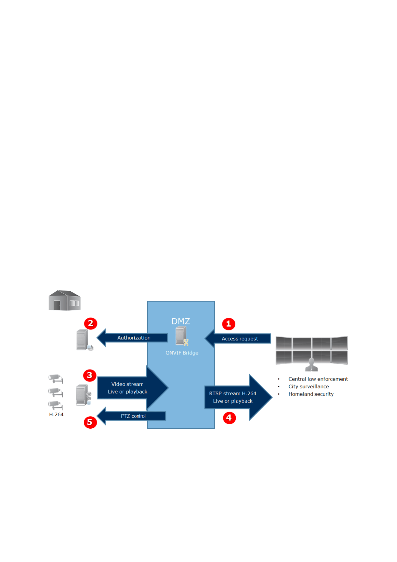
XProtect Professional VMS 2016 R3 - Administrator Manual
Advanced configuration
229
1. Create a Basic user in Management Application, or a Windows user in Active Directory.
2. Assign the user to a role that can access cameras, and specify permissions for the ONVIF
Bridges security group on the Overall Security tab for the role.
3. Assign the user to the Milestone ONVIF Bridge during installation, and in Management Client
or Management Application for each ONVIF client afterward.
Milestone ONVIF Bridge allows ONVIF clients only to request and receive video streams from
cameras. ONVIF clients cannot configure settings in the XProtect VMS system or the Milestone
ONVIF Bridge.
As a security precaution, Milestone recommends that you install the ONVIF Bridge server in a
demilitarized zone (DMZ). If you install the bridge in a DMZ, you must also configure port
forwarding for the internal and external IP addresses.
Milestone ONVIF Bridge architecture
The Milestone ONVIF Bridge is comprised of the following components:
Milestone ONVIF Bridge server
Milestone ONVIF Bridge 32-bit plug-in for Management Application
Milestone ONVIF Bridge 64-bit plug-in for Management Client
The following image shows a high-level view of the interoperability between an ONVIF client, the
Milestone ONVIF Bridge, and XProtect VMS.
XProtect VMS
ONVIF clients
1. An ONVIF client connects to the XProtect VMS via the ONVIF Bridge server through
Internet. To do this, the ONVIF client needs IP address or domain name
(domain/hostname) of the server where Milestone ONVIF Bridge is installed, and the ONVIF
port number.
2. The ONVIF Bridge server connects to the management server to authorize the ONVIF client
user.

XProtect Professional VMS 2016 R3 - Administrator Manual
Advanced configuration
230
3. After authorization, the recording server starts sending H.264 video streams from the
cameras to the ONVIF Bridge server.
Note: If a camera supports multiple streams, only the default stream is sent.
4. The ONVIF Bridge server sends the video as RTSP streams to the ONVIF client.
5. If available, the ONVIF client user can pan-tilt-zoom PTZ cameras.
Note: Milestone recommends that you install the ONVIF Bridge server in a demilitarized zone
(DMZ).
Licensing
Milestone ONVIF Bridge does not require additional licenses. You can download and install the
software for free from the Milestone Systems website.
Installing Milestone ONVIF Bridge
When you install Milestone ONVIF Bridge, you install a server and a plug-in for the Management
Application, which are the central administration components for XProtect Advanced VMS, and
XProtect Professional VMS products, respectively. For example, you use these components to
manage cameras, set up users, grant permissions, and so on.
You can install and add one or more Milestone ONVIF Bridges to your system. However, this
increases the load on the network, and can impact performance. Typically, only one Milestone
ONVIF Bridge is added to a system because multiple ONVIF clients can connect via one bridge.
Supported versions of XProtect video management software and
Milestone Husky products
You can use the Milestone ONVIF Bridge with any version of XProtect video management software
or Milestone Husky product.
System requirements
The computer where you want to install the Milestone ONVIF Bridge server component must have
access to the Internet, and the following software installed:
Microsoft® .NET Framework 3.5.
Microsoft® .NET Framework 4.5.1 or higher.
Visual C++ Redistributable Package for Visual Studio 2013 (x64).
Important: Cameras must support H.264 streaming via the Internet.
What's installed?
During installation, the following components are installed:
Milestone ONVIF Bridge server, including the Milestone ONVIF Bridge service, the Milestone
RTSP Bridge service, and the Milestone ONVIF Bridge Manager.
Milestone ONVIF Bridge plug-in. The plug-in will be available in the Servers node in
Management Application. This happens automatically if you use a Typical installation
method. If you use a Custom installation method, you install it in a second step.

XProtect Professional VMS 2016 R3 - Administrator Manual
Advanced configuration
231
Installation also does the following:
Registers and starts the Milestone ONVIF Bridge service and the Milestone RTSP Bridge
service
Starts the Milestone ONVIF Bridge Manager, which is available in the Windows notification
area on the server where the ONVIF Bridge Server is installed
Note: The actions in the ONVIF Bridge Manager apply to both the Milestone ONVIF Bridge service
and the Milestone RTSP Bridge service. For example, when you start or stop the ONVIF Bridge
service, the Milestone RTSP Bridge service also starts or stops.
Before you begin
Before you start the installation, get the following information:
The domain name and password for the dedicated user account that was created for the
Milestone ONVIF Bridge. For more information, see the section titled Milestone ONVIF
Bridge security controls (see "About Milestone ONVIF Bridge" on page 227).
The URL or IP address, and the port number, of the management server.
You will need this information during installation.
Install the Milestone ONVIF Bridge
Download the installation file:
1. On the computer where you want to install Milestone ONVIF Bridge, go to the Milestone
website https://www.milestonesys.com/support/download-software/ and locate the
Milestone ONVIF Bridge product.
2. Click the Milestone ONVIF Bridge installer file.
3. Select Run or Save and follow the instructions.
Run the installer:
1. Select the language you want to use, and then click Continue.
2. Read and accept the license agreement, and then click Continue.
3. Select the installation type, as follows:
To install the ONVIF Bridge server and plug-in on one computer, and apply default
settings, click Typical. Go to step 7.
To install the ONVIF Bridge server and plug-in on separate computers, click Custom.
Use this method if you have a distributed system. If you choose Custom, select the
server option, and then click Continue.
4. To establish a connection to management server, specify the following:
The URL or IP address, and the port number, of the management server. The default
port is 80. If you omit the port number, the system will use port 80.
The domain user name and password of the Windows user or Basic user that the service
will use. Click Continue.
Note: Leave User account in the Log in as field.

XProtect Professional VMS 2016 R3 - Administrator Manual
Advanced configuration
232
5. Select the file location and product language, and then click Install.
6. When the installation is complete, a list of successfully installed components displays.
Depending on the installation method you chose, do one of the following:
If you selected a Typical installation, click Close.
If you chose Custom, click Close, and then install the ONVIF Bridge plug-in on the
computer where Management Application is installed. To install the plug-in, run the
installer again on that computer.
The following components are now installed:
Milestone ONVIF Bridge server.
Milestone ONVIF Bridge plug-in that is visible in Management Application in the Servers
node.
Milestone ONVIF Bridge Manager that is running and accessible from the notification area
on the server with the ONVIF Bridge server installed.
Milestone ONVIF Bridge service that is registered as a service.
You are ready for initial configuration (see "Configuring the Milestone ONVIF Bridge" on page 232).
Configuring the Milestone ONVIF Bridge
After you install the Milestone ONVIF Bridge, the ONVIF Bridge service is running and the icon in
the system tray turns green. The next steps are to:
Add the ONVIF Bridge plug-in to the Management Application
Enable ONVIF clients to access your XProtect video management software product
Add a Milestone ONVIF Bridge to the Management Application
1. Open the Management Application.
2. Expand Servers, right-click ONVIF Bridge, and select Add New.
3. Enter a name for the Milestone ONVIF Bridge, and then click OK.
Configure user settings for an ONVIF client
Before you can complete these steps, you must have already created a basic user in Management
Application, or a Windows user in Active Directory for the ONVIF client. The user must be assigned
to a role that has permission to view cameras and access the Milestone ONVIF Bridge. For more
information, see the section titled "Milestone ONVIF Bridge security controls" in About Milestone
ONVIF Bridge (on page 227). For information about how to set up a basic user in Management
Application, see the Help for those programs.
To provide an ONVIF client access to your XProtect video management software, follow these
steps:
1. Open the Management Application.
2. Expand Servers, select ONVIF Bridge, and then select the bridge you just added.
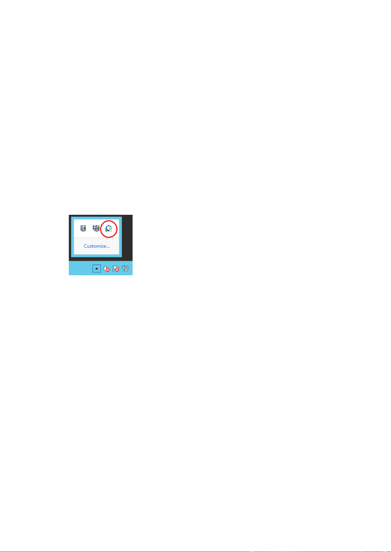
XProtect Professional VMS 2016 R3 - Administrator Manual
Advanced configuration
233
3. On the User settings tab, enter the domain user name (domain/user) and the password of
the dedicated user created for the ONVIF client.
4. Click the Add user button.
The name of the ONVIF client user appears in the list of ONVIF user credentials.
Managing Milestone ONVIF Bridge
After you configure Milestone ONVIF Bridge, you can monitor the service and change configuration
settings in several ways.
Check the status of the ONVIF Bridge service
To view the status of the ONVIF Bridge service, follow these steps.
1. On the computer where the ONVIF Bridge server is installed, look in the notification area.
The ONVIF Bridge tray icon indicates the status of the ONVIF Bridge service. If the service
is running, the icon is green.
2. If it is not running, the icon is yellow or red. Right-click the icon and select Start ONVIF
Bridge service.
View logs
The ONVIF Bridge Manager saves log information about the ONVIF Bridge server and the RTSP
streams.
1. In the notification area on the computer where the ONVIF Bridge server installed, right-
click the ONVIF Bridge tray icon.
2. Select Show latest ONVIF log or Show latest RTSP log.
Change the level of information in your logs
The ONVIF Bridge Manager saves log information about the ONVIF Bridge server and the RTSP
streams.
To change the level of information, follow these steps:
1. Right-click the ONVIF Bridge tray icon, and then stop the ONVIF Bridge service.
2. Right-click the ONVIF Bridge tray icon again, and select Configuration.
3. In the Log level for ONVIF and Log level for RTSP fields, specify the type of
information, and how much information, you want to save in your ONVIF and RTSP logs.
The default value is Information.
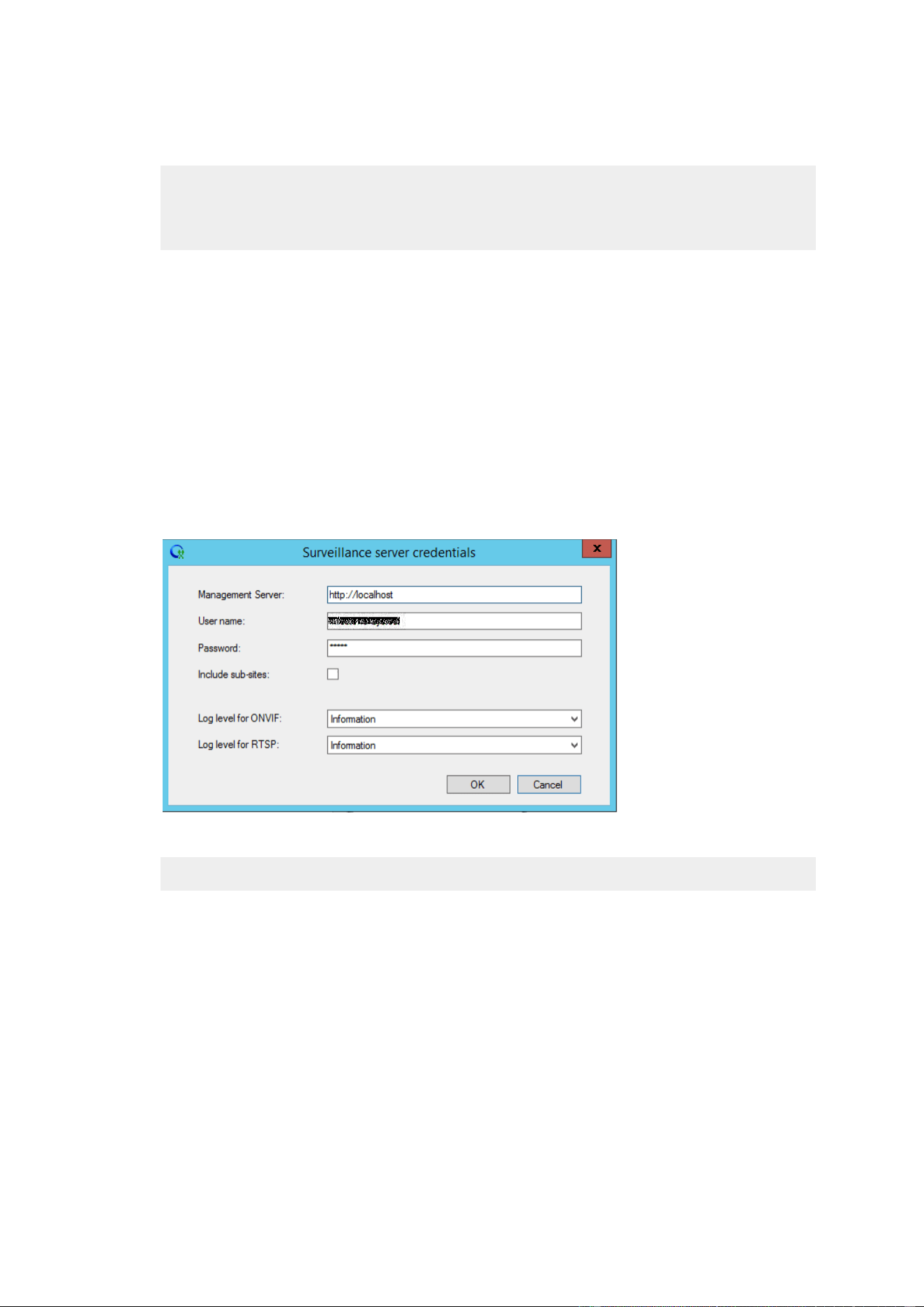
XProtect Professional VMS 2016 R3 - Administrator Manual
Advanced configuration
234
Note: From top to bottom in the list, the options are ordered from lowest level to highest
level. Each level includes the level above it in the list. For example, the Warning level
includes the Error level. If you can, only use the Error, Warning, and Information levels.
The Trace and Message levels capture more information and use more disk space, which
can decrease performance.
4. Click OK.
5. Right-click the ONVIF Bridge tray icon, and then start the ONVIF Bridge service.
Change configuration settings for the Milestone ONVIF Bridge
If you change the IP address or host name of the surveillance server, or if you have changed the
user accounts that have access to the surveillance server service, you must update this information
for Milestone ONVIF Bridge.
To change the VMS address or login credentials, follow these steps:
1. On the computer where Milestone ONVIF Bridge server is installed, right-click the ONVIF
Bridge tray icon, and then stop the ONVIF Bridge service.
2. Right-click the ONVIF Bridge tray icon again, and select Configuration.
3. Specify the new information, and then click OK.
Note: You must use the fully qualified domain name or the IP address of the server where
the management server is installed.
4. Right-click the ONVIF Bridge tray icon, and then start the ONVIF Bridge service.
The ONVIF Bridge service is now running and the tray icon turns green.
Including sub-sites
By default, the Milestone ONVIF Bridge is configured to exclude sub-sites. This means that ONVIF
client users cannot access video from cameras that are installed on sub-sites.
You can change this to include sub-sites. However, Milestone recommends that you do so only for
systems where sub-sites do not contain large numbers of cameras The Milestone ONVIF Bridge
aggregates and displays all cameras, including those from sub-sites, in one list. For example, if the
system and sub-sites have more than 50 cameras, the list will be difficult to use.

XProtect Professional VMS 2016 R3 - Administrator Manual
Advanced configuration
235
Tip: If you must include sub-sites, consider installing the Milestone ONVIF Bridge on each
management server. You will have more than one list of cameras, however, the cameras will be
easier to identify and navigate.
To include sub-sites:
1. Right-click the ONVIF Bridge tray icon, and then stop the ONVIF Bridge service.
2. Right-click the ONVIF Bridge tray icon again, and click Configuration.
3. Select the Include sub-sites checkbox, and then click OK.
4. Right-click the ONVIF Bridge tray icon, and then start the ONVIF Bridge service.
Tips and tricks
The configuration created by ONVIF Bridge Manager is stored locally in a file at
ProgramData\Milestone\Milestone ONVIF Bridge. The name of the file is serverconfiguration.xml. If
this file is deleted, you must update the configuration in the ONVIF Bridge Manager.
To update a configuration, follow the steps described in the section of this document titled Change
configuration settings for a Milestone ONVIF Bridge.
Milestone ONVIF Bridge properties
This section provides information about the settings for managing users and connections, and
configuration settings for cameras.
User settings tab (properties)
The following table describes the settings for the ONVIF Bridge server and ONVIF clients.
Name
Description
ONVIF port
The port number of the ONVIF port. ONVIF clients use this port to
connect to the ONVIF Bridge server.
The default port number is 580.
RTSP port
The port number of the RTSP port. The ONVIF Bridge server
sends RTSP video streams through this port to ONVIF clients.
The default port number is 554.
ONVIF user credentials
Lists the ONVIF client users that have access to the XProtect VMS
system through the ONVIF Bridge server.
User name
The domain user name of the user created for an ONVIF client.
Prerequisite: You have set up the ONVIF client users as users in
Management Application with access to cameras and the
Milestone ONVIF Bridge.
Password
The password for the ONVIF client user.
Add user
After you enter a domain user name and password, click the Add
user button to add the user.
Remove user
Prevent an ONVIF client from accessing the Milestone ONVIF
Bridge. Remove a selected user from the ONVIF user
credentials list.

XProtect Professional VMS 2016 R3 - Administrator Manual
Advanced configuration
236
Advanced settings tab (properties)
The advanced settings for the ONVIF Bridge list the default settings for all cameras that the ONVIF
Bridge provides to the ONVIF clients when the clients connect and request video streams.
The settings do not reflect the actual configuration of the cameras, and do not affect the video
stream. The system uses the settings to speed up the exchange of video between the ONVIF
Bridge and the ONVIF client. The ONVIF client will use the actual settings from the RTSP stream.
You can change the default settings that ONVIF Bridge provides to the ONVIF client, for example, if
you want the values to reflect the actual configuration of the cameras.
Name
Description
Max days of retention
Default value is 30.
Frame per seconds
Default value is 5.
Width
Default value is 1920. This corresponds to full HD quality.
Height
Default value is 1080. This corresponds to full HD quality.
Bitrate Kbps
Default value is 512.
GOP size
Default value is 5.
Codec
Select one of the H.264 codec profiles. The default value is H.264
Baseline Profile.
Use configurations from
cameras
Enable this to use the actual configuration of the cameras instead
of the default average values defined above.
Note: If you enable this setting, the response time between the
XProtect system and the ONVIF clients increases.
Using ONVIF clients to view video streams
ONVIF clients can be many different things, ranging from advanced custom surveillance systems to
basic media players.
This section provides examples of how to connect a Network Video Client and a media player to the
Milestone ONVIF Bridge.
Use a Network Video Client to view a live stream
This example describes how to install the ONVIF Device Manager, and configure it to stream live
video from an XProtect Advanced VMS installation.
The ONVIF Device Manager is a free, open source Network Video Client from iDeviceDesign that
complies with ONVIF standards. The tool is widely used to because it makes it easy to discover and
view video from ONVIF compliant cameras on a network. Note, however, that you use ONVIF
Device Manager to stream only live video. Additionally, you cannot capture and save the video data
in the stream.
Before you start, get the following information from the person who administrates the XProtect
Advanced VMS installation:
The login credentials for the user that was created for the Milestone ONVIF Bridge

XProtect Professional VMS 2016 R3 - Administrator Manual
Advanced configuration
237
The IP address or computer name of the computer where the Milestone ONVIF Bridge is
installed
To install the ONVIF Device Manager, follow these steps:
1. Go to https://sourceforge.net/projects/onvifdm (https://sourceforge.net/projects/onvifdm),
and then download and run the installer. You can install the ONVIF Device Manager on any
computer.
2. When the installation completes, an icon is available on your desktop. Double-click the icon
to start the ONVIF Device Manager.
3. When you start the ONVIF Device Manager, it automatically discovers ONVIF compliant
devices on the network. However, it might not discover the Milestone ONVIF Bridge.
If it does, go to step 6.
If it does not, add the bridge manually. Continue with step 4.
4. To add a Milestone ONVIF Bridge, click ADD.
5. In the Add device dialog box, in the URI field, provide the name or IP address of the
computer where the Milestone ONVIF Bridge is installed, and the ONVIF port number. For
example, the string should look like this: http://<IP address>:580/onvif/device_service.
6. After you add the bridge, it is available at the bottom of the Device list. Select it.
7. Enter the login credentials for the basic user that was created for the ONVIF client above
the list. For the user name, you must enter the domain user name.
8. Restart the ONVIF Bridge service to apply the change.
Alarms
About alarms
Available functionality depends on the system you are using. See the Product comparison chart (on
page 11) for more information.
The Alarms feature is a MIP-based feature that uses functionality handled by the event server. It
provides central overview and control of alarms in any number of system installations throughout
your organization.
You can configure alarms to be generated based on either:
Internal events (system-related): for example, motion, server responding/not
responding, archiving problems, lack of disk space, and more.
External events (integrated): for example, MIP plug-in events.
The Alarms feature also handles general alarms settings and alarm logging.
Configuring alarms
An alarm configuration may include:
Dynamic setup of alarm handling based on users access rights
Central overview of all components: servers, cameras, and external units

XProtect Professional VMS 2016 R3 - Administrator Manual
Advanced configuration
238
Setup of central logging of all incoming alarms and system information
Handling of plug-ins, allowing customized integration of other systems, for example
external access control systems.
Viewing alarms
The following can play a role with regards to alarms and who can view/control/manage them and
to what degree. This is because alarms are controlled by the visibility of the object causing the
alarm.
Source/device visibility: if the device causing the alarm is not set to be visible to the user,
the user cannot see the alarm in the alarm list in XProtect Smart Client.
Right to trigger manually defined events: if manually defined events are available in your
system, these can determine if the user can trigger selected manually defined events in
XProtect Smart Client.
External plug-ins: if any external plug-ins are set up in your system, these may control
user's rights to handle alarms.
General access rights: can determine whether the user is allowed to (only) view or also to
manage alarms.
Time profiles for alarms
Alarms can be based on time profiles (for alarms) (see "Add a time profile (for alarms)" on page
239). Time profiles for Alarms are periods of time to use when you create alarm definitions. You
can, for example, create a time profile for alarms covering the period from 2.30 PM till 3.30 PM on
Mondays and use that time profile to make sure that certain alarm definitions are only enabled
within this period of time.
Alarms and XProtect Smart Client
Alarms appear in the alarm list in XProtect Smart Client. Here, you can view and manage alarms to
ease overview and to delegate and handle alarms. You can, for example reassign alarm, change
their status or comment on alarms.
You can integrate alarms with the map functionality (see "About maps" on page 239). The Alarms
feature is a powerful monitoring tool, providing instant overview of alarms and possible technical
problems.
Alarms and XProtect Central
The alarms feature covers almost the same functionality as XProtect Central and configuration of
XProtect Central functionality is now included in the alarms feature.
XProtect Central was an independent product consisting of two parts: a dedicated server and a
number of dedicated clients. Alarms, on the other hand, is an integrated part of your system. This
means that much configuration needed in XProtect Central has become redundant with the
introduction of Alarms. Client-wise, the Alarms feature uses XProtect Smart Client. However, you
must still configure the features Alarms, Time Profiles (for Alarms) and General Settings in the
Management Application. These features are very similar to XProtect Central. You cannot reuse old
alarm and map definitions from XProtect Central. You must redefine your alarms and maps
definitions in the Alarms feature.
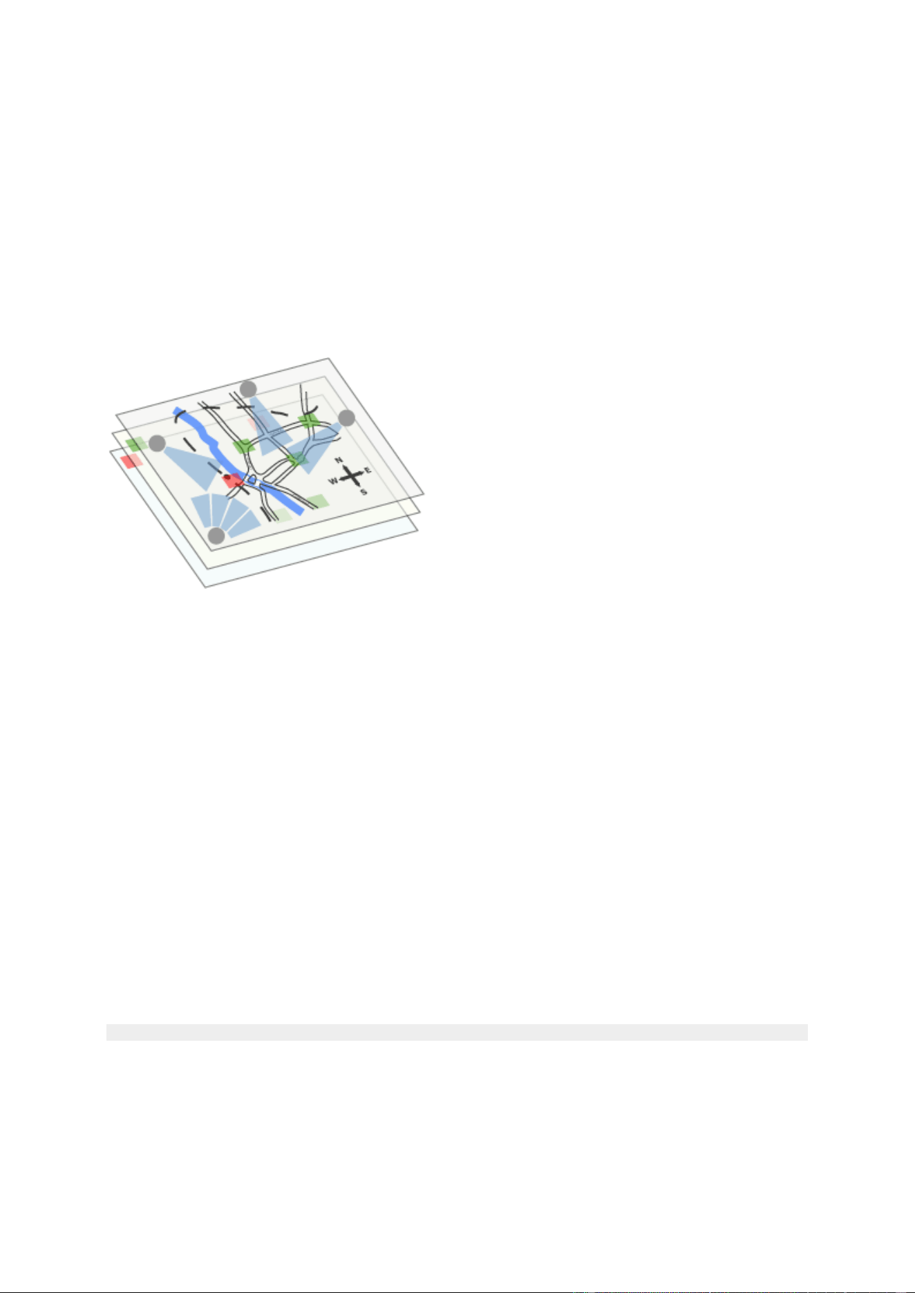
XProtect Professional VMS 2016 R3 - Administrator Manual
Advanced configuration
239
About maps
Available functionality depends on the system you are using. See the Product comparison chart (on
page 11) for more information.
With maps as an integrated part of alarms, you get a physical overview of your surveillance
system: with the possibility to assign cameras to a map, you can always tell where alarms
originate, which cameras are placed where, and in what direction are they pointing. Also, you can
use maps to navigate from large perspectives to detailed perspectives, and vice versa: for
example, a state map can have hot zones (small icons on the map) that point to more detailed
maps including cities, neighborhoods, streets and floor plans.
Example: Hierarchy of maps
All user-interaction with maps, including adding and maintaining maps, takes place in XProtect
Smart Client.
For detailed information, see the XProtect Smart Client documentation. In order to use maps, the
Event Server service must be running. The Event Server service is automatically included if you run
a Typical installation of your surveillance server installation (see "Install your system software" on
page 33).
Add an alarm
To add/configure an alarm:
1. Expand Alarms, right-click Alarm Definition and select Create New.
2. Specify required properties (see "Alarms definition" on page 240). Click OK.
3. Save your configuration changes by clicking Save in the yellow notification bar in the
upper-right corner of the Management Application.
For a detailed overview of Alarms and how the feature works, see About alarms (on page 237).
Add a time profile (for alarms)
Time profiles are periods of time used for the Alarms feature only.
To add a time profile for an alarm, do the following:
1. Expand Alarms, right-click Time Profiles, and select Create New. The small month
overview in the top right corner of the Time Profile Properties window can help you get a

XProtect Professional VMS 2016 R3 - Administrator Manual
Advanced configuration
240
quick overview of the time periods covered by the time profile, as dates containing
specified times are highlighted in bold.
2. In the calendar, select the Day View, Week View, or Month View tab, then right-click
inside the calendar and select either Add Single Time... or Add Recurring Time....
3. If you select Add Single Time..., specify Start time and End time. If the time is to cover
whole days, select the All-day event box.
—or—
If you select Add Recurring Time..., specify time range, recurrence pattern, and range of
recurrence. Click OK.
4. Save your configuration changes by clicking Save in the yellow notification bar in the
upper-right corner of the Management Application.
When you edit an existing time profile, remember that a time profile may contain more than one
time period, and that time periods may be recurring.
Analytics events are typically data received from external third-party video content analysis (VCA)
providers. An example of a VCA-based system could be an access control system.
Alarms properties
Alarms definition
When you configure Alarm definitions (see "Add an alarm" on page 239), specify the following:
Enable
Enables the Alarms feature.
Name
Enter a name. The alarm's name appears whenever the alarm is
listed.
Alarm names do not have to be unique.
Description
Enter a description (optional).
Triggering event
This first list shows both system-related events and events from
plug-ins (for example access control systems or similar).
From the second list, select the event message to use when the
alarm is triggered.
Sources
Select which cameras and/or other devices the event should
originate from in order to trigger the alarm. Plug-in defined
sources, for example license plate recognition, access control
systems and MIP-plugins appear in the list if installed.
Your options depend upon which type of event you have selected.
Time profile
If you select Time profile, you must select when the alarm
should be enabled for triggering. If you have not defined alarm
time profiles (see "Add a time profile (for alarms)" on page 239),
you will only be able to select Always. If you have defined one or
more time profiles, you can select them from this list.

XProtect Professional VMS 2016 R3 - Administrator Manual
Advanced configuration
241
Event based
If you select Event based, you must select which events should
start and stop the alarm. Events available for selection are
hardware events defined on cameras, video servers and input
(see "Overview of events and output" on page 108). You can also
use global/manual event definitions (see "Add a manual event"
on page 111).
Note that when you select Event based, you cannot define
alarms based on outputs—only on inputs.
Time Limit
Select the time-limit within which the operator must respond to
the alarm.
Events triggered
Select the event to be triggered if the operator does not react
within the time limit specified in Time limit. This could be, for
example, sending an email, SMS or similar.
Related cameras
Select (a maximum of 15) cameras for inclusion in the alarm
definition even though they are not themselves triggering the
alarm. This can be relevant, for example, if you have selected an
external event message (such as a door being opened) as the
source of your alarm. By defining one or more cameras near the
door, you could attach the cameras' recordings of the incident to
the alarm.
Related map
Select a map to associate with the alarm definition.
The selected map is automatically be shown in XProtect Smart
Client whenever the alarm is listed. This might help you to
quicker identify the physical location of the alarm.
Initial alarm owner
Select a default user responsible for the alarm. You can only
select from users allowed to view all cameras and/or other
devices selected as source(s) for the event causing the alarm.
Initial alarm priority
Select a priority (High, Medium or Low) for the alarm. Priorities
can be used for sorting purposes and workflow control in XProtect
Smart Client.
Initial alarm category
Select a category to which the alarm should initially be assigned.
This could be, for example, Building01, Burglary, ElevatorEast
or similar, depending on which categories have been defined.
Event triggered by alarm
Define an event to be triggered by the alarm in XProtect Smart
Client (if needed).
Auto-close alarm
Select if the alarm should automatically be closed upon a
particular event. This is possible for alarms triggered by some
(but not all) events.
See also Alarm data settings (on page 241) and Alarm sound settings (see "Sound settings" on
page 243) for further information on how to configure alarm settings.

XProtect Professional VMS 2016 R3 - Administrator Manual
Advanced configuration
242
Alarm data settings
When you configure alarm data settings, specify the following:
Alarm Data Levels tab, Priorities
Name
Description
Level
Add new priorities with level numbers of your choosing or
use/edit the default priority levels (numbers 1, 2 or 3). Use these
priority levels to configure the Initial alarm priority setting (see
"Alarms definition" on page 240).
Name
Type a name for the entity. You can create as many as you like.
Sound
Select the sound to be associated with the alarm. Use one if the
default sounds or add more in Sound Settings (on page 243).
Alarm Data Levels tab, States
Name
Description
Level
Add new states with level numbers of your choosing. The state
levels are only visible in the Alarm List in XProtect Smart Client.
You cannot edit or reuse the default state levels 1, 4, 9 and 11.
Name
Type a name for the entity. You can create as many as you like.
Alarm Data Levels tab, Categories
Name
Description
Level
Add new categories with level numbers of your choosing. These
category levels are used to configure the Initial alarm category
setting (see "Alarms definition" on page 240).
Name
Type a name for the entity. You can create as many as you like.

XProtect Professional VMS 2016 R3 - Administrator Manual
Advanced configuration
243
Alarm List Configuration tab
In Available columns, use > to select which columns should be available in the XProtect Smart
Client Alarm List. Use < to clear selection. When done, Selected columns should contain the
items to be included.
Reasons for Closing tab
Name
Description
Enable
Select to enable that all alarms must be assigned a reason for
closing before they can be closed.
Reason
Add reasons for closing that the user can choose between when
closing alarms. Examples could be "Solved-Trespasser" or
"False Alarm". You can create as many as you like.
Sound settings
When you configure Sound Settings, specify the following:
Sounds
Select the sound to be associated with the alarm. The list of
sounds contain a number of default Windows sounds. These
cannot be edited. However, you can add new sounds of the file
type .wav, but only if these are encoded in Pulse Code Modulation
(PCM).
Although the default sounds are standard Windows sound-files,
local Windows settings might cause these to sound different on
different machines. Some users might also have deleted one or
more of these sound-files and will therefore be unable to play
them. To ensure an identical sound all over, you should import
and use your own .wav files encoded in PCM.
Add
Add sounds to the system. Browse to the sound to upload one or
several .wav files.
Remove
Remove a selected sound from the list of manually added sounds.
You cannot remove default sounds.
Test
Lets you test the sound. In the list, select the sound. The sound
is played once.
Time profile
When you configure Time profiles (see "Add a time profile (for alarms)" on page 239), specify the
following:
Name
Type a name for the time profile.
Description
Enter a description (optional).

XProtect Professional VMS 2016 R3 - Administrator Manual
Advanced configuration
244
Add Single Time
Right-click the calendar and select Add Single Time. Specify
Start time and End time. If the time covers whole days, select
All-day event.
Add Recurring Time
Right-click the calendar and select Add Recurring Time. Specify
the time range, recurrence pattern, and range of recurrence.
Edit Time
Right-click the calendar and select Edit Time. Specify Start time
and End time. If the time covers whole days, select All-day
event.
When you edit an existing time profile, remember that a time
profile may contain more than one time period, and that time
periods may be recurring. If you want your time profile to contain
additional periods of time, add more single times or recurring
times.
MIP plug-ins
About MIP plug-ins
MIP plug-ins are add-ons you can install to your system. If you install a MIP plug-in, you can find
information about the plug-ins here. Some MIP plug-ins can be Milestone add-on products. If you
have installed an add-on product, you can also see the number of add-on product licenses you
have bought and how many of them you have activated.
You can assign MIP-related user rights to users and user groups. See Configure user and group
rights (on page 161).
XProtect Transact
XProtect Transact introduction
About XProtect Transact
Available functionality depends on the system you are using. See the Product comparison chart (on
page 11) for more information.
XProtect Transact is an add-on to Milestone's IP video surveillance solutions XProtect Advanced
VMS and XProtect Professional VMS.
XProtect Transact is a tool for observing ongoing transactions and investigating transactions in the
past. The transactions are linked with the digital surveillance video monitoring the transactions, for
example to help you prove fraud or provide evidence against a perpetrator. There is a 1-to-1
relationship between the transaction lines and video images.
The transaction data may originate from different types of transaction sources, typically point of
sales (PoS) systems or automated teller machines (ATM).
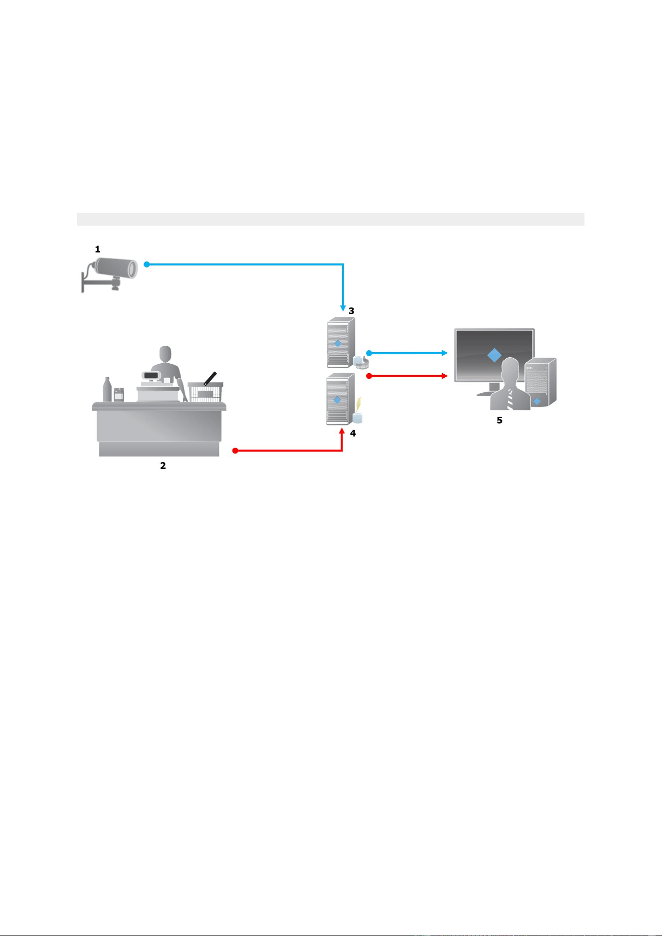
XProtect Professional VMS 2016 R3 - Administrator Manual
Advanced configuration
245
XProtect Transact system architecture
There are several components in the XProtect Transact communication flow. The input data
originates from the video surveillance cameras and the transaction sources providing the
transaction data, for example cash registers or ATMs. The transaction data is stored on the event
server, whereas the video stream is stored on the recording server. From the servers, the data is
passed on to XProtect Smart Client.
If you are using Advanced VMS, there may be several recording servers.
Illustration:
1 = Camera.
2 = Cash register.
3 = Recording server.
4 = Event server.
5 = Smart Client.
The blue arrows outline video recordings from the surveillance system.
The red arrows outline transaction data from the transaction sources.
By standard, XProtect Transact supports two types of transaction sources:
Serial port clients.
TCP server clients.
Additional types of transaction sources may be supported through custom connectors developed
with the MIP software development kit (SDK), for example a connector that retrieves transaction
data from an enterprise resource planning (ERP) system.

XProtect Professional VMS 2016 R3 - Administrator Manual
Advanced configuration
246
About connectors
A connector facilitates import of raw transaction data from the transaction source, for example the
ATM, into the event server associated with the video management software.
The built-in connectors available are described in the table:
Name
Description
TCP client connector
Use when the transaction source delivers the transaction data
through a TCP server interface. This connector has two settings
that you can specify: host name and port number.
Serial port connector
Use when receiving transaction data as input on a serial port on
the event server.
Connectors developed through the MIP software development kit may also be available.
See also
Add transaction source (wizard)
About transaction definitions
A transaction definition is a group of settings that help you control how raw data from the
transaction sources are displayed in XProtect Smart Client together with the video recordings. The
output is a reader-friendly format that resembles real-life receipts, for example till receipts and
receipts from automated teller machines.
More specifically, transaction definitions let you:
define when the individual transactions begin and end.
insert line breaks as required.
filter out unwanted characters or text strings, for example if the data comes from a printer
connection and contains unprintable characters for indicating line breaks, when to cut off a
till receipt.
substitute characters with other characters.
You can use the same transaction definition on multiple transaction sources.
See also
Add transaction definitions
About transaction events
A transaction event is the occurrence of specific words, numbers, or characters in the stream of
transaction data that flows from the transactions sources, for example the cash registers, to the
event server. As a system administrator, you need to define what the events are. This allows the
operator to track and investigate transaction events in XProtect Smart Client. For each event, a
method (match type) must be specified to identify strings in the transaction data: exact match,
wildcard, or regular expression.

XProtect Professional VMS 2016 R3 - Administrator Manual
Advanced configuration
247
See also
Define a transaction event (see "Define transaction events" on page 252)
Create a transaction alarm (see "Create alarms based on transaction events" on page 253)
Compatibility
XProtect Transact 2016 is compatible with version 2016 of these products:
XProtect Enterprise
XProtect Professional
XProtect Express.
Getting started
The XProtect Transact functionality is standard in Management Application. Before using the
XProtect Transact features in XProtect Smart Client, you should:
1. verify that your base license for XProtect Transact has been activated. In addition, verify
that you have a transaction source license for each transaction source that you need to
monitor. License information is available under the MIP Plugins node.
If you do not have the sufficient number of transaction source licenses, make sure that you
acquire additional licenses before the 30 days grace period expires.
2. add and configure the sources providing the transaction data, for example the cash
registers. For more information, see Add transaction source (wizard) (on page 248).
3. (optional) define the transaction events and potentially configure them to trigger rules or
alarms. In XProtect Smart Client, the operator can investigate the transaction events.
Even if you have not purchased any XProtect Transact licenses, you can try out XProtect Transact
with a trial license. For more information, see XProtect Transact trial license (on page 247).
See also
Setting up transactions
Setting up events (see "Setting up transaction events and alarms" on page 252)
XProtect Transact trial license
With an XProtect Transact trial license, you can try out the XProtect Transact functionality up to 30
days. All related features are enabled, and you can add one transaction source, for example a cash
register. When the 30 days trial period expires, all XProtect Transact features are deactivated,
including the Transact workspace and transaction view items. By purchasing and activating an
XProtect Transact base license and the transaction source licenses you need, you can use XProtect
Transact again, and your settings and data are maintained.
If you are using products from the Advanced VMS product suite, you need to acquire the trial
license from Milestone. The system administrator must activate the trial license in the
configuration.
If you are using products from the Professional VMS product suite, the trial license is a built-in
license. The trial license is activated when the system administrator adds a transaction source in
the configuration.

XProtect Professional VMS 2016 R3 - Administrator Manual
Advanced configuration
248
XProtect Transact configuration
Setting up transactions
In this section, you will learn how to add and configure the transaction sources, and how to create
the transaction definitions.
Add transaction source (wizard)
To connect data from a transaction source to XProtect Transact, you need to add the sources of the
transactions, for example an automated teller machine. In the wizard, you select a connector, and
you can connect one or more cameras.
If you do not have a transaction source license for the transaction source you are about to add, the
system will work during the 30-days grace period. Make sure that you acquire an additional
transaction source license and activate it in due time.
Steps:
1. In the Management Application's navigation pane, expand Transact.
2. Go to the Overview pane. Right-click the Transaction sources node and select Add
source. The wizard appears.
3. Follow the steps in the wizard.
4. Depending on the connector you select, different fields appear that you need to fill in. For
more information, see Transaction sources (properties) (on page 248). You can change
these settings after completing the wizard.
5. If the transaction definition you need is not available, click Add new to create a new
transaction definition.
See also
Add transaction definitions
About connectors
Transaction sources (properties)
The settings for transaction sources are described in the table.
Name
Description
Enable
If you want to disable the transaction source, clear this check
box. The stream of transaction data stops, but the data already
imported remains on the event server. You can still view
transactions from a disabled transaction source in XProtect Smart
Client during its retention period.
Even a disabled transaction source requires a transaction source
license.
Name
If you want to change the name, enter a new name here.

XProtect Professional VMS 2016 R3 - Administrator Manual
Advanced configuration
249
Name
Description
Connector
You cannot change the connector you selected when you created
the transaction source. To select a different connector, you need
to create a new transaction source, and during the wizard, select
the connector you want.
Transaction definition
You can select a different transaction definition that defines how
to transform the transaction data received into transactions and
transaction lines. This includes defining:
when a transaction begins and ends.
how transactions are displayed in XProtect Smart Client.
Retention period
Specify, in days, for how long transaction data is maintained on
the event server. The default retention period is 30 days. When
the retention period expires, automatically the data is deleted.
This is to avoid the situation, where the storage capacity of the
database is exceeded.
The minimum value is 1 day, whereas the maximum value is
1000 days.
TCP client connector
If you selected TCP client connector, specify these settings:
Host name: enter the host name of the TCP server
associated with the transaction source.
Port: enter the port name on the TCP server associated with
the transaction source.
Serial port connector
If you selected Serial port connector, specify these settings and
make sure that they match the settings on the transaction
source:
Serial port: select the COM port.
Baud rate: specify the number of bits transmitted per
second.
Parity: specify the method for detecting errors in the
transmissions. By default, None is selected.
Data bits: specify the number of bits used to represent one
character of data.
Stop bits: specify the number of bits to indicate when a byte
has been transmitted. Most devices need 1 bit.
Handshake: specify the handshaking method determining
the communication protocol between the transaction source
and event server.
See also
Add transaction source (wizard) (on page 248)
Add transaction definitions

XProtect Professional VMS 2016 R3 - Administrator Manual
Advanced configuration
250
Add transaction definitions
As part of defining a transaction source, you specify a definition for the source. A definition
transforms the raw data received into presentable data, so that users can view the data in XProtect
Smart Client in a format that matches real-life receipts. This is necessary, because typically the
raw data consists of a single string of data, and it can be difficult to see where the individual
transactions begin and end.
Steps:
1. In the Management Application's navigation pane, expand Transact.
2. Select Transaction definitions.
3. Go to the Overview pane. Right-click Transaction definition and select Add new. A
number of settings appear in the Properties section.
4. Use the Start pattern and Stop pattern fields to specify what data defines the start and
end of a receipt.
5. Click Start collecting data to collect raw data from the connected data source. The more
data you collect, the smaller the risk of missing characters, for example control characters,
you want to replace or omit.
6. In the Raw data section, highlight the characters you want to replace or omit. If you want
to type the characters manually, skip this step and click Add filter.
7. Click Add filter to define how the selected characters from the transaction source data are
displayed in XProtect Smart Client.
8. For each filter, select an action to determine how the characters are transformed. The
Preview section gives you a preview of how data is presented with the filters defined.
For detailed information about the fields, see Transaction definitions (properties).
You can also load previously collected data stored locally on your computer. To do this, click Load
from file.
Transaction definitions (properties)
The settings for transaction definitions are described in the table.
Name
Description
Name
Type a name.
Encoding
Select the character set used by the transaction source, for
example the cash register. This helps XProtect Transact convert
the transaction data to understandable text that you can work
with when configuring the definition.
If you select the wrong encoding, the data may appear as non-
sense text.
Start collecting data
Collect transaction data from the connected transaction source.
You can use the data to configure a transaction definition.
Wait for at least one, but preferably more, transactions to
complete.

XProtect Professional VMS 2016 R3 - Administrator Manual
Advanced configuration
251
Name
Description
Stop collecting data
When you have collected sufficient data to configure the
definition, click this button.
Load from file
If you want to import data from an already existing file, click this
button. Typically this is a file that you have created previously in
the file format .capture. It can be other file formats. What is
important here is that the encoding of the import file matches the
encoding selected for the current definition.
Save to file
If you want to save the collected raw data to a file, click this
button. You can reuse it later.
Match type
Select the match type to use to search for the start mask and the
stop mask in the collected raw data:
Use exact match: The search identifies strings that contain
exactly what you have entered in the Start mask and Stop
mask fields.
Use wildcards: The search identifies strings that contain what
you have entered in the Start mask and Stop mask fields in
combination with a wild card symbol (*, #, ?).
* matches any number of characters. For example, if you
have entered "Start tra*tion", the search identifies strings
that contain "Start transaction".
# matches exactly 1 digit. For example, if you have entered
"# watermelon", the search identifies strings that contain, for
example, "1 watermelon".
? matches exactly 1 character. For example, you may use the
search expression "Start trans?ction" to identify strings that
contain "Start transaction".
Use regular expression: Use this match type to identify
strings that contain specific notation methods or conventions,
for example a date format or credit card number. For more
information, see the Microsoft website
https://msdn.microsoft.com/en-
us/library/az24scfc(v=vs.110).aspx.
Raw data
Transaction data strings from the connected transaction source
are displayed in this section.
Start mask
Specify a start mask to indicate where a transaction begins.
Horizontal lines are inserted in the Preview field to visualize
where the transaction starts and ends, and will help to keep
individual transactions separated.
Stop mask
Specify a stop mask to indicate where a transaction ends. A stop
mask is not mandatory, but is useful if the received data contains
irrelevant information, such as information about opening hours
or special offers, between actual transactions.
If you do not specify a stop mask, the end of the receipt is
defined in terms of where the next receipt starts. The start is
determined by what is entered in the Start mask field.

XProtect Professional VMS 2016 R3 - Administrator Manual
Advanced configuration
252
Name
Description
Add filter
Use the Add filters button to point out the characters that you
want to be omitted in XProtect Smart Client or replaced by other
characters or a line break.
Replacing characters is useful when the transaction source string
contains control characters for non-printing purposes. Adding
lines breaks is necessary to make receipts in XProtect Smart
Client resemble the original receipts.
Filter text
Displays the characters currently selected in the Raw data
section. If you are aware of characters that you want to be
omitted or replaced, but they do not occur in the collected raw
data string, you can enter the characters manually in the
Character field.
If the character is a control character, you need to enter its
hexadecimal byte value. Use this format for the byte value: {XX}
and {XX,XX,...} if a characters consists of more bytes.
Action
For each filter you add, you should specify how the characters
you have selected are handled:
Omit: the characters you select are filtered out.
Substitute: the characters you select are replaced with the
characters you specify.
Add line break: the characters you select are replaced by a
line break.
Substitution
Type the text to replace the characters selected. Only relevant if
you have selected the action Substitute.
Preview
Use the Preview section to verify that you have identified and
filtered out unwanted characters. The output you see here
resembles what the real-life receipt looks like in XProtect Smart
Client.
See also
Add transaction definitions
Setting up transaction events and alarms
In this section, you will learn how to define the transaction events and set up alarms.
Define transaction events
To track and investigate transaction events in XProtect Smart Client, first you need to define what
the events are, for example the acquisition of a smartphone. You define transaction events on a
transaction definition, so that the events defined apply to all transaction sources, for example cash
registers, that use the transaction definition.
Steps:
1. In the Management Application's navigation pane, expand Transact.
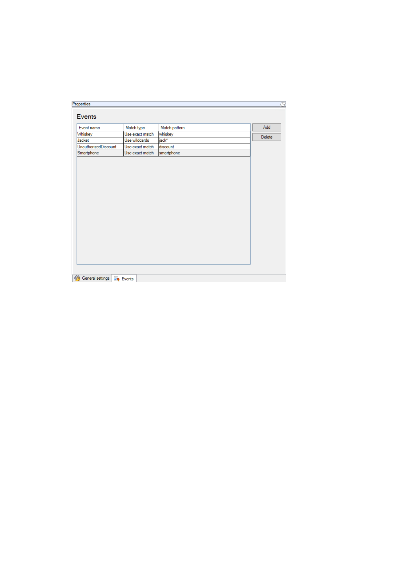
XProtect Professional VMS 2016 R3 - Administrator Manual
Advanced configuration
253
2. Go to the Overview pane. Select the transaction definition, where you want to define an
event.
3. Click the Events tab.
4. In the Properties pane, click Add. A new line is added.
5. Type a name for the event.
6. Select the match type to use to identify a specific string in the transaction data as an event.
You can choose between exact match, wildcard symbols, and regular expressions. For more
information, see the description of match type in Transaction definitions (properties).
7. In the Match pattern column, specify what you want the system to identify as an event,
for example "smartphone".
8. For each event, repeat the steps above.
See also
About rules and events
About transaction definitions (on page 246)
Create alarms based on transaction events
To notify the XProtect Smart Client operator whenever a specific transaction event occurs, first you
need to create a transaction alarm in Management Application. The alarm will appear on the Alarm
Manager tab in XProtect Smart Client allowing the operator to investigate the event and, if
required, take action.
Steps:
1. In the Management Application's navigation pane, expand Alarms.
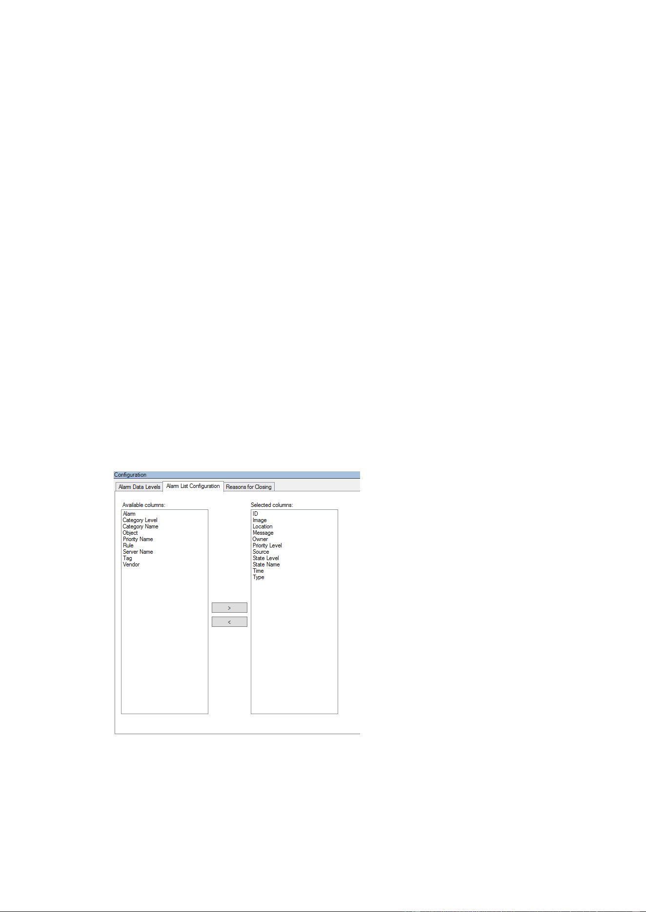
XProtect Professional VMS 2016 R3 - Administrator Manual
Advanced configuration
254
2. Go to the Overview pane. Right-click the Alarm Definitions node and select Add New....
The settings in the Properties pane become active.
3. Type a name for the alarm and, in the Description field, possibly also instructions for
XProtect Smart Client operator on what action to take.
4. In the Triggering event drop-down menu, select Transaction events.
5. In the drop-down menu below Transaction events, select the specific event.
6. In the Sources field, click the Select... button. A pop-up window appears.
7. Click the Servers tab and select the transaction source.
8. Specify additional settings. For more information, see Alarm Definitions.
See also
Define transaction events (on page 252)
Enable filtering of transaction events or alarms
If you want the XProtect Smart Client operator to be able to filter events or alarms by transactions,
first you need to enable the Type field in Management Application. Once enabled, the field is
available in the filter section on the Alarm Manager tab in XProtect Smart Client.
Steps:
1. In the Management Application's navigation pane, expand Alarms
2. Select Alarm Data Settings and click the Alarm List Configuration tab.
3. In the Available columns section, select the Type field.
4. Add the field to Selected columns.
5. Save the changes. Now, the field is available in XProtect Smart Client.

XProtect Professional VMS 2016 R3 - Administrator Manual
Advanced configuration
255
Maintaining transaction setup
In this section, you will learn how to edit, disable, and delete transaction sources.
Edit transaction source settings
After adding a transaction source, you can change the name or select a different transaction
definition. Depending on the connector selected, there may be additional settings you can modify,
for example the host name and port number of a connected TCP server. In addition, you can
disable a transaction source. This will interrupt the flow of transaction data from the transaction
source to the event server.
Once you have selected a connector, you cannot change it.
Steps:
1. In the Management Application's navigation pane, expand Transact.
2. Select Transaction sources.
3. Go to the Overview pane.
4. Make the required changes and save them. For more information, see Transaction sources
(properties) (on page 248).
See also
Add transaction source (wizard)
Disable transaction sources (on page 255)
Disable transaction sources
You can disable a transaction source, for example if an ATM is temporarily out of order, or a service
on a registered cash register is disabled. The flow of transaction data to the event server is
disrupted.
Steps:
1. In the Management Application's navigation pane, expand Transact.
2. Select Transaction sources.
3. Go to the Overview pane.
4. Clear the Enable check box and save the changes. The transaction source is disabled.
See also
Add transaction source (wizard)
Delete transaction source (see "Delete transaction sources" on page 255)
Delete transaction sources
You can delete the transaction sources you have added. The stored transaction data from that
source is deleted from the event server.

XProtect Professional VMS 2016 R3 - Administrator Manual
Advanced configuration
256
As an alternative, you can disable the transaction source to avoid that stored transaction data is
deleted. A disabled transaction source also requires a transaction source license.
Steps:
1. In the Management Application's navigation pane, expand Transact.
2. Select Transaction sources.
3. Go to the Overview pane. Click the Transaction sources item. Right-click the source you
want to delete.
4. Select Delete. A dialog box appears.
5. Click OK to confirm that you want to delete the transaction source.
See also
Add transaction source (wizard)
Verify XProtect Transact configuration
When you are done configuring XProtect Transact and its components, you can test that Transact
works as expected in XProtect Smart Client.
1. Verify that the all required transaction sources have been added correctly in Management
Application:
1. Open XProtect Smart Client and click the Transact tab.
2. Click the All sources drop-down menu and verify that all the transaction sources
appear.
2. Verify that the transaction definitions have been configured correctly in Management
Application. If configured correctly, there is one receipt per transaction, and the lines break
correctly:
1. Open XProtect Smart Client and click the Transact tab.
2. Select a transaction source that you know is active and click . The transaction lines
for today appear.
3. Click a line to view the associated receipt and video recordings.
3. Verify that transaction events are configured correctly:
1. Define a transaction test event in Management Application, for example an item that is
likely to be purchased and registered on a connected transaction source, for example a cash
register.
2. When the event has occurred, open XProtect Smart Client and click the Alarm
Manager tab.
3. Open the alarm list and select Event. The most recent events are displayed at the top
of the list. The test event you created should appear in the list.

XProtect Professional VMS 2016 R3 - Administrator Manual
Options
257
Options
About automatic device discovery
Automatic device discovery allows you to automatically add hardware devices to your system as
soon as you connect these to your network. When you enable automatic device discovery, your
system configures and sets up hardware devices automatically without the need for any user
interaction, making the hardware devices instantly accessible in XProtect Smart Client after the
automatic installation has completed.
Note that:
Not all hardware devices support automatic device discovery.
Hardware devices respond differently to automatic device discovery. The system adds some
hardware devices (such as Axis models P3301 and P3304) to the system automatically,
while you must turn off some devices from other vendors (such as Sony models SNC-
EB520, EM520 and E521) and back on again before they are automatically added to your
system.
If your system is not online, remember to activate your hardware device licenses offline.
Change default file paths
To change any of the default file paths:
1. If you want to change the configuration path, stop all services. This step is not necessary if
you want to change the default recording or archiving path.
2. Go to Options > Default File Paths...
3. You can now overwrite the necessary paths. Alternatively, click the browse button next to
the field and browse to the location. For the default recording path, you can only specify a
path to a folder on a local drive. If you are using a network drive, you cannot save
recordings if the network drive becomes unavailable.
If you change the default recording or archiving paths and there are existing recordings at
the old locations, you must select whether you want to move the recordings to the new
locations, leave them at the old locations, or delete them. Milestone recommends that you
choose to move the recordings to a new location.
4. Once changes are confirmed, restart all services.
About Customer Dashboard
Customer Dashboard is an online monitoring service that provides a graphical overview of the
current status of your system, including possible technical issues such as camera failures, to
system administrators or other people that have been given access to information about your
system installation.
You can select or clear the check box to change your Customer Dashboard settings at any time.

XProtect Professional VMS 2016 R3 - Administrator Manual
Options
258
Settings
General
In the General settings, you can change a number of settings that affect the general behavior and
look of the Management Application.
Customer Dashboard
Select if your system should send system information to the Customer Dashboard (see "About
Customer Dashboard" on page 257).
System mode
Important: Do not change system mode unless you are absolutely sure that you want the new
setting to be in effect immediately after saving.
At some point in time when you save recordings on your system, the storage you save recordings
on may become full. Your system offers you two system modes which handle this scenario
differently, Classic or Evidence collection.
Classic mode means that the system automatically deletes the oldest saved recordings in
order to make room for new recordings. This is how saved recordings have been handled so
far in all previous versions of your system. When you remove a hardware device in the
Management ApplicationManagement Application, recordings from the relevant device are
deleted from your storage. You can no longer play back recordings from the removed
camera in XProtect Smart Client as these recordings will be deleted from your storage.
Evidence collection mode means that the system stops recording when you reach full
storage capacity. All your old recordings are kept in the storage and the system does not
save any new recordings. This ensures that video recorded as evidence is never deleted
automatically and remains on the hard disk drive until you change system settings in your
system or you manually remove the recordings from your storage. Similarly, if you remove
a hardware device from the Management Application, recordings from the device are still
kept on your storage. You can playback recordings in XProtect Smart Client even if you
have removed the device in the Management Application.
Summary:
Classic mode
Evidence collection mode
When the storage on which
you are recording becomes
full
The system deletes oldest
recordings to make room for
new recordings.
The system stops saving new
recordings and keeps the oldest
recordings.
When you delete a device in
the Management Application
The system deletes all
recordings from the removed
device.
The system keeps all recordings
from the removed device.
Playback in XProtect Smart
Client
If you have removed the device
from the Management
Application, playback is no
longer possible in XProtect
Smart Client because the
system deletes recordings from
the device when you remove it.
Even if you have removed the
device from the Management
ApplicationManagement
Application, playback is still
possible in XProtect Smart
Client as the system keeps the
recordings.

XProtect Professional VMS 2016 R3 - Administrator Manual
Options
259
Classic mode
Evidence collection mode
Retention time
You can set and customize
retention time for your
recordings.
You cannot set retention time
for your recordings as your
system never deletes
recordings.
Choose a system mode that fits your system needs. Most users need the most recent recordings to
be available in their storage and should select Classic mode. Evidence mode provides an
alternative in cases where all recorded video is considered evidence and therefore must remain on
your storage.
Important: Evidence collection mode is only supported in XProtect Enterprise 2013+. If you run
your system in trial mode, only Classic mode is available.
Important: If you have upgraded from a previous version of your system, for example XProtect
Enterprise 8.1, Classic mode is the default selection in your system. You must manually change
your selection to use Evidence mode.
Language
The Management Application is available in several languages. From the list of languages, select
the language you want to use. Restart the Management Application to make the change of
language take effect.
User Interface
You can change the way the Management Application behaves.
Camera preview
Specify if you want to show live video or a snapshot when you
preview a camera in Management Application, or if you do not
want previewing at all.
Behavior settings
Specify how you want the Management Application to behave for
a number of actions, you and other Management Application
users perform.
The Management Application asks you to confirm many of the
actions. If you think this is not necessary, you can change the
behavior of the Management Application to not ask you again.
Examples of actions you can change:
When you attempt to delete a hardware device, should the
Management Application ask you to confirm that you want to
delete the hardware device, or should it delete the hardware
device straight away without asking?
Depending on the system you are using, you may have a limit
on the number of cameras you can use in your system. Select
if the system should warn you if you add more cameras than
the allowed number of cameras.
If your system should show live video when you preview
camera or if you would rather see a snapshot or no preview of
the camera.

XProtect Professional VMS 2016 R3 - Administrator Manual
Options
260
Restore Default Settings
Click this button if you want to restore all behavior settings to
their default values.
Connecting Hardware Devices
Automatic device discovery
Automatic device discovery (see "About automatic device discovery" on page 257) is turned off by
default in your system. Select the check box to enable this functionality.
If the discovered cameras must use another user name and password besides the camera's default
user name and password, select the Use the camera's default user name and password as
well as the following credentials check box and type the relevant credentials.
Not all devices support automatic device discovery. If your system does not detect your devices
and add them to your system, you must manually add the device.
Synchronize time on connected hardware devices
To ensure that the time stamp on connected hardware devices and the system is the same, enable
the use of time servers (see "About time servers" on page 15). If you hardware device do not link
up against a time server that ensures that the time on the hardware devices and the system is
synchronized, you risk that the system stops recording from the hardware devices all together.
Setting
Description
Use the recording server as
a time server
(Recommended)
The default system setting if you have upgraded from a previous
installation of the system's software.
Use the recording server to synchronize time between hardware
devices and your system.
Milestone recommends that you use this setting.
Use this Network Time
Protocol (NTP) server
Use an NTP server for time-synchronization instead of using the
recording server.
You must type the exact address of the NTP server to be able to
use it. Milestone recommends that you only use this setting if you
are an experienced system administrator.
Do not synchronize time on
connected hardware devices
The default setting if you have upgraded from a previous
installation of the system' software.
If you do not want any time synchronization to take place between
hardware devices and the system, use this setting.
Note that your hardware devices may stop recording if the system
notices a constant time drift between the hardware devices and the
system.

XProtect Professional VMS 2016 R3 - Administrator Manual
Options
261
IP address assignment settings
The system includes three different settings for assigning IP addresses to your hardware devices
when you connect them to the network. Each of the settings have their own advantages and
disadvantages. Note that not all cameras support the use of DHCP servers.
Setting
Description
Advantage
Disadvantage
Use of a DHCP
server to assign IP
addresses to
connected devices
Use a Dynamic Host
Configuration Protocol
(DHCP) server to
automatically assign IP
addresses to devices you
connect to the system.
If your system does not
use a DHCP server,
devices keep their pre-
assigned IP addresses or
use a self-configured IP
address which might not
work.
The DHCP servers keep
track of available IP
addresses and add
them to the devices
when they are added
to your network.
You can move devices
from one network to
another without having
to reconfigure them.
This is the default
system setting if you
have upgraded from a
previous installation of
the system's software.
Devices can change IP
addresses so that the IP
addresses in the
configuration do not
match anymore.
Do not assign an IP
address when
connecting a device
No IP addresses are
assigned to devices
connected to the system.
The devices keep their
current setup, for
example having a static
IP address or a DHCP-
assigned IP address.
Control everything
related to assigning IP
addresses yourself.
This is the default
system setting if you
have upgraded from a
previous installation of
the system's software.
You must keep track of
available IP addresses
yourself.
Assign a static IP
address to
connected devices
from this range:
A static IP address from
your indicated range is
assigned to each
individual device added to
the system.
Assigned IP addresses
never change.
You must reconfigure all
devices to change
network as devices
must be reconfigured
before you can move
them to another
network.
A Dynamic Host Configuration Protocol (DHCP) server is a standardized network protocol used on
IP networks for dynamically distributing network configuration parameters. With DHCP, devices
request IP addresses and networking parameters automatically from the DHCP server. The use of a
DHCP server reduces the need for a network administrator or a user to configure such settings
manually.
Default File Paths
Your system uses a number of default file paths. You can change the path of these if you need to.

XProtect Professional VMS 2016 R3 - Administrator Manual
Options
262
Default recording path for
new cameras
All new cameras you add use this path by default for storing
recordings.
If required, you can change individual cameras' recording paths
as part of their individual configuration (see "Recording and
archiving paths" on page 94), but you can also change the default
recording path so all new cameras you add use a path of your
choice.
Default archiving path for
new cameras
All new cameras you add use this path by default for archiving
(see "About archiving" on page 124).
If required, you can change individual cameras' archiving paths
as part of their individual configuration, but you can also change
the default recording path so all new cameras you add use a path
of your choice. Note that camera-specific archiving paths are not
relevant if you use dynamic path selection (see "Dynamic path
selection (properties)" on page 76) for archiving.
Configuration path
The default path used for storing your system configuration.
Access Control Settings
The use of XProtect Access requires that you have purchased a base license that allows you to
access this feature within your XProtect system. You also need an access control door license for
each door you want to control.
Specify the following Access Control Settings:
Name
Description
Show development property
panel
If selected, developer information is shown under Access Control
properties.
This setting is only meant to be used by developers of access
control system integrations.
Keep access control events
for:
Specify the number of days for which to keep access control
events. The default is 30 days. The value of 0 indicates that you
want to keep events indefinitely (server space permitting).
Audio Recording
Specify the default setting for audio recording when you add new cameras to the system.
Never
The system never records audio from your cameras.
Only when recording video
The system only records audio from your cameras when your
system is recording video.
Always
The system always records audio for your cameras.
You can change the setting later for each camera individually.

XProtect Professional VMS 2016 R3 - Administrator Manual
Options
263
Analytics Events (properties)
Analytics Events let you specify the following:
Enabled
Enable the analytics event feature.
Port
Specify the port used by this service. Default port is 9090.
Make sure that relevant VCA tool providers also use this port
number. If you change the port number, make sure that VCA tool
providers change their port number accordingly.
Events allowed from:
All network addresses or
Specified network addresses
Specify whether events from all IP addresses/host names are
accepted, or only events from IP addresses/host names specified
in a list:
In the Address list specify a list of trusted IP addresses/host
names that you want this service to recognize. The list is used to
filter incoming data so that only events from certain IP
addresses/host names are allowed. Both Domain Name System
(DNS) and IPv4 address formats are allowed in the list.
You have two ways of adding addresses to the list:
Manually: type the required IP address/host name in the
address list. Repeat for each required address.
Import an external list: read below.
Import
Click the Import... button to browse for the required external list
of addresses. To import an external list, save the list in a .txt file
format. Each IP address or host name must appear on a separate
line in the file.
Event Server Settings
Available functionality depends on the system you are using. See the Product comparison chart (on
page 11) for more information.
The event server has a number of settings that can change its behavior. You can specify the
following Event Server settings:
Keep closed alarms for
Specify the number of days you want the system to keep closed
alarms. Closed alarms are in the states Closed, Ignore, and
Reject.
This value is normally set to a low number to keep the capacity
requirements low, but you can define any number up to 99999
days, dependant on server space.
To keep closed alarms indefinitely, use the value 0 (dependant on
server space).

XProtect Professional VMS 2016 R3 - Administrator Manual
Options
264
Keep all other alarms for
Specify the number of days you want the system to keep all other
alarms, meaning alarms not in the states Closed, Ignore, and
Reject.
This value is normally set to a somewhat higher number, such as
30 days, but you can define any number up to 99999 days,
dependant on server space.
To keep all other alarms indefinitely, use the value 0 (dependant
on server space).
Keep logs for
Specify the number of days you want the system to keep the
Alarms log. Default is 30 days.
To keep logs indefinitely, use the value 0 (dependant on server
space).
Log server communication
Specify if you want to save a separate log for server
communication in addition to the regular log for the number of
days specified.
Important: Alarms often have associated video recordings. While the alarm information itself is
stored on the event server, the associated video recordings are fetched from the relevant
surveillance system server when users wish to view them. Therefore, if it is vital that you have
access to video recordings from all your alarms, make sure that video recordings from relevant
cameras are stored on relevant surveillance system servers for at least as long as you intend to
keep alarms on the event server.

XProtect Professional VMS 2016 R3 - Administrator Manual
System maintenance
265
System maintenance
Backing up and restoring configuration
About backup and restore of configuration
Milestone recommends that you make regular backups of your system configuration (cameras,
schedules, views, and so on) as a disaster recovery measure.
While it is rare to lose your configuration, it can happen under unfortunate circumstances. Luckily,
it takes only a minute to back up your existing configuration.
Back up system configuration
In the following, Milestone assumes that you have not changed your system's default configuration
path (see "Default File Paths" on page 261), which is C:\Program Data\Milestone\Milestone
Surveillance on servers running all supported operating systems. If you have changed the default
configuration path, you must take your changes into consideration when using the method
described in the following.
The backup described here is a backup of your entire surveillance system setup including log files,
event and Matrix configuration, restore points, view groups as well as Management Application and
XProtect Smart Client configuration. Alternatively, you can export your configuration as a backup
(see "Export and import Management Application configuration" on page 269), which is limited to
the Management Application configuration.
To back up:
1. Make a copy of the folder C:\Program Data\Milestone\Milestone Surveillance and all
of its content.
2. Open the folder C:\Program Files\Milestone\Milestone Surveillance\devices, and
verify if the file devices.ini exists. If the file exists, make a copy of it. The file exists if you
have configured video properties for certain types of cameras. For such cameras, changes
to the properties are stored in the file rather than on the camera itself.
3. Store the copies away from the server, so that they are not affected if the server is
damaged, stolen or otherwise affected.
Remember that a backup is a snapshot of your system configuration at the time of backing up. If
you later change your configuration, your backup does not reflect the most recent changes.
Therefore, back up your system configuration regularly. When you back up your configuration as
described, the backup includes restore points. This allows you to not only restore the backed-up
configuration, but also to revert to an earlier point in that configuration if you need to.
Restore system configuration
1. If you use the system on a server running any supported operating system, copy the
content of the backed-up Milestone Surveillance folder into C:\Program
Data\Milestone\Milestone Surveillance.

XProtect Professional VMS 2016 R3 - Administrator Manual
System maintenance
266
2. If you backed up the file devices.ini, copy the file into C:\Program
Files\Milestone\Milestone Surveillance\devices.
Back up and restore alarm and map configuration
Available functionality depends on the system you are using. See the Product comparison chart (on
page 11) for more information.
It is important that you regularly back up your alarm and map configurations. You do this by
backing up the event server, which handles your alarm and map configuration as well as the
Microsoft® SQL Server Express database, which stores your alarm data. This enables you to
restore your alarm and map configuration in a possible disaster recovery scenario. Backing up also
has the added benefit that it flushes the SQL Server Express database’s transaction log.
When you back up and restore alarm and/or map configuration, you must do it in the following
order:
Prerequisites
You must have administrator rights on the SQL Server Express database when you
back up or restore your alarm configuration database on the SQL Server Express. Once you
are done backing up or restoring, you only need to be a database owner of the SQL Server
Express database.
Microsoft® SQL Server Management Studio Express, a tool you can download for free
from the Microsoft website http://www.microsoft.com/downloads. Among its many features
for managing SQL Server Express databases are some easy-to-use backup and restoration
features. Download and install the tool on your existing surveillance system server and on a
possible future surveillance system server (you need it for backup as well as restoration).
Step 1: Stop the Event Server service
Stop the event server service to prevent configuration changes from being made:
1. On your surveillance system server, click Start > Control Panel > Administrative Tools
> Services.
2. Right-click the Event Server, click Stop.
This is important since any changes made to alarm configurations—between the time you create a
backup and the time you restore it—are lost. If you make changes after the backup, you must
make a new backup. Note that the system does not generate alarms while the Event Server service
is stopped. It is important that you remember to start the service again once you have finished
backing up the SQL database.
Step 2: Back up alarms data in SQL Server Express database
If you do not have SQL Server Management Studio Express, you can download it for free from
the Microsoft website http://www.microsoft.com/downloads.
1. Open Microsoft SQL Server Management Studio Express from Windows' Start menu by
selecting All Programs > Microsoft SQL Server 2008 > SQL Server Management
Studio Express.
2. When you open the tool, you are prompted to connect to a server. Specify the name of the
required SQL Server and connect with administrator user credentials. You do not have to
type the name of the SQL server: if you click inside the Server name field and select
<Browse for more...>, you can select the SQL Server from a list instead.

XProtect Professional VMS 2016 R3 - Administrator Manual
System maintenance
267
3. Once connected, you see a tree structure in the Object Explorer in the left part of the
window. Expand the SQL Server item, then the Databases item, which contains your entire
alarm configuration.
4. Right-click the VIDEOOSDB database, and select Tasks > Back Up...
5. On the Back Up Database dialog's General page, do the following:
Under Source verify that the selected database is VIDEOOSDB and that the backup
type is Full.
Under Destination A destination path for the backup is automatically suggested. Verify
that the path is satisfactory. If not, remove the suggested path, and add another path
of your choice.
6. On the Back Up Database dialog's Options page, under Reliability, select Verify
backup when finished and Perform checksum before writing to media.
7. Click OK to begin the backup. When backup is finished, you see a confirmation.
8. Exit Microsoft SQL Server Management Studio Express.
Step 3: Reinstall your system
Do not install your surveillance software on a mounted drive. A mounted drive is a drive that is
attached to an empty folder on an NTFS (NT File System) volume, with a label or name instead of a
drive letter. If you use mounted drives, critical system features may not work as intended. You do
not, for example, receive any warnings if the system runs out of disk space.
Before you start: Shut down any existing surveillance software.
1. Run the installation file. Depending on your security settings, you may receive one or more
security warnings. Click the Run button if you receive a warning.
2. When the installation wizard starts, select language for the installer and then click
Continue.
3. Select if you want to install a trial version of your system or indicate the location of your
software license file.
4. Read and accept the license agreement, and indicate if you want to participate in the
Milestone data collection program.
5. Select Typical or Custom installation. If you select Custom installation, you can select
application language, which features to install and where to install them. Let the installation
wizard complete.
You can now begin to configure your system, see Configure your system in Management
Application (see "Configure the system in the Management Application" on page 39).
Step 4: Restore alarms data in SQL Server Express database
Luckily, most users never need to restore their backed-up alarm data, but if you ever need to, do
the following:
1. In the Windows Start menu, open Microsoft SQL Server Management Studio Express.
2. Connect to a server. Specify the name of the required SQL Server, and connect using the
user account the database was created with.

XProtect Professional VMS 2016 R3 - Administrator Manual
System maintenance
268
3. In the Object Explorer on the left, expand SQL Server > Databases, right-click the
VIDEOOSDB database, and then select Tasks > Restore > Database...
4. In the Restore Database dialog, on the General page, under Source for restore, select
From device and click <Browse for more...>, to the right of the field. In the Specify
Backup dialog, make sure that File is selected in the Backup media list. Click Add.
5. In the Locate Backup File dialog, locate and select your backup file VIDEOOSDB.bak.
Then click OK. The path to your backup file is now listed in the Specify Backup dialog.
6. Back on the Restore Database dialog's General page, your backup is now listed under
Select the backup sets to restore. Make sure you select the backup by selecting the
check box in the Restore column.
7. Now go to the Restore Database dialog's Options page, and select Overwrite the
existing database. Leave the other options as they are, and then click OK to begin the
restoration. When the restore is finished, you see a confirmation.
8. Exit Microsoft SQL Server Management Studio Express.
Note: If you get an error message telling you that the database is in use, try exiting Microsoft SQL
Server Management Studio Express completely, then repeat steps 1-8.
Step 5: Restart the Event Server service
During the restore process, the Event Server service is stopped to prevent configuration changes
being made until you are done. Remember to start the service again:
1. On your surveillance system server, click Start > Control Panel > Administrative Tools
> Services.
2. Right-click the Event Server, click Start.
About the SQL Server Express transaction log and reasons for flushing it
Each time a change in the system's alarm data take place, the SQL Server logs the change in its
transaction log. The transaction log is essentially a security feature that makes it possible to roll
back and undo changes to the SQL Server Express database. The SQL Server by default stores its
transaction log indefinitely, and, therefore, the transaction log builds up more and more entries
over time.
The SQL Server's transaction log is by default located on the system drive, and if the transaction
log just keeps growing, it may in the end prevent Windows from running properly. Flushing the
SQL Server's transaction log from time to time is therefore a good idea, however flushing it does
not in itself make the transaction log file smaller, rather it prevents it from growing out of control.
Your system does not, however, automatically flush the SQL Server's transaction log at specific
intervals. This is because users have different needs. Some want to be able to undo changes for a
very long time, others do not care.
You can do several things on the SQL Server itself to keep the size of the transaction log down,
including truncating and/or shrinking the transaction log (for numerous articles on this topic, go to
support.microsoft.com http://support.microsoft.com and search for SQL Server transaction log).
However, backing up the system's database is generally a better option since it flushes the SQL
Server's transaction log and gives you the security of being able to restore your system's alarm
data in case something unexpected happens.

XProtect Professional VMS 2016 R3 - Administrator Manual
System maintenance
269
Export and import Management Application configuration
You can export the current configuration of your Management Application, either as a safety
measure in order to have a backup file of your configuration, or as a clone allowing you to use a
similar Management Application configuration elsewhere. You can, at a later time, import
previously exported Management ApplicationManagement Application configurations.
Export Management Application configuration as backup
With this option, all relevant Management Application configuration files are combined into one
single .xml file, which you can specify a location for. Note that if there are unsaved changes to your
configuration, these are automatically saved when you export the configuration.
1. In the File menu, select Export Configuration - Backup.
2. Browse to the location at which you want to store the exported configuration, specify a
suitable file name, and click Save.
If you intend to set up an identical version of your surveillance system elsewhere, do not export
your configuration as backup, since this may lead to the same device information being used
twice, in which case clients may get the following error message: Application is not able to start
because two (or more) cameras are using the same name or ID. Instead, export your
configuration as a clone. When you export as a clone, the export takes into account the fact that
you are not using the exact same physical cameras, etc. even though your new system may
otherwise be identical to your existing one.
Note that there is a difference between this Management Application configuration backup and the
system configuration backup done from the Milestone Surveillance folder because these are two
different things. The backup described here is limited to a backup of the Management Application
configuration. The type of system configuration backup done from the Milestone Surveillance folder
is a backup of your entire surveillance system setup (including, among other things, log files, event
configuration, restore points, view groups as well as the Management Application and XProtect
Smart Client configuration).
Export Management Application configuration as clone
With this option, all relevant Management Application configuration files are collected, and GUIDs
(Globally Unique IDentifiers, unique 128-bit numbers used for identifying individual system
components, such as cameras) are marked for later replacement. GUIDs are marked for later
replacement because they refer to specific components (cameras and so on). Even though you
wish to use the cloned configuration for setting up a new similar system using similar types of
cameras, the new system does not use the exact same physical cameras as the cloned system.
When you use the cloned configuration later in a new system, the GUIDs are replaced with GUIDs
representing the specific components of the new system.
After you have marked GUIDs for replacement, the configuration files are combined into one single
.xml file, which you can then save at a location specified by you. Note that if there are unsaved
changes to your configuration, they are automatically saved when you export the configuration.
1. In the File menu, select Export Configuration - Clone.
2. Browse to the location at which you want to store the exported configuration, specify a
suitable file name, and click Save.
Import previously exported Management Application configuration
The same import method is used regardless of whether the Management Application configuration
was exported as a backup or a clone.

XProtect Professional VMS 2016 R3 - Administrator Manual
System maintenance
270
1. In the File menu, select Import Configuration.
2. Browse to the location from which you want to import the configuration, select the relevant
configuration file, and click Open.
3. Only relevant if the system into which you import the configuration contains devices
(cameras, etc.) which are not present in the imported configuration: you are asked whether
you want to delete or keep recordings from affected devices. If you want to keep the
recordings, note that they are not accessible until you add the affected devices to the
system again. Select the option you need, and click OK.
4. Expand Advanced Configuration > Services.
5. For the Recording Server and Image Server services respectively, click the Restart button.
Restarting the two services applies the imported Management Application configuration.
Restore system configuration from a restore point
Restore points allow you to return to a previous configuration state. Each time you apply a
configuration change in the Management Application, a new restore point is created.
All restore points in the current and previous five sessions are stored and can be selected again. A
new session begins each time you start the Management Application as well as each time you save
the whole configuration. For sessions older than the last five sessions, only the latest restore point
of each session is stored. With the Number of old sessions to keep field, you can control how
many old sessions are kept.
When you select to restore a configuration from a restore point, the configuration from the selected
restore point is applied and used once the services are restarted.
If you have added new cameras or other devices to the system after the restore point was created,
they are missing if you load the restore point. This is because they were not in the system when
the restore point was created. In such cases, you are notified and must decide what to do with
recordings from the affected devices.
1. From the File menu, select Load Configuration from Restore Point...
2. In the left part of the Restore Points dialog, select the relevant restore point.
3. Click the Load Restore Point button.
4. If you are sure that you want to overwrite the current configuration with the one from the
selected restore point, click OK.
5. Only relevant if the current configuration contains cameras or other devices which were not
present in the selected restore point: you are asked whether you want to delete or keep
recordings from affected devices. If you keep the recordings, note that you cannot access
them until you add the affected devices to your system again. Select the relevant option,
and click OK.
6. Click OK in the Restore Points dialog.
7. Expand Advanced Configuration, and select Services.
8. For the Recording Server and Image Server services respectively, click the Restart button.
When the two services are restarted, the configuration from the selected restore point is
applied.

XProtect Professional VMS 2016 R3 - Administrator Manual
System maintenance
271
Note: When you select a restore point, you can see information about the configuration state at
the selected point in time in the right part of the dialog. This can help you select the best possible
restore point.
Importing changes to configuration
About importing changes to configuration
You can import changes to a configuration. This can be relevant if you install many similar systems,
for example in a chain of shops where the same types of server, hardware devices, and cameras
are used in each shop. In such cases, you can use an existing configuration as a template for the
other installations.
Since such installations are not exactly the same, as the hardware devices and cameras are of the
same type, but they are not physically the same, and therefore they have different MAC addresses,
there is an easy way of importing changes to the template configuration. You can import changes
about hardware devices and cameras as comma-separated values (CSV) from a file.
See Import changes to configuration (on page 272) for a step-by-step guide and About required
fields for CSV files when you import changes to configurations (on page 271) for which fields you
must include in the CSV files.
When you import changes, no hardware detection takes place nor does the software change the
camera's hardware capabilities. For example, if you replace a PTZ camera with a non-PTZ camera,
the software continues to show the replaced camera as a PTZ camera.
About required fields for CSV files when you import
changes to configurations
The CSV file must have a header line (determining what each value on the following lines is about),
and the following lines must each contain information about one hardware device only. The field
names are case sensitive, so you should ensure that you have written the fields exactly as shown
below.
For each hardware device, the following information is required:
HardwareOldMacAddress
Used to find the device that is going to have its properties
changed. This is a mandatory field that you must enter in order to
be able to import changes to the configuration from a CSV file.
HardwareNewMacAddress
The new IP address for the hardware device.
HardwareAddress
The IP address of the hardware device.
HardwarePort
The port for the hardware device.
HardwareUserName
The user name for hardware device's administrator account.
HardwarePassword
The password for hardware device's administrator account.
HardwareDriverID
If cameras and server are offline: specify a HardwareDriverID
for each hardware device you want to add.
Example: ACTi ACD-2100 105 indicates that you should use
105 as the ID if adding an ACTi ACD-2100 hardware device.

XProtect Professional VMS 2016 R3 - Administrator Manual
System maintenance
272
When you import changes, no hardware detection takes place and no hardware functionality is
changed. For example, if you replace a PTZ device with a device that does not have PTZ
functionality, the new device still lists as a PTZ device.
The following applies for the information present in CSV files:
The first line of the CSV file must contain the headers, and following lines must contain
information about one hardware device each
Separators can be commas, semicolons or tabs, but you cannot mix them
All lines must contain valid values. All camera names, user names and similar items must
be unique, and cannot contain any of the following special characters: < > & ' " \ / :
* ? | [ ]
There is no fixed order of values, and you can omit optional parameters entirely
Import changes to configuration
1. From the menu bar, select File > Import Changes to Configuration...
2. Select Online verification if the new hardware devices and cameras listed in your CSV file
are connected to the server and you want to verify that you can reach them.
3. Point to the CSV file, and click the Import Configuration from File button.
See also About importing changes to configuration (on page 271).

XProtect Professional VMS 2016 R3 - Administrator Manual
Glossary of Terms
273
Glossary of Terms
A
Access control door license
A license that gives you permission to
configure doors for access control in XProtect
Access.
Administrator
1) System administrator. 2) In previous
versions of your system: the main application
used by system administrators for configuring
the surveillance system server. Now called
the Management Application.
Analytics Events
Analytics events are data received from an
external third-party video content analysis
(VCA) provider. An example of a VCA-based
system is an access control system. Analytics
events integrates seamlessly with the
Alarms feature.
API
Application Program Interface—set of tools
and building blocks for creating or
customizing software applications.
Aspect ratio
The height/width relationship of an image.
ATM
Automatic teller machine—machine that
dispenses money when a personal coded card
is used.
AVI
A popular file format for video. Files in this
format carry the .avi file extension.
B
Base license
A license that gives you permission to use the
software of an XProtect VMS product and/or
XProtect add-on product.
C
Carousel
A feature for displaying video from several
cameras, one after the other, in a single
camera position. The required cameras and
the intervals between changes are specified
by the system administrator. The carousel
feature is available in XProtect Smart Client.
Central
XProtect Central is a feature that provides a
complete overview of status and alarms from
any number of the system's servers,
regardless of location.
Codec
A technology for compressing and
decompressing audio and video data, for
example, in an exported AVI file. MPEG and
Indeo are examples of frequently used
codecs.
CSV
Comma-separated values data format that
stores tabular data, where the lines represent
rows in a table and commas define the
columns, in a simple file. For example, data
about cameras may appear as comma-
separated values in a .csv file, which you can
then import into your system. It is an
effective method if you set up several similar
systems.
D
Device
In an XProtect surveillance system: a
camera, video encoder, input device, or

XProtect Professional VMS 2016 R3 - Administrator Manual
Glossary of Terms
274
output device connected to a recording
server.
Device changes without
activation
A threshold on the number of hardware
devices you can replace or add if your
XProtect system is offline before you must
make a manual license activation.
DirectX
A Windows extension providing advanced
multimedia capabilities.
DNS
Domain Name System—system allowing
translation between alphabetic host names
(for example, mycomputer) or domain names
(for example, www.mydomain.com) and
numeric IP addresses (for example,
192.168.212.2). Many people find alphabetic
names easier to remember than numeric IP
addresses.
Driver
A program used for
controlling/communicating with a device.
DST
Daylight saving time: temporarily advancing
of clocks during the summer so that
afternoons have more daylight and mornings
have less.
Dual stream
Some cameras support two independent
streams (which can be sent to the recording
server): one for live viewing and another for
playback purposes. Each stream has its own
resolution, encoding, and frame rate.
E
Event Server
A server that stores and handles incoming
alarm data and events from all surveillance
system servers. The Event Server enables
powerful monitoring and provides an instant
overview of alarms and possible technical
problems within your systems.
F
Fisheye
A type of lens that allows the creation and
viewing of fisheye images.
FPS
Frames per second—measurement indicating
the amount of information contained in a
motion video. Each frame represents a still
image, but when frames are displayed in
succession, the illusion of motion is created.
The higher the FPS, the smoother the motion
appears. Note, however, that a high FPS may
also lead to a large file size when video is
saved.
Frame rate
A measurement indicating the amount of
information contained in motion video—
typically measured in FPS.
G
Generic events
Your system can receive and analyze input in
the form of TCP or UDP data packages which,
if they match specified criteria, you can use
to generate events. Such events are called
generic events.
GOP
Group of pictures: individual frames grouped
together, forming a video-motion sequence.
Grace period
When you install and configure your system
and add recording servers and cameras, the
different devices run in a trial period until you
activate your licenses. This period of trial is
the grace period. You must activate you

XProtect Professional VMS 2016 R3 - Administrator Manual
Glossary of Terms
275
licenses before the grace period expires or
your system will stop working. If your system
is online, your licenses are activated
automatically.
GUID
Globally unique identifier—unique 128-bit
number used to identify components on a
Windows system.
H
H.264
A standard for compressing and
decompressing video data (a codec). H.264 is
a codec that compresses video more
effectively than older codecs, and it provides
more flexibility for use in a variety of network
environments.
Hardware device
When you add a digital camera to your
system, you are not adding the camera itself
only, but rather hardware devices. Hardware
devices have their own IP addresses or host
names. Being IP-based, your system
primarily identifies units based on their IP
addresses or host names.
Even though each hardware device has its
own IP address or host name, you can attach
several cameras, microphones and speakers
to a single hardware device and share the
same IP address or host name. This is
typically the case with cameras attached to
video encoder devices.
You can configure each camera, microphone
and similar channels on the hardware device
individually, even when several of them are
attached to a single hardware device.
Hardware device license
A license that gives you permission to run a
camera or encoder on your XProtect system.
If you want to use the video push feature on
a mobile device or tablet, you also need a
hardware device license per device.
Host
A computer connected to a TCP/IP network. A
host has its own IP address, but may—
depending on network configuration—also
have a host name to make it easily
identifiable.
Hotspot
Particular position for viewing enlarged
and/or high quality video in XProtect Smart
Client.
I
I/O
Input/Output: refers to the communication
between a computer and a person. Inputs are
the signals or data received by the system
and outputs are the signals or data sent from
it.
I-frame
Short name for intra-frame. Used in the
MPEG standard for digital video compression.
An I-frame is a single frame stored at
specified intervals. The I-frame records the
entire view of the camera, whereas the
frames that follow (P-frames) record only the
pixels that change. This helps greatly reduce
the size of MPEG files. An I-frame is similar to
a keyframe.
Image Server
A service that handles access to the system
for remote users logging in with XProtect
Smart Client.
The Image Server service does not require
separate hardware as it runs in the
background on the surveillance system's
server. The Image Server service is not
configured separately but is configured
through the system's Management
Application.
IPIX
A technology that allows the creation and
viewing of panomorph Fisheye images.

XProtect Professional VMS 2016 R3 - Administrator Manual
Glossary of Terms
276
J
JPEG
(Also JPG) Joint Photographic Experts
Group—widely used lossy compression
technique for images.
K
Keyframe
Used in the MPEG standard for digital video
compression, a keyframe is a single frame
stored at specified intervals. The keyframe
records the entire view of the camera,
whereas the frames between the keyframes
record only the pixels that change. This helps
greatly reduce the size of MPEG files.
L
LPR camera license
A license that gives you permission to
configure a camera for use with XProtect LPR.
LPR country module license
A license that gives you access to different
country or regional license plate formats that
you can use with XProtect LPR.
M
MAC address
Media Access Control address—12-character
hexadecimal number uniquely identifying
each device on a network.
Manual events
You can generate an event manually from the
client. These events are called manual
events.
Master/Slave
A setup of servers where one server (the
master server) is of higher importance than
the remaining servers (the slave servers).
With a master/slave setup in your system,
you can combine several surveillance system
servers and extend the number of cameras
you can use beyond the maximum allowed
number of cameras for a single server.
In such a setup, clients still have a single
point of contact: they connect to the master
server but also get access, transparently, to
cameras and recordings on the slave servers.
Matrix
A feature that enables the control of live
camera views on remote computers for
distributed viewing. Once configured, you can
view Matrix-triggered live video in XProtect
Smart Client.
Matrix-recipient
A computer equipped with XProtect Smart
Client-software and therefore capable of
displaying Matrix-triggered live video.
MJPEG
Motion JPEG—compressed video format
where each frame is a separately compressed
JPEG image. The method used is quite similar
to the I-frame method used for MPEG, but no
interframe prediction is used. This allows for
somewhat easier editing, and makes
compression independent of the amount of
motion.
Monitor
1) A computer screen. 2) An application used
in previous versions of XProtect Corporate for
recording and displaying video. The Monitor
application has been discontinued.
MPEG
Compression standards and file formats for
digital video developed by the Moving
Pictures Experts Group. MPEG standards use
so-called lossy compression as they store
only the changes between frames, removing
often considerable amounts of redundant

XProtect Professional VMS 2016 R3 - Administrator Manual
Glossary of Terms
277
information. Keyframes stored at specified
intervals record the entire view of the
camera, whereas the frames that follow
record only pixels that change. This helps
greatly reduce the size of MPEG files.
N
NTLM
In a Windows network, NT LAN Manager is a
network authentication protocol.
P
Panomorph
A type of lens that allows the creation and
viewing of Fisheye-technology images.
Pan-tilt-zoom (PTZ)
Pan-tilt-zoom. A highly movable and flexible
type of camera.
P-frame
Predictive frame—the MPEG standard for
digital video compression uses P-frames
together with I-frames. An I-frame, also
known as a keyframe, is a single frame
stored at specified intervals. The I-frame
records the entire view of the camera,
whereas the frames that follow (the P-
frames) record only the pixels that change.
This helps greatly reduce the size of MPEG
files.
PIN
Personal identification number (or personal
identity number)—number used to identify
and authenticate users.
Ping
A computer network administration utility
used to determine whether an IP address is
available, by sending a small amount of data
to see if it responds. The word ping was
chosen because it mirrors the sound of a
sonar. You send the ping command using a
Windows command prompt.
Polling
Regularly checking the state of something,
for example, whether input has been received
on a particular input port of a device. The
defined interval between such state checks is
often called a polling frequency.
Port
Logical endpoint for data traffic. Networks
use different ports for different types of data
traffic. Therefore it is sometimes, but not
always, necessary to specify which port to
use for particular data communication. Most
ports are used automatically based on the
types of data included in the communication.
On TCP/IP networks, port numbers range
from 0 to 65536, but only ports 0 to 1024 are
reserved for particular purposes. For
example, port 80 is used for HTTP traffic,
which is used when viewing web pages.
POS
(Also PoS) Point of sale: the physical place
where a sale is made, for example, at the
cash register.
Post-recording
The ability to store recordings from periods
following motion and/or specified events.
It is based on incoming video buffered on the
system server in case it is needed for a
motion- or event-triggered recording.
It can be a good idea to use post-recording if,
for example, you have defined that the
system should record video while a gate is
open and you would like to see what happens
immediately after the gate closes.
Pre-alarm
Pre-alarm images is a feature available for
selected cameras only. It enables the sending
of images from immediately before an event
took place from the camera to ÿour system
via email.

XProtect Professional VMS 2016 R3 - Administrator Manual
Glossary of Terms
278
Pre-buffer
See the description of Pre-recording.
Pre-recording
The ability to store recordings from periods
before your system detected motion and/or
specified events. This ability is based on
incoming video buffered on the system server
in case it is needed for a motion- or event-
triggered recording.
It can be a good idea to use pre-recording if,
for example, you have defined that the
system should record video when someone
opens a door, it may also be important to be
able to see what happened right before the
doors opened.
Privacy masking
The ability to define if and how selected areas
of a camera's view should be masked before
distribution. For example, if a camera films
on a street, you can highlight certain areas of
a building (for example, windows and doors)
with privacy masking in order to protect
residents' privacy.
PUK
Personal Unblocking Key or PIN Unlock Key—
number used as an extra security measure
for SIM cards.
R
Recording
On IP video surveillance systems, recording
means saving video and, if applicable,
audio from a camera in the camera
database on the surveillance system. In
many IP surveillance systems, all the
video/audio received from cameras is not
necessarily saved. Saving of video and audio
in a camera database is in many cases
started only when there is a reason to do so,
for example, when motion is detected, when
an event occurs, or when a specific period of
time begins. Recording is then stopped after
a specified amount of time, for example,
when motion is no longer detected, when an
event occurs, or when a time period ends.
The term recording originates from the
analog video era, when images were taped
only when the record button was pressed.
Recording Server service
Windows service (without any user interface)
used by your system for recording and
displaying video. Video is only transferred to
the surveillance system while the Recording
Server service is running.
Restore point
Restore points allow you to return to a
previous configuration state. When a
configuration change is applied in your
system, a restore point is created. If
something goes wrong in your configuration,
you can browse through restore points, and
return to a suitable one.
S
SCS
A file extension (.scs) for a script type
targeted at controlling clients.
SDK
Software Development Kit—programming
package enabling software developers to
create applications for use with a specific
platform.
SIM
Subscriber identity module—circuit stored on
a small card inserted into a mobile phone or
computer, or other mobile device. The SIM
card is used to identify and authenticate the
user.
SMTP
Simple Mail Transfer Protocol—standard for
sending e-mail messages between mail
servers.

XProtect Professional VMS 2016 R3 - Administrator Manual
Glossary of Terms
279
Software License Code (SLC)
Software license code (SLC) is a product
registration code required to use the
surveillance system software. Your software
licenses file is named after your Software
License Code (SLC). If you do not have
system administration responsibilities, you do
not have to work with SLCs. System
administrators use SLCs during the
installation and registration of the software.
Software license file
A file that contains all the permissions you
have for your system, including base licenses
and other licenses.
The filename is based on your Software
License Code (SLC).
Subnet
A part of a network. Dividing a network into
subnets can be advantageous for
management and security reasons, and may
in some cases also help improve
performance. On TCP/IP-based networks, a
subnet is basically a part of a network on
which all devices share the same prefix in
their IP addresses, for example
123.123.123.xxx, where the first three
numbers (123.123.123) are the shared
prefix. Network administrators use subnet
masks to divide networks into subnets.
T
TCP
Transmission Control Protocol—protocol (or
standard) used for sending data packets
across networks. TCP is often combined with
another protocol, IP (Internet Protocol). The
combination, known as TCP/IP, allows data
packets to be sent back and forth between
two points on a network for longer periods of
time, and is used when connecting computers
and other devices on the internet.
TCP/IP
Transmission Control Protocol/Internet
Protocol—combination of protocols (or
standards) used when connecting computers
and other devices on networks, including the
internet.
Telnet
Terminal emulation program used on TCP/IP
networks. With Telnet, you can connect to a
server from a computer on the network and
execute commands through Telnet as if you
were entering them directly on the server.
Windows includes a client for use with Telnet.
Transaction source license
A license that gives you permission to
associate cameras with ATMs and POSs and
configure them for XProtect Transact.
U
UDP
User Datagram Protocol—connectionless
protocol for sending data packets across
networks. Primarily used for broadcasting
messages. UDP is a fairly simple protocol,
with less error recovery features than, for
example, the TCP protocol.
UPS
A UPS (Uninterruptible Power Supply) works
as a battery-driven secondary power source,
providing the necessary power for saving
open files and safely powering down your
system in the event of power irregularities.
UPSs vary in sophistication, but many UPSs
include software for automatically saving
open files, for alerting system administrators,
etc.
V
VCA
Video content analysis (VCA) is a system that
detects various types of previously specified
behavior, both of humans and vehicles. A
VCA-based system provides third-party video
content analysis, spanning from face
recognition, over advanced motion detection,
to complex behavioral analysis. VCA systems
and their output can seamlessly be integrated

XProtect Professional VMS 2016 R3 - Administrator Manual
Glossary of Terms
280
with the Alarms feature and used for, for
example, triggering alarms. The events
resulting from VCA systems are called
analytics events.
Third-party VCA tools are developed by
independent partners delivering solutions
based on an a Milestone open platform.
These solutions can impact performance on
your system.
Video encoder
A device, typically a standalone device, that
can stream video from a number of
connected client cameras. Video encoders
contain image digitizers, making it possible to
connect analog cameras to a network.
Video motion detection (VMD)
Video motion detection. A way of defining
activity in a scene by analyzing image data
and the differences in a series of images.
Video server
Another name for a video encoder.
View
A collection of video from one or more
cameras, presented together in XProtect
Smart Client. A view may include other
content, such as HTML pages and static
images, in addition to video from cameras.
W
Wizard
A utility to help perform a particular task
quickly, while also ensuring coverage of all
relevant parameters. For example, the
Adjust Motion Detection wizard quickly
helps you configure motion detection on each
of the system's cameras without the risk of
forgetting to set any key parameters.
X
XProtect Transact
An add-on to your surveillance system.
XProtect Transact can help you prevent loss
and shrinkage through video evidence
combined with time-linked POS or ATM
transaction data.

XProtect Professional VMS 2016 R3 - Administrator Manual
Index
281
Index
A
About access control integration • 150
About accessing logs and exports • 224, 225
About actions • 217
About alarms • 240, 242
About archiving • 52, 54, 55, 56, 57, 69, 76,
77, 79, 88, 126, 134, 266
About archiving audio • 129
About archiving locations • 127
About archiving schedules • 129
About archiving to other locations • 128
About automatic device discovery • 261, 264
About automatic license activation • 27, 28,
31
About backup and restore of configuration •
270
About Central • 149
About connectors • 248, 251
About Customer Dashboard • 261, 262
About database resizing • 69
About daylight saving time • 14
About dedicated input/output devices • 63,
117
About device changes without activation • 27,
28, 32, 45
About dynamic archive paths • 128
About email • 144
About events and output • 109
About hardware devices • 62
About important port numbers • 13
About importing changes to configuration •
276, 277
About input and output • 108
About license activation • 28, 31, 39
About license plate match lists • 194, 202,
206
About licenses • 25
About logs • 140
About LPR Server Manager • 208
About maps • 241, 242
About master and slave • 40, 161
About Matrix video-sharing • 136
About Matrix-recipients • 137
About microphones • 62, 107
About Milestone Federated Architecture and
master/slave servers • 211
About Milestone Mobile • 210
About Milestone Mobile client • 19
About Milestone Mobile server • 211
About Milestone ONVIF Bridge • 230, 234,
235
About minimum system requirements • 13
About MIP plug-ins • 247
About Mobile Server Manager • 224
About motion detection • 70, 74, 99
About motion detection and PTZ cameras •
71, 74

XProtect Professional VMS 2016 R3 - Administrator Manual
Index
282
About naming an output for use in Milestone
Mobile • 217
About naming of host names • 13
About notifications • 113, 144
About preparing cameras for LPR • 176, 192,
201
About protecting recording databases from
corruption • 41
About recording audio • 62
About registered services • 158
About removing system components • 38
About replacing hardware devices • 30, 64
About required fields for CSV files when you
import changes to configurations • 276
About restarting services • 43
About saving changes to the configuration •
42
About scheduling • 126
About scheduling of notifications • 149
About sending notifications • 214
About server access • 158
About services • 70, 169
About show status • 224, 225, 229
About SMS • 146
About snapshots • 192, 194, 201
About speakers • 62
About the Getting started page • 28, 32, 45
About the Replace Hardware Device wizard •
30, 64, 65, 68
About the tray icons • 170, 172
About this manual • 11
About time servers • 15, 264
About transaction definitions • 249, 256
About transaction events • 249
About Unlisted license plates list • 203
About updates • 36
About upgrading • 26, 36
About upgrading from one product version to
another product version • 36
About upgrading to a more a feature-rich
XProtect Professional VMS product • 25, 37
About users • 163
About using the help • 42
About using Video Push to stream video •
215
About video and recording configuration • 40,
66, 69, 72, 75, 77, 78, 83, 84, 86, 88, 89,
90, 91, 94, 95, 96, 98, 99, 107, 135
About viewing archived recordings • 131
About virus scanning • 15, 132
About XProtect LPR • 174
About XProtect Smart Client • 19
About XProtect Transact • 247
About XProtect Web Client • 21
Access control • 150
Access Control Actions tab (Access Control) •
155
Access control door license • 278
Access Control Events tab (Access Control) •
154

XProtect Professional VMS 2016 R3 - Administrator Manual
Index
283
Access control management • 169
Access control properties • 152
Access Control Settings • 267
Access XProtect Web Client • 21, 224
Activate licenses after grace period • 32
Activate licenses offline • 31, 32
Activate licenses online • 31, 32
Add a generic event • 111, 113
Add a hardware input event • 111, 120
Add a hardware output • 98, 109, 111, 112,
114, 121
Add a manual event • 111, 113, 122, 244
Add a time profile (for alarms) • 241, 242,
243, 246
Add a timer event • 111, 112, 113, 114, 121,
122, 126
Add an alarm • 242, 243
Add an analytics event • 111
Add an automatic export rule • 218
Add basic users • 40, 163, 164, 165, 167,
168, 169
Add hardware
Import from CSV file - CSV file format and
requirements • 50
Scanning options • 47
Select hardware manufacturers to scan for
• 47
Add Hardware Devices wizard - Import from
CSV File - example of CSV file • 49
Add hardware wizard • 46, 62
Add LPR camera • 194, 206
Add new license plate match lists • 199, 203,
206
Add or edit a Mobile server • 211
Add transaction definitions • 249, 251, 252,
253, 255
Add transaction source (wizard) • 249, 250,
251, 252, 258, 259
Add user groups • 40, 60, 164, 165, 167,
168, 169
Add Windows users • 163, 164, 165, 167,
168, 169
Adjust motion detection
Exclude regions • 58, 74
Motion detection • 59
Adjust motion detection wizard • 58
Adjust settings for your LPR camera • 195
Administrator • 278
Advanced configuration • 45, 62
Advanced settings tab (properties) • 239
Alarm data settings • 244
Alarm Data Settings for LPR • 206, 207
Alarm Definitions for LPR • 206, 207
Alarm management • 168
Alarms • 240
Alarms definition • 115, 242, 243, 245
Alarms properties • 243
Alarms triggered by LPR • 206
Analytics Events • 278
Analytics Events (properties) • 267
API • 278

XProtect Professional VMS 2016 R3 - Administrator Manual
Index
284
Archiving • 129, 131, 134
Aspect ratio • 278
Associated cameras • 152
ATM • 278
Attachment Settings (email) • 145
Audio (properties) • 94
Audio recording • 88
Audio Recording • 267
Audio selection (properties) • 89
Auto-configure • 195, 202
Automatic configuration wizard • 39, 45
Continue after scan • 46
First page • 45
Scanning for hardware devices • 46
Scanning options • 45
Select hardware manufacturers to scan for
• 45
Automatic response if running out of disk
space • 130
AVI • 278
B
Back up and restore alarm and map
configuration • 271
Back up system configuration • 270
Backing up and restoring configuration • 270
Base license • 278
Before you start • 11
Best practices • 41
C
Camera access • 134, 164, 167
Camera and database action • 65
Camera angles • 177, 179
Camera properties • 90
Cameras and storage information • 69
Camera-specific scheduling properties • 135
Cardholders tab (Access Control) • 157
Carousel • 278
Central • 149, 278
Central properties • 149
Change default file paths • 261
Change LPR server settings • 209
Clients • 18
Codec • 278
Compatibility • 175, 250
Configure camera-specific schedules • 40, 71,
73, 132, 135, 136
Configure email notifications • 120, 121, 122,
125, 144
Configure general event handling • 111, 115,
116, 123
Configure general scheduling and archiving •
40, 73, 131, 132, 133
Configure hardware devices • 63, 67, 68
Configure hardware output on event • 109,
111, 112, 113, 114, 126
Configure master and slave servers • 40, 161
Configure Matrix • 137
Configure microphones or speakers • 107
Configure motion detection • 73
Configure server access • 40, 60, 159
Configure SMS notifications • 147

XProtect Professional VMS 2016 R3 - Administrator Manual
Index
285
Configure storage
Drive selection • 55
Live and recording settings - H.264/MPEG4
cameras • 53
Live and recording settings (motion JPEG
cameras) • 52
Online schedule • 51
Recording and archiving settings • 57
Video settings and preview • 50
Configure storage wizard • 50, 128, 129
Configure system, event and audit logging •
142
Configure the system in the Management
Application • 33, 39, 272
Configure user and group rights • 40, 60, 61,
98, 102, 113, 164, 247
Configure when cameras should do what • 73
Configuring cameras for LPR • 191
Configuring the Milestone ONVIF Bridge • 235
Connecting Hardware Devices • 15, 264
Connecting to the access control system •
152
Connectivity • 219
Contrast • 177, 186, 187
Copyright, trademarks and disclaimer • 10
Country modules tab • 176, 189, 194, 195,
200
Create access control system integration •
151
Create alarms based on transaction events •
249, 256
CSV • 278
D
Default File Paths • 127, 266, 270
Define transaction events • 249, 255, 257
Delete transaction sources • 258, 259
Delete/disable hardware devices • 31, 64, 74
Device • 279
Device changes without activation • 279
DirectX • 279
Disable or delete cameras • 26, 74
Disable transaction sources • 258
DNS • 279
Doors and Associated Cameras tab (Access
Control) • 154
Driver • 279
DST • 279
Dual stream • 279
Dynamic path selection (properties) • 69, 77,
97, 266
E
Edit certificate • 212, 219, 224, 225
Edit custom fields properties • 203, 204, 205
Edit license plate match lists • 203
Edit transaction source settings • 258
Email • 144
Email (Properties) • 134, 144
Enable filtering of transaction events or
alarms • 257
Enable XProtect Central • 149
Event notification • 98
Event Server • 279

XProtect Professional VMS 2016 R3 - Administrator Manual
Index
286
Event Server Settings • 268
Events and output • 108
Events and output properties • 117
Events triggered by LPR • 203, 205, 206
Export and import Management Application
configuration • 270, 274
Express • 46, 47
F
Fill in/edit surveillance server credentials •
224, 226
Final summary • 152
First time use • 39
Fisheye • 279
Fisheye lens (properties) • 101
FPS • 279
Frame rate • 279
Frame rate - MJPEG • 84, 135, 136
Frame Rate - MPEG • 86
Frequently asked questions (FAQs) • 227
G
General • 54, 90, 95, 99, 218, 262
General access • 164, 165, 168
General event properties • 117
General scheduling properties • 132
General Settings tab (Access Control) • 153
Generate alarms based on analytics events •
115
Generic event • 113, 123
Generic events • 279
Get additional licenses • 26, 30, 31
Getting started • 45, 250
GOP • 279
Grace period • 280
Group information • 165
GUID • 280
H
H.264 • 280
Hardware detection and verification • 48
Hardware device • 280
Hardware device license • 280
Hardware device summary • 27, 28, 30
Hardware devices • 62
Hardware input event • 112, 113, 120
Hardware name and video channels • 67
Hardware output • 121
Hardware properties • 67
Host • 280
Hotspot • 280
How the number of device changes without
activation is calculated • 29
I
I/O • 280
If the camera uses the MJPEG video format •
80
If the camera uses the MPEG video format •
82
I-frame • 280
Image resolution • 177, 181
Image Server • 280
Import changes to configuration • 276, 277

XProtect Professional VMS 2016 R3 - Administrator Manual
Index
287
Import from CSV file • 47, 48, 49
Import/export license plate match lists • 203,
204, 205
Importing a new software license file • 25,
37, 38
Importing changes to configuration • 276
Info tab • 195
Information, driver selection and verification
• 48
Install and upgrade • 33
Install video device drivers • 35
Install XProtect LPR • 189, 190
Install XProtect Smart Client • 33
Install your system software • 25, 33, 39,
242
Installing Milestone ONVIF Bridge • 233
Investigations • 220
IPIX • 281
J
JPEG • 281
K
Keyframe • 281
L
Language support and XML encoding • 160
Lens and shutter speed • 177, 186
License information overview • 25, 26
License plate match list properties • 204
Licenses • 25, 45
Local IP ranges • 160
Log properties • 142
Log Settings • 223
Logs • 140
LPR camera license • 281
LPR configuration • 190
LPR country module license • 281
LPR installation • 189
LPR licenses • 26, 176, 189, 200
LPR maintenance • 208
LPR server information properties • 190
LPR servers • 174
LPR system architecture • 175
LPR system overview • 174
M
MAC address • 281
Maintaining transaction setup • 258
Manage user access
Access summary • 61
Basic and Windows users • 60
Manage user access wizard • 40, 60, 164
Managing Milestone ONVIF Bridge • 236
Manual • 47, 48
Manual event • 121
Manual events • 281
Manual recording • 83, 95, 167
Master/Slave • 161, 281
Master/slave properties • 162
Match lists tab • 195, 199, 203
Matrix • 136, 281
Matrix event control • 137, 138

XProtect Professional VMS 2016 R3 - Administrator Manual
Index
288
Matrix properties • 137
Matrix recipients • 137
Matrix-recipient • 281
Message Settings (email) • 144, 149
Message Settings (SMS) • 147, 149
Microphone (properties) • 107
Microphones • 107
Milestone Mobile • 209
Milestone Mobile client • 19
Milestone Mobile configuration • 211, 227
Milestone Mobile introduction • 210
Milestone ONVIF Bridge • 230
Milestone ONVIF Bridge properties • 238
Minimum system requirements • 176
MIP plug-ins • 247
MJPEG • 281
Mobile Server Manager • 224
Mobile server settings • 218
Monitor • 281
Monitor storage space usage • 44
Motion detection & exclude regions • 54, 74,
86, 88, 95, 99, 112
Move PTZ type 1 and 3 to required positions
• 74
MPEG • 282
N
Network, device type, and license • 64, 67
New hardware device information • 65
Notification Scheduling properties • 145, 148,
149
Notifications • 144, 221
NTLM • 282
O
Online period • 54, 74, 90, 95, 113, 133, 135
Options • 261
Output • 98, 112
Output control on event (Events and Output-
specific properties) • 114, 126
Overview of events and output • 40, 79, 88,
95, 106, 109, 111, 112, 113, 114, 244
P
Panomorph • 282
Pan-tilt-zoom (PTZ) • 282
Performance • 221
P-frame • 282
Physical surroundings • 177, 185
PIN • 282
Ping • 282
Plate width recommendations • 177, 180,
188
Polling • 282
Port • 282
Ports and polling • 63, 115, 117
POS • 282
Positioning the camera • 177, 178, 196
Post-recording • 282
Pre-alarm • 283
Pre-buffer • 283
Pre-recording • 283
Prerequisites for using Milestone Mobile • 210

XProtect Professional VMS 2016 R3 - Administrator Manual
Index
289
Prerequisites in the Management Application
• 191
Privacy masking • 101, 283
Product comparison chart • 11, 52, 53, 55,
59, 71, 73, 82, 85, 86, 89, 91, 94, 104,
107, 109, 113, 115, 120, 121, 123, 128,
132, 134, 136, 137, 138, 146, 147, 148,
150, 161, 167, 174, 230, 240, 242, 247,
268, 271
PTZ device (properties) • 64, 68
PTZ on event • 106, 113
PTZ patrolling • 133, 136
PTZ patrolling (properties) • 71, 104, 136
PTZ preset positions • 102, 106
PUK • 283
R
Recognition settings tab • 194, 195
Recording • 78, 83, 84, 86, 94, 120, 169,
283
Recording and archiving paths • 96, 266
Recording and archiving paths (properties) •
75
Recording and storage properties • 75
Recording Server Manager • 22
Recording Server service • 283
Regular frame rate properties • 84
Restore point • 283
Restore system configuration • 270
Restore system configuration from a restore
point • 42, 275
S
Scheduling • 149
Scheduling all cameras • 131, 132
Scheduling and archiving • 126
Scheduling options • 51, 131, 133, 135
SCS • 283
SDK • 283
Select snapshots • 195, 201
Send notifications to mobile devices • 214,
221
Server access • 14, 158, 159
Server access properties • 159
Server Settings (email) • 146
Server Settings (SMS) • 148
Server Status • 219
Servers • 174
Services • 169
Set up investigations • 213
Set up Smart Connect • 211, 219
Set up Video Push to stream video • 215, 220
Setting up transaction events and alarms •
250, 255
Setting up transactions • 250, 251
Settings • 262
Show LPR server log • 208
Show LPR server status • 208
Show or hide microphones or speakers • 63,
107
Show/edit port numbers • 224, 226
SIM • 283
SMS • 146

XProtect Professional VMS 2016 R3 - Administrator Manual
Index
290
SMS properties • 147
SMTP • 284
Software and system components • 17
Software License Code (SLC) • 284
Software license file • 284
Sound settings • 244, 245, 246
Speaker properties • 66, 107
Speedup • 81, 86, 88, 135
Speedup frame rate properties • 85
Start and stop LPR Server Service • 208, 209
Start and stop services • 44, 58, 59, 64, 99,
102, 104, 106, 107, 169, 171
Start, stop and restart Mobile service • 224,
227
Start, stop, or restart the Event Server
service • 172
Stopping the Event Server service • 172
Storage capacity required for archiving • 129
Storage information • 90
Subnet • 284
System maintenance • 270
System overview • 17
T
TCP • 284
TCP/IP • 284
Telnet • 284
Template and common properties • 84
Test a generic event • 115, 123
Test an analytics event • 117
Test Analytics Event (properties) • 117, 118
Time profile • 246
Timer event • 114, 122
Transaction definitions (properties) • 253,
256
Transaction source license • 284
Transaction sources (properties) • 251, 258
U
UDP • 284
Understanding camera exposure • 177, 182,
187
Uninstall XProtect LPR • 209
Unwanted camera features • 178, 186, 188
Upgrade • 36
Upgrade XProtect LPR • 190
Upgrading from a current version of your
product to a different current XProtect
Professional VMS product • 36, 37
Upgrading from one product version to
another product version • 33, 36, 39
UPS • 41, 284
Use a Network Video Client to view a live
stream • 239
User information • 165
User Interface • 263
User properties • 165
User settings tab (properties) • 238
Users • 163
Using ONVIF clients to view video streams •
239

XProtect Professional VMS 2016 R3 - Administrator Manual
Index
291
V
Validate configuration • 194, 195, 196, 197,
199, 200, 201, 202
VCA • 285
Verify XProtect Transact configuration • 259
Video • 87, 91, 136
Video encoder • 285
Video motion detection (VMD) • 285
Video Push • 220
Video recording (properties) • 78
Video server • 285
View • 285
View Event Server or MIP logs • 173
View LPR server information • 176, 190, 208
View video from cameras in Management
Application • 44, 58, 59, 99, 102, 104, 107
W
Wizard • 285
Wizard for access control system integration
• 151
Working with license plate match lists • 202,
207
X
XProtect Access licenses • 26, 151
XProtect Download Manager • 23, 40
XProtect Smart Client • 19
XProtect Transact • 247, 285
XProtect Transact configuration • 251
XProtect Transact introduction • 247
XProtect Transact system architecture • 247
XProtect Transact trial license • 250
XProtect Web Client • 21

About Milestone Systems
Milestone Systems is a global industry leader
in open platform IP video management
software, founded in 1998 and now operating
as a stand-alone company in the Canon Group.
Milestone technology is easy to manage,
reliable and proven in thousands of customer
installations, providing flexible choices in
network hardware and integrations with other
systems. Sold through partners in more than
100 countries, Milestone solutions help
organizations to manage risks, protect people
and assets, optimize processes and reduce
costs. For more information, visit:
http://www.milestonesys.com.