Loading ...
Loading ...
Loading ...
Applicable Scene
●
Medium or distant view with installation height of more than three meters. Scenes with parallel
view or ceiling-mounted are not supported.
●
Calibrate horizontal plane, not vertical walls or sloping surfaces.
●
This function is not applicable to scenes with distorted view, such as the distorted views
captured by super wide-angle or sheye camera.
Notes
●
Calibration Drawing
Calibration area: The calibration area drawn should be on one horizontal plane.
Vertical ruler: The bottom of three vertical rulers should be on the same horizontal plane.
Select three reference objects with xed height in triangular distribution as vertical rulers,
such as vehicle parked at roadside or road lamp poles. Arrange three persons to draw at each
of the three positions in the monitoring scene.
Horizontal ruler: Select reference object with known length on the ground, such as sign on
the road, or use a tape to measure the actual length.
●
Calibration Verication
After setting the ruler, draw a straight line on the image, check the estimated value of the
straight line, and then compare this value with the value measured in the actual scene to verify
calibration accuracy. In case of major dierence between the estimated value and the actual
one, ne-tune or reset parameters until the error requirement is met.
Procedure
1. Select AI > Smart Plan.
2. Click
next to IVS to enable IVS of the corresponding channel, and then click Next.
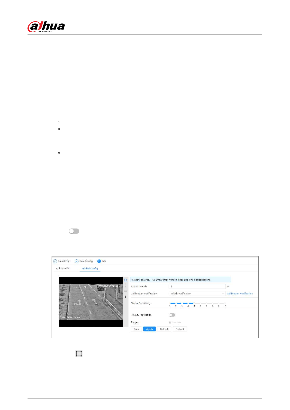
3. Click the Global Cong tab.
Figure 8-21 Global conguration of IVS
4. Set calibration area and ruler.
a. Click
and draw a calibration area in the image, and right-click to nish the drawing.
b. Click the ruler icon to draw one horizontal ruler and three vertical rulers in the calibration
area.
Operation Manual
132
Loading ...
Loading ...
Loading ...