
02/12 0068660
INSTRUCTION MANUAL
GUIDE D'UTILISATION
MANUAL DE INSTRUCCIONES
If you have questions or comments, contact us.
Pour toute question ou tout commentaire, nous contacter.
Si tiene dudas o comentarios, contáctenos.
1-8888-4431-66871 •• wwww.dewalt.com
INSTRUCTIVO DE OPERACIÓN, CENTROS DE SERVICIO Y PÓLIZA
DE GARANTÍA. ADVERTENCIA: LÉASE ESTE INSTRUCTIVO ANTES
DE USAR EL PRODUCTO.
Generator DXGN Series
Génératrice DXGN Collection
Generador Serie de DXGN

0068660
2
English
CONTACT INFORMATION
For Parts, Service or your nearest distributor call:
U.S. and Canada
(888) 431-6871
Website:
www.dewalt.com

0068660
3
Table of Contents
ENGLISH INSTRUCTIONS . . . . . . . . . . . . . . . . . . . . . . . . . . . . . . . . . . . . . . . . . . . . . . . . . . . . . . . . . . . . . . . . . . . . . . . . . . 5
SAFETY . . . . . . . . . . . . . . . . . . . . . . . . . . . . . . . . . . . . . . . . . . . . . . . . . . . . . . . . . . . . . . . . . . . . . . . . . . . . . . . . . . . . . . . . . . . . . . . . . . . . . 5
SAFETY GUIDELINES AND DEFINITIONS . . . . . . . . . . . . . . . . . . . . . . . . . . . . . . . . . . . . . . . . . . . . . . . . . . . . . . . . . . . . . . . . . . . . . 5
SAFETY RULES . . . . . . . . . . . . . . . . . . . . . . . . . . . . . . . . . . . . . . . . . . . . . . . . . . . . . . . . . . . . . . . . . . . . . . . . . . . . . . . . . . . . . . . . . . . . 5
LIFTING HOOK ASSEMBLY . . . . . . . . . . . . . . . . . . . . . . . . . . . . . . . . . . . . . . . . . . . . . . . . . . . . . . . . . . . . . . . . . . . . . . . . . . . . . . . . . . . 7
RAISING OR SUSPENDING GENERATOR. . . . . . . . . . . . . . . . . . . . . . . . . . . . . . . . . . . . . . . . . . . . . . . . . . . . . . . . . . . . . . . . . . . . . . . . 7
Limited warranty . . . . . . . . . . . . . . . . . . . . . . . . . . . . . . . . . . . . . . . . . . . . . . . . . . . . . . . . . . . . . . . . . . . . . . . . . . . . . . . . . . . . . . . . . . . . . . 8
FEDERAL EVAPORATIVE EMISSION CONTROL WARRANTY. . . . . . . . . . . . . . . . . . . . . . . . . . . . . . . . . . . . . . . . . . . . . . . . . . . . . . 9
EVAPORATIVE EMISSION CONTROL SYSTEM. . . . . . . . . . . . . . . . . . . . . . . . . . . . . . . . . . . . . . . . . . . . . . . . . . . . . . . . . . . . . . . . . . 10
CALIFORNIA EMISSION CONTROL WARRANTY. . . . . . . . . . . . . . . . . . . . . . . . . . . . . . . . . . . . . . . . . . . . . . . . . . . . . . . . . . . . . . . . 11
OPERATION . . . . . . . . . . . . . . . . . . . . . . . . . . . . . . . . . . . . . . . . . . . . . . . . . . . . . . . . . . . . . . . . . . . . . . . . . . . . . . . . . . . . . . . . . . . . . . . . 12
GENERAL INFORMATION . . . . . . . . . . . . . . . . . . . . . . . . . . . . . . . . . . . . . . . . . . . . . . . . . . . . . . . . . . . . . . . . . . . . . . . . . . . . . . . . . . 12
BEFORE START-UP . . . . . . . . . . . . . . . . . . . . . . . . . . . . . . . . . . . . . . . . . . . . . . . . . . . . . . . . . . . . . . . . . . . . . . . . . . . . . . . . . . . . . . . . 12
OPERATION . . . . . . . . . . . . . . . . . . . . . . . . . . . . . . . . . . . . . . . . . . . . . . . . . . . . . . . . . . . . . . . . . . . . . . . . . . . . . . . . . . . . . . . . . . . . . . 12
GENERATOR APPLICATION . . . . . . . . . . . . . . . . . . . . . . . . . . . . . . . . . . . . . . . . . . . . . . . . . . . . . . . . . . . . . . . . . . . . . . . . . . . . . . . . 14
LOADING YOUR GENERATOR SET. . . . . . . . . . . . . . . . . . . . . . . . . . . . . . . . . . . . . . . . . . . . . . . . . . . . . . . . . . . . . . . . . . . . . . . . . . 14
RECEPTACLE DETAILS . . . . . . . . . . . . . . . . . . . . . . . . . . . . . . . . . . . . . . . . . . . . . . . . . . . . . . . . . . . . . . . . . . . . . . . . . . . . . . . . . . . . 14
ENGINE LIMITATIONS ON GENERATOR PERFORMANCE . . . . . . . . . . . . . . . . . . . . . . . . . . . . . . . . . . . . . . . . . . . . . . . . . . . . . . 14
GENERATOR CLEANING . . . . . . . . . . . . . . . . . . . . . . . . . . . . . . . . . . . . . . . . . . . . . . . . . . . . . . . . . . . . . . . . . . . . . . . . . . . . . . . . . . . 14
GENERAL STORAGE GUIDELINES . . . . . . . . . . . . . . . . . . . . . . . . . . . . . . . . . . . . . . . . . . . . . . . . . . . . . . . . . . . . . . . . . . . . . . . . . . 15
GENERAL MAINTENANCE . . . . . . . . . . . . . . . . . . . . . . . . . . . . . . . . . . . . . . . . . . . . . . . . . . . . . . . . . . . . . . . . . . . . . . . . . . . . . . . . . . . 15
Engine Specifications and Capacities. . . . . . . . . . . . . . . . . . . . . . . . . . . . . . . . . . . . . . . . . . . . . . . . . . . . . . . . . . . . . . . . . . . . . . . . . . . . 15
Oil Selection . . . . . . . . . . . . . . . . . . . . . . . . . . . . . . . . . . . . . . . . . . . . . . . . . . . . . . . . . . . . . . . . . . . . . . . . . . . . . . . . . . . . . . . . . . . . . . . 16
Engine Maintenance Schedule . . . . . . . . . . . . . . . . . . . . . . . . . . . . . . . . . . . . . . . . . . . . . . . . . . . . . . . . . . . . . . . . . . . . . . . . . . . . . . . . . 16
DAILY INSPECTION . . . . . . . . . . . . . . . . . . . . . . . . . . . . . . . . . . . . . . . . . . . . . . . . . . . . . . . . . . . . . . . . . . . . . . . . . . . . . . . . . . . . . . . 16
SPARK ARRESTER. . . . . . . . . . . . . . . . . . . . . . . . . . . . . . . . . . . . . . . . . . . . . . . . . . . . . . . . . . . . . . . . . . . . . . . . . . . . . . . . . . . . . . . . . 17
FAULT FINDING GUIDE . . . . . . . . . . . . . . . . . . . . . . . . . . . . . . . . . . . . . . . . . . . . . . . . . . . . . . . . . . . . . . . . . . . . . . . . . . . . . . . . . . . . 17
FRENCH INSTRUCTIONS . . . . . . . . . . . . . . . . . . . . . . . . . . . . . . . . . . . . . . . . . . . . . . . . . . . . . . . . . . . . . . . . . . . . . . . . . . 18
SÉCURITÉ . . . . . . . . . . . . . . . . . . . . . . . . . . . . . . . . . . . . . . . . . . . . . . . . . . . . . . . . . . . . . . . . . . . . . . . . . . . . . . . . . . . . . . . . . . . . . . . . . . 18
DIRECTIVES EN MATIÈRE DE SÉCURITÉ ET DÉFINITIONS . . . . . . . . . . . . . . . . . . . . . . . . . . . . . . . . . . . . . . . . . . . . . . . . . . . . 18
règles de sécurité. . . . . . . . . . . . . . . . . . . . . . . . . . . . . . . . . . . . . . . . . . . . . . . . . . . . . . . . . . . . . . . . . . . . . . . . . . . . . . . . . . . . . . . . . . . . 18
ASSEMBLAGE DE LA BARRE DE LEVAGE . . . . . . . . . . . . . . . . . . . . . . . . . . . . . . . . . . . . . . . . . . . . . . . . . . . . . . . . . . . . . . . . . . . . . 20
SOULEVER OU SUSPENDRE LE GÉNÉRATEUR . . . . . . . . . . . . . . . . . . . . . . . . . . . . . . . . . . . . . . . . . . . . . . . . . . . . . . . . . . . . . . . . . 20
GARANTIE LIMITÉE. . . . . . . . . . . . . . . . . . . . . . . . . . . . . . . . . . . . . . . . . . . . . . . . . . . . . . . . . . . . . . . . . . . . . . . . . . . . . . . . . . . . . . . . . 21
UTILISATION . . . . . . . . . . . . . . . . . . . . . . . . . . . . . . . . . . . . . . . . . . . . . . . . . . . . . . . . . . . . . . . . . . . . . . . . . . . . . . . . . . . . . . . . . . . . . . . 22
INFORMATION GÉNÉRALE. . . . . . . . . . . . . . . . . . . . . . . . . . . . . . . . . . . . . . . . . . . . . . . . . . . . . . . . . . . . . . . . . . . . . . . . . . . . . . . . . 22
AVANT LE DÉMARRAGE . . . . . . . . . . . . . . . . . . . . . . . . . . . . . . . . . . . . . . . . . . . . . . . . . . . . . . . . . . . . . . . . . . . . . . . . . . . . . . . . . . . 22
UTILISATION . . . . . . . . . . . . . . . . . . . . . . . . . . . . . . . . . . . . . . . . . . . . . . . . . . . . . . . . . . . . . . . . . . . . . . . . . . . . . . . . . . . . . . . . . . . . . 22
USAGE DE LA GÉNÉRATRICE . . . . . . . . . . . . . . . . . . . . . . . . . . . . . . . . . . . . . . . . . . . . . . . . . . . . . . . . . . . . . . . . . . . . . . . . . . . . . . 24
charger votre génératrice . . . . . . . . . . . . . . . . . . . . . . . . . . . . . . . . . . . . . . . . . . . . . . . . . . . . . . . . . . . . . . . . . . . . . . . . . . . . . . . . . . . . . 24
Détails des réceptacles (prise femelle) . . . . . . . . . . . . . . . . . . . . . . . . . . . . . . . . . . . . . . . . . . . . . . . . . . . . . . . . . . . . . . . . . . . . . . . . . . . 24
Limite du moteur sur la performance de la génératrice . . . . . . . . . . . . . . . . . . . . . . . . . . . . . . . . . . . . . . . . . . . . . . . . . . . . . . . . . . . . . . 24
Nettoyage de la génératrice . . . . . . . . . . . . . . . . . . . . . . . . . . . . . . . . . . . . . . . . . . . . . . . . . . . . . . . . . . . . . . . . . . . . . . . . . . . . . . . . . . . 24
Règles générales d'entretien . . . . . . . . . . . . . . . . . . . . . . . . . . . . . . . . . . . . . . . . . . . . . . . . . . . . . . . . . . . . . . . . . . . . . . . . . . . . . . . . . . . 25
ENTRETIEN GÉNÉRAL. . . . . . . . . . . . . . . . . . . . . . . . . . . . . . . . . . . . . . . . . . . . . . . . . . . . . . . . . . . . . . . . . . . . . . . . . . . . . . . . . . . . . . . 25
spécifications du moteur et capacités . . . . . . . . . . . . . . . . . . . . . . . . . . . . . . . . . . . . . . . . . . . . . . . . . . . . . . . . . . . . . . . . . . . . . . . . . . . . 26
Sélection d'huile . . . . . . . . . . . . . . . . . . . . . . . . . . . . . . . . . . . . . . . . . . . . . . . . . . . . . . . . . . . . . . . . . . . . . . . . . . . . . . . . . . . . . . . . . . . . 26
horaire d'entretien du moteur . . . . . . . . . . . . . . . . . . . . . . . . . . . . . . . . . . . . . . . . . . . . . . . . . . . . . . . . . . . . . . . . . . . . . . . . . . . . . . . . . . 27
INSPECTION quotidienne . . . . . . . . . . . . . . . . . . . . . . . . . . . . . . . . . . . . . . . . . . . . . . . . . . . . . . . . . . . . . . . . . . . . . . . . . . . . . . . . . . . . 27
PARE-ÉTINCELLES . . . . . . . . . . . . . . . . . . . . . . . . . . . . . . . . . . . . . . . . . . . . . . . . . . . . . . . . . . . . . . . . . . . . . . . . . . . . . . . . . . . . . . . . 27
guide des failles . . . . . . . . . . . . . . . . . . . . . . . . . . . . . . . . . . . . . . . . . . . . . . . . . . . . . . . . . . . . . . . . . . . . . . . . . . . . . . . . . . . . . . . . . . . . 28

4
0068660
SPANISH INSTRUCTIONS . . . . . . . . . . . . . . . . . . . . . . . . . . . . . . . . . . . . . . . . . . . . . . . . . . . . . . . . . . . . . . . . . . . . . . . . . . 29
SEGURIDAD . . . . . . . . . . . . . . . . . . . . . . . . . . . . . . . . . . . . . . . . . . . . . . . . . . . . . . . . . . . . . . . . . . . . . . . . . . . . . . . . . . . . . . . . . . . . . . . . . . 29
LINEAMIENTOS DE SEGURIDAD Y DEFINICIONES . . . . . . . . . . . . . . . . . . . . . . . . . . . . . . . . . . . . . . . . . . . . . . . . . . . . . . . . . . . 29
reglas de seguridad . . . . . . . . . . . . . . . . . . . . . . . . . . . . . . . . . . . . . . . . . . . . . . . . . . . . . . . . . . . . . . . . . . . . . . . . . . . . . . . . . . . . . . . . . . 29
ENSAMBLAJE DEL GANCHO PARA LEVANTAR . . . . . . . . . . . . . . . . . . . . . . . . . . . . . . . . . . . . . . . . . . . . . . . . . . . . . . . . . . . . . . . . 31
ELEVACIÓN O SUSPENSIÓN DEL GENERADOR . . . . . . . . . . . . . . . . . . . . . . . . . . . . . . . . . . . . . . . . . . . . . . . . . . . . . . . . . . . . . . . . 31
GARANTIA LIMITADA . . . . . . . . . . . . . . . . . . . . . . . . . . . . . . . . . . . . . . . . . . . . . . . . . . . . . . . . . . . . . . . . . . . . . . . . . . . . . . . . . . . . . . . 32
FUNCIONAMIENTO . . . . . . . . . . . . . . . . . . . . . . . . . . . . . . . . . . . . . . . . . . . . . . . . . . . . . . . . . . . . . . . . . . . . . . . . . . . . . . . . . . . . . . . . . 33
INFORMACIÓN GENERAL. . . . . . . . . . . . . . . . . . . . . . . . . . . . . . . . . . . . . . . . . . . . . . . . . . . . . . . . . . . . . . . . . . . . . . . . . . . . . . . . . . 33
comenzando . . . . . . . . . . . . . . . . . . . . . . . . . . . . . . . . . . . . . . . . . . . . . . . . . . . . . . . . . . . . . . . . . . . . . . . . . . . . . . . . . . . . . . . . . . . . . . . 33
funcionamiento . . . . . . . . . . . . . . . . . . . . . . . . . . . . . . . . . . . . . . . . . . . . . . . . . . . . . . . . . . . . . . . . . . . . . . . . . . . . . . . . . . . . . . . . . . . . . 33
APLICACIÓN del generador . . . . . . . . . . . . . . . . . . . . . . . . . . . . . . . . . . . . . . . . . . . . . . . . . . . . . . . . . . . . . . . . . . . . . . . . . . . . . . . . . . 35
Carga DE su generador. . . . . . . . . . . . . . . . . . . . . . . . . . . . . . . . . . . . . . . . . . . . . . . . . . . . . . . . . . . . . . . . . . . . . . . . . . . . . . . . . . . . . . . 35
detalles de receptaculos . . . . . . . . . . . . . . . . . . . . . . . . . . . . . . . . . . . . . . . . . . . . . . . . . . . . . . . . . . . . . . . . . . . . . . . . . . . . . . . . . . . . . . 35
limitaciones del motor y rendimiento del generador . . . . . . . . . . . . . . . . . . . . . . . . . . . . . . . . . . . . . . . . . . . . . . . . . . . . . . . . . . . . . . . . 35
limpieza del generador . . . . . . . . . . . . . . . . . . . . . . . . . . . . . . . . . . . . . . . . . . . . . . . . . . . . . . . . . . . . . . . . . . . . . . . . . . . . . . . . . . . . . . . 35
almacenamiento general pautas . . . . . . . . . . . . . . . . . . . . . . . . . . . . . . . . . . . . . . . . . . . . . . . . . . . . . . . . . . . . . . . . . . . . . . . . . . . . . . . . 36
MANTENIMIENTO GENERAL. . . . . . . . . . . . . . . . . . . . . . . . . . . . . . . . . . . . . . . . . . . . . . . . . . . . . . . . . . . . . . . . . . . . . . . . . . . . . . . . . 36
especificaciones y capacidades del motor . . . . . . . . . . . . . . . . . . . . . . . . . . . . . . . . . . . . . . . . . . . . . . . . . . . . . . . . . . . . . . . . . . . . . . . . 37
Selection de aceite . . . . . . . . . . . . . . . . . . . . . . . . . . . . . . . . . . . . . . . . . . . . . . . . . . . . . . . . . . . . . . . . . . . . . . . . . . . . . . . . . . . . . . . . . . 37
programa de mantenimiento de motor . . . . . . . . . . . . . . . . . . . . . . . . . . . . . . . . . . . . . . . . . . . . . . . . . . . . . . . . . . . . . . . . . . . . . . . . . . . 38
inspeccion diaria . . . . . . . . . . . . . . . . . . . . . . . . . . . . . . . . . . . . . . . . . . . . . . . . . . . . . . . . . . . . . . . . . . . . . . . . . . . . . . . . . . . . . . . . . . . . 38
PARACHISPAS . . . . . . . . . . . . . . . . . . . . . . . . . . . . . . . . . . . . . . . . . . . . . . . . . . . . . . . . . . . . . . . . . . . . . . . . . . . . . . . . . . . . . . . . . . . . 38
Guia para encontrar fallas. . . . . . . . . . . . . . . . . . . . . . . . . . . . . . . . . . . . . . . . . . . . . . . . . . . . . . . . . . . . . . . . . . . . . . . . . . . . . . . . . . . . . 39
All information provided in this manual is believed to be correct at the time of printing. The manufacturer reserves the right to
correct any errors and omissions.
0068660
5
English
SAFETY GUIDELINES AND DEFINITIONS
This instruction manual contains information important for you
to know and understand so that your generator may properly,
safely, and effectively applied and operated. All operators,
users and subsequent owners of this generator must read and
understand all instructions before operating the generator.
Save these instructions for future reference.
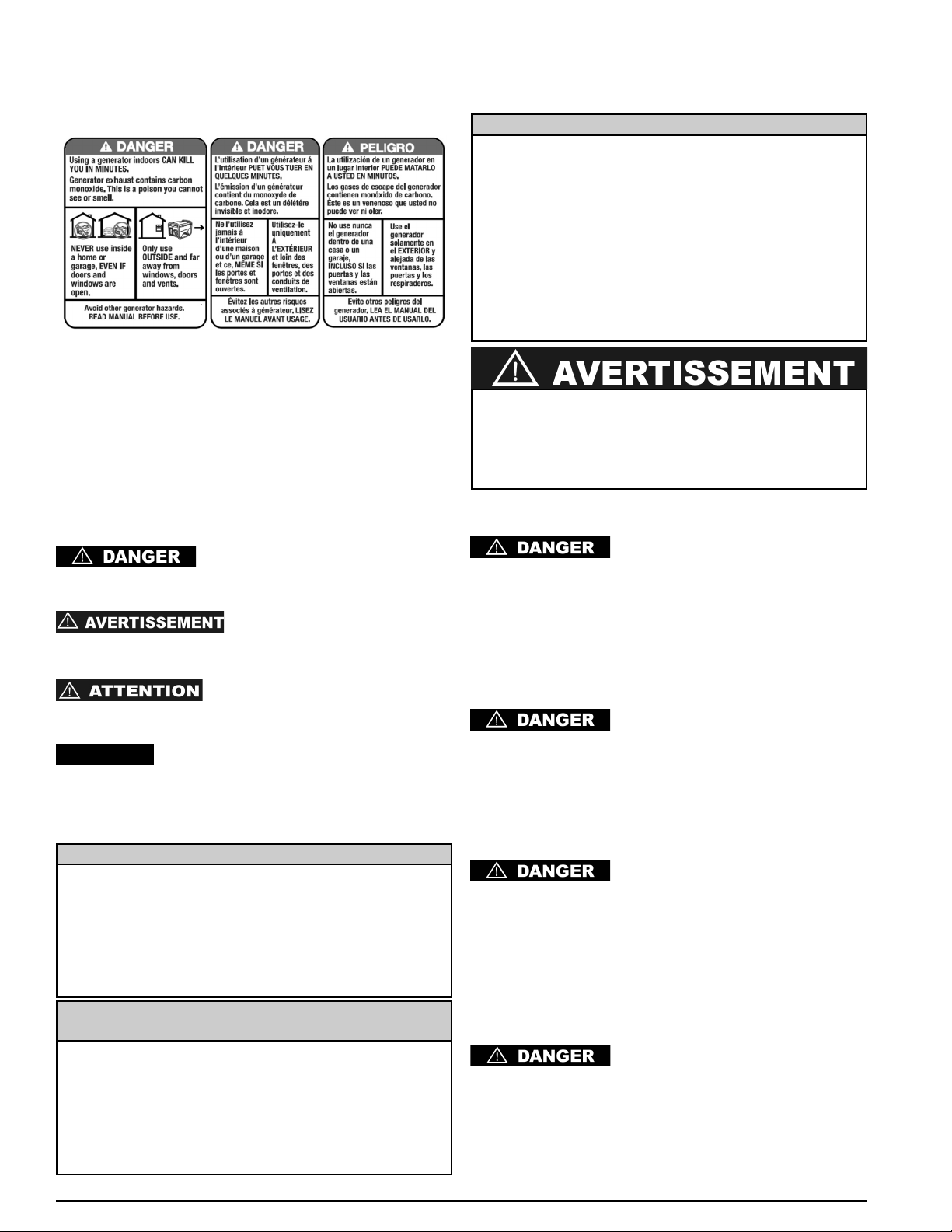
To help you recognize information important to protecting
YOUR SAFETY and PREVENTING EQUIPMENT PROBLEMS,
we use the symbols below.
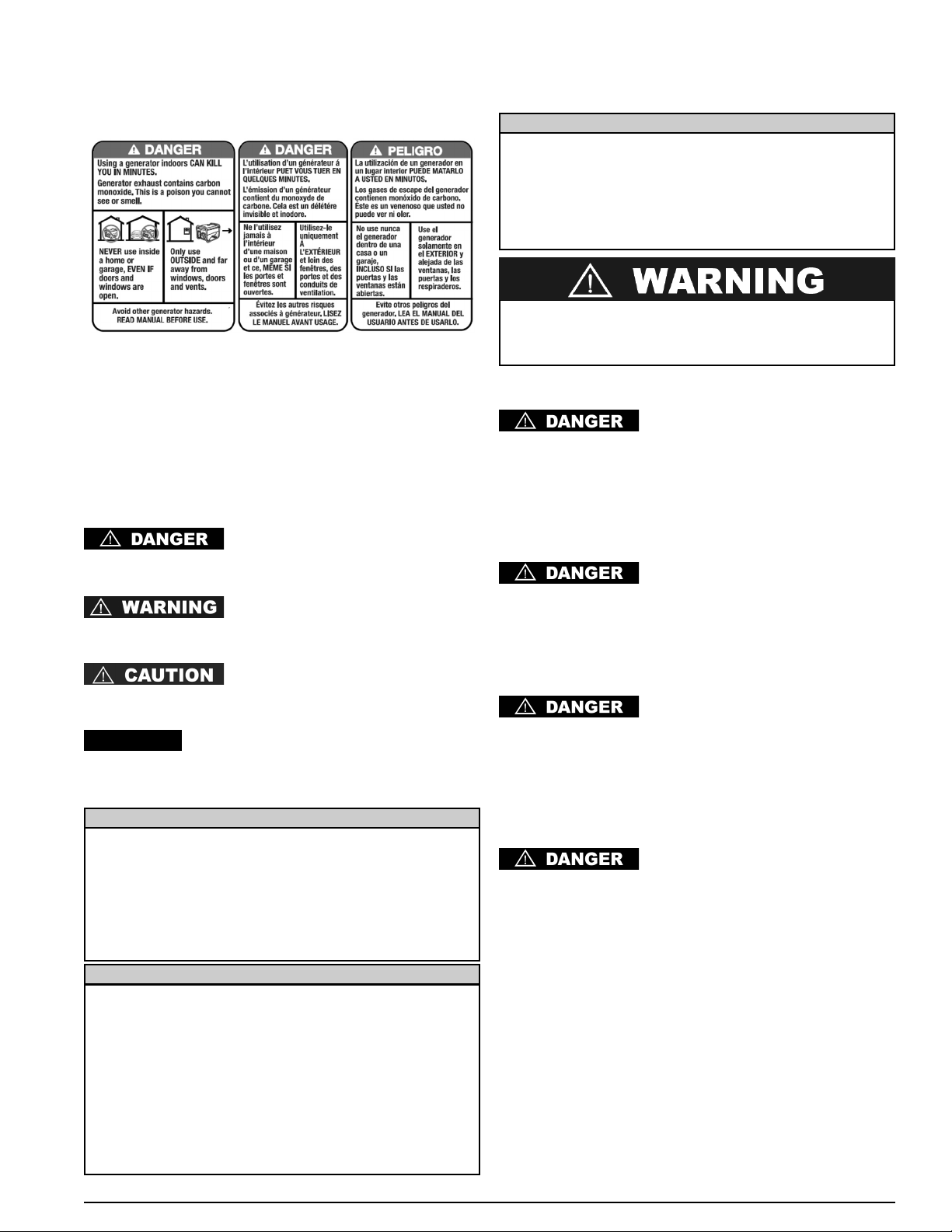
Indicates and imminently hazardous
situation which, if not avoided, will result in death or serious
injury.
Indicates a potentially hazardous
situation which, if not avoided, could result in death or serious
injury.
Indicates a potentially hazardous
situation which, if not avoided, may result in minor or moderate
injury.
Indicates a practice not related to personal
injury which, if not avoided, may result in property damage.
SAFETY RULES
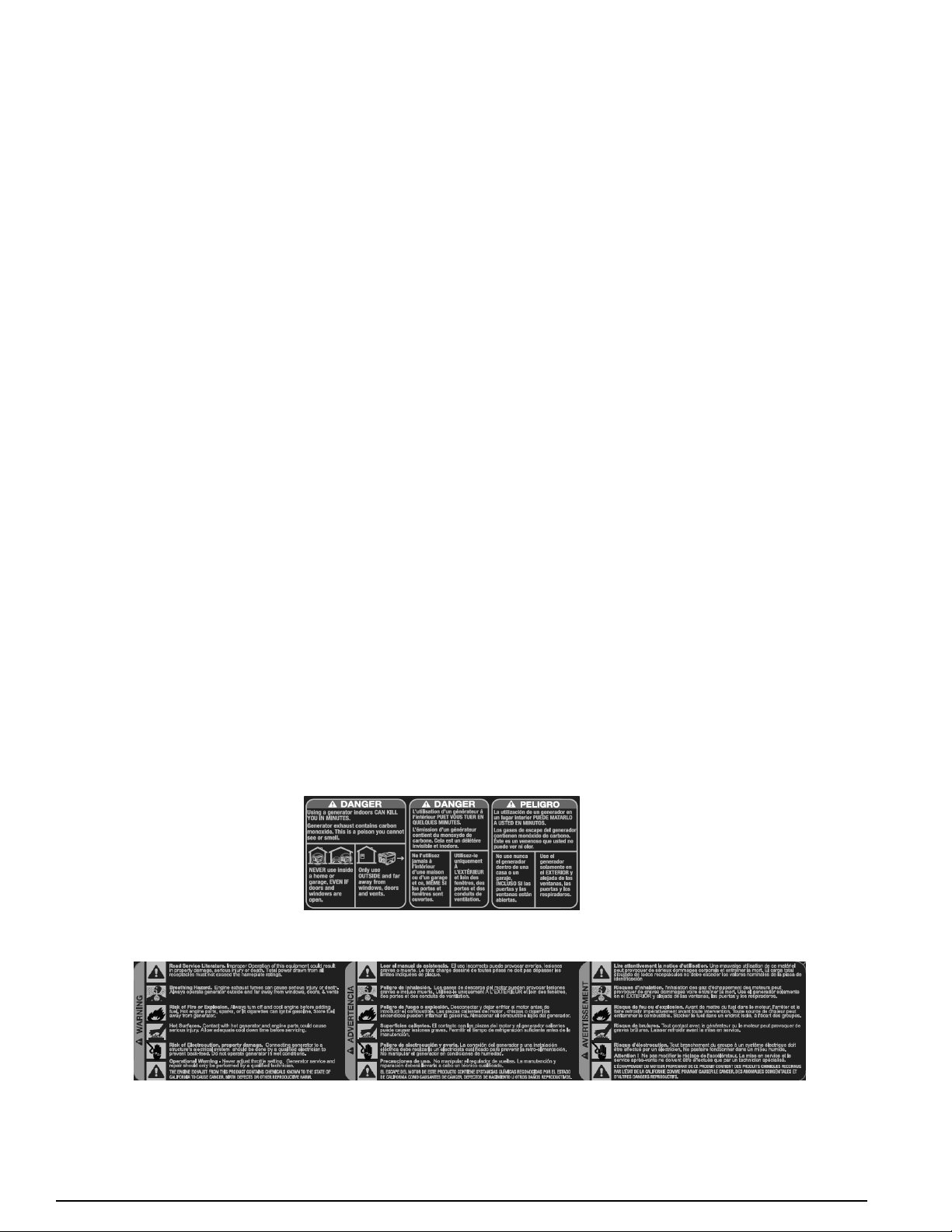
RISK OF ASPHYXIATION
DO NOT OPERATE THIS
GENERATOR WITHIN AN ENCLOSED AREA. THE EXHAUST
GASES OF THIS GENERATOR EMIT “DEADLY” CARBON
MONOXIDE. EXPOSURE TO CARBON MONOXIDE CAN
CAUSE CARBON MONOXIDE POISONING, HEADACHES,
NAUSEA, SEVERE SICKNESS OR DEATH.
RISK OF ELECTROCUTION OR SHOCK
THIS GENERATOR SET PRODUCES
ELECTRICAL CURRENT. THEREFORE, SAFETY
GUIDELINES MUST BE FOLLOWED. IMPROPER USE OF
THIS GENERATOR CAN RESULT IN ELECTROCUTION,
INJURY OR DEATH. DO NOT OPERATE, SERVICE OR
REPAIR THIS GENERATOR UNLESS FULLY QUALIFIED TO
DO SO.
THIS GENERATOR SET IS
DESIGNED TO BE OPERATED IN DRY CONDITIONS AND
FOR OUTDOOR AREAS ONLY. NEVER OPERATE THIS
GENERATOR INDOORS. NEVER OPERATE THIS
GENERATOR IN RAIN, SNOW, SLEET OR GENERALLY WET
CONDITIONS. DAMAGE TO THE GENERATOR, BODILY
INJURY, OR DEATH COULD RESULT FROM
ELECTROCUTION.
IF THIS GENERATOR IS CONNECTED
TO A BUILDING, HOME, BUSINESS, OR ANY OTHER
ELECTRICAL CIRCUIT NORMALLY FED BY UTILITY
POWER, STEPS MUST BE TAKEN TO INSURE THE
GENERATOR OUTPUT AND THE UTILITY POWER ARE
POSITIVELY ISOLATED. THIS IS TYPICALLY
ACCOMPLISHED THROUGH THE USE OF A PROPERLY
INSTALLED TRANSFER SWITCH. FAILURE TO ISOLATE
THE UTILITY AND GENERATOR ELECTRICAL SYSTEMS
WILL RESULT IN GENERATOR DAMAGE AND COULD
RESULT IN INJURY OR DEATH TO UTILITY WORKERS DUE
TO THE BACKFEED OF ELECTRICITY.
ENGLISH INSTRUCTIONS
SAFETY
Certain States and Jurisdictions require that engine driven
equipment be fitted with spark arresting mufflers. Depending
on the generator model, spark-arresting mufflers may or
may not be fitted. If spark-arresting mufflers are required for
your location and the generator muffler is not spark
arresting, contact your local dealer for instructions for a
retrofit.
SPARK ARRESTING MUFFLER
The exhaust emission control system for this generator
complies with the standards set forth by the California Air
Resources Board (CARB) and the Environmental Protection
Agency (EPA). The respective engine manufacturers
administer warranties for the exhaust emission system.
Refer to the engine documentation for warranty information.
EXHAUST EMISSION CONTROL SYSTEM
The engine exhaust from this product contains
chemicals known to the State of California to cause
cancer, birth defects, or other reproductive harm.
If the product will be used around flammable materials, such as
agricultural crops, forests, brush, grass, or other similar items,
then an approved spark arrester should be installed and is
legally required in the State of California. The California
statutes requiring a spark arrester are Sections 13005(b), 4442
and 4443. Spark Arresters are also required on some U.S.
Forest Service land and may also be legally required under
other statutes and ordinances. An approved spark arrester is
available from our product dealers, or may be ordered from
D
EWALT Industrial Tool Co., 701 East Joppa Road, Baltimore,
MD 21286. 1-888-431-6871.
SPARK ARRESTER
NOTICE:
TO AVOID BACKFEEDING INTO
UTILITY SYSTEMS, ISOLATION OF THE RESIDENCE
ELECTRICAL SYSTEM IS REQUIRED. BEFORE
CONNECTION OF A GENERATOR TO THE RESIDENCE
ELECTRICAL SYSTEM TURN OFF THE MAIN SWITCH.
BEFORE MAKING PERMANENT CONNECTIONS A DOUBLE
THROW TRANSFER SWITCH MUST BE INSTALLED. TO
AVOID ELECTROCUTION OR PROPERTY DAMAGE, ONLY
A TRAINED ELECTRICIAN SHOULD CONNECT
GENERATOR TO RESIDENCE ELECTRICAL SYSTEM.
CALIFORNIA LAW REQUIRES ISOLATION OF THE
RESIDENCE ELECTRICAL SYSTEM BEFORE CONNECTING
A GENERATOR TO RESIDENCE ELECTRICAL SYSTEMS.
TEMPORARY CONNECTION NOT RECOMMENDED DUE TO
BACKFEEDING.
ALWAYS FOLLOW LOCAL CODES AND REGULATIONS
THAT APPLY TO THE INSTALLATION OF ANY ITEM THAT
CONCERNS THIS PRODUCT.
1. NFPA 70 - National Electrical Code.
2. NFPA 37 - Standard for Installation and Use of
Stationary Combustible Engines.
3. Agricultural Wiring handbook of Farm Standby
Electric Power.
DO NOT MODIFY OR MISAPPLY
YOUR GENERATOR SET. OPERATION OF THE
GENERATOR OTHER THAN INTENDED COULD RESULT IN
GENERATOR SET DAMAGE, BODILY INJURY OR EVEN
DEATH FROM ELECTROCUTION.
NEVER TOUCH A RECEPTACLE OR
BARE WIRE. ELECTROCUTION OR SHOCK COULD
RESULT.
RISK OF FIRE OR EXPLOSION
ALWAYS INSURE THAT AT LEAST 6
FEET OF CLEARANCE ON ALL SIDES OF THE
GENERATOR ARE MAINTAINED DURING OPERATION.
FAILURE TO MAINTAIN PROPER CLEARANCE COULD
DAMAGE YOUR GENERATOR AND POTENTIALLY LEAD TO
FIRES.
GASOLINE IS HIGHLY FLAMMABLE
AND ITS VAPORS ARE EXPLOSIVE. FAILURE TO
PROPERLY HANDLE GASOLINE CAN RESULT IN
EXPLOSION OR FIRE. DO NOT PERMIT SMOKING WITHIN
50FT OF THIS GENERATOR SET.
NEVER REFILL A HOT GENERATOR
WITH FUEL. NEVER REFILL THE GENERATOR WHILE IT IS
RUNNING. SPILLAGE ONTO THE ENGINE OR GENERATOR
COULD RESULT IN AN EXPLOSION OR FIRE. ALWAYS
ALLOW THE GENERATOR SET TO COOL BEFORE
REFILLING.
DO NOT STORE THIS GENERATOR
SET IN ANY LOCATION WHERE GASOLINE FUMES COULD
POTENTIALLY COME INTO CONTACT WITH SPARKS, A
PILOT LIGHT OR AN OPEN FLAME. IMPROPER STORAGE
OF THIS GENERATOR COULD RESULT IN AN EXPLOSION
OR FIRE.
INSPECT THE SPARK ARRESTOR
PERIODICALLY. SPARK ARRESTORS ARE REQUIRED IN
SOME AREAS AND MINIMIZE THE RISK OF FIRE FROM
SPARKS EMMITTED FROM THE EXHAUST.
DO NOT OPERATE THIS
GENERATOR IF THE AMBIENT TEMPERATURE EXCEEDS
104ºF/40ºC.
DO NOT EXCEED THE RATED
CAPACITY OF THE GENERATOR. THE TOTAL ELECTRICAL
LOADS AT EACH OUTLET MUST BE ADDED TO
DETERMINE THE TOTAL ELECTRICAL LOAD. THE TOTAL
LOAD MUST NOT EXCEED THE RATED CAPACITY OF THE
GENERATOR. IF THE DRIVEN APPARATUS DOES NOT LIST
WATTAGE, BUT ONLY AMPERAGE, WATTAGE MAY BE
DETERMINED BY MULTIPLYING AMPERAGE TIMES
VOLTAGE (WATTS = AMPS X VOLTS).
GENERAL SAFETY
Always follow National and Local electrical codes pertaining to
generators. All local and national codes supersede rules or
information provided in this manual.
REFER TO LOCAL AND NATIONAL
ELECTRICAL CODES TO DETERMINE GROUNDING
REQUIREMENTS AS THIS CAN VARY PER APPLICATION.
THE GENERATOR IS GROUNDED INTERNALLY NEUTRAL
TO FRAME. WHERE APPLICATIONS REQUIRE EXTERNAL
GROUNDING, A CONNECTION MUST BE MADE FROM THE
GENERATOR TO A SOLID EARTH GROUND. A
CONTINUOUS LENGTH OF SPLICE-FREE COPPER CABLE,
NO SMALLER THAN 6 AWG, SHALL BE USED FOR THE
CONDUCTOR.
• When moving or transporting this generator, take proper
precautions to avoid fuel spillage. Further, always use
common sense when lifting this generator. An adequate
number of people and proper lifting methods must be
used.
• Do not cover the generator while it is running or
immediately after shutdown. Always allow time to cool
down before covering.
• Do not operate this generator unless it is in good
mechanical and electrical condition.
• Always keep hands, body parts, hair and clothing well
away from the rotating parts of the generator.
• Do not start this generator with connected devices turned
“ON”. Always make sure that connected devices are
disconnected from the generator or turned “OFF” before
starting the generator.
• Generators operating on job or construction sites may be
required to have GFCI (Ground Fault Circuit Interrupters)
receptacles.
• Use only grounded extension cords in good condition and
make sure that the wire size within the extension cords is
of sufficient size to safely carry the surge output of the
generator.
• Never handle extension cords or electrical circuits if
standing in water or if standing in a damp area.
6
0068660English
0068660
7
English
RISK OF BODILY INJURY
KEEP HANDS, BODY PARTS, HAIR
AND CLOTHING AWAY FROM THE “HOT” PARTS OF THE
GENERATOR SET DURING AND AFTER OPERATION. THE
EXHAUST SYSTEM, AND THE GENERATOR IN GENERAL,
CAN REMAIN VERY HOT EVEN AFTER BEING SHUT
DOWN.
DO NOT TAMPER WITH THE
ENGINE-GOVERNED SPEED. THE GENERATOR
OPERATES AT A NOMINAL SPEED OF 3600 RPM.
INCREASES IN SPEED OVER THE 3600 RPM NOMINAL
WILL INCREASE THE CHANCE OF PERSONAL INJURY
DUE TO ROTATIONAL STRESSES ON THE ROTATING
MEMBERS. OPERATION OF THE GENERATOR AT SPEEDS
BELOW THE NOMINAL 3600 RPM COULD CAUSE DAMAGE
TO THE GENERATOR OR DRIVEN APPARATUS DUE TO
LOW VOLTAGE OUTPUT.
BATTERY SAFETY
STORAGE BATTERIES PRODUCE
AND RELEASE EXPLOSIVE HYDROGEN GAS WHEN
CHARGING. THE SLIGHTEST SPARK, FLAME OR BURNING
ASH CAN IGNITE THESE GASES CAUSING A SERIOUS
EXPLOSION THAT COULD RESULT IN BLINDNESS OR
OTHER SERIOUS INJURIES. WEAR EYE PROTECTION,
RUBBER APRON AND RUBBER GLOVES WHEN WORKING
AROUND A BATTERY OR PERFORMING BATTERY
SERVICE. BATTERY FLUID IS AN EXTREMELY CAUSTIC
SULFURIC ACID, WHICH CAN CAUSE SEVERE BURNS.
ALWAYS DISCONNECT THE NEGATIVE (-) BATTERY CABLE
FROM THE BATTERY BEFORE PERFORMING BATTERY
SERVICE OR BEFORE PERFORMING ANY ELECTRICAL
SERVICE ON THE GENERATOR OR ENGINE.
ENVIRONMENTAL PROTECTION
INSPECT THE EXHAUST SYSTEM
REGULARLY TO ENSURE IT IS FUNCTIONING PROPERLY.
LEAKY EXHAUST SYSTEMS WILL INCREASE NOISE
LEVELS.
DIRECT THE “LOUD” SIDES OF THE
GENERATOR INTO OPEN SPACES AVOIDING
REVERBERATION FROM WALLS OR BUILDINGS THUS
AMPLIFYING THE SOUND.
NEVER DRAIN OR DISPOSE OF ENGINE
OIL INTO THE GROUND OR DOMESTIC WASTE WATER
SYSTEMS.
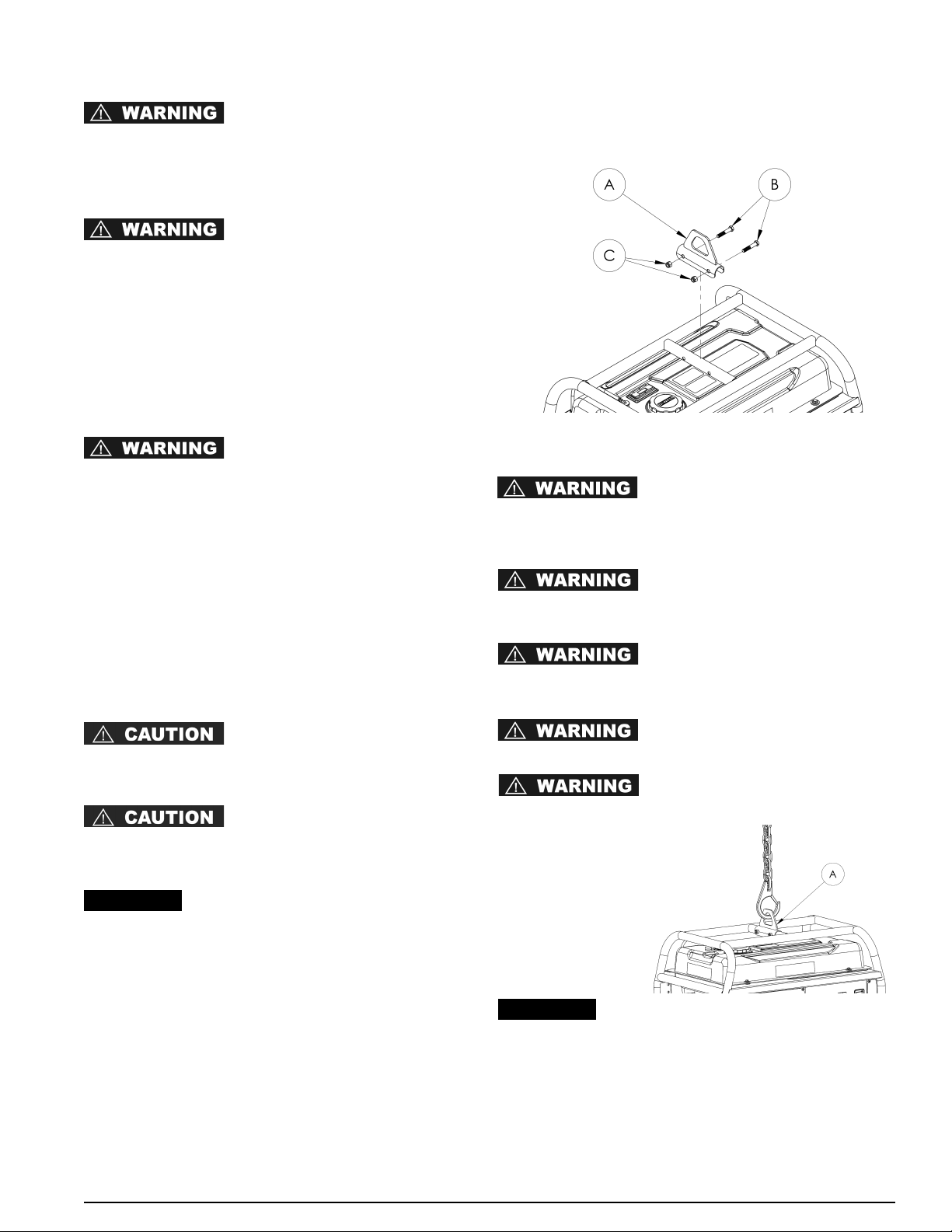
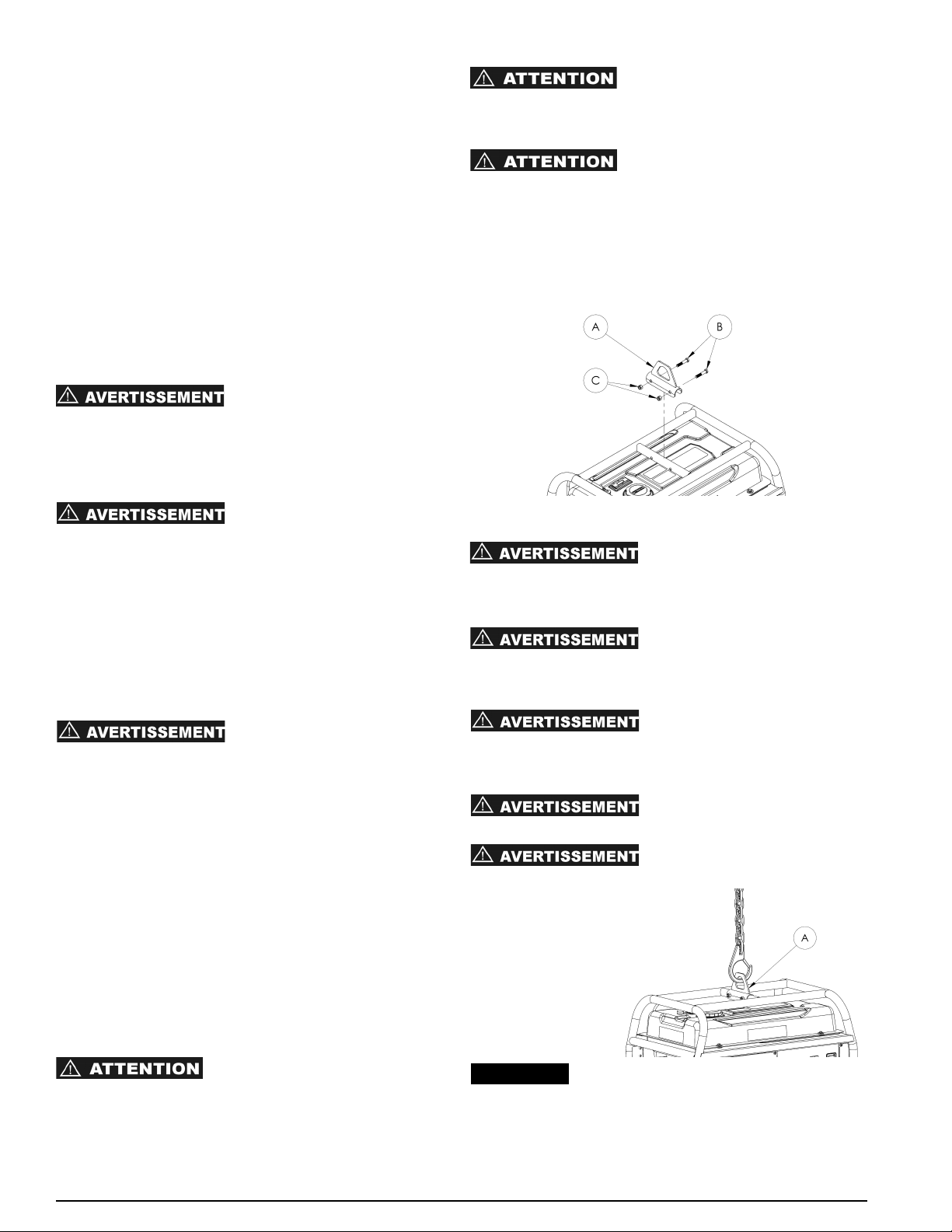
LIFTING HOOK ASSEMBLY
Attach the lifting hook (A) to the carrier with 3/8 x 2.00” bolts
(B) and 3/8 nyloc nuts (C) as shown in the illustration. Tighten
the bolts firmly.
RAISING OR SUSPENDING GENERATOR
Failure to properly connect lifting
cables, chains or straps can cause property damage,
serious injury or death, and void the manufacturer’s
warranty.
Always use cables, chains or straps
rated at 2000 lbs. working load or more to raise or
suspend generator.
Never operate generator while
suspended. This could cause property damage, serious
injury or death.
DO NOT suspend objects other
than generator from lifting hook.
Make sure all fasteners in frame
and lifting hook are tight.
Route cable, chain
or strap through
lifting hook (A) as
shown. ALWAYS
use lifting hook
when raising or
suspending
generator.
Make sure the generator is in a level
position before raising or suspending to prevent
damage.
NOTICE:
NOTICE:
8
0068660English
Accessories
Recommended accessories for use with your tool are available for purchase from your local dealer or authorized
service center. If you need assistance in locating any accessory for your tool, please contact DEWALT Industrial Tool
Co., 701 East Joppa Road, Baltimore, MD 21286, call 1-888-431-6871 or visit our website www.dewalt.com.
Service Information
Please have the following information available for all service calls:
Model Number ____________ Serial Number ___________
Date and Place of Purchase ____________________________
Repairs
To assure product SAFETY and RELIABILITY, repairs, maintenance and adjustment should be performed by a
DE
WALT factory service center, a DEWALT authorized service center or other qualified service personnel. Always
use identical replacement parts.
Three Year Warranty - U.S.A. and Canada
DEWALT heavy duty generators are warranted for three (3) years from date of purchase in the United States and
Canada. We will repair, without charge, any defects due to faulty materials or workmanship. For warranty repair
information, call 1-888-431-6871. This warranty does not apply to accessories or damage caused where repairs
have been made or attempted by others. This warranty gives you specific legal rights and you may have other rights
which vary in certain states or provinces.
One Year Warranty - Mexico
D
EWALT heavy duty generators are warranted for one (1) year from date of purchase in Mexico. We will repair,
without charge, any defects due to faulty materials or workmanship. For warranty repair information, call
1-888-431-6871. This warranty does not apply to accessories or damage caused where repairs have been made or
attempted by others. This warranty gives you specific legal rights and you may have other rights which vary in
certain states.
LATIN AMERICA (EXCEPT MEXICO): This warranty does not apply to products sold in Latin America. For products
sold in Latin America, see country specific warranty information contained either in the packaging, call the local
company or see website for warranty information.
FREE WARNING LABEL REPLACEMENT: If your warning labels become illegible or are missing, call
1-888-431-6871 for a free replacement.

9
0068660
FEDERAL EVAPORATIVE EMISSION CONTROL WARRANTY STATEMENT
YOUR WARRANTY RIGHTS AND OBLIGATIONS
The United States Environmental Protection Agency (EPA) and Pramac America, LLC (herein "Pramac America") are pleased to explain the Evaporative
Emission Control System (EECS) warranty on your 2011 model year and later generator. New equipment that uses small spark-ignited engines must be
designed, built, and equipped to meet stringent anti-smog standards for the federal government. Pramac America must warrant the evaporative emission
control system on your generator for the periods of time listed below, provided there has been no abuse, neglect or improper maintenance of your
generator.
The evaporative emission control system on this generator includes all components whose failure would increase the generator evaporative emissions of
any regulated pollutant. These components are listed in the Warranted Parts section of this warranty.
MANUFACTURER'S WARRANTY COVERAGE:
This EECS warranty is valid for three years. If, during such warranty period, any evaporative emission-related part on your equipment is found to be
defective in materials or workmanship, repairs or replacement will be performed by an authorized Pramac America warranty service center.
OWNER'S WARRANTY RESPONSIBILITIES:
As the generator owner, you are responsible for performance of the required maintenance listed in your owner's manual. Pramac America recommends that
you retain all receipts covering maintenance on your generator, but Pramac America cannot deny warranty solely for the lack of receipts. You should,
however, be aware that Pramac America may deny you warranty coverage if your generator or a part has failed due to abuse, neglect or improper
maintenance or unapproved modifications.
You are responsible for presenting your generator to an authorized Pramac America warranty service center or a distribution center as soon as the problem
exists. The warranty repairs should be completed in a reasonable amount of time, not to exceed 30 days. If you have a question regarding your warranty
coverage, you should call Pramac America Product Service at 1-800-445-1805, Email: [email protected].
DETAILS OF YOUR WARRANTY
Subject to certain conditions and exclusions as stated below, the warranty on emission-related parts is as follows:
(1) Any warranted part that is not scheduled for replacement as required maintenance in the written instructions supplied, is warranted for the EECS
period stated above. If the part fails during the period of EECS warranty coverage, the part will be repaired or replaced by Pramac America according
to Subsection (4) below. Any such part repaired or replaced under EECS warranty will be warranted for the remainder of the period.
(2) Any warranted part that is scheduled only for regular inspection in the written instructions supplied, is warranted for the EECS warranty period stated
above. Any such part repaired or replaced under EECS warranty will be warranted for the remaining warranty period.
(3) Any warranted part that is scheduled for replacement as required maintenance in the written instructions supplied, is warranted for the period of time
before the first scheduled replacement date for that part. If the part fails before the first scheduled replacement date, the part will be repaired or
replaced by Pramac America according to Subsection (4) below. Any such part repaired or replaced under EECS warranty will be warranted for the
remainder of the period prior to the first scheduled replacement date for the part.
(4) Repair or replacement of any evaporative emissions warranted part under the EECS warranty provisions herein must be performed at an authorized
Pramac America warranty service center at no charge to the owner.
(5) The generator owner will not be charged for diagnostic labor that is directly associated with diagnosis of a defective, emission-related warranted part,
provided that such diagnostic work is performed at an authorized Pramac America warranty service center.
(6) Pramac America is liable for damages to other engine or generator components proximately caused by a failure under warranty of any warranted part.
(7) Throughout the generator warranty period stated above, Pramac America will maintain a supply of warranted parts sufficient to meet the expected
demand for such parts.
(8) Any Pramac America authorized replacement parts may be used in the performance of any EECS warranty maintenance or repairs and must be
provided without charge to the owner. Such use will not reduce the EECS warranty obligations of Pramac America.
(9) No modifications, other than those explicitly approved by Pramac America, may be made to the generator. Unapproved modifications void this
EECS warranty and shall be sufficient grounds for disallowing and EECS warranty claim.
(10) Pramac America shall not be held liable hereunder for failures of any non-authorized replacement parts, or failures of any authorized parts caused by
the use of non-authorized replacement parts.
(11) Notwithstanding the provisions herein, warranty services or repairs will be provided at all of our distribution centers franchised to service the subject
engines or equipment.
WARRANTED PARTS:
The following emission warranty parts list is covered:
Fuel Tank
Fuel Cap
Fuel Hoses
Carbon Canister (if equipped)
Vapor Hoses
Hose Clamps
Hose Connectors
Vapor/Fuel Check Valve
English
10
0068660English
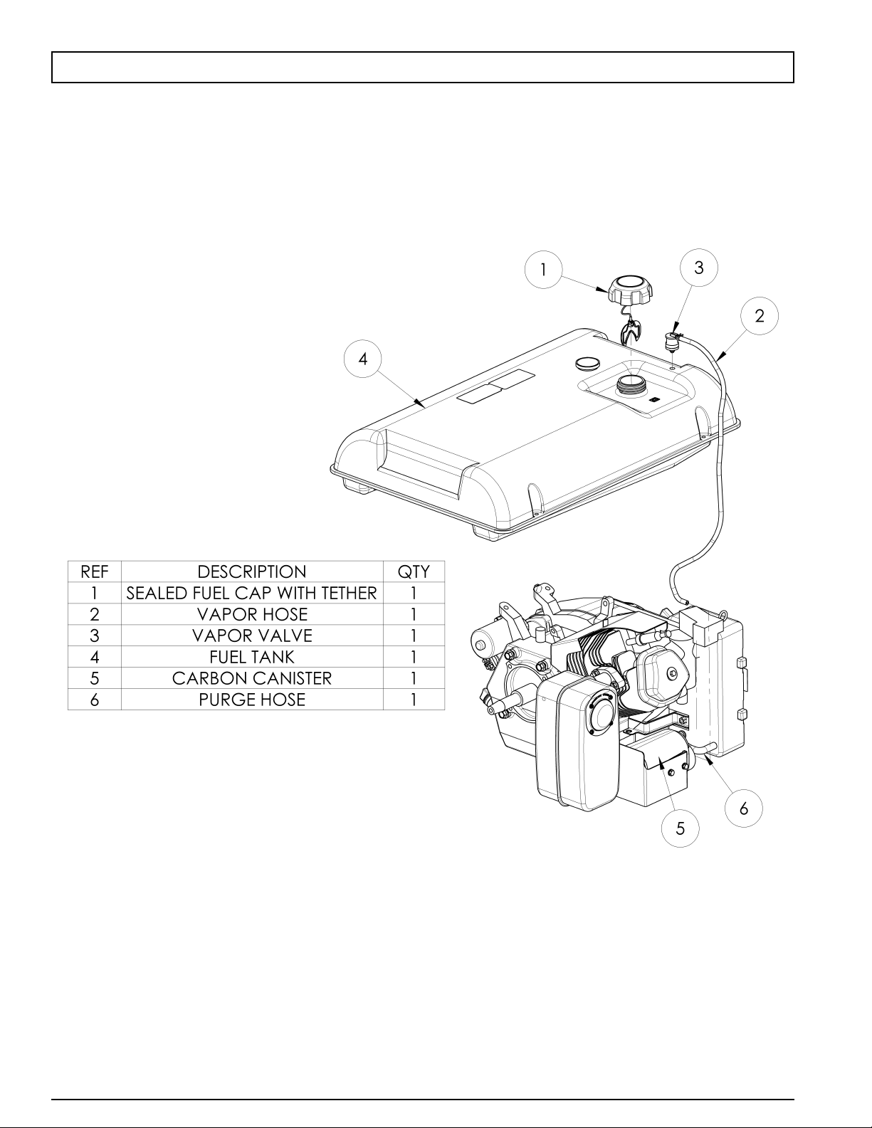
EVAPORATIVE EMISSION CONTROL SYSTEM
NOTE: A typical system is shown in this diagram. All emissions related components
are covered by the CALIFORNIA EMISSION CONTROL WARRANTY.

11
0068660English
CALIFORNIA EMISSION CONTROL WARRANTY STATEMENT
YOUR WARRANTY RIGHTS AND OBLIGATIONS
The California Air Resources Board and Pramac America, LLC (herein "Pramac America") are pleased to explain the evaporative emission control system
(EECS) warranty on your 2008 model year and later generator. In California, new generators must be designed, built and equipped to meet the State's
stringent anti-smog standards. Pramac America must warrant the EECS on your generator for the periods of time listed below, provided there has been no
abuse, neglect or improper maintenance of your generator.
Your EECS includes parts such as fuel tank, fuel hoses, fuel cap, carbon canister, vapor hoses, clamps, connectors, and other emission-related components.
Where a warrantable condition exists, Pramac America will repair your generator at no cost to you including diagnosis, parts and labor.
MANUFACTURER'S WARRANTY COVERAGE:
This evaporative emission control system is warranted for three years. The warranty period begins on the date the generator is delivered to an ultimate
purchaser.
Pramac America warrants to the ultimate purchaser and any subsequent owner that the generator is (i) designed, built and equipped so as to conform with
all applicable regulations; and (ii) free from defects in materials and workmanship that cause the failure of a warranted part to be identical in all material
respects to that part as described in Pramac America's application for certification.
If any evaporative emission-related part on your generator is defective, the part will be repaired or replaced by Pramac America.
OWNER'S WARRANTY RESPONSIBILITIES:
As the generator owner, you are responsible for performance of the required maintenance listed in your owner's manual. Pramac America recommends that
you retain all receipts covering maintenance on your generator, but Pramac America cannot deny warranty solely for the lack of receipts. You should,
however, be aware that Pramac America may deny you warranty coverage if your generator or a part has failed due to abuse, neglect or improper
maintenance or unapproved modifications.
You are responsible for presenting your generator to an authorized Pramac America warranty service center or a distribution center as soon as the problem
exists. The warranty repairs should be completed in a reasonable amount of time, not to exceed 30 days. If you have a question regarding your warranty
coverage, you should call Pramac America Product Service at 1-800-445-1805.
DETAILS OF YOUR WARRANTY
Subject to certain conditions and exclusions as stated below, the warranty on emission-related parts is as follows:
(1) Any warranted part that is not scheduled for replacement as required maintenance in the written instructions supplied, is warranted for the period
stated above. If the part fails during the period of warranty coverage, the part will be repaired or replaced by Pramac America according to
Subsection (4) below. Any such part repaired or replaced under warranty will be warranted for the remainder of the period.
(2) Any warranted part that is scheduled only for regular inspection in the written instructions supplied, is warranted for the warranty period stated
above. Any such part repaired or replaced under warranty will be warranted for the remaining warranty period.
(3) Any warranted part that is scheduled for replacement as required maintenance in the written instructions supplied, is warranted for the period of time
before the first scheduled replacement date for that part. If the part fails before the first scheduled replacement date, the part will be repaired or
replaced by Pramac America according to Subsection (4) below. Any such part repaired or replaced under warranty will be warranted for the
remainder of the period prior to the first scheduled replacement date for the part.
(4) Repair or replacement of any warranted part under the warranty provisions herein must be performed at an authorized Pramac America warranty
service center at no charge to the owner.
(5) The generator owner will not be charged for diagnostic labor that is directly associated with diagnosis of a defective, emission-related warranted part,
provided that such diagnostic work is performed at an authorized Pramac America warranty service center.
(6) Pramac America is liable for damages to other engine or generator components proximately caused by a failure under warranty of any warranted part.
(7) Throughout the generator warranty period stated above, Pramac America will maintain a supply of warranted parts sufficient to meet the expected
demand for such parts.
(8) Any replacement part may be used in the performance of any warranty maintenance or repairs and must be provided without charge to the owner.
Such use will not reduce the warranty obligations of Pramac America.
(9) Add-on or modified parts that are not exempted by the Air Resources Board may not be used. The use of any non-exempted add-on or modified parts
by the ultimate purchaser will be grounds for disallowing a warranty claims. Pramac America will not be liable to warrant failures or warranted parts
caused by the use of a non-exempted add-on or modified part.
(10) The repair or replacement of any warranted part otherwise eligible for warranty coverage may be excluded from such warranty coverage if the
generator has been abused, neglected or improperly maintained, and such abuse, neglect or improper maintenance was the direct cause of the need for
repair or replacement of the part.
(11) Notwithstanding the provisions herein, warranty services or repairs will be provided at all of our distribution centers franchised to service the subject
engines or equipment.
WARRANTED PARTS:
The following emission warranty parts list is covered:
Fuel Tank (except metal fuel tank)
Fuel Cap
Fuel Hoses
Carbon Canister
Vapor Hoses
Hose Clamps
Hose Connectors
Vapor/Fuel Check Valve
0068660
12
English
INITIAL INSPECTION
Upon receiving your generator set, inspect the product to make
sure it is complete and in good condition. Handle with care and
place in a suitable site for storage or operation.
GROUND CONNECTION
The generator should be grounded to earth to reduce the risk
of electrical shock. To do this you will need a grounding rod
and an appropriately sized copper ground wire. Drive the
ground rod into the earth, connect one end of the copper wire
to the rod and connect the other end to the external ground
connection on the generator set. This is a general explanation,
consult National and Local electrical codes to ensure
compliance.
GENERATOR NEUTRAL BOND
There is a permanent conductor between the generator
(stator winding) and the frame.
BEFORE START-UP
ENGINE FUEL
Use Unleaded Gasoline with minimum Octane 86. Check the
fuel gauge and add as necessary.
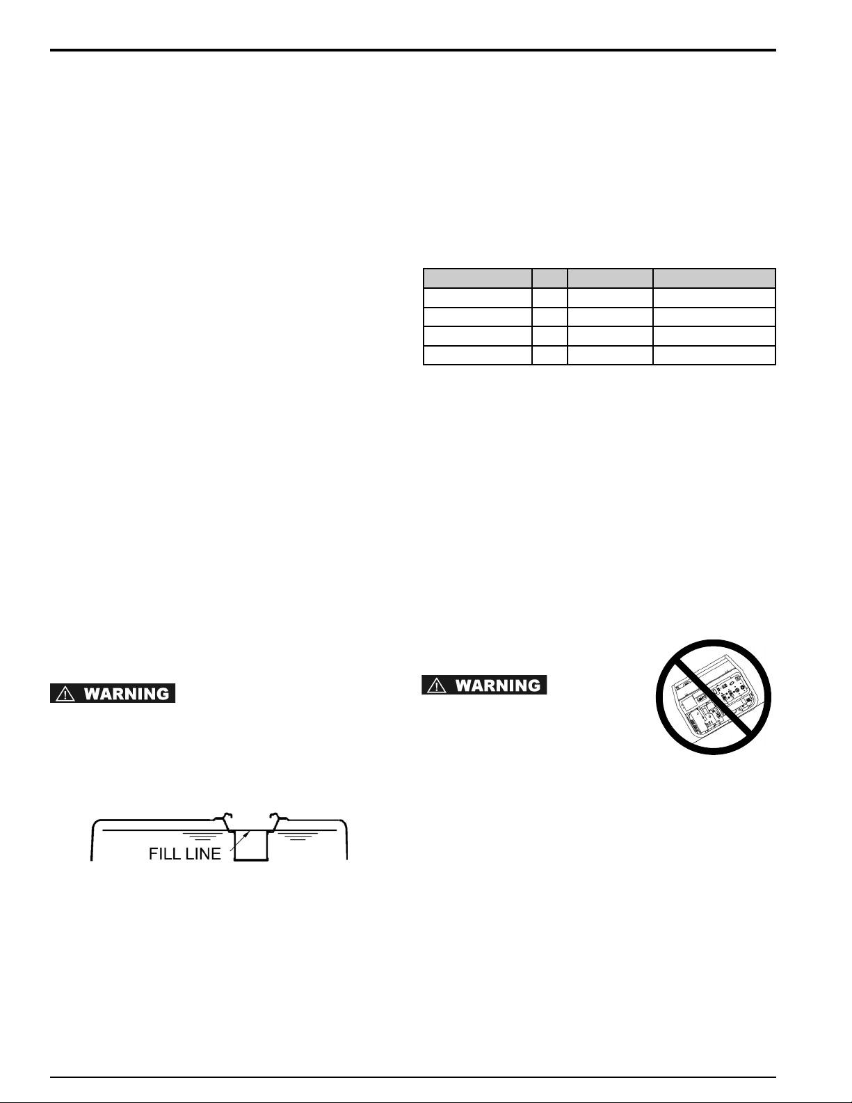
• SLOWLY ADD UNLEADED GASOLINE TO FUEL
TANK
• DO NOT OVERFILL TANK
• DO NOT FILL ABOVE TOP OF FUEL SCREEN. THIS
WILL ALLOW EXPANSION IN HOT WEATHER AND
PREVENT OVERFLOW.
ENGINE OIL
The engine manual or other information provided by the engine
manufacturer supersedes data provided here. Proper oil grade
varies with climate. The grade listed in the table is typically a
good grade but consult the engine manual to verify proper
grade. The oil fill ports are located on both sides of the engine.
The gray filler cap has an integral dipstick. Add the proper
amount of oil and check the level using the dipstick. NOTE:
The dipstick should be placed into the filler opening but not
screwed in to check the level.
STARTING BATTERY (Electric Start Models Only)
The starting battery should be rated at 12V-18AH (12V-34AH
for DXGN14000). The battery is fully charged if a voltage of
13.7VDC is measured across the terminals using a DC
Voltmeter.
POSITIONING
• Place the generator set on a flat and solid surface to
prevent it from sinking.
• Keep fuel, oil or other flammable or combustible materials
at a safe distance from the generator set.
• Select a site that is well ventilated and protected from the
weather.
• Place the generator set safely away from people and
animals.
TILTING CAN
CAUSE FUEL SPILLAGE
OPERATION
Check the engine oil before each use. Never operate the
generator set with insufficient oil.
GENERATOR SET OVERLOAD
Do not exceed the rated load of the generator set when
operating continuously. Before connecting items to the
generator set, determine the total electrical requirements of the
products to be connected. The requirement of each item is
generally given on the manufacturer’s nameplate. Following is
a list of commonly used items and typical requirements. Use
this list as a guideline only if no other data is available.
OPERATION
GENERAL INFORMATION
This manual has been prepared to acquaint you with the operation and maintenance of this product. Study the
information provided carefully to avoid problems associated with improper application or maintenance. Upon receipt
of your generator, verify that it is complete and in good condition.
The generator is comprised of a 4 stroke, air-cooled engine directly coupled to a 2 pole alternator producing either
125VAC or 125/250VAC depending on model. The no-load speed is approximately 3750rpm with the speed under
load going to approximately 3600rpm thus producing a frequency of 60Hz.
ENGINE HP Oil Capacity Grade
Honda GX270 8.5 1.16 qt (1.1 l) API SJ SAE 10W-30
Honda GX340 10.7 1.16 qt (1.1 l) API SJ SAE 10W-30
Honda GX390 11.7 1.16 qt (1.1 l) API SJ SAE 10W-30
Honda GX630 20.2 2.1 qt (2.0 l) API SJ SAE 10W-30
NOTE: Many appliances such as saws or drills draw more
current than indicated on the manufacturer’s nameplate when
under severe load.
STARTING THE GENERATOR SET
Before attempting to start the generator set, ensure that all
instructions given in previous sections have been followed
completely.
• Check oil and fuel levels.
• Turn the fuel shut-off valve on.
• Move the choke lever on the front of the engine on. Note:
the choke may not be required when the engine is warm
or in high ambient temperatures.
• Turn idle-control On/Off switch OFF.
RECOIL START
• Move engine On/Off switch to On position.
• Slowly pull recoil cord until resistance is felt and then pull
firmly. Let the recoil rewind slowly to avoid damage.
• Return the choke to the original position.
ELECTRIC START (DXGN7200)
• Move engine On/Off switch to On position.
• Push and hold the On/Off switch in the Start position until
the engine starts and release. Note: If the engine does not
start after 5 seconds, stop and wait 10 seconds and repeat
this step.
• Return the choke to the original position.
ELECTRIC START (DXGN14000)
• Turn the key switch to "START". Release key switch after
the engine starts.
• Return the choke to the original position.
CAUTION: This generator is equipped with an oil protection
system. When oil levels are too low for safe operation the
engine will shut down and/or will not start until the oil level is
corrected.
OPERATING THE GENERATOR SET
Once started, allow the engine to stabilize for approximately 3
minutes. Check that the circuit breakers and the GFCI
receptacles are not tripped. Turn the idle-control switch to the
On position if this feature is to be utilized. Set the voltage
selector switch to the appropriate mode, either 120V or
120/240V. See the guides below for more information on the
idle-control and voltage selector features.
IDLE CONTROL GUIDE (applicable models)
The automatic idle control system is available on some
generators. This feature allows the engine to automatically idle
down when there is no load drawn against the generator thus
saving fuel, decreasing wear and lowering the noise level.
There is an on-off switch located on the control panel that
activates or deactivates this feature. In the on position the
engine will idle down after detection of less than 40 Watts. The
engine will return to the correct running speed immediately
when a load of 350 Watts or more is applied. For applications
with loads less than 50W or with near constant loads, such as
home back up, it is best to turn the idle control feature off. The
feature should be turned off before starting or stopping the
generator and turned on when there will be extended periods
of inactivity for the generator.
Model DXGN14000: A 12V battery must be installed in
order for the idle control to function.
VOLTAGE SELECTOR GUIDE (applicable models)
The voltage selector switch allows the generator set to produce
120 volts only or to produce 120/240 volts simultaneously. With
the switch in the 120V position only the 120V receptacles may
be used. All of the power from the generator is available at 120
volts but the 240V output is not available. In the 120/240V
position all receptacles are operable however only half of the
generator output is available at any one 120V receptacle. Full
power may be pulled from the generator from the 240V
receptacle. The switch should always be left in the 120V
position when 240 volts are not needed. This balances the load
on the generator more effectively.
STOPPING THE GENERATOR SET
Unplug all appliances and let the engine run unloaded for a
couple of minutes. Turn the engine On/Off switch or key switch
to the Off position. Turn the fuel shut-off valve to the Off
position.
Never use the choke to stop the engine.
13
0068660
Item Running Watts
Air Conditioner (12000 Btu) (*) . . . . . . . . . . . . . . . . . . .1750
Air Compressor (1/2 hp) (*) . . . . . . . . . . . . . . . . . . . . . .1400
Air Compressor (3/4 hp) (*) . . . . . . . . . . . . . . . . . . . . . .1800
Air Compressor (1 hp) (*) . . . . . . . . . . . . . . . . . . . . . . .2000
Battery Charger (25A) . . . . . . . . . . . . . . . . . . . . . . . . . . .600
Belt Sander (3” belt) . . . . . . . . . . . . . . . . . . . . . . . . . . .1000
Circular Saw (7 1/4”) . . . . . . . . . . . . . . . . . . . . . . . 825-1050
Coffee Maker . . . . . . . . . . . . . . . . . . . . . . . . . . . . . 900-1100
Edger (lawn) . . . . . . . . . . . . . . . . . . . . . . . . . . . . . . . . . . .550
Furnace Fan (1/3 hp) (*) . . . . . . . . . . . . . . . . . . . . . . . . .1200
Hot Plate (single) . . . . . . . . . . . . . . . . . . . . . . . . . . . . . .1500
Impact wrench . . . . . . . . . . . . . . . . . . . . . . . . . . . . . . . . .600
Light Bulb . . . . . . . . . . . . . . . . . . . . . . . . . . . . . . .Bulb rating
Nail Gun . . . . . . . . . . . . . . . . . . . . . . . . . . . . . . . . . . . . .1200
Microwave . . . . . . . . . . . . . . . . . . . . . . . . . . . . . . . . . . . .750
Paint Sprayer (1/3 hp) (*) . . . . . . . . . . . . . . . . . . . . . . . .650
Paint Sprayer, hand-airless . . . . . . . . . . . . . . . . . . . . . . .175
Radio . . . . . . . . . . . . . . . . . . . . . . . . . . . . . . . . . . . . . .50-200
Refrigerator (*) . . . . . . . . . . . . . . . . . . . . . . . . . . . . . . . . .600
Table Saw (10”) (*) . . . . . . . . . . . . . . . . . . . . . . . . . . . . .2000
Television . . . . . . . . . . . . . . . . . . . . . . . . . . . . . . . . . .250-550
Weed Trimmer . . . . . . . . . . . . . . . . . . . . . . . . . . . . . . . . .500
Note: (*) Items allow at least 3 times the listed wattage for
starting.
GENERAL WATTAGE GUIDE
English
NOTICE:
0068660
14
English
GENERATOR APPLICATION
WHAT IS A GENERATOR
A generator is basically a prime mover, typically a gasoline or
diesel engine, coupled to an alternator to produce electricity. It
is very useful as a substitute power source during power
outages or as the primary source in remote locations where
power is not available. Generators are essential for people
such as contractors or farmers who are always in need of
portable power. They are also very convenient for recreational
use.
SELECTING A GENERATOR
Selecting the proper generator is important. A generator that is
too small for your application will not run all of the equipment
needed. A generator that is too large will cost more and if
never used to its potential the money is wasted. The correct
size generator is determined by totaling the wattage
requirements of the items to be used simultaneously,
determine additional starting wattage requirements and total
these numbers. Select a generator with a continuous rating
that exceeds this by about 20% to allow for expansion. See the
table in the section titled “Generator Set Overload” for some
wattage guidelines of common equipment.
RATED vs. SURGE WATTS
Rated
, or continuous, watts are the watts an item needs as it is
running.
Surge
, or maximum, watts are the watts an item needs to start.
This is typically 2-4 times the rated watts.
This information is typically provided on the manufacturer’s
nameplate. If watts are not provided, it can be calculated using
the formula: Watts=Amps x Volts.
EXTENSION CORDS
An extension cord should always be in good condition with no
damage to the wires or sheathing. Never run an extension cord
through water. The correct wire size for an extension cord can
be determined from the table that follows.
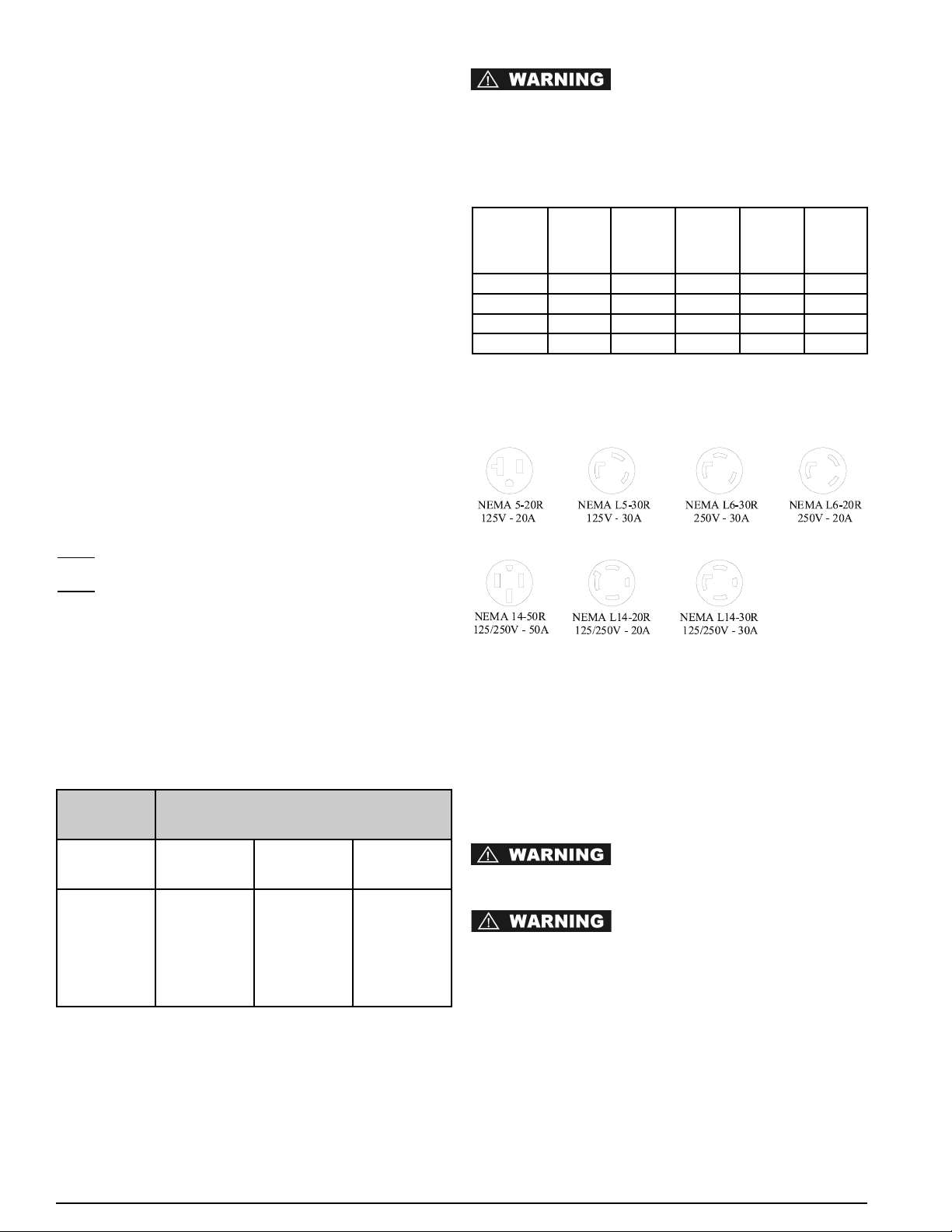
LOADING YOUR GENERATOR SET
With reference to the Receptacle details section, please review
the power receptacles fitted to your generator. The circuit
breaker rating and the generator rating drive the actual load
that may be pulled from each receptacle. The ratings shown in
the table are the maximum available from each receptacle.
DO NOT EXCEED THE INDIVIDUAL
RECEPTACLE RATINGS AS SHOWN IN THE TABLE BELOW.
DO NOT EXCEED THE TOTAL GENERATOR NAMEPLATE
RATING. All generator units are equipped with a
thermal-magnetic main circuit breaker as well as a "PUSH TO
RESET" breaker on branch circuits.
AMPERAGE RATE TABLE
* With voltage selector in 120V mode
ENGINE LIMITATIONS ON GENERATOR
PERFORMANCE
Generator ratings assume 60°F (20C) and Sea Level.
Operation of your generator at temperatures above 60°F (20C)
or above Sea Level will result in lower electrical output.
Electrical output must be derated 1% for each 10°F above
60°F and 3 ½ % for each 1000 feet above mean sea level.
GENERATOR CLEANING
ALWAYS SHUT DOWN THE
GENERATOR AND ALLOW IT TO COOL COMPLETELY
BEFORE PERFORMING CLEANING OPERATIONS.
DO NOT USE HIGH PRESSURE
WATER OR A GARDEN HOSE TO CLEAN YOUR
GENERATOR. WATER INTRODUCED INTO THE
GENERATOR CAN CAUSE ELECTRICAL SHORTS,
GENERATOR DAMAGE OR PERSONAL INJURY.
• Compressed air (max. 25 psi) may be used to blow loose
dirt and dust from your generator. DO NOT DIRECT
COMPRESSED AIR DIRECTLY INTO ANY OPENING IN
THE GENERATOR OR ENGINE.
• Use a dampened cloth to wipe clean exterior surfaces.
• Use a soft bristle brush to clean/ loosen heavy dirt, oil or
grease deposits.
• NEVER insert rags, tools or any device into the generator
or engine openings.
Model NEMA
5-20R
125V
GFCI
NEMA
L5-30R
125V
Twistlock
NEMA
L14-20R
125/250V
Twistlock
NEMA
L14-30R
125/250V
Twistlock
NEMA
14-50R
125/250V
DXGN4500 20 Amps 30 Amps* 20 Amps* NA NA
DXGN6000 20 Amps 30 Amps* NA 30 Amps* NA
DXGN7200 20 Amps 30 Amps NA 30 Amps NA
DXGN14000
20 Amps NA NA 30 Amps 50 Amps
Continuous
Load
Minimum Cord Gauge (AWG)
Amps 0-50 Feet 50-100 Feet 100-150
Feet
20
25
30
35
40
50
12
12
10
10
8
6
10
10
8
8
6
4
8
6
6
4
2
2
RECEPTACLE DETAILS
The receptacles shown in this section are for reference only.
Each receptacle is not available on all generators.

15
0068660
GENERAL STORAGE GUIDELINES
GASOLINE FUEL FUMES ARE
FLAMMABLE. DO NOT STORE YOUR GENSET IN ANY
AREA THAT IS INDOOR OR IN POORLY VENTILATED
AREAS. GASOLINE FUEL FUMES CAN IGNITE IN THE
PRESENCE OF ANY OPEN FLAME, PILOT LIGHT, CLOTHES
DRYER, WATER HEATER, ETC.
Your generator should be started and operated for
several minutes at least every 30 days. When the generator
set is not being operated or is being stored more than one
month, follow these instructions:
1. Replenish engine oil to upper level.
2. Run the generator, then close the fuel shut-off valve and
allow the unit to run until the engine stops.
3. Move the engine switch to the “OFF” position. (Turn
the key switch to “OFF” on the DXGN14000 model).
4. After the unit has cooled, drain gasoline from fuel tank,
fuel line and carburetor.
5. Pour about one teaspoon of engine oil through the spark
plug hole, pull the recoil starter several times and replace
the plug. Then pull the starter until you feel the piston is
on its compression stroke and leave it in that position. This
closes both the intake and exhaust valves to prevent the
inside of the cylinder from rusting.
6. Cover the unit and store in a clean, dry place that is well
ventilated away from open flame or sparks.
We recommend always using a fuel
stabilizer. A fuel stabilizer will minimize the formulation of
fuel gum deposits during storage. The fuel stabilizer can
be added to the gasoline in the fuel tank, or into the
gasoline in a storage container.
English
GENERAL MAINTENANCE
Proper maintenance and service are required to achieve maximum engine life and maintain warranty. The following tables provide
engine specifications as well as maintenance schedules for the generator engines. Note that the generator models are
referenced with the engine model. An engine owner's manual is provided with each machine that also provides basic
maintenance and troubleshooting information. Defer to the engine manufacturers manual if any discrepancies appear between
the data provided in this manual and the engine owner's manual. Full engine service manuals are available from American Honda
Motor Co., 4900 Marconi Drive, Alpharetta, GA 30005-8847, (800) 910-1293.
ENGINE SPECIFICATIONS AND CAPACITIES
Model GX270 (DXGN4500) GX340 (DXGN6000) GX390 (DXGN7200) GX630 (DXGN14000)
Type 4-stroke, overhead vale single cylinder, inclined 25°
4-stroke, overhead valve,
V-Twin
Displacement 270cc (16.5 cu in) 389cc (23.7 cu in) 389cc (23.7 cu in) 688cc (42.0 cu in)
Bore and Stroke
73 x 58 mm
(2.9 x 2.3 in)
88 x 64 mm
(3.5 x 2.5 in)
88 x 64 mm
(3.5 x 2.5 in)
78 x 72 mm
(3.1 x 2.8 in)
Net HP 8.5 hp @3600rpm 10.7 hp @3600rpm 11.7 hp @3600rpm 20.2hp @3600rpm
Net Torque
14.1ft-lb @2500rpm 19.5ft-lb @2500rpm 19.5ft-lb @2500rpm 35.1ft-lb @2500rpm
Compression Ratio 8.5 : 1 8.2 : 1 8.2 : 1 9.3 : 1
Cooling System Forced-air
Ignition System Transistorized magneto
Ignition Timing
25° B.T.D.C. (fixed)
Spark Plug BPR6ES (NGK), W20EPR-U (Nippondenso)
Carburetor Horizontal type, butterfly valve
Air Cleaner Dual element type
Lubricating System Splash Forced Oil
Oil Capacity 1.1l (1.16 US qt) 1.1l (1.16 US qt) 1.1l (1.16 US qt) 2.0 l (2.1 US qt)
Starting System Recoil Recoil Recoil/Electric Electric
Stopping System Ignition primary circuit ground
Fuel Type Unleaded gasoline (86 pump octane)
PTO Shaft Rotation Counterclockwise (from PTO side)
Dry Weight 25.0 kg (55.1 lb) 31.5 kg (69 lb) 31.5 kg (69 lb) 44.0 kg (96.8 lb)
NOTICE:
16
English
OIL SELECTION
Proper oil selection as well as proper oil level is critical to achieve maximum engine life. Use high detergent, premium quality
motor oil certified for service class SJ that should be designated on the container. SAE 10W-30 is recommended for
general, all temperature use. Use the table below to select the proper oil for the temperature in your area.
Viscosity -30C/-22F -20C/-4F -10C/14F 0C/32F 10C/50F 20C/68F 30C/86F 40C/104F
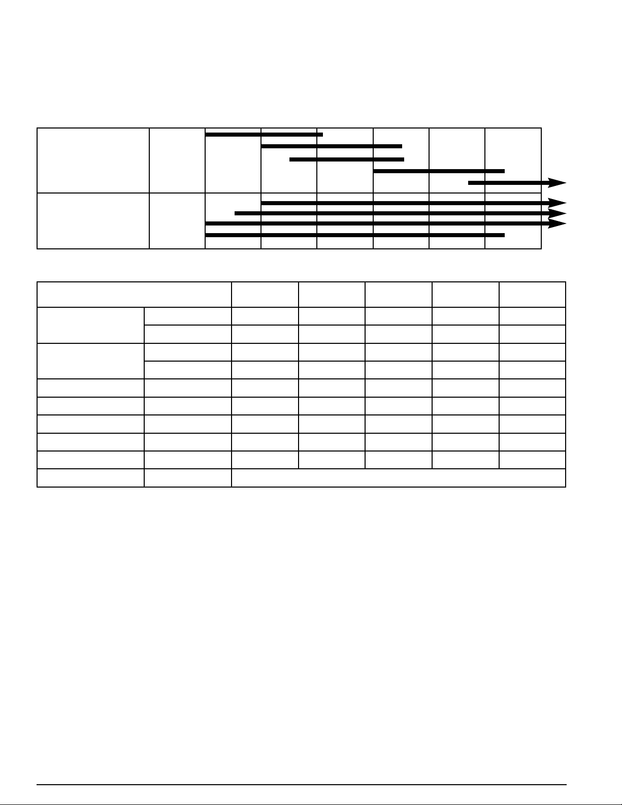
ENGINE MAINTENANCE SCHEDULE
Notes:
(1) Service more frequently in dusty areas.
(2) Should be serviced by authorized dealer unless owner has proper tools and is mechanicaly proficient. See
engine Shop Manual for instructions.
DAILY INSPECTION
1. Recoil Starter Cord
2. Engine Oil Level
3. Check for Engine Oil or Fuel Leaks
4. Inspect Spark Plug Cables
5. Inspect Cooling System for Cleanliness
6. Listen for Abnormal Noise
7. Look for Abnormal Vibration
Single 10W
20W
20
30
40
Multi 20W-40, 20W-50
15W-40, 15W-50
10W-40
10W-30
ITEM
Each Use First Month
Or 20 Hrs
3 Months Or
50 Hrs
6 Months Or
100 Hrs
Every Year
Or 300 Hrs
Oil
Check X
Change X X
Air Cleaner
Check X
Clean X (1)
Sediment Cup Clean X
Spark Plug Check-Clean X
Spark Arrester Clean X
Valve Clearance Check-Adjust X (2)
Fuel Tank and Strainer Clean X (2)
Fuel Line Check Replace as necessary.
0068660
17
0068660
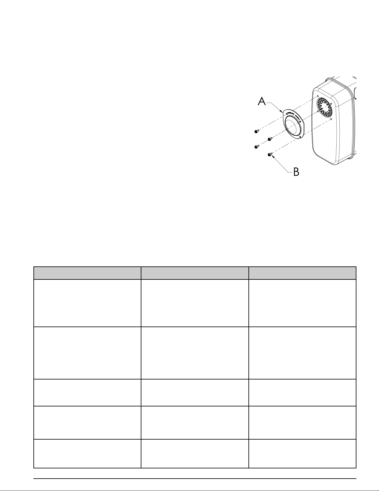
SPARK ARRESTER
The spark arrester must be serviced every 100 hours to keep it functioning as designed.
If the engine has been running, the muffler will be hot. Allow it to cool before servicing the spark arrester.
DXGN4500, DXGN6000, and DXGN7200
Clean and inspect the spark arrester as follows:
1. Remove the four screws (B) and spark arrester screen (A)
from the muffler.
2. Use a brush to remove carbon deposits from the spark
arrester screen. Be careful to avoid damaging the screen.
3. The spark arrester must be free of breaks and holes.
Replace the spark arrester if it is damaged.
4. Attach the spark arresting screen (A) to the muffler by
aligning the holes in the screen with the holes pierced in
the muffler. Thread the four screws (B) into the holes and
tighten securely.
DXGN14000
See instructions supplied with Spark Arrestor Kit.
FAULT FINDING GUIDE
English
SYMPTOMS PROBABLE CAUSES CORRECTION
ENGINE WILL NOT START 1. Oil level too low.
2. No fuel or valve(s) turned off.
3. Start switch turned Off.
4. Blocked or leaking fuel system.
5. Clogged air filter.
6. Genset under load at start-up.
1. Add oil.
2. Add fuel and/or turn valve(s) on.
3. Turn switch On.
4. Repair fuel system.
5. Clean or replace air filter.
6. Disconnect load.
NO POWER OUTPUT 1. Circuit breaker tripped.
2. GFCI receptacle tripped.
3. Faulty circuit breaker.
4. Faulty receptacle.
5. Faulty capacitor in alternator.
6. Faulty diodes in alternator.
7. Failure in alternator windings.
1. Reset circuit breaker.
2. Reset GFCI receptacle.
3. Replace circuit breaker.
4. Replace receptacle.
5. Replace capacitor.
6. Replace diodes.
7. Repair or replace alternator.
NOISY MACHINE 1. Damaged bearing.
2. Damaged exhaust system.
3. Loose or rattling parts.
1. Replace bearing.
2. Repair or replace.
3. Repair loose or rattling parts.
OVERHEATING 1. Ventilation openings blocked.
2. Overload.
3. Ambient temperature too high.
1. Clear ventilation openings.
2. Verify load levels.
3. Provide better ventilation for
cooling.
CIRCUIT BREAKER TRIPS 1. Overloaded circuit.
2. Faulty equipment or cable.
3. Faulty circuit breaker.
1. Reduce load.
2. Check, repair or replace.
3. Replace circuit breaker.
18
DIRECTIVES EN MATIÈRE DE SÉCURITÉ ET DÉFINITIONS
Ce manuel d'instructions contient des renseignements
importants que vous devez connaître et comprendre afin
d'appliquer et d'utiliser votre générateur de manière correcte,
efficace et en toute sécurité. Tous les opérateurs, utilisateurs et
propriétaires ultérieurs de ce générateur doivent lire et
comprendre toutes ces instructions avant d'utiliser l'appareil.
Conservez ces instructions à titre de référence ultérieure.
Pour vous permettre de reconnaître les renseignements
importants relatifs à VOTRE SÉCURITÉ et à la PRÉVENTION
D'ÉVENTUELS PROBLÈMES, nous utilisons les symboles
ci-dessous.
Indique une situation dangereuse
imminente qui, si elle n’est pas évitée, causera la mort ou des
blessures graves.
Indique une situation
potentiellement dangereuse qui, si elle n’est pas évitée,
pourrait se solder par un décès ou des blessures graves.
Indique une situation potentiellement
dangereuse qui, si elle n’est pas évitée pourrait se solder par
des blessures mineures ou modérées.
Indique une pratique ne posant aucun risque
de dommages corporels mais qui par contre, si rien n’est fait
pour l’éviter, pourrait poser des risques de dommages
matériels.
RÈGLES DE SÉCURITÉ
RISQUE D'ASPHYXIE
NE PAS FAIRE FONCTIONNER LA
GÉNÉRATRICE DANS UN ENDROIT CLOS. LE TUYAU
D'ÉCHAPPEMENT DE LA GÉNÉRATRICE ÉMET DU
MONOXYDE DE CARBONE MORTEL. L'EXPOSITION AU
MONOXYDE DE CARBONE PEUT CAUSER UN
EMPOISONNEMENT, DES MAUX DE TÊTES, DES
NAUSÉES, DES MALADIES SÉVÈRES OU LA MORT.
RISQUE D’ÉLECTROCUTION OU CHOC
CET ENSEMBLE DE GÉNÉRATRICE
PRODUIT DU COURANT. PAR CONSÉQUENT, LES RÈGLES
DE SÉCURITÉ DOIVENT ÊTRE RESPECTÉES. L'USAGE
INAPPROPRIÉ DE CETTE GÉNÉRATRICE PEUT
PROVOQUER UNE ÉLECTROCUTION, DES BLESSURES
OU LA MORT. NE PAS OPÉRER, FAIRE L'ENTRETIEN OU
RÉPARER LA GÉNÉRATRICE SANS POSSÉDER TOUTES
LES QUALIFICATIONS NÉCESSAIRES.
CET ENSEMBLE DE GÉNÉRATRICE
EST CONÇU POUR FONCTIONNER UNIQUEMENT À
L'EXTÉRIEUR DANS DES CONDITIONS SÈCHES. NE
JAMAIS LA FAIRE FONCTIONNER À L'INTÉRIEUR. NE
JAMAIS FAIRE FONCTIONNER LA GÉNÉRATRICE SOUS LA
PLUIE, DANS LA NEIGE, LE GRÉSIL OU TOUTES AUTRES
CONDITIONS NORMALEMENT MOUILLÉES. DES
DOMMAGES À LA GÉNÉRATRICE, DES BLESSURES
PHYSIQUES OU LA MORT POURRAIENT RÉSULTER D'UNE
ÉLECTROCUTION.
SI CETTE GÉNÉRATRICE EST
BRANCHÉE À UN ÉDIFICE, UNE MAISON, UN COMMERCE
OU TOUT AUTRE CIRCUIT ÉLECTRIQUE NORMALEMENT
ALIMENTÉ PAR LE SERVICE COURANT, LES ÉTAPES
DOIVENT ÊTRE SUIVIES POUR S'ASSURER QUE LA
SORTIE ÉLECTRIQUE DE LA GÉNÉRATRICE ET LE
COURANT UTILISÉ SOIENT POSITIVEMENT ISOLÉS.
FRENCH INSTRUCTIONS
SÉCURITÉ
Certains États et juridictions exigent que les équipements
motorisés soient munis de silencieux coupe étincelles.
Certains modèles ne sont pas équipés de silencieux coupe
étincelles. Si tel est le cas et que les silencieux coupe
étincelle sont obligatoires dans votre localité, contacter votre
distributeur local pour connaître les instructions concernant
la modification à apporter.
SILENCIEUX COUPE ÉTINCELLES
Le système de contrôle des émissions d'échappement de
cette génératrice est conforme aux exigences établies par la
California Air Resources Board (CARB) et le Environmental
Protection Agency (EPA). Les manufacturiers des moteurs
respectifs administrent la garantie du système
d'échappement. Consulter la documentation du moteur pour
des renseignements additionnels concernant la garantie.
SYSTÈME DE CONTRÔLE DES ÉMISSIONS
D'ÉCHAPPEMENT
Français
S’il doit être utilisé à proximité de matériaux inflammables tels
que récoltes, forêts, broussailles, herbes ou autres, il est
fortement recommandé d’installer un pare-étincelles, par
ailleurs obligatoire en Californie. Les articles de la loi
californienne relatifs à l’usage de pare-étincelles sont les
suivants : 13005(b), 4442 et 4443. L’usage d’un pare-étincelles
est également exigé sur certains des territoires du service des
Forêts américain et peut également l’être par d’autres lois et
règlements. Un pare-étincelles homologué est disponible
auprès de notre concessionnaires ou peut être commandé à
D
EWALT Industrial Tool Co., 701 East Joppa Road, Baltimore,
MD 21286. Téléphone : 1-888-431-6871.
PARE-ÉTINCELLES
0068660
AVIS :
Le tuyau d'échappement de ce produit contient des
produits chimiques qui sont reconnus par l'État de
Californie comme pouvant causer le cancer, des
anomalies congénitales ou d'autres problèmes
reproductifs.
19
0068660Français
POUR CE FAIRE, UTILISER UN INTERRUPTEUR
PROPREMENT INSTALLÉ. NE PAS ISOLER LA SOURCE ET
LE SYSTÈME ÉLECTRIQUE DE LA GÉNÉRATRICE
POURRAIT ABÎMER CELLE-CI ET OCCASIONNER DES
BLESSURES OU LA MORT.
POUR ÉVITER LES RETOURS DE
COURANT DANS LE SECTEUR, IL EST NÉCESSAIRE
D’ASSURER L’ISOLATION ÉLECTRIQUE DE LA MAISON.
AVANT D’EFFECTUER LA CONNEXION TEMPORAIRE DU
GÉNÉRATEUR SUR L’INSTALLATION ÉLECTRIQUE DE LA
MAISON, COUPER LE COURANT À L’INTERRUPTEUR
PRINCIPAL. AVANT DE RÉALISER DES CONNEXIONS
PERMANENTES, INSTALLER UN COMMUTATEUR DE
TRANSFERT À DEUX DIRECTIONS. POUR ÉVITER TOUTE
ÉLECTROCUTION OU DES DOMMAGES MATÉRIELS,
FAIRE CONNECTER LE GÉNÉRATEUR À L’INSTALLATION
ÉLECTRIQUE DE LA MAISON PAR UN ÉLECTRICIEN
QUALIFIÉ. LES LOIS CALIFORNIENNES EXIGENT
L’ISOLATION DE L’INSTALLATION ÉLECTRIQUE DE LA
MAISON AVANT D’Y CONNECTER UN GROUPE
ÉLECTROGÈNE. IL N'EST PAS RECOMMANDÉ DE
PROCÉDER AU RACCORDEMENT TEMPORAIRE DE
L'APPAREIL EN RAISON DE LA RÉALIMENTATION.
TOUJOURS OBSERVER LES CODES ET RÈGLEMENTS
LOCAUX QUI S'APPLIQUENT À L'INSTALLATION DE TOUT
APPAREIL COMPATIBLE AVEC CE PRODUIT.
1. NFPA 70 - Code national de l'électricité.
2. NFPA 37 - Norme d'installation et d'utilisation des
moteurs fixes à combustible.
3. Manuel de câblage du réseau d'alimentation de
secours des appareils agricoles.
NE PAS MODIFIER OU NE PAS FAIRE
UN USAGE INAPPROPRIÉ DE VOTRE GÉNÉRATRICE.
TOUTE UTILISATION AUTRE QUE CELLES POUR
LESQUELLES LA GÉNÉRATRICE EST CONÇUE PEUVENT
CONDUIRE À UN BRIS DE LA GÉNÉRATRICE, DES
BLESSURES PHYSIQUES OU LA MORT PAR
ÉLECTROCUTION.
NE JAMAIS TOUCHER À UN
RÉCEPTACLE OU À UN FIL DÉNUDÉ CAR IL Y A UN
RISQUE D'ÉLECTROCUTION.
RISQUE D’EXPLOSION OU D’INCENDIE
VOUS ASSURER QU'IL Y A UN
ESPACE D'AU MOINS 6 PIEDS DE CHAQUE CÔTÉ DE LA
GÉNÉRATRICE PENDANT TOUTE LA DURÉE
D'UTILISATION. NE PAS LAISSER L'ESPACE NÉCESSAIRE
POURRAIT ENDOMMAGER VOTRE GÉNÉRATRICE ET
POTENTIELLEMENT CAUSER UN INCENDIE.
L'ESSENCE EST HAUTEMENT
INFLAMMABLE ET SES VAPEURS SONT TRÈS
EXPLOSIVES. NE PAS MANIPULER CONVENABLEMENT
DE L'ESSENCE PEUT RÉSULTER EN UNE EXPLOSION OU
UN INCENDIE. NE PERMETTEZ PAS QUE L'ON FUME À
MOINS DE 50 PIEDS DE LA GÉNÉRATRICE.
NE JAMAIS REMETTRE DE
L'ESSENCE LORSQUE LA GÉNÉRATRICE EST CHAUDE.
NE JAMAIS REMPLIR LA GÉNÉRATRICE LORSQU'ELLE
FONCTIONNE. RENVERSER DE L'ESSENCE SUR LE
MOTEUR OU LA GÉNÉRATRICE PEUT CAUSER UNE
EXPLOSION OU UN INCENDIE. TOUJOURS ATTENDRE
QUE L'ENSEMBLE DE LA GÉNÉRATRICE SOIT REFROIDI
AVANT LE REMPLISSAGE.
NE PAS ENTREPOSER LA
GÉNÉRATRICE DANS UN ENDROIT OÙ DES VAPEURS
D'ESSENCE PEUVENT ÊTRE EN CONTACT AVEC DES
ÉTINCELLES, UN PILOTE OU UNE FLAMME VIVE.
L'ENTREPOSAGE INADÉQUAT DE CETTE GÉNÉRATRICE
PEUT CAUSER UNE EXPLOSION OU UN INCENDIE.
INSPECTER LE COUPE
ÉTINCELLES PÉRIODIQUEMENT. IL EST REQUIS DANS
CERTAINES RÉGIONS ET MINIMISE LES RISQUES D'IN-
CENDIE CAUSÉS PAR LES ÉTINCELLES PROVENANT DU
TUYAU D'ÉCHAPPEMENT.
PRUDENCE: NE PAS FAIRE
FONCTIONNER SI LA TEMPÉRATURE AMBIANTE EXCÈDE
104ºF/40ºC.
NE PAS DÉPASSER LA
CAPACITÉ DE LA GÉNÉRATRICE. LA CHARGE
ÉLECTRIQUE DE CHAQUE PRISE DOIT-ÊTRE
ADDITIONNÉE POUR CONNAÎTRE LA CHARGE
ÉLECTRIQUE TOTALE ET ELLE NE DOIT PAS DÉPASSER
LA CAPACITÉ DÉTERMINÉE DE LA GÉNÉRATRICE.
SI L'APPAREIL UTILISÉ N'AFFICHE PAS LES WATTS, MAIS
SEULEMENT L'AMPÉRAGE, LES WATTS PEUVENT-ÊTRE
CALCULÉS EN MULTIPLIANT L'AMPÉRAGE PAR LE
VOLTAGE (WATTS = AMPÈRES X VOLTS).
SÉCURITÉ GENERALE
Toujours suivre les règles électriques Nationales et Locales
pertinentes à la génératrice. Les codes nationaux et locaux
remplacent les règles ou les informations contenus dans ce
manuel.
REFÉREZ-VOUS AUX RÈGLES
ELECTRIQUES LOCALES ET NATIONALES POUR
DÉTERMINER CE QUI EST NÉCCÉSSAIRE POUR
EFFECTUER LA MISE À LA TERRE, CE QUI PEUT VARIER
D'UNE APPLICATION À UNE AUTRE. LA GÉNÉRATRICE
EST MISE À LA TERRE À L'INTÉRIEUR DE LA STRUCTURE.
DANS LES ENDROITS OU UNE MISE À LA TERRE
EXTERNE EST REQUISE, RACCORDER LA GÉNÉRATRICE
À UN CONDUCTEUR PHYSIQUE DE MISE À LA TERRE. UN
FIL DE CUIVRE SANS PLI, DE LONGUEUR CONTINUE
AYANT UN MINIMUM DE 6 AWG DOIT-ÊTRE UTILISÉ.
• Prendre les précautions nécessaires afin de ne pas
renverser de l'essence lorsque vous déplacez ou
transportez cette génératrice et faire toujours preuve d'un
bon jugement lorsque vous soulevez la génératrice. Un
nombre suffisant de personnes et une technique adéquate
doivent-être utilisés pour soulever la génératrice.
• Ne pas couvrir la génératrice pendant son fonctionnement
ou juste après son interruption. Il faut toujours allouer une
certaine période d'attente pour permettre le
refroidissement avant de couvrir la génératrice.
• Faire fonctionner la génératrice seulement si elle est en
bonne condition électrique et mécanique.
20
Français
• Toujours garder vos mains, autres parties du corps,
cheveux et vêtements loin des pièces rotatives de la
génératrice.
• Ne pas mettre la génératrice en marche avec un appareil
raccordé en mode " ON ". Être toujours certains que les
appareils utilisés sont disconnectés de la génératrice ou
en mode " OFF " (arrêt).
• L'utilisation de la génératrice au travail ou sur les sites de
construction peut nécessiter des réceptacles de
disjoncteur de fuite de terre (DFT).
• Utiliser uniquement des rallonges en bonne condition avec
mise à la terre et assurez-vous que le fil à l'intérieur de la
rallonge soit suffisamment gros pour transporter
sécuritairement l'intensité de courant produite par la
génératrice.
• Ne pas manipuler les rallonges électriques si elles sont
dans l'eau ou dans un endroit mouillé.
RISQUE DE BLESSURE CORPORELLE
GARDER VOS MAINS, PARTIES
DU CORPS, CHEVEUX OU VÊTEMENTS LOIN DES
PARTIES CHAUDES DE LA GÉNÉRATRICE PENDANT ET
APRÈS L'UTILISATION. LE SYSTÈME D'ÉCHAPPEMENT ET
LA GÉNÉRATRICE PEUVENT DEMEURER TRÈS CHAUDS,
MÊME APRÈS LA MISE EN ARRÊT.
NE PAS MODIFIER LA VITESSE
DU MOTEUR. LA GÉNÉRATRICE FONCTIONNE À UNE
VITESSE NOMINALE DE 3600 TR/MIN. UNE
AUGMENTATION DE LA VITESSE NOMINALE DE 3600
TR/MIN ACCROÎT LE RISQUE DE BLESSURES PHYSIQUES
CAUSÉES PAR LE CHOC ROTATIONEL DES MEMBRES
ROTATIFS. L'UTILISATION DE LA GÉNÉRATRICE À UNE
VITESSE NOMINALE INFÉRIEURE À 3600 TR/MIN PEUT
CAUSER DES DOMMAGES À LA GÉNÉRATRICE OU À
L'APPAREIL UTILISÉ EN RAISON DU BAS VOLTAGE.
PRÉCAUTIONS À PRENDRE AVEC LA BATTERIE
LES BATTERIES DE REMISAGE
PRODUISENT ET RELÂCHENT DES GAZ EXPLOSIFS
D'HYDROGÈNE LORSQU'ELLES SE RECHARGENT. LA
MOINDRE ÉTINCELLE, FLAMME OU TISON PEUT
ALLUMÉR CES GAZ ET PRODUIRE UNE SÉRIEUSE
EXPLOSION QUI POURRAIT CAUSER LA CÉCITÉ OU
D'AUTRES BLESSURES SÉRIEUSES. PORTER DES
VERRES DE SÉCURITÉ, UN TABLIER ET DES GANTS EN
CAOUTCHOUC LORSQUE VOUS TRAVAILLEZ PRÈS OU À
L'ENTRETIEN D'UNE BATTERIE. LE LIQUIDE CONTENU
DANS UNE BATTERIE EST DE L'ACIDE SULFURIQUE
EXTREMEMENT CORROSIVE ET PEUT CAUSER DES
BLESSURES SÉRIEUSES. TOUJOURS DÉBRANCHER LE
CÂBLE DU PÔLE NÉGATIF DE LA BATTERIE AVANT DE
FAIRE L'ENTRETIEN DE LA BATTERIE OU AVANT FAIRE
N'IMPORTE QUEL ENTRETIEN ÉLECTRIQUE SUR LA
GÉNÉRATRICE OU LE MOTEUR.
PROTECTION ENVIRONNEMENTALE
INSPECTER LE SYSTÈME
D'ÉCHAPPEMENT RÉGULIÈREMENT POUR VOUS
ASSURER QU'IL FONCTIONNE CORRECTEMENT. UN
TUYAU D'ÉCHAPPEMENT QUI FUIT AUGMENTE LE NIVEAU
DE BRUIT.
DIRIGER LE CÔTÉ " BRUYANT " DE
LA GÉNÉRATRICE VERS UN ENDROIT OUVERT. ÉVITEZ LA
RÉSONANCE D'UN MUR OU D'UN ÉDIFICE POUR NE PAS
AMPLIFIER LE SON.
NE JAMAIS VIDANGER L'HUILE DU
MOTEUR SUR LE SOL OU DANS LE SYSTÈME D'ÉGOUT.
ASSEMBLAGE DE LA BARRE DE LEVAGE
Fixez le crochet de levage (A) au dispositif de transport à l'aide
de boulons de 3/8 x 2,00" (B) et d'écrous nyloc de 3/8 (C)
comme indiqué dans l'illustration. Serrez les boulons
fermement.
SOULEVER OU SUSPENDRE LE GÉNÉRATEUR
Une fixation incorrecte des câbles,
chaînes ou sangles pour soulever le générateur peut
provoquer des dommages matériels, des blessures graves,
voire le décès, et annule la garantie du fabricant.
Toujours se servir de câbles,
chaînes ou sangles prévus pour une charge d’utilisation de
907,2 kg (2 000 lb) ou plus pour soulever ou suspendre le
générateur.
Ne jamais se servir du générateur
alors qu’ilest suspendu. Une telle pratique pourrait provoquer
des dommages matériels, des blessures graves, voire le
décès.
NE PAS suspendre des objets
autres que le générateur à partir de la barre de levage.
S’assurer que toute la quincaillerie
du cadre et de la barre de levage soit serrée.
Acheminer le câble,
chaîne ou sangle dans
la barre de levage
(A) comme indiqué.
TOUJOURS utiliser la
barre de levage pour
soulever ou suspendre
le générateur.
S’assurer que le générateur soit de niveau
avant de le soulever ou suspendre pour empêcher tout
dommage.
0068660
AVIS :
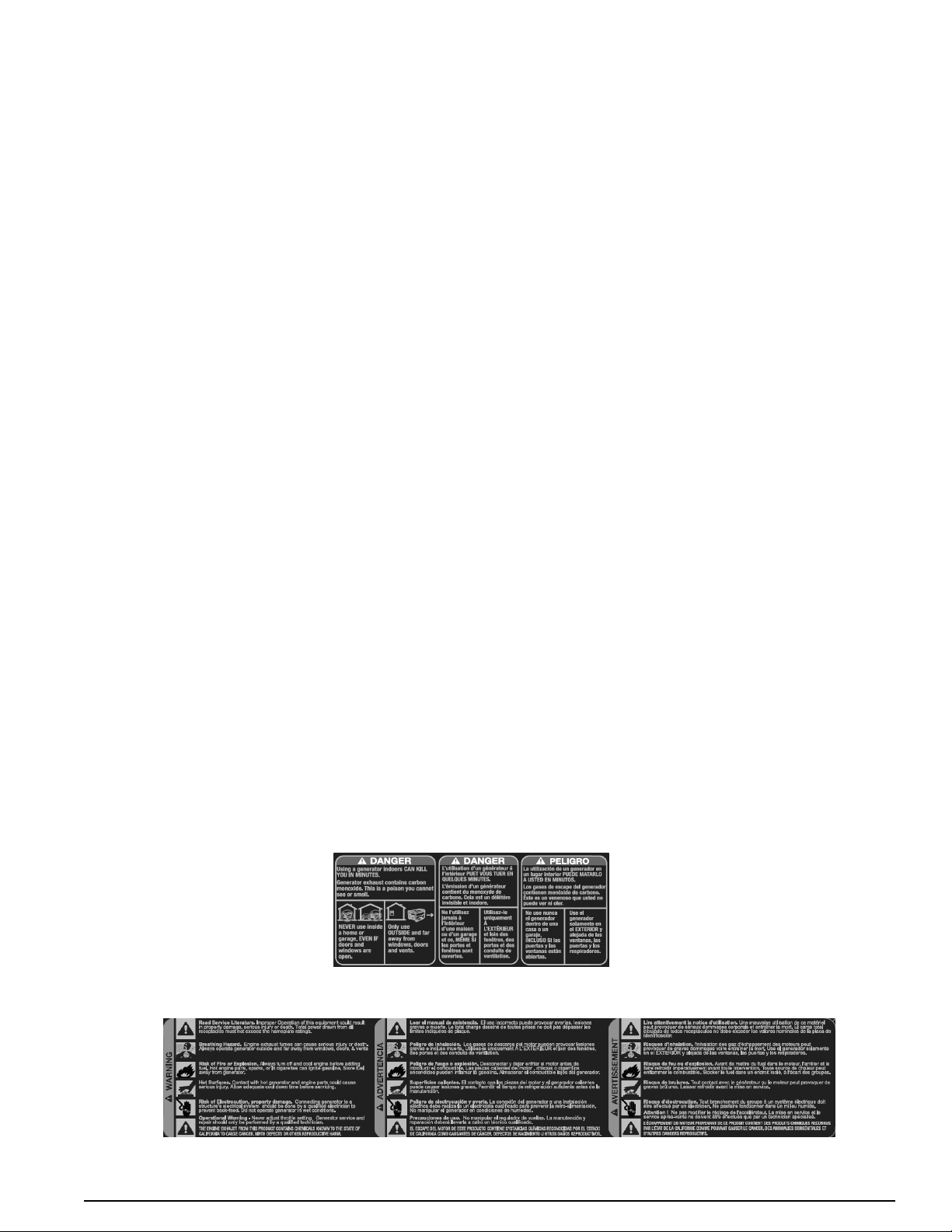
21
0068660Français
Accessoires
Les accessoires recommandés pour votre outil peuvent être achetés auprès du distributeur local ou d’un centre de
réparation agréé. Pour toute assistance en matière d’accessoires convenant à l’outil acheté, communiquer avec
DEWALT Industrial Tool Co., 701 East Joppa Road, Baltimore, MD 21286, États-Unis, composer le 1-888-431-6871
ou visiter notre site Web à www.dewalt.com.
Information sur les réparations
Veuillez recueillir les informations suivantes pour tous les appels au Service à la clientèle :
Numéro du modèle ___________________________________ Numéro de série ______________
Date et lieu de l’achat__________
Réparations
Pour assurer la SÉCURITÉ et la FIABILITÉ du produit, les réparations, l’entretien et les réglages doivent être
réalisés par un centre de réparation en usine de DEWALT, un centre de réparation agréé DEWALT ou par un
personnel de réparation professionnel. Toujours utiliser des pièces de rechange identiques.
Garantie complète de trois ans - Etats-Unis et Canada
Les générateurs D
EWalt de service intensif sont garantis pour trois (3) ans à partir de la date d’achat aux Etats-Unis
et le Canada. D
EWalt réparera gratuitement toutes les défectuosités provoquées par un défaut de matériel ou de
fabrication. Pour des renseignements relatifs aux réparations sous garantie, visiter le site Web www.dewalt.com ou
composer le 1-888-431-6871. Cette garantie ne s’applique pas aux accessoires ni aux dommages causés par des
réparations réalisées ou tentées par des tiers. Cette garantie vous accorde des droits légaux spécifiques et il est
possible que vous ayez d’autres droits qui varient d’un État ou d’une province à l’autre.
Garantie complète de un an - Mexique
Les générateurs DEWalt de service intensif sont garantis pour un (1) an à partir de la date d’achat au Mexique.
DEWalt réparera gratuitement toutes les défectuosités provoquées par un défaut de matériel ou de fabrication. Pour
des renseignements relatifs aux réparations sous garantie, visiter le site Web www.dewalt.com ou composer le
1-888-431-6871. Cette garantie ne s’applique pas aux accessoires ni aux dommages causés par des réparations
réalisées ou tentées par des tiers. Cette garantie vous accorde des droits légaux spécifiques et il est possible que
vous ayez d’autres droits qui varient d’un État à l’autre.
AMÉRIQUE LATINE. (SAUF LE MEXIQUE): Cette garantie ne s’applique pas aux produits vendus en Amérique
latine. Pour ceux-ci, veuillez consulter les informations relatives à la garantie spécifique présente dans l’emballage,
appeler l’entreprise locale ou consulter le site Web pour les informations relatives à cette garantie.
REMPLACEMENT GRATUIT DES ÉTIQUETTES D’AVERTISSEMENT.: si les étiquettes d’avertissement
deviennent illisibles ou sont manquantes, composez le 1-888-431-6871 pour en obtenir le remplacement gratuit.
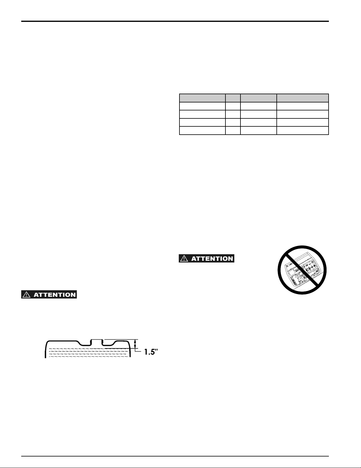
22
Français
INSPECTION INITIALE
Une fois que vous aurez reçu votre ensemble de génératrice,
inspecter le produit afin de vous assurer qu'il est complet et en
bonne condition. Manipuler avec soin et placer dans un endroit
convenable pour l'utilisation ou le remisage.
MISE À LA TERRE
Le générateur doit être relié à la terre pour réduire les risques
de décharge électrique. Pour ce faire, vous aurez besoin d'une
tige de mise à la terre et d'un fil de cuivre conducteur de terre
d'une grosseur appropriée. Enfoncer la tige de mise à la terre
dans le sol, connecter une extrémité du fil de cuivre à la tige et
l'autre extrémité à la prise extérieure de mise à la terre située
sur la génératrice. Ceci n'est qu'une explication générale,
consulter les codes électriques nationaux et locaux pour en
assurer la conformité.
LE GENERATEUR LIEN NEUTRE
Il y a un conducteur permanent entre le générateur (stator
bobinage) et le cadre.
AVANT LE DÉMARRAGE
ESSENCE DU MOTEUR
Utiliser de l'essence sans plomb avec un indice d'octane
minimum de 86. Vérifier la jauge à essence à côté du réservoir
et en ajouter si nécessaire.
• LENTEMENT AJOUTER SANS PLOMB ESSENCE AU
RESERVOIR DE CARBURANT
• NE REMPLISSEZ PAS TROP LE RESERVOIR
• LAISSEZ 1,5 POUCE (38 MM) D’ESPACE DE
RESERVOIR POUR L’EXPANSION DE CARBURANT
Huile à moteur
Le manuel du moteur ou toute autre information fournie par le
manufacturier du moteur remplace les données fournies. La
qualité d'huile adéquate varie selon le climat. La qualité
énumérée dans le tableau est adéquate, mais consulter tout de
même le manuel du moteur pour vérifier. La qualité de l'huile à
utiliser varie selon le climat. Les orifices pour le remplissage
d'huile sont situés de chaque côté du moteur. Le bouchon gris
comporte une tige graduée. Ajouter la quantité suffisante
d'huile et vérifier le niveau à l'aide de la tige graduée. NOTE:
la tige graduée doit être insérée dans l'ouverture sans être
tournée.
BATTERIE DE DÉMARRAGE (Modèles électriques
seulement)
Elle est certifiée 12V-18AH (12V-34AH pour DXGN14000) et
elle est complètement chargée si elle affiche 13.7VDC que
vous pouvez mesurer à l'aide d'un voltmètre.
POSITIONNEMENT
• Placer la génératrice sur une surface plane et solide afin
d'éviter qu'elle coule.
• Gardez les carburants, pétrole et tout autre matériau
inflammable ou combustible à une distance sécuritaire du
groupe électrogène.
• Choisir un endroit bien ventilé et protégé des intempéries.
• Placer la génératrice loin des animaux et des humains.
PENCHER
PEUT CAUSER DU RENVERSEMENT
DE CARBURANT
UTILISATION
Vérifier le niveau d'huile avant chaque utilisation. Ne jamais
faire fonctionner avec une quantité insuffisante d'huile.
Surcharge de la génératrice
Ne pas dépasser la capacité recommandée de la génératrice
lorsque utilisée en continue. Avant de brancher des pièces à la
génératrice, déterminer les besoins totaux en électricité du
produit à connecter. Les besoins de chaque pièce sont
généralement inscrits sur la plaque d'identification du fabricant.
Voici une liste des pièces communément utilisées et leurs
besoins typiques. Utiliser cette liste comme référence
seulement s'il n'y a pas d'autres données.
UTILISATION
INFORMATION GÉNÉRALE
Ce manuel à été préparé pour vous informer sur l'utilisation et l'entretien de ce produit. Étudier attentivement les informations
fournies pour éviter des problèmes reliés à un usage inapproprié ou un mauvais entretien. Vérifier que votre ensemble sera
complet et en bon état dès la réception de votre génératrice.
La génératrice comprend un moteur à 4 temps refroidi à l'air, couplé à un alternateur produisant 125 VAC ou 125/250 VAC, selon
le modèle. La vitesse approximative sans charge est de 3751 tr/min avec une vitesse avec charge d'environ 3600 tr/min, pour la
production d'une fréquence de 60Hz.
MOTEUR HP Capacité Qualité
Honda GX270 8.5 1.16 qt (1.1 l) API SJ SAE 10W-30
Honda GX340 10.7 1.16 qt (1.1 l) API SJ SAE 10W-30
Honda GX390 11.7 1.16 qt (1.1 l) API SJ SAE 10W-30
Honda GX630 20.2 2.1 qt (2.0 l) API SJ SAE 10W-30
0068660
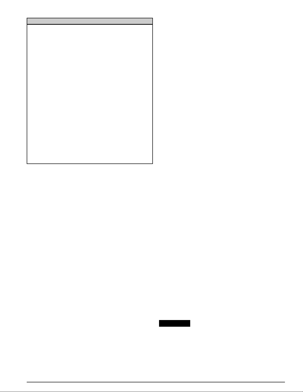
23
0068660Français
NOTE: Plusieurs appareils tels que les scies ou les perceuses
demandent plus de courant qu'indiqué sur la plaque lorsque
surchargés.
DÉMARRER LA GÉNÉRATRICE
Avant de démarrer votre génératrice, assurez-vous d'avoir suivi
toutes les instructions des sections précédentes.
• Vérifier les niveaux d'huile et d'essence.
• Ouvrir la valve d'essence.
• Déplacer le levier de l'" étrangleur " à l'avant en position "
ON ". Note: l'étrangleur n'est pas obligatoire si le moteur
est chaud ou dans des températures ambiantes élevées.
• Tournez l'interrupteur au ralenti-contrôle à "OFF".
DÉMARRAGE MANUEL
• Mettre l'interrupteur ON/OFF du moteur en position ON.
• Tirer le cordon de recul jusqu'à ce qu'une résistance ce
fasse sentir, tirer ensuite fermement. Laisser le cordon
revenir doucement pour ne pas le briser.
• Remettre l'étrangleur à sa position initiale.
DÉMARRAGE ÉLECTRIQUE (DXGN7200)
• Mettre l'interrupteur ON/OFF du moteur en position ON.
• Presser et maintenir l'interrupteur ON/OFF en position de
démarrage jusqu'à ce que le moteur démarre. Note: Si le
moteur ne démarre pas en 5 secondes, attendre 10
secondes et répéter les instructions.
• Remettre l'étrangleur à sa position initiale.
DÉMARRAGE ÉLECTRIQUE (DXGN14000)
• Tournez l'interrupteur sur "START". Après que le moteur
démarre, relâchez l'interrupteur.
• Remettre l'étrangleur à sa position initiale
ATTENTION: Cette génératrice est équipée d'un système de
protection d'huile. Le moteur s'éteint et/ou ne démarre pas
lorsque le niveau d'huile est trop bas pour un usage
sécuritaire.
UTILISATION DE LA GÉNÉRATRICE
Une fois en marche, allouer approximativement 3 minutes au
moteur pour se stabiliser. Vérifier que les disjoncteurs et les
réceptacles (prises femelles) GFCI sont correctes. Tourner le
commutateur de contrôle en position ON si cette fonction doit
être utilisée. Mettre le commutateur de sélecteur de tension au
mode approprié, 120V ou 120/240V. Voir les guides ci-dessous
pour plus d'information sur le contrôle et les fonctions
(dispositifs) de sélecteur de tension.
GUIDE DU CONTRÔLE DE RALENTI (modèles applicables)
Le système de contrôle automatique de ralenti est disponible
sur certaines génératrices. Cette fonction permet au moteur de
ralentir automatiquement lorsqu'il n'y a pas de charge
demandée à la génératrice ce qui économise l'essence,
diminue l'usure et le bruit. Il y a un commutateur ON-OFF sur
le panneau de contrôle qui active ou désactive cette fonction.
Sur la position ON, le moteur ralentit s'il ne détecte pas de
charge supérieure à 40 watts. Le moteur retournera à sa
vitesse normale dès qu'une charge de 350 watts ou plus sera
appliquée. Lorsque vous utilisez des charges de moins de 50
watts, comme dans le cas d'un usage de secours dans une
maison cette option devra être désactivée. Cette option devra
être fermée lorsque vous démarrez ou arrêtez la génératrice et
allumée lorsqu'il y a des périodes d'inactivité de la génératrice.
Modèle DXGN14000: Un 12V batterie être installée pour le
commande de ralenti pour fonctionner.
GUIDE DE SÉLECTION DU VOLTAGE (modèles
applicables)
Le commutateur de sélection de voltage permet à la
génératrice de produire 120 volts seul ou 120/240
simultanément. Seuls les réceptacles 120V doivent être utilisés
avec le commutateur en position 120V. Tout le courant de la
génératrice est disponible à 120V mais la sortie 240V ne l'est
pas. Tous les réceptacles sont disponibles en position 120/240
mais seulement la moitié du débit est disponible dans chaque
réceptacle de 120V. Le plein débit peut être tiré de la
génératrice à partir des réceptacles 240V. Le commutateur doit
toujours être laissé en position 120V lorsque le 240V n'est pas
nécessaire. Ceci balance mieux la charge de la génératrice.
ARRÊT DE LA GÉNÉRATRICE
Débrancher tous les appareils et laisser la génératrice
fonctionner sans charge pendant quelques minutes. Tourner le
commutateur du moteur ON/OFF ou le commutateur clé dans
la position OFF. Tourner la valve d'essence au OFF la position.
Ne jamais utiliser l'étrangleur pour arrêter le
moteur.
Pièce Watts en marche
Air conditionné (12000 Btu) (*) . . . . . . . . . . . . . . . . . . .1750
Compresseur à air (1/2 HP) (*) . . . . . . . . . . . . . . . . . . .1400
Compresseur à air (3/4 HP) (*) . . . . . . . . . . . . . . . . . . .1800
Compresseur à air (1 HP) (*) . . . . . . . . . . . . . . . . . . . .2000
Chargeur de batterie (25A) . . . . . . . . . . . . . . . . . . . . . . .600
Sableuse à ruban (3" ruban) . . . . . . . . . . . . . . . . . . . . .1000
Scie circulaire (7 1/4") . . . . . . . . . . . . . . . . . . . . . . 825-1050
Cafetière . . . . . . . . . . . . . . . . . . . . . . . . . . . . . . . . . 900-1100
Taille bordure (gazon) . . . . . . . . . . . . . . . . . . . . . . . . . . . .550
Ventilateur de fournaise (1/3 HP) (*) . . . . . . . . . . . . . . .1200
Réchaud (simple) . . . . . . . . . . . . . . . . . . . . . . . . . . . . . .1500
Clef à impact . . . . . . . . . . . . . . . . . . . . . . . . . . . . . . . . . . .600
Ampoule . . . . . . . . . . . . . . . . . . . . . . .Classement d'ampoule
Marteau pneumatique . . . . . . . . . . . . . . . . . . . . . . . . . . .1200
Micro-onde . . . . . . . . . . . . . . . . . . . . . . . . . . . . . . . . . . . .750
Fusil à peinture (1/3 HP) (*) . . . . . . . . . . . . . . . . . . . . . .650
Fusil à peinture, pulvérisateur manuel . . . . . . . . . . . . . . .175
Radio . . . . . . . . . . . . . . . . . . . . . . . . . . . . . . . . . . . . . .50-200
Réfrigérateur (*) . . . . . . . . . . . . . . . . . . . . . . . . . . . . . . . .600
Banc de scie (10") (*) . . . . . . . . . . . . . . . . . . . . . . . . . . .2000
Télévision . . . . . . . . . . . . . . . . . . . . . . . . . . . . . . . . .250-550
Taille haies . . . . . . . . . . . . . . . . . . . . . . . . . . . . . . . . . . . .500
Note: (*) Les pièces ont besoin de 3 fois le wattage inscrit
lors du démarrage.
GUIDE GÉNÉRAL DES WATTS
AVIS :
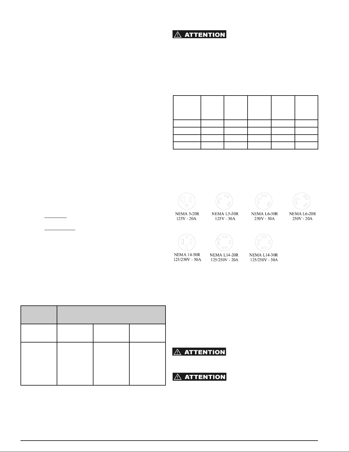
24
Français
USAGE DE LA GÉNÉRATRICE
QU'EST-CE QU'UNE GÉNÉRATRICE?
Une génératrice est principalement un moteur à essence ou au
diesel couplé à un alternateur pour produire de l'électricité.
C'est une bonne alternative d'énergie lorsqu'il y a des pannes
d'électricité ou encore lorsque vous êtes dans un endroit
éloigné où l'électricité n'est pas disponible. Les génératrices
sont indispensables pour les gens comme les agriculteurs ou
les entrepreneurs qui ont souvent besoin d'une source portable
d'électricité. Elles sont également très utiles pour un usage
récréatif.
CHOISIR UNE GÉNÉRATRICE
Le choix de la bonne génératrice est important. Une
génératrice trop petite pour alimenter vos équipements ne
pourra pas les faire fonctionner tous, alors qu'une génératrice
trop grosse coûte plus cher et représente une perte d'argent
lorsqu'elle ne fonctionne pas à son plein potentiel. La grosseur
de génératrice adéquate peut être déterminée en additionnant
les watts de chaque article à employer simultanément avec les
watts nécessaires à l'allumage. Sélectionner une génératrice
avec un taux continu qui dépasse votre total de 20% afin de
permettre une expansion éventuelle. Voir le tableau de la
section intitulée " Surcharge de la génératrice " pour les
normes d'équipements fréquemment utilisées.
WATTS CONTINU versus WATTS MAXIMUM
Les watts nominaux
ou continus sont le nombre de watts
nécessaires à un équipement lorsqu'il fonctionne.
Les watts de surtension
ou maximums sont le nombre de watts
requis pour démarrer un équipement.
Cette information est habituellement inscrite sur la plaque du
manufacturier. Si les watts ne sont pas inscrits, ils peuvent être
calculés en utilisant la formule suivante: watts = ampères x
volts.
RALLONGE ÉLECTRIQUE
Une rallonge électrique devrait toujours être en bonne
condition, sans dommages aux fils et au recouvrement. Ne
jamais plonger une rallonge dans l'eau. La grosseur adéquate
pour une rallonge peut être déterminée par le tableau suivant.
CHARGER VOTRE GÉNÉRATRICE
S.V.P. réviser les réceptacle à courant de votre génératrice à
l'aide des informations contenues dans la section " réceptacle
". Les taux du disjoncteur et de la génératrice conduisent la
capacité réelle qui peut être demandée pour chaque
réceptacle. Les taux montrés dans le tableau représentent le
maximum disponible pour chaque réceptacle.
NE PAS DÉPASSER LE TAUX DE
CHAQUE RÉCEPTACLE INDIVIDUEL TEL QUE DÉMONTRÉ
DANS LE TABLEAU CI-DESSOUS. NE PAS DÉPASSER LE
TAUX MAXIMUM DE LA GÉNÉRATRICE, TEL QUE
DÉMONTRÉ DANS LE TABLEAU 2, PERFORMANCE ET
SPÉCIFICATIONS. Toutes les génératrices sont équipées d'un
disjoncteur thermo-magnétique principal ainsi qu'un disjoncteur
" PRESSER POUR REDÉMARRER ".
TABLEAU DU TAUX D'AMPÉRAGE
*Avec le sélecteur de voltage réglé à 120V.
LIMITE DU MOTEUR SUR LA PERFORMANCE DE LA
GÉNÉRATRICE
Le niveau de la génératrice est évalué à une température de
60 F (20C) au niveau de la mer. L'utilisation de votre
génératrice à des températures au-dessus de 60 F (20C) ou
au-dessus du niveau de la mer résultera en une basse de la
tension électrique. La tension électrique doit-être dégrevé de
1% pour chaque 10 F au-dessus de 60 F et de 3 ½ % pour
chaque 1000 pieds au-dessus du niveau de la mer.
NETTOYAGE DE LA GÉNÉRATRICE
TOUJOURS ÉTEINDRE LA
GÉNÉRATRICE ET ATTENDRE QU'ELLE REFROIDISSE
AVANT DE LA NETTOYER.
NE PAS UTILISER DE L'EAU À
HAUTE PRESSION OU UN BOYAU DE JARDIN POUR
NETTOYER VOTRE GÉNÉRATRICE. L'INTRODUCTION
D'EAU À L'INTÉRIEUR DE LA GÉNÉRATRICE PEUT
PROVOQUER UN COURT-CIRCUIT, DES DOMMAGES À LA
GÉNÉRATRICE OU DES BLESSURES PHYSIQUES.
Model NEMA
5-20R
125V
GFCI
NEMA
L5-30R
125V
Twistlock
NEMA
L14-20R
125/250V
Twistlock
NEMA
L14-30R
125/250V
Twistlock
NEMA
14-50R
125/250V
DXGN4500 20 Amps 30 Amps* 20 Amps* NA NA
DXGN6000 20 Amps 30 Amps* NA 30 Amps* NA
DXGN7200 20 Amps 30 Amps NA 30 Amps NA
DXGN14000
20 Amps NA NA 30 Amps 50 Amps
Charge
Continue
Jauge Minimum (AWG)
Ampères 0-50 Pieds 50-100
Pieds
100-150
Pieds
20
25
30
35
40
50
12
12
10
10
8
6
10
10
8
8
6
4
8
6
6
4
2
2
DÉTAILS DES RÉCEPTACLES (PRISE FEMELLE)
Les réceptacles montrés dans cette section sont uniquement à
titre de référence. Tous les réceptacles ne sont pas disponibles
sur toutes les génératrices.
0068660

25
0068660Français
• De l'air compressé (max.25 psi) peut être utilisé pour
enlever la saleté de votre génératrice. NE PAS
ENVOYER D'AIR DIRECTEMENT DANS AUCUNE
OUVERTURE DE LA GÉNÉRATRICE OU DU MOTEUR.
• Utiliser un linge humide pour nettoyer les surfaces
extérieures.
• Utiliser une brosse à poil doux pour nettoyer la saleté
tenace et les dépôts d'huile ou de graisse.
• Ne jamais insérer des chiffons, des outils ou tout autre
objet à l'intérieur des ouvertures de la génératrice ou du
moteur.
RÈGLES GÉNÉRALES D'ENTRETIEN
LES VAPEURS D'ESSENCE SONT
INFLAMMABLES. NE PAS RANGER VOTRE GÉNÉRATRICE
DANS UN ENDROIT SE TROUVANT À L'INTÉRIEUR OU
DANS UN ENDROIT TRÈS PEU VENTILÉ. LES VAPEURS
D'ESSENCE PEUVENT S'ENFLAMMER À PROXIMITÉ
D'UNE FLAMME VIVE, D'UN PILOTE, D'UNE SÉCHEUSE,
D'UN CHAUFFE-EAU, ETC.
Votre génératrice devrait être démarrée et utilisée pour
plusieurs minutes au moins une fois tous les 30 jours. Si le
groupe électrogène n'est pas utilisé ou qu'il est remisé
pendant plus d’un mois, procéder comme suit:
1. Remettre de l’huile jusqu’au repère supérieur.
2. Faites fonctionner la génératrice, puis fermez le robinet
d'arrêt de carburant et laissez l'appareil fonctionner jusqu'à
l'arrêt du moteur.
3. Placez l’interrupteur du moteur en position “OFF”.
(Tournez l’interrupteur à clé à “ARRÊT” pour les modèle
DXGN14000.)
4. Quand l'appareil est refroidi, purgez l'essence du réservoir
de carburant, de la conduite de carburant et du
carburateur.
5. Mettre environ une cuillerée à café d’huile pour moteur
dans l’orifice des bougies, tirer sur le lanceur à plusieurs
reprises et remettre la bougie en place. Ensuite, tirer sur
le lanceur jusqu’à ce que le piston soit en position de
compression et le laisser dans cette position. Ceci ferme
les soupapes d’admission et d’échappement afin
d’empêcher l’intérieur du cylindre de rouiller.
6. Couvrir l'appareil et l'entreposer dans un endroit propre,
sec et bien aéré, loin de toute source de flamme ou
d’étincelles.
Il est recommandé d'utiliser en tout temps
le stabilisateur de carburant, ce qui permettra de réduire la
formation de dépôts de gomme dans le carburant lors de
son entreposage. On peut ajouter le stabilisateur à
l'essence en le versant soit dans le réservoir de carburant,
soit dans un récipient d'entreposage.
ENTRETIEN GÉNÉRAL
Un entretien adéquat est nécessaire pour prolonger la durée de vie du moteur et maintenir la garantie. Les tableaux
suivants fournissent des spécifications sur le moteur ainsi qu'un calendrier d'entretien. Noter que le modèle de
génératrice fait référence au modèle du moteur. Le manuel du moteur est fourni avec chaque appareil et il fournit
également les informations d'entretien générales ainsi que des informations sur les problèmes techniques. Si les
informations contenues dans ce manuel diffèrent de celles fournies par le manufacturier du moteur, vous référer à
ce dernier. Le manuel d'entretien complet du moteur est disponible chez : American Honda Motor Co., 4900
Marconi Drive, Alpharetta, GA 30005-8847, (800) 910-1293.
AVIS :
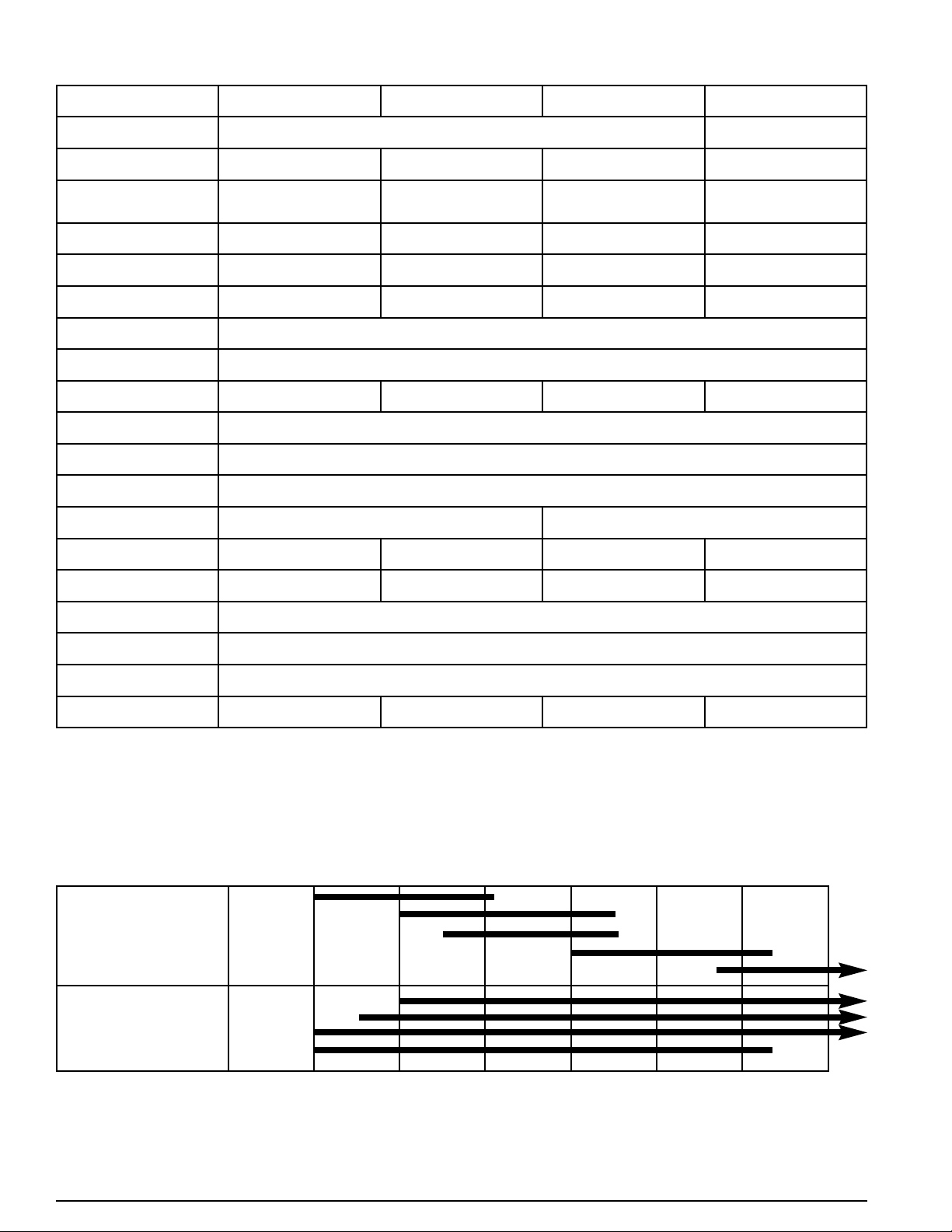
26
Français
SPÉCIFICATIONS DU MOTEUR ET CAPACITÉS
SÉLECTION D'HUILE
Le choix d'une bonne huile ainsi que du bon niveau d'huile sont primordial pour atteindre une plus grande longévité du moteur.
Utiliser une huile à moteur haute en détersif de première qualité certifiée de classe SJ qui devrait être inscrit sur le contenant.
SAE 10W-30 est recommandé pour un usage général à toute température. Vous servir du tableau ci-contre pour sélectionner la
bonne huile pour la température de votre région.
Viscosité -30C/-22F -20C/-4F -10C/14F 0C/32F 10C/50F 20C/68F 30C/86F 40C/104F
Simple 10W
20W
20
30
40
Multi 20W-40, 20W-50
15W-40, 15W-50
10W-40
10W-30
Modèle GX270 (DXGN4500) GX340 (DXGN6000) GX390 (DXGN7200) GX630 (DXGN14000)
Type 4-stroke, overhead vale single cylinder, inclined 25°
4-stroke, overhead valve, V-
Twin
Écart 270cc (16.5 cu in) 389cc (23.7 cu in) 389cc (23.7 cu in) 688cc (42.0 cu in)
Calibre et
empattement
73 x 58 mm
(2.9 x 2.3 in)
88 x 64 mm
(3.5 x 2.5 in)
88 x 64 mm
(3.5 x 2.5 in)
78 x 72 mm
(3.1 x 2.8 in)
Puissance nette 8.5 hp @3600rpm 10.7 hp @3600rpm 11.7 hp @3600rpm 20.2hp @3600rpm
Moment de torsion net 14.1ft-lb @2500rpm 19.5ft-lb @2500rpm 19.5ft-lb @2500rpm 35.1ft-lb @2500rpm
Ratio compression
8.5 : 1 8.2 : 1 8.2 : 1 9.3 : 1
Système de
refroidissement
Forced-air
Système d'ignition
Transistorized magneto
Synchro d'ignition
25° B.T.D.C. (fixed)
Bougies BPR6ES (NGK), W20EPR-U (Nippondenso)
Carburateur Horizontal type, butterfly valve
Filtre à air Dual element type
Système de
lubrification
Splash Forced Oil
Capacité d'huile 1.1l (1.16 US qt) 1.1l (1.16 US qt) 1.1l (1.16 US qt) 2.0 l (2.1 US qt)
Système de
démarrage
Recoil Recoil Recoil/Electric Electric
Système d'arrêt Ignition primary circuit ground
Type de combustible
Unleaded gasoline (86 pump octane)
Rotation de l'arbre
(PTO)
Counterclockwise (from PTO side)
Poids sec 25.0 kg (55.1 lb) 31.5 kg (69 lb) 31.5 kg (69 lb) 44.0 kg (96.8 lb)
0068660
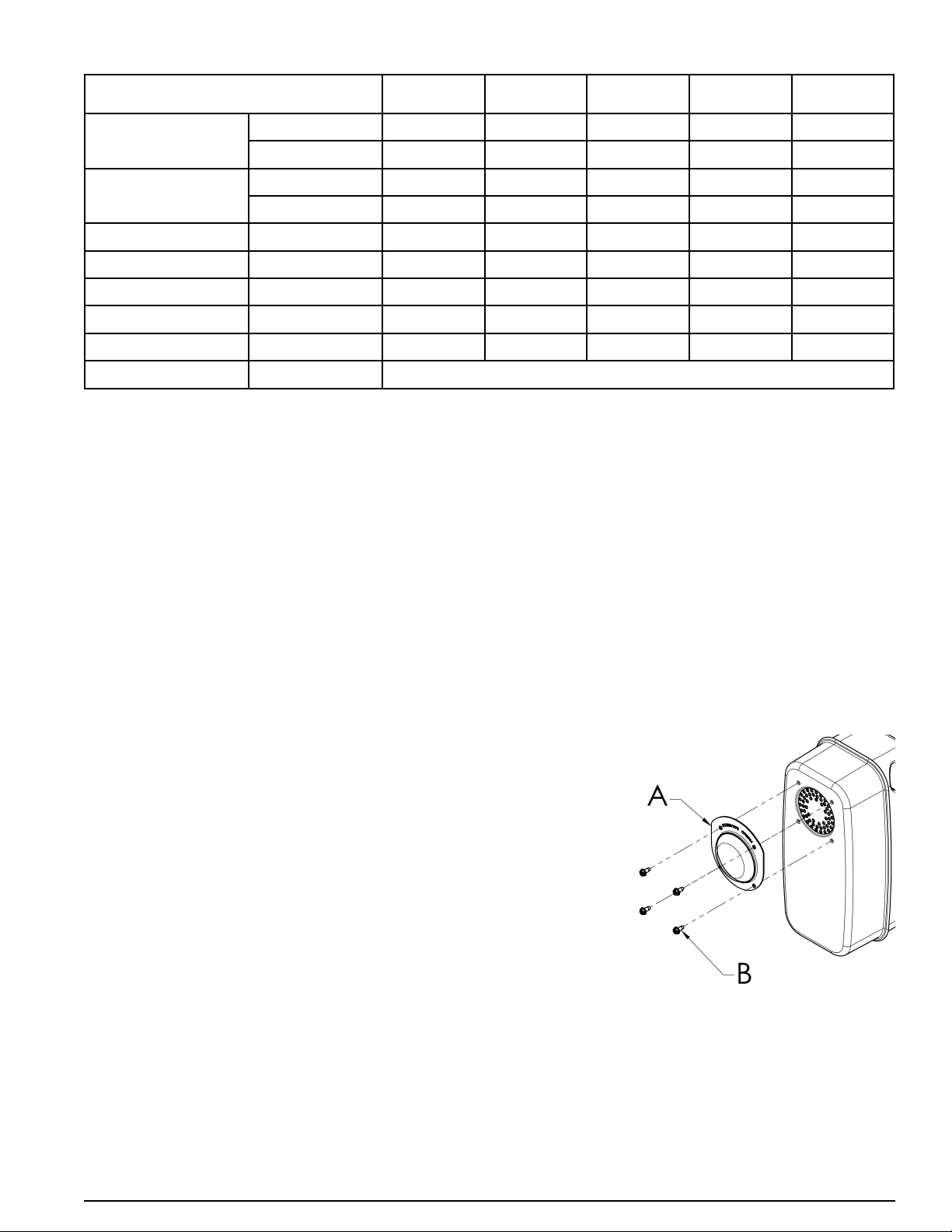
27
0068660Français
HORAIRE D'ENTRETIEN DU MOTEUR
Notes:
(1) Faire l'entretien plus souvent dans les endroits poussiéreux.
(2) L'entretien devrait être fait par un marchand autorisé à moins que le propriétaire possède les outils requis et des
compétences en mécanique. Voir le manuel du moteur.
INSPECTION QUOTIDIENNE
1. Cordon de démarrage 5. Inspecter le système de refroidissement pour la propreté
2. Niveau d'huile moteur 6. Écouter pour des sons anormaux
3. Vérifier les fuites d'huile et d'essence 7. Regarder pour des vibrations anormales
4. Inspecter les câbles à bougies
PARE-ÉTINCELLES
Le pare-étincelles doit être entretenu toutes les 100 heures pour pouvoir contineur à fonctionner de la manière
prévue.
Si le moteur vient de tourner, le silencieux sera chaud. Le laisser se refroidir avant de contrôler le pare-étincelles.
DXGN4500, DXGN6000, et DXGN7200
Nettoyer et inspecter les pare-étincelles comme suit :
1. Enlever la quatre vis (B) et tamis de pare-étincelles (A) du
silencieux.
2. Utiliser une brosse pour retirer la calamine du tamis du
pare-étincelles. Veiller à ne pas endommager le tamis.
3. Le pare-étincelles ne doit pas être cassé ou troué.
Remplacer le pare-étincelles s’il est endommagé.
4. Fixez l'écran pare-étincelles (A) au silencieux en alignant
les trous de l'écran avec les trous percés dans le
silencieux. Insérez les quatre vis (B) dans les trous et
serrez solidement.
DXGN14000
Voir des instructions fournies avec la Kit de Pare-étincelles.
Article
Chaque
utilisation
1er mois ou
20 heures
3 mois ou
50 heures
6 mois ou
100 heures
Chaque année ou
300 heures
Huile
Vérifié X
Changé X X
Nettoyeur à air
Vérifié X
Nettoyé X (1)
Boîte à sédiments Nettoyé X
Bougies Vérifié-Nettoyé X
Coupe étincelles Nettoyé X
Valve Vérifié-Ajusté X (2)
Réservoir d'essence Nettoyé X (2)
Ligne d'essence Vérifié Remplacer si nécessaire

28
Français
GUIDE DES FAILLES
0068660
SYMPTÔMES CAUSES PROBABLES CORRECTION
LE MOTEUR NE DÉMARRE PAS 1. Niveau d'huile trop bas.
2. Pas d'essence ou valve fermé.
3. Démarre avec commutateur à OFF.
4. Système d'essence bloqué ou qui
fuie.
5. Filtre à air obstrué.
6. Génératrice sous tension avant le
démarrage
1. Ajouter de l'huile
2. Ajouter de l'essence ou ouvrir la
valve.
3. Mettre le commutateur à On.
4. Réparer le système d'arrivée
d'essence.
5. Nettoyer ou remplacer le filtre à air.
6. Débrancher la charge.
IL N'Y A PAS DE COURANT 1. le disjoncteur est sauté.
2. Réceptacle GFCI sauté.
3. disjoncteur défectueux.
4. réceptacle défectueux.
5. Condensateur de l'alternateur
défectueux.
6. diodes de l'alternateur défectueux
7. défauts dans le circuit de l'alternateur
1. Remettre disjoncteur.
2. Remettre GFCI réceptacle.
3. Remplacer disjoncteur
4. Remplacer réceptacle.
5. Remplacer Condensateur.
6. Remplacer diodes.
7. Réparer or remplacer l'alternateur.
MACHINE BRUYANTE 1. Coussinet défectueux.
2. Système d'échappement défectueux.
3. Pièces vibrantes ou bruyantes.
1. Remplacer coussinet.
2. Réparer ou remplacer.
3. Réparer pièces vibrantes ou
bruyantes.
SURCHAUFFE 1. Ventilation openings blocked.
2. Overload.
3. Ambient temperature too high.
1. Clear ventilation openings.
2. Verify load levels.
3. Provide better ventilation for
cooling.
LE DISJONCTEUR SAUTE 1. Circuit surchargé.
2. Équipements ou câbles défectueux.
3. Disjoncteur défectueux.
1. Réduire la charge
2. Vérifier, réparer ou remplacer.
3. Remplacer le disjoncteur.
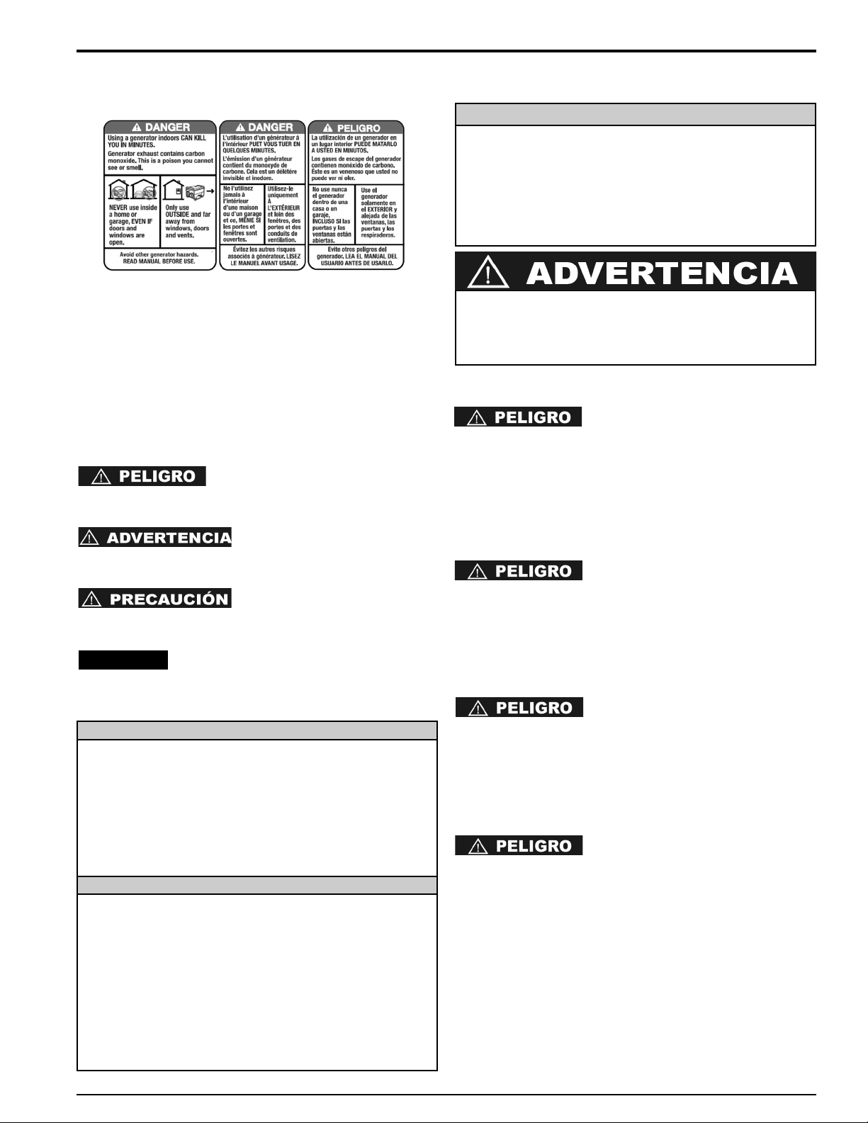
29
Español
LINEAMIENTOS DE SEGURIDAD Y DEFINICIONES
Este manual de instrucciones contiene información importante
que usted debe saber y comprender de manera que pueda
aplicar y operar su generador de manera correcta, segura y
eficiente. Todos los operadores, usuarios y propietarios
subsiguientes de este generador deben leer y comprender
todas las instrucciones antes de operar el generador. Guarde
estas instrucciones para referencia en el futuro.
Para ayudarle a reconocer información importante para
proteger SU SEGURIDAD y EVITAR PROBLEMAS CON EL
EQUIPO, utilizaremos los símbolos siguientes.
Indica una situación de peligro
inminente que, si no se evita, provocará la muerte o lesiones
graves.
Indica una situación de peligro
potencial que, si no se evita, podría provocar la muerte o
lesiones graves
Indica una situación de peligro
potencial que, si no se evita, puede provocar lesiones leves o
moderadas.
Se refiere a una práctica no relacionada a
lesiones corporales que de no evitarse puede resultar en
daños a la propiedad.
REGLAS DE SEGURIDAD
RIESGO DE ASFIXIA
NO OPERE ESTE GENERADOR EN
UNA AREA CERRADA. LOS GASES DE ESCAPE DE ESTE
GENERADOR EMITEN “MORTAL’ MONOXIDO DE
CARBONO. EXPONERSE AL MONOXIDO DE CARBONO
PUEDE CAUSAR ENVENENAMIENTO DE MONOXIDO DE
CARBONO, DOLORES DE CABEZA, NAUSEA, SEVERA
ENFERMEDAD O LA MUERTE.
RIESGO DE ELECTROCUCIÓN O SACUDE
ESTE GENERADOR PRODUCE
CORRIENTE ELECTRICAT. POR LO TANTO, LAS GUIAS DE
SEGURIDAD DEBEN DE SEGUIRSE. USO INAPROPIADO
DE ESTE GENERADOR PUEDE RESULTAR EN
ELECTROCUCION, LESIONES OR LA MUERTE. NO OPERE,
HAGA REVISIONES O REPARACIONES A ESTE
GENERADOR A MENOS QUE ESTE COMPLETAMENTE
CALIFICADO PARA HACERLO.
ESTE GENERADOR FUE DISEÑADO
PARA FUNCIONAR EN CONDICIONES SECAS Y SOLO AL
AIRE LIBRE. NUNCA OPERE ESTE GENERADOR EN
LUGARES CERRADOS. NUNCA OPERE ESTE
GENERADOR LLUVIA, NIEVE, AGUANIEVE,
CONDICIONES MOJADS EN GENERAL. DAÑOS AL
GENERADOR, LESIONES FISICAS, O LA MUERTE PUEDEN
RESULTAR DE ELECTROCUCION.
SI ESTE GENERADOR ES
CONECTADO A UNA COMPLEXION, HOGAR, NEGOCIO, U
OTRO CIRCUITO ELECTRICO NORMALMENTE
ALIMENTADO POR EL SUMINISTRO DE LA RED, PASOS
DEBEN DE TOMARSE PARA ASEGURAR LA POTENCIA DEL
GENERADOR Y EL SUMINISTRO DE LA RED ESTÁN
POSITIVAMENTE AISLADOS. TIPICAMENTE ESTO ES
LLEVADO A CABO A TRAVES DEL USO DE UN CUADRO DE
CONMUTACIÓN INSTALADO APROPIADAMENTE. FALTA DE
AISLAMIENTO DEL SISTEMA ELECTRICO DE LA RED Y EL
GENERADOR RESULTARA EN DAÑOS AL GENERADOR Y
PUEDE RESULTAR EN LESIONES FISICAS O LA MUERTE A
TRABAJADORES DE LA RED DEBIDO AL RETORNO DE LA
ELECTRICIDAD.
SPANISH INSTRUCTIONS
SEGURIDAD
Cierto Estados y Jurisdicciones requieren que el equipo
manejado por motor este equipado con silenciadores con
atrapa chispas. Dependiendo en el Modelo de generador,
silenciadores con atrapa chispas pueden o no ser
equipados. Si silenciadores con atrapa chispas son
requeridos para su localidad y su silenciador no es atrapa
chispas, comuníquese con su representante local para
instrucciones para un retrofit.
SILENCIADOR CON ATRAPACHISPAS
El sistema de control de emisiones de escape para este
generador cumple con los principios fijados en California Air
Resources Board (CARB) y la Environmental Protection
Agency (EPA). Los respectivos fabricantes des motores
administran las garantías del sistema de emisiones de
escape. Consulte a la documentación del motor para
información sobre la garantía.
SISTEMA DE CONTROL DE EMISIONES DE ESCAPE
Si el producto se va a utilizar cerca de materiales inflamables
como son cosechas agrícolas, bosques, arbustos, pastos, etc.,
debe entonces instalarse un apagachispas adecuado. Esto es
obligatorio en el estado de California, de acuerdo con las
secciones de estatutos 13005(b), 4442 y 4443. Los
apagachispas son también obligatorios en algunas tierras del
Servicio Forestal de los EE.UU. y quizá también según otros
estatutos u ordenanzas legales. Existen apagachispas de uso
aprobado en nuestro distribuidors. También puede encargarse
a D
EWALT Industrial Tool Co., 701 East Joppa Road, Baltimore,
MD 21286, EE.UU., teléfono 1-888-431-6871.
APAGACHISPAS
0068660
AVISO:
El exhaust del motor de este producto contiene
químicos conocidos por el Estado de California como
causantes de cáncer, defectos al nacer, u otros daños
reproductivos.
30
0068660Español
PARA EVITAR LA
RETRO-ALIMENTACIÓN HACIA LOS SISTEMAS DE
SUMINISTRO ELÉCTRICO, SE REQUIERE EL AISLAMIENTO
DEL SISTEMA ELÉCTRICO RESIDENCIAL. ANTES DE
REALIZAR LA CONEXIÓN DEL GENERADOR AL SISTEMA
ELÉCTRICO RESIDENCIAL, APAGUE EL INTERRUPTOR
PRINCIPAL. ANTES DE HACER LAS CONEXIONES
PERMANENTES, DEBE INSTALARSE UN INTERRUPTOR
DE TRANSFERENCIA DE DOS VÍAS. PARA EVITAR LA
ELECTROCUCIÓN O DAÑOS A LA PROPIEDAD, SÓLO
DEBE SER UN ELECTRICISTA ENTRENADO EL QUE
CONECTE EL GENERADOR AL SISTEMA ELÉCTRICO
RESIDENCIAL. LAS LEYES DE CALIFORNIA REQUIEREN
EL AISLAMIENTO DEL SISTEMA ELÉCTRICO RESIDENCIAL
ANTES DE CONECTAR UN GENERADOR A LOS SISTEMAS
ELÉCTRICOS RESIDENCIALES.
SIEMPRE SIGA LOS CÓDIGOS Y REGULACIONES
LOCALES QUE SE APLICAN A LA INSTALACIÓN DE
CUALQUIER ELEMENTO QUE TENGA RELACIÓN CON
ESTE PRODUCTO.
1. NFPA 70 - Código Nacional de Electricidad.
2. NFPA 37 - Estándar para la instalación y uso de
motores estacionarios de combustible.
3. Manual de cableado agrícola de la energía eléctrica en
posición auxiliar para granjas.
NO MODIFIQUE O USE
INDEBIDAMENTE SU GENERADOR. FUNCIONAMIENTO
DEL GENERADOR OTRO QUE EL INDICADO PUEDE
RESULTAR EN DAÑOS AL GENERADOR, LESIONES
FISICAS, O LA MUERTE PUEDEN RESULTAR DE
ELECTROCUCION
NUNCA TOQUE UN RECEPTACULO O
UN CABLE PELADO. ELECTROCUCION O UN IMPACTO
PUEDE RESULTAR DEBIDO A ESTO.
RIESGO DE INCENDIO O EXPLOSIÓN
SIEMPRE ASEGURESE QUE SE
MANTENGAN POR LO MENOS 6 PIES DE DESPEJE EN
TODOS LOS LADOS DEL GENERADOR DURANTE EL
FUNCIONAMIENTO DEL MISMO. PUEDE CAUSAR DAÑOS
AL GENERADOR Y POTENCIALMENTE CONDUCIR A
INCENDIOS, LA FALTA DE MANTENER DESPEJE
APROPIADO.
GASOLINA ES MUY INFLAMABLE
Y SUS VAPORES SON EXPLOSIVOS. FALTA DE MANEJO
APROPIADO PUEDE RESULTAR EN UNA EXPLOSION O
INCENDIO. NO PERMITA FUMAR DENTRO DE 50FT DEL
GENERADOR.
NUNCA VUELVA A LLENAR UN
GENERADOR CALIENTE CON COMBUSTIBLE. NUNCA
VUELVA A LLENAR UN GENERADOR MIENTRAS ESTE
FUNCIONANDO. DERRAME SOBRE LEL MOTOR O
GENERADOR PUEDE RESULTAR EN UN EXPLOSION O
INCENDIO. SIEMPRE DEJE QUE EL GENERADOR SE
ENFRIE ANTES DE VOLVER A LLENARLO.
NUNCA GUARDE ESTE
GENERADOR EN CUALQUIER LUGAR DONDE GASES DE
GASOLINA PUEDAN ENTRAR EN CONTACTO
POTENCIALMENTE CON CHISPAS, UNA LUZ DE PILOTO O
UNA LLAMA ABIERTA. ALMACENAMIENTO INAPROPIADO
DE ESTE GENERADOR PUEDE RESULTAR EN UN
EXPLOSION O INCENDIO.
INSPECCIONE LOS
ATRAPACHISPAS PERIODICAMENTE. ATRAPACHISPAS
SON REQUERIDOS EN UNAS AREAS Y REDUCEN EL
RIESGO DE FUEGO DE CHISPAS EMITIDAS DEL ESCAPE.
NO OPERE ESTE GENERADOR
SI LA TEMPERATURA DEL AMBIENTE EXCEDE 104ºF/40ºC.
NO EXCEDA LA CAPACIDAD
INDICADA DEL GENERADOR. EL TOTAL DE CARGAS
ELECTRICAS EN CADA ENCHUFE DEBEN SUMARSE PARA
DETERMINAR EL TOTAL DE CARGA ELECTRICA. EL TOTAL
DE CARGA ELECTRICA NO DEBE EXCEDER EL TOTAL DE
LA CAPACIDAD INDICADA DEL GENERADOR. SI EL
APARATO CONDUCIDO NO LISTA LA POTENCIA EN
VATIOS, PERO SOLO EN AMPERIOS, LA POTENCIA EN
VATIOS PUEDE SER DETERMINADA MULTIPLICANDO LOS
AMPERIOS POR EL VOLTAJE (VATIOS = AMPERIOS X
VOLTIOS).
SEGURIDAD GENERAL
Siempre siga lo códigos Nacionales y Locales relacionados
con generadores. Todos los códigos Nacionales y Locales
reemplazan reglas o información proporcionada en este
manual.
CONSULTE SUS CODIGOS
LOCALES Y NACIONALES PARA DETERMINAR
REQUISITOS DE PUESTA A TIERRA ASÍ COMO ESTO
PUEDE VARIAR POR APPLICACION. EL GENERADOR ES
PUESTO A TIERRA INTERNAMENTE NEUTRAL A LA
MONTURA. DONDE LAS APPLICACIONES REQUIERAN
PUESTA A TIERRA EXTERNA, UNA CONEXIÓN DEBE
HACERSE DEL GENERADOR A UN PUNTO DE TIERRA
SÓLIDO. UN CABLE CONTINUO DE COBRE, LIBRE DE
EMPALMES NO MAS PEQUEÑO DE 6 AWG, DEBE SER
USADO PARA EL CONDUCTOR.
• Cuando mueva o transporte este generador, tome
precauciones adecuadas para evitar derrames de
combustible. Siempre use sentido común cuando levante
este generador. Un adecuado numero de personas y
métodos adecuados para levantar deben ser usados.
• No cubra el generador mientras este en funcionamiento o
inmediatamente después de haberlo apagado. Siempre
permita un tiempo para enfriar antes de cubrirlo.
• No ponga en funcionamiento este generador a menos
que este en buena condición mecánica y eléctrica.
• Siempre mantenga manos, partes del cuerpo, cabello y
ropa lejos de las piezas que giran en el generador.
• No arranque este generador con aparatos conectados
que estén encendidos. Siempre asegúrese que los
aparatos estén desconectados o si están conectados que
estén apagados antes de arrancar el generador.
• Generadores funcionando en sitios de trabajo o
construcción pueden requerir que tengan enchufes GFCI
(Ground Fault Circuit Interrupters).
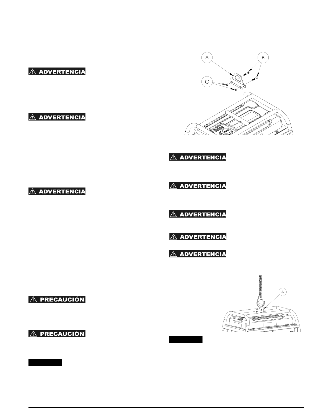
0068660
31
Español
• Use solo cables de extensión puestos a tierra en buena
condición y asegúrese que el tamaño del cable en los
cables de extensión tenga tamaño suficiente para llevar
la potencia de salida del generador.
• Nunca maneje cables de extensión o circuitos eléctricos si
esta parado en agua o áreas mojadas.
RIESGO DE LESIONES CORPORALES
MANTENGA MANOS, PARTES
DEL CUERPO, CABELLO Y ROPA LEJOS DE LAS PIEZAS
“CALIENTES” DEL GENERADOR DURANTE Y DESPUES
DEL FUNCIONAMIENTO. EL EXHAUST SYSTEM, Y EL
GENERADOR EN GENERAL, PUEDEN PERMANCER MUY
CALIENTES AUN DESPUES DE HABER SIDO
APAGADO.
NO MANIPULE CON EL MOTOR
VELOCIDAD GOBERNADA. EL GENERADOR OPERA EN
UNA VELOCIDAD NOMINAL DE 3600 RPM. LOS AUMENTOS
EN la VELOCIDAD SOBRE EL 3600 SUSTANTIVO DE RPM
AUMENTARAN LA OPORTUNIDAD DE HERIDA PERSONAL
DEBIDO A ENFASIS GIRATORIOS EN LOS MIEMBROS QUE
GIRAN. LA OPERACION DEL GENERADOR EN
VELOCIDADES DEBAJO DEL SUSTANTIVO QUE 3600 RPM
PODRIA CAUSAR DAÑO AL GENERADOR O EL APARATO
ACCIONADO DEBIDO A SALIDA BAJA DE VOLTAJE.
SEGURIDAD DE BATERIAS
ALMACENAMIENTO DE
BATERIAS PRODUCE Y EMITE GAS DE HIDROGENO
EXPLOSIVO CUANDO SE CARGA. LA MAS MÍNIMA CHISPA,
LLAMA O CENIZA QUEMANDOCE PUEDE PRENDER
FUEGO A ESTOS GASES Y CAUSAR UNA EXPLOSION
SERIA QUE PUEDE RESULTAR EN CEGUERA U OTRAS
GRAVES LESIONE. USE PROTECCION EN LOS OJOS,
DELANTAL Y GUANTES DE GOMA CUANDO ESTE
TRABAJANDO ALREDEDOR DE BATERIAS CUANDO ESTE
LLEVANDO A CABO SERVICIOS A BATERIAS. EL FLUJO DE
BATERIAS ES ACIDO SULFURICO EXTREMADAMENTE
CAUSTICO, QUE PUEDE CAUSAR SEVERAS
QUEMADURAS. SIEMPRE DESCONECTE EL CABLE
NEGATIVO (-) DE LA BATTERIA ANTES DE LLEVAR A CABO
SERVICIO A UNA BATERIA O ANTES DE LLEVAR A CABO
SERVICIO ELECTRICO A UN GENERADOR O MOTOR.
PROTECCION AMBIENTAL
INSPECCIONE EL SISTEMA DE
ESCAPE REGULARMENTE PARA ASEGURARSE QUE ESTE
FUNCIONANDO APROPIADAMENTE. SISTEMA DE ESCAPE
CON FUGAS PUEDE INCREMENTAR LOS NIVELES DE
RUIDO.
DIRIGE LOS LADOS RUIDOSOS
DEL GENERADOR HACIA ESPACIOS ABIERTOS EVITANDO
RESONANCIA DE PAREDES O COMPLEJOS DE ESTA
MANERA AMPLIFICA EL SONIDO.
NUNCA VACIE OR TIRE ACEITE DE MOTOR
A LA TIERRA O A SUMIDEROS DE AGUAS RESIDUALES
DOMÉSTICOS.
ENSAMBLAJE DEL GANCHO PARA LEVANTAR
Conecte el gancho de elevación (A) al portador con pernos de
3/8 x 2.00" (B) y tuercas nyloc de 3/8 (C) como se muestra en
la ilustración. Apriete los pernos firmemente.
ELEVACIÓN O SUSPENSIÓN DEL GENERADOR
La conexión incorrecta de cables,
cadenas o correas de elevación puede provocar daños a la
propiedad, lesiones graves o la muerte y, además, anula la
garantía del fabricante.
Siempre utilice cables, cadenas o
correas que puedan elevar o suspender un peso de 907 kg
(2000 libras) o más de carga de trabajo para elevar el
generador.
Nunca haga funcionar el generador
mientras está suspendido. Esto podría producir daños a la
propiedad, lesiones graves o la muerte.
NO suspenda otro objeto que no
sea el generador con el gancho para levantar.
Asegúrese de que todos los
sujetadores de la estructura y del gancho para levantar estén
firmes.
Pase el cable, la
cadena o la correa a
través del gancho
para levantar (A),
como se muestra.
Siempre utilice el
gancho para levantar
cuando eleve o
suspenda el
generador.
Asegúrese de que el generador esté una
posición nivelada antes de elevarlo o suspenderlo, con el fin
de evitar daños.
AVISO:
AVISO:
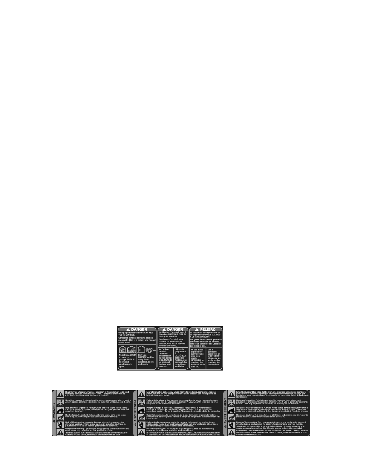
Accesorios
Los accesorios que se recomiendan para la herramienta están disponibles para la compra en su distribuidor local o
en el centro de mantenimiento autorizado. Si necesita ayuda para localizar algún accesorio para su herramienta,
comuníquese con D
EWALT Industrial Tool Co., 701 East Joppa Road, Baltimore, MD 21286, llame al
1-888-431-6871 o visite nuestro sitio Web en www.dewalt.com.
Información de mantenimiento
Para todas las llamadas por mantenimiento, tenga a mano la siguiente información:
Número de modelo _______________________________ Número de serie ________________________________
Fecha y lugar de compra __________________________________
Reparaciones
Para asegurar la SEGURIDAD y la CONFIABILIDAD del producto, las reparaciones, el mantenimiento y los ajustes
deben ser realizados en un centro de mantenimiento de fábrica D
EWALT, un centro de mantenimiento autorizado
DEWALT u otro centro de mantenimiento con personal calificado. Utilice siempre piezas de repuesto idénticas.
Garantía completa de tres años - Estatos Unidos y Canadá
Los generadores para trabajo pesado de DEWalt tienen una garantía de tres (3) años desde la fecha de compra en
Estados Unidos y Canadá. Repararemos, sin cargo, cualquier defecto debido a fallas en los materiales o la mano
de obra. Para obtener información sobre las reparaciones cubiertas por la garantía, visítenos en www.dewalt.com o
llame al 1-888-431-6871. Esta garantía no se extiende a los accesorios o a los daños causados por terceros al
intentar realizar reparaciones. Esta garantía le concede derechos legales específicos; usted goza también de otros
derechos que varían según el estado o provincia.
Garantía completa de un año - México
Los generadores para trabajo pesado de DEWalt tienen una garantía de un (1) año desde la fecha de compra en
México. Repararemos, sin cargo, cualquier defecto debido a fallas en los materiales o la mano de obra. Para
obtener información sobre las reparaciones cubiertas por la garantía, visítenos en www.dewalt.com o llame al
1-888-431-6871. Esta garantía no se extiende a los accesorios o a los daños causados por terceros al intentar
realizar reparaciones. Esta garantía le concede derechos legales específicos; usted goza también de otros derechos
que varían según el estado.
AMÉRICA LATINA (MENOS MÉXICO): Esta garantía no se aplica a los productos que se venden en América
Latina. Para los productos que se venden en América Latina, debe consultar la información de la garantía específica
del país que viene en el empaque, llamar a la compañía local o visitar el sitio Web a fin de obtener esa información.
REEMPLAZO GRATU ITO DE LA ETIQU ETA DE PRECAU CIONES: Si sus etiquetas de advertencia se vuelven
ilegibles o faltan, llame al 1-888-431-6871 para que se le reemplacen gratuitamente.
0068660
32
Español
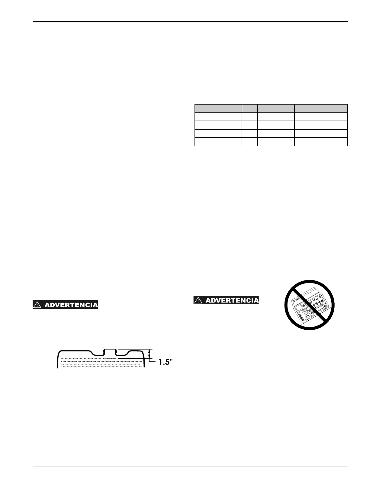
INSPECCIÓN INICIAL
En cuanto reciba su generador, inspeccione el producto para
asegurarse que esta completo y en buena condición.
Manéjese con cuidado y colóquelo en un sitio adecuado para
almacenarlo o ponerlo en función.
PUESTA A TIERRA
El generador debe tener una conexión a tierra para reducir el
riesgo de choque eléctrico. Para hacer esto usted necesitara
una pica de tierra y un cable de cobre de puesta a tierra de
dimensiones apropiadas. Conduzca la pica en la tierra,
conecte una punta del cable de cobre a la pica la otra punta
conexión externa en el generador. Esta es una explicación
general, consulte los códigos Nacionales y Locales para
asegurarse que se cumplan.
EL GENERADOR BONO NEUTRAL
Hay un permanente conductor entre el generador (stator
bobinado) y el marco.
COMENZANDO
COMBUSTIBLE DE MOTOR
Use Gasolina sin plomo con mínimo 86 octanos. Compruebe
el indicador de combustible al lado del la tapa del tanque y
rellénalo cundo sea necesario.
• AGREGUE LENTAMENTE SIN PLOMO GASOLINA AL
TANQUE DE COMBUSTIBLE
• NO LLENE DEMASIADO EL TANQUE
• PERMITA 1,5 PULGADAS (38 MM) DE ESPACIO DE
TANQUE PARA LA EXPANSIÓN DEL COMBUSTIBLE
ACEITE DE MOTOR
El manual del motor u otra información proporcionada por el
fabricante del motor reemplaza los datos dados aquí. Grado
apropiado de aceite varía según el clima. El grado en la lista
de abajo es típicamente un buen grado pero consulte su
manual de motor para verificar el grado apropiado. Los puertos
para rellenar de aceite están localizados en los dos lados del
motor. El tapón gris tiene una varilla integrada para medir el
nivel de aceite. Rellene con la cantidad apropiada de aceite y
cheque el nivel usando la varilla. NOTA: La varilla debe ser
puesta en el agujero pero no debe de atornillarse para
comprobar el nivel de aceite.
BATERÍA DE ARRANQUE (Solo Modelos con Arranque
Eléctrico)
Esta dimensionada a 12V-18AH (12V-34AH para
DXGN14000). La Batería esta totalmente cargada si el voltaje
de 12.84VDC se mide a través de las terminales usando un
DC Voltímetro.
COLOCACIÓN
• Coloque el generador en una superficie plana y sólida
para prevenir que se hunda.
• Mantenga el combustible, aceite u otros materiales
inflamables o combustibles a una distancia segura del
conjunto del generador.
• Seleccione un sitio que este bien ventilado y protegido
del tiempo.
• Coloque el generador con seguridad lejos de gente y
animales.
INCLINAR PUEDE CAUSAR
DERRAME DE COMBUSTIBLE
FUNCIONAMIENTO
Cheque el aceite de motor antes de cada uso. Nunca ponga
en funcionamiento el generador sin suficiente aceite.
SOBRECARGA DEL GENERADOR
No exceda la carga máxima del generador cuando esté en
funcionamiento continuo. Antes de conectar artículos al
generador, determine el total de requisitos eléctricos de los
productos que serán conectados. El requisito de cada artículo
generalmente se da en la placa del nombre del fabricante.
Abajo hay una lista de los artículos usados comúnmente y los
requisitos típicos. Use la lista como una guía solo si no hay
disponible otros datos.
33
Español
FUNCIONAMIENTO
INFORMACIÓN GENERAL
Este manual ha sido preparado para informarlo(a) con el funcionamiento y mantenimiento de este producto. Estudie la
información proporcionada cuidadosamente para evitar problemas asociados con aplicación o mantenimiento inapropiado. En
cuanto reciba su generador, verifique que este completamente en buena condición.
Este generador esta compuesto de un motor de 4 tiempos, refrigerado por aire acoplado directamente a un alternador de 2
polos produciendo ya sea 125VAC o 125/250VAC dependiendo en el modelo. La velocidad sin carga es de aproximadamente
3750 rpm con la velocidad bajo carga siendo aproximadamente a 3600 rpm de esta manera produciendo una frecuencia de
60Hz.
MOTOR HP Capacidad Grado
Honda GX270 8.5 1.16 qt (1.1 l) API SJ SAE 10W-30
Honda GX340 10.7 1.16 qt (1.1 l) API SJ SAE 10W-30
Honda GX390 11.7 1.16 qt (1.1 l) API SJ SAE 10W-30
Honda GX630 20.2 2.1 qt (2.0 l) API SJ SAE 10W-30
0068660
0068660
34
Español
NOTA: Muchos aparatos como sierras o taladros toman mas
corriente que la indicada en la placa del fabricante cuando
esta bajo carga severa.
ARRANQUE DEL GENERADOR
Antes de intentar arrancar el generador, asegúrese que todas
las instrucciones proporcionadas en previas secciones se han
seguido completamente.
• Cheque el nivel de aceite y combustibles.
• Abra la Válvula de combustible.
• Abra la Válvula que esta al frente del motor.
• Prenda el estárter al frente del motor. Nota: el estárter
puede no ser requerido cuando el motor este caliente o en
altas temperaturas ambientales.
• Apague el interruptor de control del ralentí.
ARRANQUE MANUAL
• Mueva el interruptor a posición de ON.
• Lentamente tire del cable de arranque hasta que sienta
resistencia y entonces tire fuerte. Deje que el arranque
rebobine lentamente para evitar daños.
ARRANQUE ELÉCTRICO (DXGN7200)
• Mueva el interruptor a posición de ON.
• Presione y mantenga el interruptor en posición de
arranque hasta que el motor arranque y se suelte. Nota:
Si el motor no arranca después de 5 segundos, pare y
espere 10 segundos y repita es paso.
• Regrese el estárter a la posición original
ARRANQUE ELÉCTRICO (DXGN14000)
• Haga girar la llave a la posición "START". Suelte la llave
después que arranque el motor.
• Regrese el estárter a la posición original
CUIDADO: Este generador esta equipado con un sistema de
protección de aceite. Cuando los niveles de aceite estén muy
bajos para funcionamiento seguro el motor se apagara y / o no
arrancara hasta que se corrijan los niveles de aceite.
EL GENERADOR EN FUNCIONAMIENTO
Una vez encendido, permita que el motor se estabilice por
aproximadamente 3 minutos. Compruebe que los interruptores
y el enchufe GFCI no estén disparados. Encienda el interruptor
del control de ralentí si se utiliza. Ponga el interruptor en el
modo apropiado, ya sea 120V o 120/240V. Vea la guías abajo
para mas información control de ralentí y características del
selector de voltaje.
GUÍA DEL CONTROL DE RALENTÍ (modelos aplicables)
El sistema control de ralentí automático esta disponible en
algunos generadores. Esta característica permite que el motor
frene automáticamente cuando no hay carga en contra del
generador de esta manera ahorrando combustible, reduciendo
el uso y nivel de ruido. Hay un interruptor localizado en el
panel de control que activa o desactiva esta característica.
Cuando está encendido el motor frena después de haber
detectado menos de 40 Vatios. El motor regresara ala veloci-
dad correcta inmediatamente cuando se apliqué una carga de
350 Vatios o más. Para aplicaciones con cargas de menos de
50V o cerca de cargas constantes, como la de un respaldo de
hogar, es mejor que la característica de control de ralentí esté
apagada. Esta característica ha de apagarse antes de arrancar
el generador y encenderse cuando haya periodos extendidos
de inactividad del generador.
Modelo DXGN14000: UNA batería 12V se debe instalar en
la orden para el control en vacío para funcionar.
GUÍA DEL SELECTOR DE VOLTAJE (modelos aplicables)
El selector de voltaje permite que el generador produzca solo
120 Voltios o 120/240 voltios simultáneos. Con el interruptor
en posición del enchufe de 120V puede ser usado. Todo la
potencia del generador esta disponible a 120 voltios pero el
enchufe de 240V no está disponible. En posición de 120/240V
todos los enchufes funcionan, sin embargo solo la mitad de la
potencia del generador es disponible en cualquier enchufe de
120V. La máxima potencia puede ser sacada del generador
del enchufe de 240V. El interruptor debe dejarse en posición
de 120V cuando no se necesiten 240 voltios. Esto estabiliza la
carga en el generador eficazmente.
APAGADO DEL GENERADOR
Desenchufe los aparatos y deje correr el motor sin carga por
unos minutos. Ponga el interruptor del motor o interruptor
clave en posición de Apagado. Gire la válvula de combustible
al OFF posición.
Nunca use el estárter para apagar el motor.
Artículo Consumo en funcionamiento
Aire Acondicionado (12000 Btu) (*) . . . . . . . . . . . . . . . .1750
Compresor de Aire (1/2 hp) (*) . . . . . . . . . . . . . . . . . . .1400
Compresor de Aire (3/4 hp) (*) . . . . . . . . . . . . . . . . . . .1800
Compresor de Aire (1 hp) (*) . . . . . . . . . . . . . . . . . . . . .2000
Cargador de Batería (25A) . . . . . . . . . . . . . . . . . . . . . . . 600
Liador de Banda (3” belt) . . . . . . . . . . . . . . . . . . . . . . .1000
Sierra Circular (7 1/4”) . . . . . . . . . . . . . . . . . . . . . . .825-1050
Cafetera . . . . . . . . . . . . . . . . . . . . . . . . . . . . . . . . .900-1100
Afilador (césped) . . . . . . . . . . . . . . . . . . . . . . . . . . . . . . .550
Abanico de Horno (1/3 hp) (*) . . . . . . . . . . . . . . . . . . . .1200
Plato Caliente (individual) . . . . . . . . . . . . . . . . . . . . . . . .1500
Llave Inglesa . . . . . . . . . . . . . . . . . . . . . . . . . . . . . . . . . 600
Foco . . . . . . . . . . . . . . . . . . . . . . . . . . . . . . . . . . .Bulb rating
Pistola de clavos . . . . . . . . . . . . . . . . . . . . . . . . . . . . . .1200
Microondas . . . . . . . . . . . . . . . . . . . . . . . . . . . . . . . . . . . 750
Esprayadora de Pintura (1/3 hp) (*) . . . . . . . . . . . . . . . . .650
Esprayadora de Pintura, manual-sin aire . . . . . . . . . . . . 175
Radio . . . . . . . . . . . . . . . . . . . . . . . . . . . . . . . . . . . . . .50-200
Refrigerador (*) . . . . . . . . . . . . . . . . . . . . . . . . . . . . . . . . 600
Sierra de Mesa (10”) (*) . . . . . . . . . . . . . . . . . . . . . . . .2000
Televisión . . . . . . . . . . . . . . . . . . . . . . . . . . . . . . . . . .250-550
Cortador de Hierba . . . . . . . . . . . . . . . . . . . . . . . . . . . . . 500
Nota: (*) Artículos permiten por lo menos 3 veces mas
que el voltaje en la lista.starting.
GUÍA GENERAL DE CONSUMOS
AVISO:
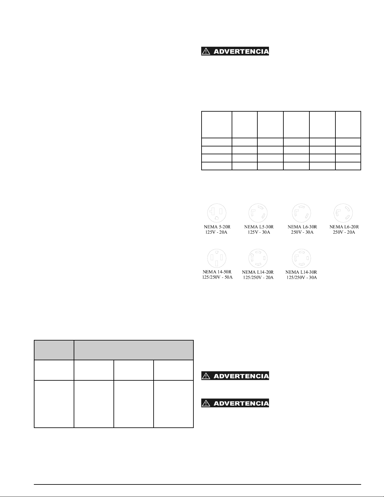
APLICACIÓN DEL GENERADOR
QUE ES UN GENERADOR
Un generador es básicamente un prime mover, típicamente un
motor de gasolina o de diesel, unidos a un alternador para
producir electricidad. Es muy útil como fuente de luz durante
apagones o como fuente principal en localidades remotas
donde no hay luz disponible. Los generadores son
fundamentales para personas como contratistas o agricultores
que son quien siempre necesitan energía portátil. También
son muy convenientes para uso recreativo.
SELECCIONAR UN GENERADOR
Seleccionar el generador apropiado es muy importante. Un
generador que es muy pequeño para su aplicación no hará
funcionar a todo el equipo necesario. Un generador que es
muy grande le costara mas y si no es usado a su potencial el
dinero será desperdiciado. El tamaño correcto del generador
es determinado con el total de voltios requeridos en los
artículos simultáneamente, determine lo vatios requeridos
paraarranque y sume estos números. Seleccione un generador
que exceda por un 20% la potencia continua para permitir que
funcione relajado. Vea la tabla titulada “Sobre carga del
generador” para algunas guías de consumo de artículos
comunes.
CONSUMO NOMINAL VS. CONSUMO PICO
Los vatios nominales o continuos son los vatios que un articulo
necesita para funcionar.
Los vatios pico o máximos son los vatios que se necesitan
para arrancar. Típicamente son 2-4 veces mas que los vatios
nominales.
Esta información es típicamente proporcionada por el
fabricante en la placa del mismo. Si los vatios no son
proporcionados pueden ser calculados usando la formula:
Vatios = Amperios x Voltios.
CABLES DE EXTENSIÓN
Los cables de extensión siempre deben de estar en buena
condición, sin daños en los mismos. Nunca corra una
extensión entre agua. El tamaño correcto del cable de
extensión puede ser determinado usando la tabla siguiente.
CARGA DE SU GENERADOR
Con referencia de la sección de detalles de enchufes, por
favor revise los enchufes de potencia instalados en su
generador. La potencia del interruptor general y la potencia
del generador determinan la carga actual que puede ser
extraída de cada enchufe. Los consumos mostrados en la
tabla son los máximos disponibles de cada enchufe.
NO EXCEDA LOS CONSUMOS
DEL ENCHUFE INDIVIDUAL COMO DICE EN LA TABLA DE
ABAJO. NO EXCEDA EL CONSUMO TOTAL DEL
GENERADOR MOSTRADO EN LA TABLA 2
ESPECIFICACIONES DE RENDIMIENTO. Todos lo
generadores están equipados con un interruptor general
magnético.
TABLA DE AMPERAJE
*Con el selector de voltaje en modo 120V.
LIMITACIONES DEL MOTOR Y RENDIMIENTO DEL
GENERADOR
La potencia del generador se anuncia a 60°F (20C) y nivel del
mar. El funcionamiento de su generador a temperaturas de
más de 60°F (20C) o por encima del nivel del mar puede
resultar en una reducción de la potencia eléctrica. La potencia
eléctrica debe ser reducida un 1% por cada 10°F por encima
de 60°F y 3 ½ % por cada 1000 pies por encima del nivel del
mar.
LIMPIEZA DEL GENERADOR
SIEMPRE APAGUE EL
GENERADOR Y PERMITA QUE SE ENFRIÉ
COMPLETAMENTE ANTES DE LIMPIARLO.
NUNCA USE AGUA DE ALTA
PRESIÓN O UNA MANGUERA DE JARDÍN PARA LIMPIAR
SU GENERADOR. EL AGUA INTRODUCIDA EN SU
GENERADOR PUEDE CAUSAR DESCARGAS
ELÉCTRICAS, DAÑOS AL GENERADOR O LESIONES
PERSONALES.
35
Español
Carga
Continua
Sección mínima del cable (AWG)
Amperios 0-50 Pies 50-100 Pies 100-150
Pies
20
25
30
35
40
50
12
12
10
10
8
6
10
10
8
8
6
4
8
6
6
4
2
2
Modelo NEMA
5-20R
125V
GFCI
NEMA
L5-30R
125V
Twistlock
NEMA
L14-20R
125/250V
Twistlock
NEMA
L14-30R
125/250V
Twistlock
NEMA
14-50R
125/250V
DXGN4500 20 Amps 30 Amps* 20 Amps* NA NA
DXGN6000 20 Amps 30 Amps* NA 30 Amps* NA
DXGN7200 20 Amps 30 Amps NA 30 Amps NA
DXGN14000
20 Amps NA NA 30 Amps 50 Amps
DETALLES DE RECEPTACULOS
Los receptáculos mostrados en esta sección son solo para referencia.
Cada receptáculo no esta disponible en todos los generadores.
0068660

0068660
36
MANTENIMIENTO GENERAL
Mantenimiento y servicio apropiado se requiere para conseguir máxima vida del motor y mantener la garantía. Las
siguientes tablas proporcionan especificaciones del motor al igual que el programa de mantenimiento del motor.
Note que los modelos de generador son relacionados con el modelo del motor. El manual de usuario del motor es
proporcionado con cada maquina y también proporciona información de mantenimiento y problemática. Posponga
el manual de mantenimiento del motor si hay algún error en la información proporcionada en este manual y el
manual del motor. Manuales de servicio del motor están disponibles de American Honda Motor Co., 4900 Marconi
Drive, Alpharetta, GA 30005-8847, (800) 910-1293.
Español
• Aire comprimido (max. 25 psi) puede ser usado para
soplar polvo y lodo suelto de su generador. NO DIRIJA EL
AIRE COMPRIMIDO DIRECTAMENTE A CUALQUIER
APERTURA DEL GENERADOR O MOTOR.
• Use una tela húmeda para limpiar superficies exteriores.
• Use un cepillo con cerdas suaves para limpia o aflojar
lodo pesado, aceite o depósitos de grasa.
• NUNCA introduzca trapos, u otro tipo de herramienta a su
generador o aperturas del motor.
ALMACENAMIENTO GENERAL PAUTAS
LOS VAPORES DEL GASOLINA
SON INFLAMABLES. NO ALMACENE SU GENSET EN
NINGUNA AREA QUE ES INTERIOR NI EN AREAS MAL
VENTILADAS. LOS VAPORES DEL GASOLINA PUEDEN
ENCENDER EN LA PRESENCIA DE ALGUNA LLAMA
ABIERTA, EL PILOTO, SECADOR DE ROPA, EL
CALENTADOR, ETC.
Su generador debe ser comenzado y debe ser operado
durante varios minutos por lo menos cada 30 días. Cuando el
equipo generador no se está operando o está almacenado
durante más de un mes, siga las instrucciones siguientes:
1. Vuelva a llenar de aceite el motor hasta su nivel superior.
2. Ponga a funcionar el generador, luego cierre la válvula de
bloqueo de combustible y permita que la unidad siga en
funcionamiento hasta que el motor se detenga.
3. Mueva la llave del motor a la posición “OFF”. (Haga girar
la llave a “OFF” en los modelo DXGN14000).
4. Después de que la unidad se ha enfriado, drene el
combustible del tanque de combustible, el conducto de
combustible y el carburador.
5. Vierta hasta una cucharadita de aceite para motores a
través del orificio de la bujía, tire del arrancador de
reacción varias veces y reemplace la bujía. Luego tire del
arrancador hasta que sienta que el pistón está en su
carrera de compresión y déjelo en esta posición. Esto
cierra las válvulas de entrada y escape para evitar
que el interior del cilindro se oxide.
6. Cubra la unidad y almacénela en un lugar limpio y seco
con buena ventilación y lejos de chispas o llamas.
Recomendamos que siempre utilice un
estabilizador para combustible. Un estabilizador de
combustible minimizará la formulación de depósitos de
goma de combustible durante el almacenamiento. El
estabilizador de combustible puede agregarse a la
gasolina en el tanque de combustible o junto con la
gasolina en un contenedor de almacenamiento.
AVISO:
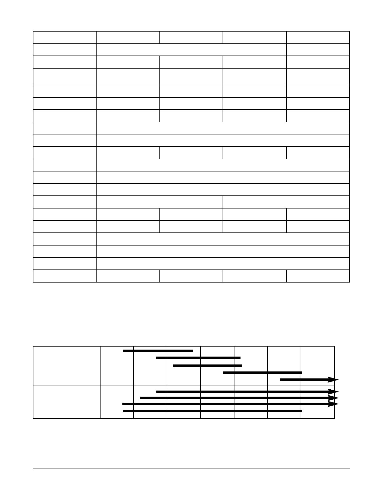
37
ESPECIFICACIONES Y CAPACIDADES DEL MOTOR
SELECTION DE ACEITE
Selección de aceite apropiado al igual que nivel de aceite es critico para conseguir vida máxima del motor. Use aceite con
alto detergente y alta calidad certificado para la clase CC y CD que debe ser designado en el contenedor. SAE 20W-40 es
recomendado para uso general y todas las temperaturas. Use la tabla de abajo para seleccionar el aceite apropiado para la
temperatura de su área.
Viscosidad -30C/-22F -20C/-4F -10C/14F 0C/32F 10C/50F 20C/68F 30C/86F 40C/104F
Español
Solo 10W
20W
20
30
40
Múltiplo 20W-40, 20W-50
15W-40, 15W-50
10W-40
10W-30
Modelo GX270 (DXGN4500) GX340 (DXGN6000) GX390 (DXGN7200) GX630 (DXGN14000)
Tipeo 4-stroke, overhead vale single cylinder, inclined 25°
4-stroke, overhead valve, V-
Twin
Desplazo 270cc (16.5 cu in) 389cc (23.7 cu in) 389cc (23.7 cu in) 688cc (42.0 cu in)
Calibre y Tiempo
73 x 58 mm
(2.9 x 2.3 in)
88 x 64 mm
(3.5 x 2.5 in)
88 x 64 mm
(3.5 x 2.5 in)
78 x 72 mm
(3.1 x 2.8 in)
Caballos neto 8.5 hp @3600rpm 10.7 hp @3600rpm 11.7 hp @3600rpm 20.2hp @3600rpm
Momento de torsión neto
14.1ft-lb @2500rpm 19.5ft-lb @2500rpm 19.5ft-lb @2500rpm 35.1ft-lb @2500rpm
Proporción de
Compresión
8.5 : 1 8.2 : 1 8.2 : 1 9.3 : 1
Sistema de Enfriamiento
Forced-air
Sistema de Ignición
Transistorized magneto
Tiempo de Ignición 25° B.T.D.C. (fixed)
Bujía BPR6ES (NGK), W20EPR-U (Nippondenso)
Carburador Horizontal type, butterfly valve
Limpiador de Aire
Dual element type
Sistema de Lubricación
Splash Forced Oil
Capacidad de Aceite
1.1l (1.16 US qt) 1.1l (1.16 US qt) 1.1l (1.16 US qt) 2.0 l (2.1 US qt)
Sistema de Arranque
Recoil Recoil Recoil/Electric Electric
Sistema de Parar Ignition primary circuit ground
Tipo de Combustible
Unleaded gasoline (86 pump octane)
PTO Rotación del Mango
Counterclockwise (from PTO side)
Peso 25.0 kg (55.1 lb) 31.5 kg (69 lb) 31.5 kg (69 lb) 44.0 kg (96.8 lb)
0068660
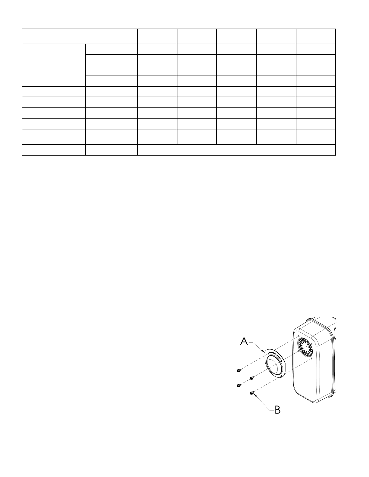
38
0068660
PROGRAMA DE MANTENIMIENTO DE MOTOR
Notas:
(1) Revise mas frecuente en áreas polvosas.
(2) Deben ser revisados a menos que un comerciante o dueño tenga la herramienta apropiada y es experto mecánicamente.
Vea el Manual de Taller de motor para instrucciones.
INSPECCION DIARIA
1. Cuerda para arranque manual
2. Nivel de Aceite de Motor
3. Cheque el Aceite de Motor y Fugas de Combustible
4. Inspeccione los cables de bujías
5. Inspeccione el Sistema de Enfriamiento para Limpieza
6. Este al tanto de Ruidos Anormales
7. Este al tanto de Vibraciones Anormales
PARACHISPAS
El servicio del parachispas debe realizarse cada 100 horas para que pueda seguir funcionando como ha sido
diseñado.
Si el motor había estado en marcha, el silenciador estará caliente. Deje que se enfrie antes de realizar el servicio
del parachispas.
DXGN4500, DXGN6000, y DXGN7200
Limpie e inspeccione el parachispas de la siguiente manera:
1. Quite el cuatro tornillos (B) y protector del parachispas (A)
del silenciador.
2. Emplee un cepillo para sacar la carbonilla acumulada en la
rejilla del parachispas. Tenga cuidado para no dañar la
rejilla.
3. El parachispas deberá estar exento de roturas y agujeros.
Reemplace el parachispas si está dañado.
4. Coloque el protector del parachispas (A) en el silenciador al
alinear los agujeros del protector con los agujeros
perforados en el silenciador. Enrosque los cuatro tornillos
(B) en los agujeros y apriételos firmemente.
DXGN14000
Vea instrucciones suministradas con Juego de Parachispas.
Español
ARTICULO
Cada Uso 1er Mes O
20 Hrs
3 Meses O
50Hrs
6 Meses
O 100Hrs
Cada Año O
300Hrs
Aceite
Cheque X
Cambie X X
Limpiador de Aire
Cheque X
Limpie X (1)
Copa de Sedimento Limpie X
Bujía Cheque-Cambie X
Atrapa chispas Limpie X
Válvula de Despeje Cheque-Ajuste X (2)
Tanque de
Combustible y Colador
Limpie X (2)
Línea de Combustible Cheque Remplace a como sea necesario
0068660
39
GUIA PARA ENCONTRAR FALLAS
Español
SINTOMAS CAUSA POSIBLE CORRECCION
MOTOR NO ARRANCA
1. Bajo Nivel de Aceite.
2. No Combustible o válvulas(s) apagadas.
3. Interruptor de arranque apagado
4. Sistema de Combustible Cerrado / Con
Fugas
5. Filtro de aire atascado.
6. Generador bajo carga al arranque.
1. Rellene con Aceite.
2. Rellene con Combustible / Prenda
válvulas.
3. Prenda el Interruptor
4. Repare el sistema de combustible.
5. Limpie o remplace el filtro de aire.
6. Desconecte la carga.
NO HAY POTENCIA
1. Interruptor atascado.
2. receptáculo GFCI atascado.
3. Interruptor con fallas.
4. Receptáculo con fallas.
5. Condensador con fallasen el alternador.
6. Diodo con fallas en el alternador.
7. Falla en el cableado del alternador.
1. Reajuste interruptor.
2. Reajuste receptáculo GFCI.
3. Remplace el interruptor.
4. Remplace el receptáculo.
5. Reemplace condensador.
6. Remplace diodos.
7. Repare o remplace el alternador.
RUIDO DE LA MAQUINA 1. Soporte Dañado.
2. Sistema exhausto Dañado.
3. Piezas flojas o sueltas.
1. Remplace soporte.
2. Repare o remplace.
3. Repare piezas flojas o sueltas.
SOBRECALENTANDOSE 1. Aperturas de ventilación bloqueadas.
2. Sobrecarga.
3. Temperatura del ambiente muy alta.
1. Despeje la aperturas de ventilación.
2. Verifique los niveles de carga.
3. Proporcione mejor ventilación para el
enfriamiento.
INTERRUPTORES ATASCADOS 1. Circuito sobrecargado.
2. Equipo o cable con fallas.
3. Interruptores con fallas.
1. Reduzca la carga.
2. Cheque, repare o remplaza.
3. Remplace interruptor.

PRAMAC America 1300 Gresham Road Marietta, GA 30062
Copyright © 2012
The following are trademarks for one or more DEWALT power tools: the yellow and black color scheme.
D
EWALT
®
, GUARANTEED TOUGH
®
and the yellow and black color scheme are trademarks of the
D
EWALT Industrial Tool Co., used under license.
PRAMAC America 1300 Gresham Road Marietta, GA 30062, a licensee of D
EWALT Industrial Tools.