
Projector
PE401H
User’s Manual
Model No.
NP-PE401H

Ver.1/01/2013
• DLP, BrilliantColor, and DLP Link are trademarks of Texas Instruments.
• IBM is a trademark or registered trademark of International Business Machines Corporation.
• Macintosh, Mac OS X, iMac, and PowerBook are trademarks of Apple Inc., registered in the U.S. and
other countries.
• Microsoft, Windows, Windows Vista, Internet Explorer, .NET Framework, and PowerPoint are
either a registered trademark or trademark of Microsoft Corporation in the United States and/or
other countries.
• MicroSaver is a registered trademark of Kensington Computer Products Group, a division of ACCO
Brands.
• Virtual Remote Tool uses WinI2C/DDC library, © Nicomsoft Ltd.
• HDMI, the HDMI Logo and High-Denition Multimedia Interface are trademarks or registered
trademarks of HDMI Licensing LLC.
• Blu-ray is a trademark of Blu-ray Disc Association
• Trademark PJLink is a trademark applied for trademark rights in Japan, the United States of
America and other countries and areas.
• CRESTRON and ROOMVIEW are registered trademarks of Crestron Electronics, Inc. in the United
States and other countries.
• Other product and company names mentioned in this user’s manual may be the trademarks or
registered trademarks of their respective holders.
NOTES
(1) The contents of this user’s manual may not be reprinted in part or whole without permission.
(2) The contents of this user’s manual are subject to change without notice.
(3) Great care has been taken in the preparation of this user’s manual; however, should you notice any
questionable points, errors or omissions, please contact us.
(4) Notwithstanding article (3), NEC will not be responsible for any claims on loss of prot or other
matters deemed to result from using the Projector.
i
English
...
Important Information
Safety Cautions
Precautions
Please read this manual carefully before using your NEC projector and keep the manual handy for future
reference.
CAUTION
To turn off main power, be sure to remove the plug from power outlet.
The power outlet socket should be installed as near to the equipment as possible, and should be
easily accessible.
CAUTION
TO PREVENT SHOCK, DO NOT OPEN THE CABINET.
THERE ARE HIGH-VOLTAGE COMPONENTS INSIDE.
REFER SERVICING TO QUALIFIED SERVICE PERSONNEL.
This symbol warns the user that uninsulated voltage within the unit may be sufcient to cause
electrical shock. Therefore, it is dangerous to make any kind of contact with any part inside of
the unit.
This symbol alerts the user that important information concerning the operation and mainte-
nance of this unit has been provided.
The information should be read carefully to avoid problems.
WARNING: TO PREVENT FIRE OR SHOCK, DO NOT EXPOSE THIS UNIT TO RAIN OR MOISTURE.
DO NOT USE THIS UNIT’S PLUG WITH AN EXTENSION CORD OR IN AN OUTLET UNLESS ALL
THE PRONGS CAN BE FULLY INSERTED.
DOC Compliance Notice (for Canada only)
This Class B digital apparatus complies with Canadian ICES-003.
Machine Noise Information Regulation - 3. GPSGV,
The highest sound pressure level is less than 70 dB (A) in accordance with EN ISO 7779.
Disposing of your used product
EU-wide legislation as implemented in each Member State requires that used electrical and elec-
tronic products carrying the mark (left) must be disposed of separately from normal household
waste. This includes projectors and their electrical accessories or lamps. When you dispose of
such products, please follow the guidance of your local authority and/or ask the shop where you
purchased the product.
After collecting the used products, they are reused and recycled in a proper way. This effort will
help us reduce the wastes as well as the negative impact such as mercury contained in a lamp
to the human health and the environment at the minimum level. The mark on the electrical and
electronic products only applies to the current European Union Member States.
WARNING TO CALIFORNIA RESIDENTS:
Handling the cables supplied with this product will expose you to lead, a chemical known to the State of
California to cause birth defects or other reproductive harm. WASH HANDS AFTER HANDLING.
ii
English
...
Important Information
RF Interference (for USA only)
WARNING
The Federal Communications Commission does not allow any modications or changes to the unit
EXCEPT those specied by NEC Display Solutions of America, Inc. in this manual. Failure to comply with
this government regulation could void your right to operate this equipment. This equipment has been test-
ed and found to comply with the limits for a Class B digital device, pursuant to Part 15 of the FCC Rules.
These limits are designed to provide reasonable protection against harmful interference in a residential
installation. This equipment generates, uses, and can radiate radio frequency energy and, if not installed
and used in accordance with the instructions, may cause harmful interference to radio communications.
However, there is no guarantee that interference will not occur in a particular installation.
If this equipment does cause harmful interference to radio or television reception, which can be deter-
mined by turning the equipment off and on, the user is encouraged to try to correct the interference by one
or more of the following measures:
• Reorient or relocate the receiving antenna.
• Increase the separation between the equipment and receiver.
• Connect the equipment into an outlet on a circuit different from that to which the receiver is connected.
• Consult the dealer or an experienced radio / TV technician for help.
For UK only: In UK, a BS approved power cord with moulded plug has a Black (ve Amps) fuse installed for
use with this equipment. If a power cord is not supplied with this equipment please contact your supplier.
Important Safeguards
These safety instructions are to ensure the long life of your projector and to prevent re and shock. Please
read them carefully and heed all warnings.
Installation
• Do not place the projector in the following conditions:
- on an unstable cart, stand, or table.
- near water, baths, or damp rooms.
- in direct sunlight, near heaters, or heat radiating appliances.
- in a dusty, smoky or steamy environment.
- on a sheet of paper, cloth, rugs, carpets, or any objects which are damaged or affected by heat.
• If you wish to have the projector installed on the ceiling:
- Do not attempt to install the projector yourself.
- The projector must be installed by qualied technicians in order to ensure proper operation and reduce
the risk of bodily injury.
- In addition, the ceiling must be strong enough to support the projector and the installation must be in
accordance with any local building codes.
- Please consult your dealer for more information.
WARNING
• Do not use any other object than the projector’s sliding lens cover to
cover the lens while the projector is on. Doing so can cause the object to
get extremely hot, and possibly resulting in a re or damage due to the
heat emitted from the light output.
• Do not place any objects, which are easily affected by heat, in front of
the projector lens. Doing so could lead to the object melting from the
heat that is emitted from the light output.
iii
English
...
Important Information
Fire and Shock Precautions
• Ensure that there is sufcient ventilation and that vents are unobstructed to prevent the build-up of heat
inside your projector. Allow at least 4 inches (10cm) of space between your projector and a wall.
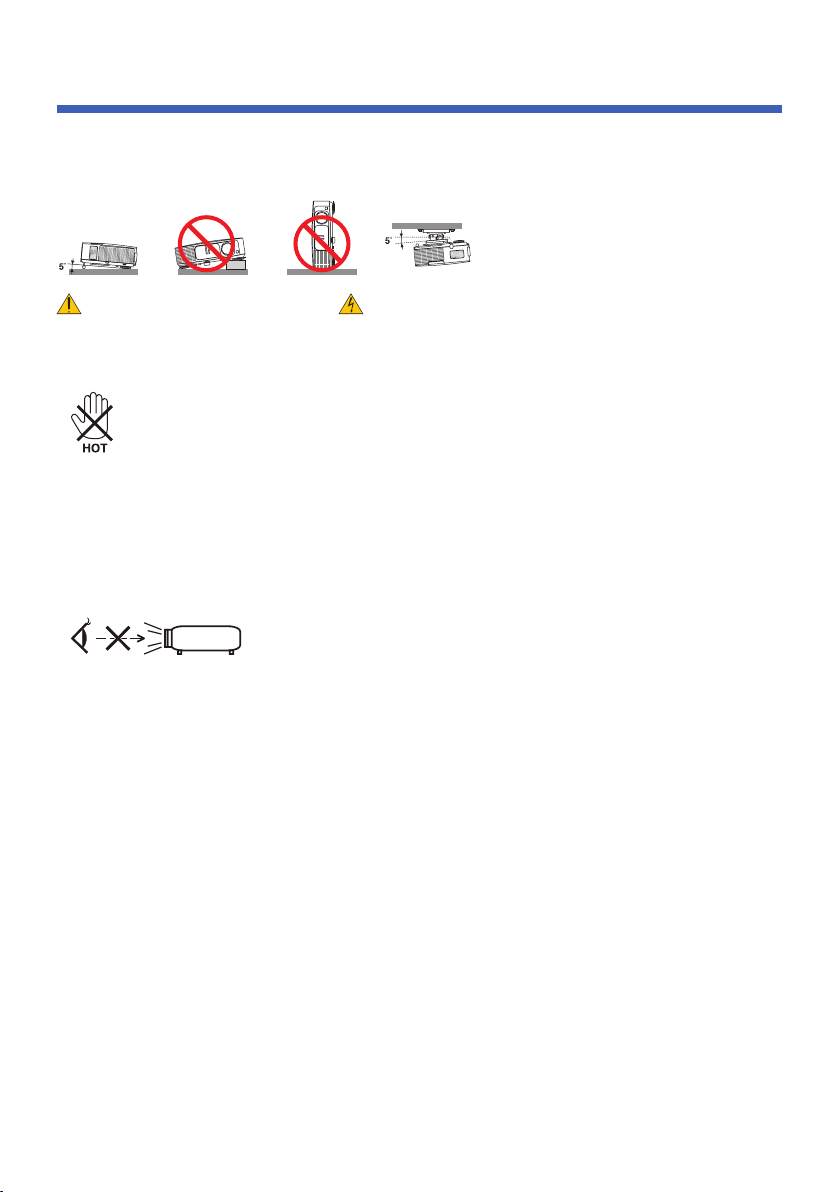
• Do not try to touch the ventilation outlet as it can become heated while the projector is turned on and im-
mediately after the projector is turned off.
• Prevent foreign objects such as paper clips and bits of paper from falling into your projector. Do not at-
tempt to retrieve any objects that might fall into your projector. Do not insert any metal objects such as a
wire or screwdriver into your projector. If something should fall into your projector, disconnect it immedi-
ately and have the object removed by a qualied service personnel.
• Do not place any objects on top of the projector.
• Do not touch the power plug during a thunderstorm. Doing so can cause electrical shock or re.
• The projector is designed to operate on a power supply of 100-240V AC 50/60 Hz. Ensure that your power
supply ts this requirement before attempting to use your projector.
• Do not look into the lens while the projector is on. Serious damage to your eyes could result.
• Keep any items (magnifying glass etc.) out of the light path of the projector. The light path being projected
from the lamp is extensive, therefore any kind of abnormal objects that can redirect light coming out of the
lamp, can cause unpredictable outcome such as a re or injury to the eyes.
• Do not block the light path between the light source and the lamp with any objects. Doing so could cause
the object to catch on re.
• Do not place any objects, which are easily affected by heat, in front of the projector lamp or a projector
exhaust vent.
Doing so could lead to the object melting or getting your hands burned from the heat that is emitted from
the light output and exhaust.
• Handle the power cord carefully. A damaged or frayed power cord can cause electric shock or re.
- Do not use any power cord other than the one supplied.
- Do not bend or tug the power cord excessively.
- Do not place the power cord under the projector, or any heavy object.
- Do not cover the power cord with other soft materials such as rugs.
- Do not heat the power cord.
- Do not handle the power plug with wet hands.
• Turn off the projector, unplug the power cord and have the projector serviced by a qualied service per-
sonnel under the following conditions:
- When the power cord or plug is damaged or frayed.
- If liquid has been spilled into the projector, or if it has been exposed to rain or water.
- If the projector does not operate normally when you follow the instructions described in this user’s
manual.
Place the projector in a horizontal position
The tilt angle of the projector should not exceed 5 degrees, nor should the projector be installed in any way
other than the desktop and ceiling mount, otherwise lamp life could decrease dramatically.
iv
English
...
Important Information
Remote Control Precautions
• Handle the remote control carefully.
• If the remote control gets wet, wipe it dry immediately.
• Avoid excessive heat and humidity.
• Do not short, heat, or take apart batteries.
• Do not throw batteries into re.
• If you will not be using the remote control for a long time, remove the batteries.
• Ensure that you have the batteries’ polarity (+/–) aligned correctly.
• Do not use new and old batteries together, or use different types of batteries together.
• Dispose of used batteries according to your local regulations.
Lamp Replacement
• Use the specied lamp for safety and performance.
• To replace the lamp, follow all instructions provided on pages 63-64.
• Be sure to replace the lamp when the message [THE LAMP HAS REACHED THE END OF ITS USABLE
LIFE. PLEASE REPLACE THE LAMP.] appears. If you continue to use the lamp after the lamp has
reached the end of its usable life, the lamp bulb may shatter, and pieces of glass may be scattered in the
lamp case. Do not touch them as the pieces of glass may cause injury.
If this happens, contact your dealer for lamp replacement.
A Lamp Characteristic
The projector has a high-pressure mercury lamp as a light source.
A lamp has a characteristic that its brightness gradually decreases with age. Also repeatedly turning the
lamp on and off will increase the possibility of its lower brightness.
CAUTION:
• DO NOT TOUCH THE LAMP immediately after it has been used. It will be extremely hot. Turn the
projector off and then disconnect the power cord. Allow at least one hour for the lamp to cool before
handling.
• When removing the lamp from a ceiling-mounted projector, make sure that no one is under the projec
-
tor. Glass fragments could fall if the lamp has been burned out.
Note for US Residents
The lamp in this product contains mercury. Please dispose according to Local, State or Federal Laws.
- If the projector has been dropped or the cabinet has been damaged.
- If the projector exhibits a distinct change in performance, indicating a need for service.
• Disconnect the power cord and any other cables before carrying the projector.
• Turn off the projector and unplug the power cord before cleaning the cabinet or replacing the lamp.
• Turn off the projector and unplug the power cord if the projector is not to be used for an extended period
of time.
• When using a LAN cable:
For safety, do not connect to the connector for peripheral device wiring that might have excessive voltage.

v
English
...
Important Information
About High Altitude mode
• Set [FAN MODE] to [HIGH SPEED] when using the projector at altitudes approximately 2500 feet/760
meters or higher.
• Using the projector at altitudes approximately 2500 feet/760 meters or higher without setting to [HIGH
SPEED] can cause the projector to overheat and the protector could shut down. If this happens, wait a
couple minutes and turn on the projector.
• Using the projector at altitudes less than approximately 2500 feet/760 meters and setting to [HIGH
SPEED] can cause the lamp to overcool, causing the image to icker. Switch [FAN MODE] to [AUTO].
• Using the projector at altitudes approximately 2500 feet/760 meters or higher can shorten the life of opti-
cal components such as the lamp.
About Copyright of original projected pictures:
Please note that using this projector for the purpose of commercial gain or the attraction of public attention
in a venue such as a coffee shop or hotel and employing compression or expansion of the screen image with
the following functions may raise concern about the infringement of copyrights which are protected by copy-
right law. [ASPECT RATIO], [KEYSTONE], Magnifying feature and other similar features.
[NOTE] Power management function
The projector has power management functions.
To reduce power consumption, the power management functions (1 and 2) are factory-preset in the
following way. To control the projector via a LAN or serial cable connection, use the on-screen menu to
change the settings for 1 and 2.
1. STANDBY MODE (Factory preset: POWER-SAVING)
To control the projector from an external device, select [NORMAL] for [STANDBY MODE].
When [POWER-SAVING] is selected for [STANDBY MODE], the following connectors and functions will
not work:
- PC CONTROL connector, MONITOR OUT connector, AUDIO OUT connector, LAN functions, Mail
Alert function, DDC/CI (Virtual Remote Tool)
2. AUTO POWER OFF (Factory default: 30 minutes)
To control the projector from an external device, select [0] for [AUTO POWER OFF (MIN)].
-When [30] is selected for [AUTO POWER OFF], you can enable the projector to automatically turn off in
30 minutes if there is no signal received by any input or if no operation is performed.
Health precautions to users viewing 3D images
• Before viewing, be sure to read health care precautions that may be found in the user’s manual included
with your LCD shutter eyeglasses or your 3D compatible content such as DVDs, video games, comput-
er’s video les and the like.
To avoid any adverse symptoms, heed the following:
- Do not use LCD shutter eyeglasses for viewing any material other than 3D images.
- Allow a distance of 2 m/7 feet or greater between the screen and a user. Viewing 3D images from too
close a distance can strain your eyes.
- Avoid viewing 3D images for a prolonged period of time. Take a break of 15 minutes or longer after
every hour of viewing.
- If you or any member of your family has a history of light-sensitive seizures, consult a doctor before
viewing 3D images.
- While viewing 3D images, if you get sick such as nausea, dizziness, queasiness, headache, eyestrain,
blurry vision, convulsions, and numbness, stop viewing them. If symptoms still persist, consult a doc-
tor.

1
... English
Table of Contents
Table of Contents...............................1
Usage Notice .....................................2
Precautions .........................................2
Introduction ........................................4
Product Features ................................4
Package Overview ..............................6
Product Overview ...............................7
Projector .................................................7
Connection Ports .................................... 8
Control Panel.......................................... 9
Attaching the Cable Cover ...................10
Remote Control .................................... 11
Battery Installation ................................ 14
Using the Downloadable Software ....... 15
Viewing 3D Images .............................. 24
Installation .......................................25
Connecting the Projector ..................25
Connect to Computer/Notebook ........... 25
Connect to Video Sources .................... 26
Powering On/Off the Projector ..........27
Powering On the Projector ................... 27
Powering Off the Projector ................... 28
Warning Indicator ................................. 29
Adjusting the Projected Image ..........30
Adjusting the Height of Projector Image 30
Adjusting the Projector Zoom/Focus .... 31
Adjusting Projection Image Size........... 31
User Controls...................................33
On Screen Display ............................33
How to operate ....................................33
Menu Tree ........................................... 34
IMAGE | GENERAL .............................. 36
IMAGE | ADVANCED ........................... 38
SCREEN | GENERAL .......................... 40
SCREEN | 3D SETTING ...................... 41
SETTING | GENERAL .......................... 42
SETTING | SIGNAL .............................. 44
SETTING | ADVANCED ....................... 45
SETTING | ADVANCED | SECURITY .. 46
SETTING | ADVANCED | NETWORK .. 48
OPTIONS | GENERAL ......................... 51
OPTIONS | LAMP/FILTER SETTINGS 52
OPTIONS | INFORMATION ................. 53
OPTIONS | ADVANCED ....................... 54
Appendices ......................................55
Troubleshooting ................................55
Cleaning the Filter .............................60
Replacing the lamp ..........................63
Cleaning procedure for the lens ........65
Specications ....................................66
Compatibility Modes .........................68
VGA Analog .......................................... 68
HDMI Digital ......................................... 70
Ceiling Mount Installation ..................73
Cabinet Dimensions ..........................74
Pin Assignments of D-Sub
COMPUTER Input Connector ...........75
PC Control Codes and Cable
Connection ........................................76
Troubleshooting Check List ..............77
REGISTER YOUR PROJECTOR! ...79

2
English ...
Usage Notice
Precautions
Follow all warnings, precautions and maintenance as recom-
mended in this user’s guide to maximize the life of your unit.
■ Warning-
This projector will detect the life of the lamp
itself. Please be sure to change the lamp when it
shows warning messages.
■ Warning-
Reset the “
CLEAR LAMP HOURS” function
from the on-screen display “OPTIONS |LAMP/
FILTER SETTINGS” menu after replacing the
lamp module (refer to page 52).
■ Warning-
When switching the projector off, please ensure
the cooling cycle has been completed before
disconnecting power.
■ Warning-
Turn on the projector rst and then the signal
sources.
■ Warning-
When the lamp reaches the end of its life, it will
burn out and may make a loud popping sound.
If this happens, the projector will not turn back
on until the lamp module has been replaced. To
replace the lamp, follow the procedures listed
under “Replacing the Lamp”.
Turkish RoHS information relevant for Turkish market
EEE Yönetmeliğine Uygundur.
This device is not intended for use in the direct eld of view
at visual display workplaces. To avoid incommoding reec-
tions at visual display workplaces this device must not be
placed in the direct eld of view.
High gain type screens are not optimal for use with this
projector. The lower the screen gain (i.e., screen gain on the
order of 1), the better the appearance of the projected image.

3
... English
Usage Notice
Do:
■ Turn off the product before cleaning.
■ Use a soft cloth moistened with mild detergent to clean the
display housing.
■ Disconnect the power plug from AC outlet if the product is not
being used for a long period of time.
■ If the lens is soiled, use a commercially available cleaning cloth
for lens.
Do not:
■ Use abrasive cleaners, waxes or solvents to clean the unit.
■ Use under the following conditions:
- Extremely heat, cold or humidity.
- In areas susceptible to excessive dust and dirt.
- In direct sunlight.
- Move the projector by holding the cable cover.
- Hang from the projector in a ceiling or wall mounted instal-
lation.
- Apply excessively strong pressure against the lens.
- Keep nger prints off the lens surface.

4
English ...
Introduction
Product Features
■ High resolution
Full HD (1920 x 1080) support.
■ x 1.7 Zoom ratio
Wide zoom ratio provide the easy to set up for the
different situation.
■ Quick Power Off, Direct Power Off
The projector can be put away immediately after the projec-
tor is powered down. No cool down period is required after
the projector is turned off from the remote control or cabinet
control panel.
The projector has a feature called “Direct Power Off”. This fea-
ture allows the projector to be turned off (even when project-
ing an image) by using the Main Power Switch or disconnect-
ing the AC power supply. To turn off the AC power supply
when the projector is powered on, use a power strip equipped
with a switch and a breaker.
■ 0.5 W in standby condition with energy saving technology
Selecting [POWER-SAVING] for [STANDBY MODE] from
the menu can put the projector in power-saving mode that
consumes only 0.5 W (typical value).
■ Two HDMI input ports provide digital signal
The two HDMI inputs provide HDCP compatible digital sig-
nals. The HDMI input also supports audio signal.
■ 8 W + 8 W built-in speaker for an integrated audio solution
Powerful 8 watt + 8 watt stereo speakers provide volume need
for large rooms.
■ 3D features supported
The projector can support following format by DLP
®
Link.
- HDMI 1.4a 3D
- 120Hz 3D
- HQFS 3D

5
... English
Introduction
■ Integrated RJ-45 connector for wired networking capability
The customer can control the projector by own computer via
Wired LAN.
■ Software programs (User Supportware)
Two programs: Virtual Remote Tool, PC Control Utility Pro
4/Pro 5, which can be be downloaded from our website.
■ Preventing unauthorized use of the projector
Enhanced smart security settings for keyword protection,
cabinet control panel lock, security slot, and security chain
opening to help prevent unauthorized access, adjustments and
theft deterrence.
6
English ...
Introduction
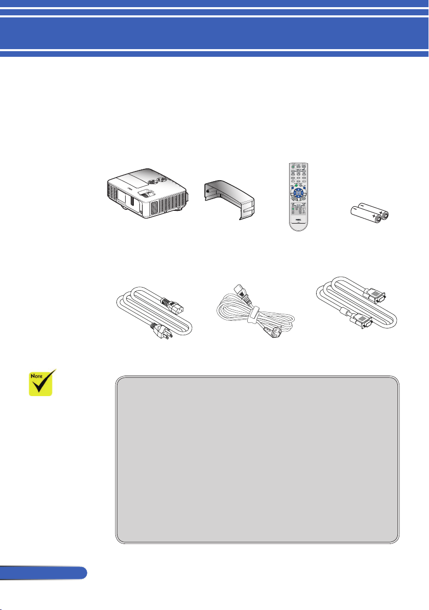
Power Cord x1
Remote Control
(P/N:79TC3051)
Projector
Package Overview
This projector comes with all the items shown below. Check
to make sure your unit is completed. Contact your dealer
immediately if anything is missing.
Due to the differ-
ence in applications
for each country, some
regions may have dif-
ferent accessories.
Documentation:
NEC Projector CD-ROM
(P/N: 7N951911)
Quick Setup Guide (P/N:
7N8N3631)
Important Information (For
North America: 7N8N3611)
(For Other countries than
North America: 7N8N3611
and 7N8N3621)
Batteries (AAAx2)
For North America:
Limited Warranty
For Europe:
Guarantee Policy
For customers in Europe:You will nd our current valid Guarantee
Policy on our Web Site:www.nec-display-solutions.com
Cable Cover
Computer Cable (VGA)
(P/N:79TC5061)
US (P/N:79TC5021) EU (P/N:79TC5031)
7
... English
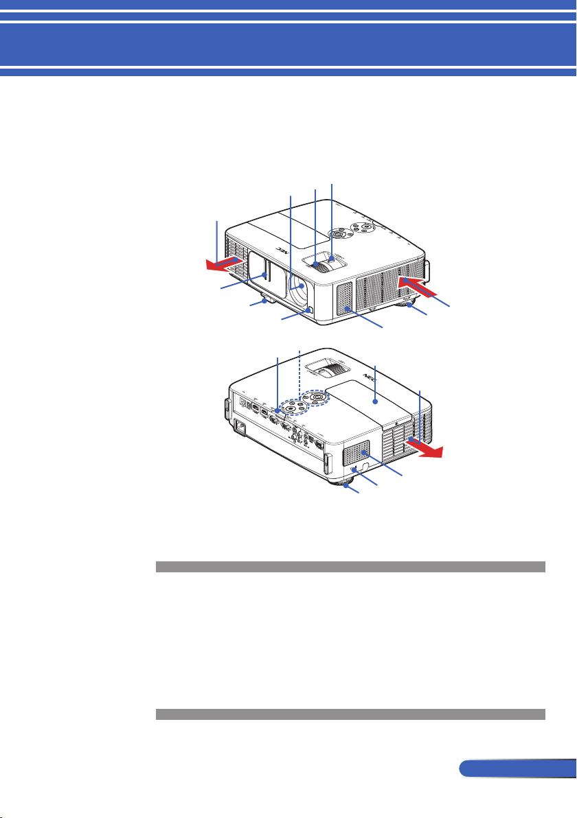
Introduction
1. Lens Cover
2. Tilt Foot
3. Remote Sensors
4. Lens
5. Focus Ring
6. Zoom Lever
7. Speakers
8. Rear Feet
Projector
Product Overview
9. Lamp Cover
10. Control Panel
11. Kensington
TM
Lock Port
(This security slot sup-
ports the MicroSaver
®
Security System)
12. Ventilation (intake)
13. Ventilation (exhaust)
13
12
4
5
7
6
8
1
2
3
9
13
10
8
11
7
3
8
English ...
Introduction
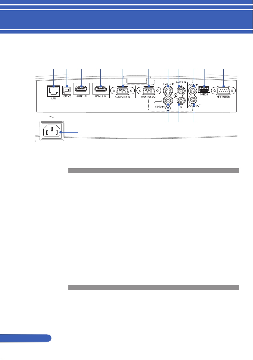
Connection Ports
1. LAN Connector (RJ-45)
2. SERVICE Port (for service purpose only)
3. HDMI 1 IN Connector
4. HDMI 2 IN Connector
5. COMPUTER IN Connector
6. MONITOR OUT Connector
7. S-VIDEO IN Connector
8. AUDIO IN L Connector
9. AUDIO IN Jack (for COMPUTER IN)
10. OPTION Connector (for future use)
11. PC CONTROL Connector
12. AC IN
13. VIDEO IN Connector
14. AUDIO IN R Connector
15. AUDIO OUT Connector
1 2 3 4 5 6 7 8 9 10 11
13 14 15
12
9
... English
Introduction
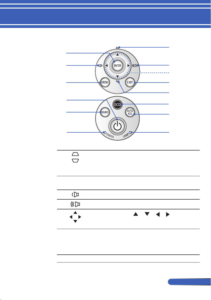
Control Panel
1 KEYSTONE
Correction
Adjust the image to compensate
for distortion caused by tilt-
ing the projector (vertical ± 40
degrees).
2
ENTER Conrm your section of items in
sub menu operation.
3
VOLUME - Decrease speaker volume.
4 VOLUME + Increase speaker volume.
5 Four
Directional
Select Keys
Use or or or to select
items or make adjustments to
your selection.
6 MENU Press “MENU” to launch the
Onscreen display (OSD), back to
the top level of OSD for the OSD
main menu operation
7 EXIT
Exit the settings.
10
12
11
13
8
5
1
1
7
4
6
3
9
2
10
English ...
Introduction
8 POWER ON/
OFF and LED
indicator
Power on the projector. Refer to
the “Power On/Off the Projec-
tor” section on pages 27-28.
9 ECO Dim the projector lamp which
will lower power consumption
and extend the lamp life. (refer
to page
52)
10 SOURCE Press “SOURCE” to select an
input signal.
11 AUTO ADJ. Automatically synchronize the
projector to the input source.
12 STATUS LED Indicate the projector’s tempera-
ture status.
13 LAMP LED Indicate the projector’s lamp
status.
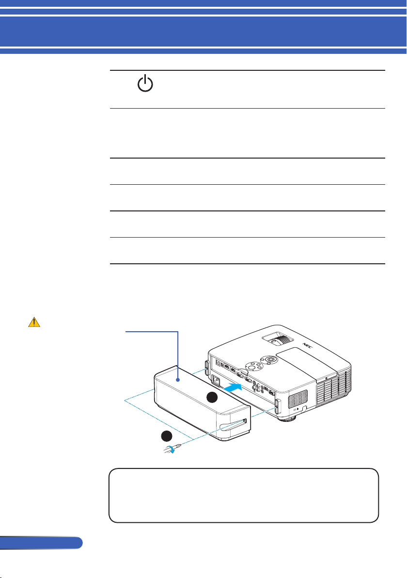
Attaching the Cable Cover
Procedure for Attaching the Cable Cover:
1. Mount the cable cover to the projector.
2. Tighten two screws on both sides of the cable cover.
Cable Cover
1
2
CAUTION:
• Be sure to tighten
the screws after
attaching the cable
cover. Failure to do
so may cause the
cable cover to come
off and fall, result-
ing in injury or
damage to the cable
cover.
• Do not put bundled
cables in the cable
cover. Failure to do
so may damage the
power cord, result-
ing a re.
11
... English
Introduction
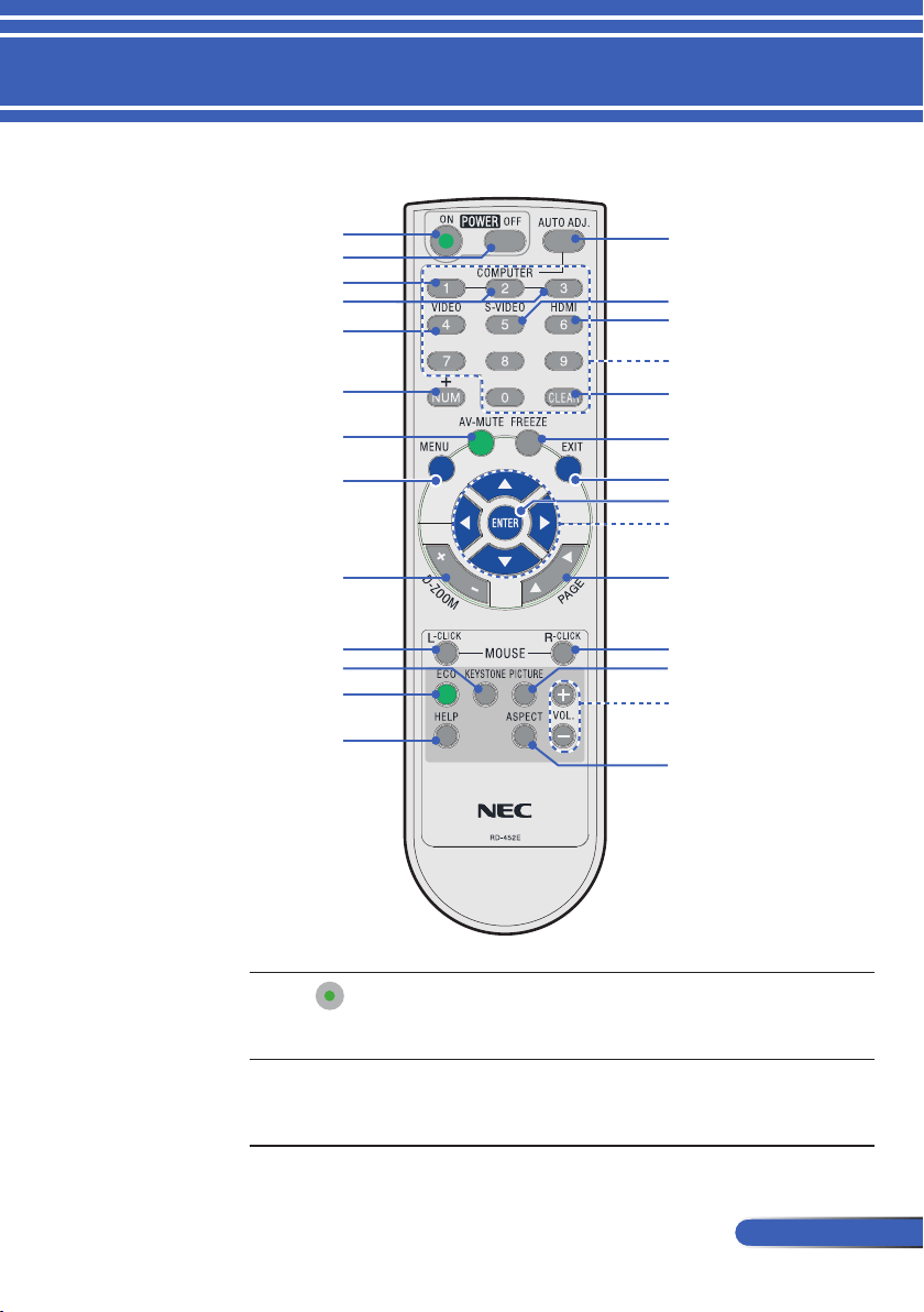
Remote Control
1 POWER ON Power on the projector. Refer to
the “Power On/Off the Projec-
tor” section on pages 27-28.
2 POWER OFF Power off the projector.Refer to
the “Power On/Off the Projec-
tor” section on pages 27-28.
3
4
5
15
8
9
10
12
16
19
21
23
24
26
22
11
1
14
2
6
18
17
7
20
13
25
27

12
English ...
Introduction
3 COMPUTER 1 Press “1” to choose COMPUTER
IN connector.
4 COMPUTER 2
COMPUTER 3
No function.
5 VIDEO Press “VIDEO” to choose VIDEO
IN connector.
6 NUM Select password. When you
input a password, you must
press “NUM” and other number
button simultaneously.
7 AV-MUTE Momentarily turn off/on the
audio and video.
8 MENU Press “MENU” to launch the
Onscreen display (OSD), back to
the top level of OSD for the OSD
main menu operation
9 D-ZOOM Zoom in/out the projected im-
age.
10 L-CLICK
Mouse left click.
11 KEYSTONE
Correction
Adjust the image to compensate
for distortion caused by tilt-
ing the projector (vertical ± 40
degrees).
12 ECO Dim the projector lamp which
will lower power consumption
and extend the lamp life. (refer
to page
52)
13 HELP This function ensures easy setup
and operation.
14 AUTO ADJ. Automatically synchronize the
projector to the input source.
15 S-VIDEO
Press “S-VIDEO” to choose
S-VIDEO IN connector.
16 HDMI Press “HDMI” to choose HDMI 1
IN or HDMI 2 IN connector.
13
... English
Introduction
17 Number Button Select password.
18 CLEAR Clear the number while you
input the password.
19 FREEZE Freeze To pause the screen im-
age. Press again to resume the
screen image.
20 EXIT
Exit the settings.
21 ENTER Conrm your section of items in
sub menu operation.
22
Four
Directional
Select Buttons
Use or or or to select
items or make adjustments to
your selection. When the image
is enlarged by using the D-
ZOOM + button, the , , or
button moves the image.
23 PAGE Use this button to page up or
page down.
24 R-CLICK Mouse right click.
25 PICTURE
Mode
Select the Picture mode from
PRESENTATION, HIGH-
BRIGHT, VIDEO, MOVIE, sRGB,
BLACKBOARD, USER1, and
USER2.
26 VOL. +/-
Increase/decrease speaker vol-
ume.
27 ASPECT Use this function to choose your
desired aspect ratio. (refer to
page 40)
When the
reduced image is
displayed, the ,
, or button is
not available to move
the image.
14
English ...
Introduction
Battery Installation
Remote Control Precautions
• Handle the remote control carefully.
• If the remote control gets wet, wipe it dry immediately.
• Avoid excessive heat and humidity.
• Do not place the battery upside down.
• Replace only with the same or equivalent type recommended by
the manufacturer.
• Dispose of used batteries according to your local regulations
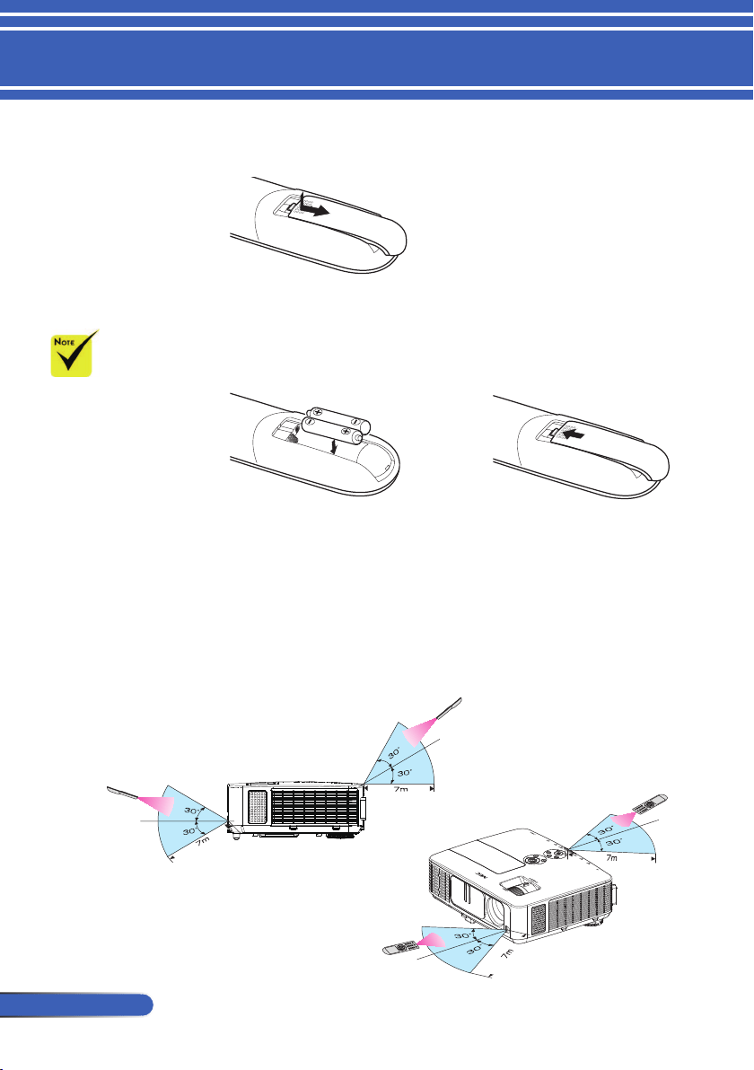
1. Press rmly and slide the battery cover off.
2. Install new batteries (AAA).
Ensure that you have the
batteries’ polarity (+/–)
aligned correctly.
3. Slip the cover back over the
batteries until it snaps into
place. Do not mix different
types of batteries or new and
old batteries.
The infrared signal
operates by line-of-
sight up to a distance
of about 22 feet/7 m
and within a 60-degree
angle of the remote
sensor on the projector
cabinet.
The projector will
not respond if there
are objects between
the remote control
and the sensor, or if
strong light falls on the
sensor. Weak batteries
will also prevent the
remote control from
properly operating the
projector.
15
... English
Introduction
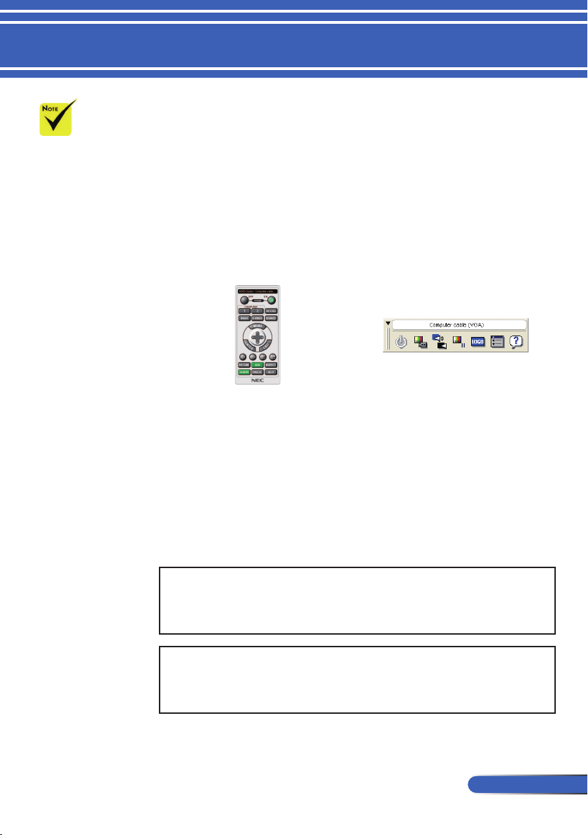
Using the Downloadable Software
Using the Computer Cable (VGA) to Operate the
Projector (Virtual Remote Tool)
Using the utility software “Virtual Remote Tool” that you can
download from our web site (http://www.nec-display.com/
dl/en/index.html), Virtual Remote screen (or toolbar) can be
displayed on your computer screen.
This will help you perform operations such as projector’s
power on or off and signal selection via the computer cable
(VGA), serial cable, or LAN connection.
Virtual Remote screen Toolbar
This section provides an outline of preparation for use of Virtual
Remote Tool.
For information on how to use Virtual Remote Tool, see Help of Vir-
tual Remote Tool. (-> page 19)
• Step 1: Install Virtual Remote Tool on the computer. (-> page
16)
• Step 2: Connect the projector to the computer. (-> page
17)
• Step 3: Start Virtual Remote Tool. (-> page
18)
TIP:
• Virtual Remote Tool can be used with a LAN and a serial connection.
• For update information on Virtual Remote Tool, visit our website:
http://www.nec-display.com/dl/en/index.html
TIP:
• The projector’s COMPUTER IN connector supports DDC/CI (Display Data
Channel Command Interface). DDC/CI is a standard interface for bidirec-
tional communication between display/projector and computer.
When “Computer
IN” is selected for
input, the Virtual
Remote screen or the
toolbar will be dis-
played as well as your
computer screen.
Use the supplied
computer cable (VGA)
to connect the COM-
PUTER IN connector
directly with the moni-
tor output connector
of the computer to use
Virtual Remote Tool.
Using a switcher or
other cables than the
supplied computer
cable (VGA) may
cause failure in signal
communication.
VGA cable connector:
Pin Nos. 12 and 15 are
required for DDC/CI.
Virtual Remote
Tool may not work
depending on your
computer’s specica-
tions and version of
graphic adapters or
drivers.
The projector does
not support the LAN
automatic search fea-
ture of Virtual Remote
Tool. To connect the
projector, register an
IP address manually.
16
English ...
Introduction
Step 1: Install Virtual Remote Tool on the computer
• Supported OS
Virtual Remote Tool will run on the following operating systems.
Windows 8 *1, Windows 8 Pro *1, Windows 8 Enterprise *1,
Windows 7 Home Basic, Windows 7 Home Premium, Windows 7 Professional,
Windows 7 Enterprise, Windows 7 Ultimate
Windows Vista Home Basic, Windows Vista Home Premium, Windows Vista Business,
Windows Vista Enterprise, Windows Vista Ultimate
Windows XP Home Edition *1, Windows XP Professional *1
*1: To run Virtual Remote Tool, “Microsoft .NET Framework Version 2.0” is
required. The Microsoft .NET Framework is available from Microsoft’s web
page. Install the Microsoft .NET Framework Version 2.0, 3.0 or 3.5 on your
computer.
1 Download the updated VRT exe le from our web site
(http://www.nec-display.com/dl/en/index.html).
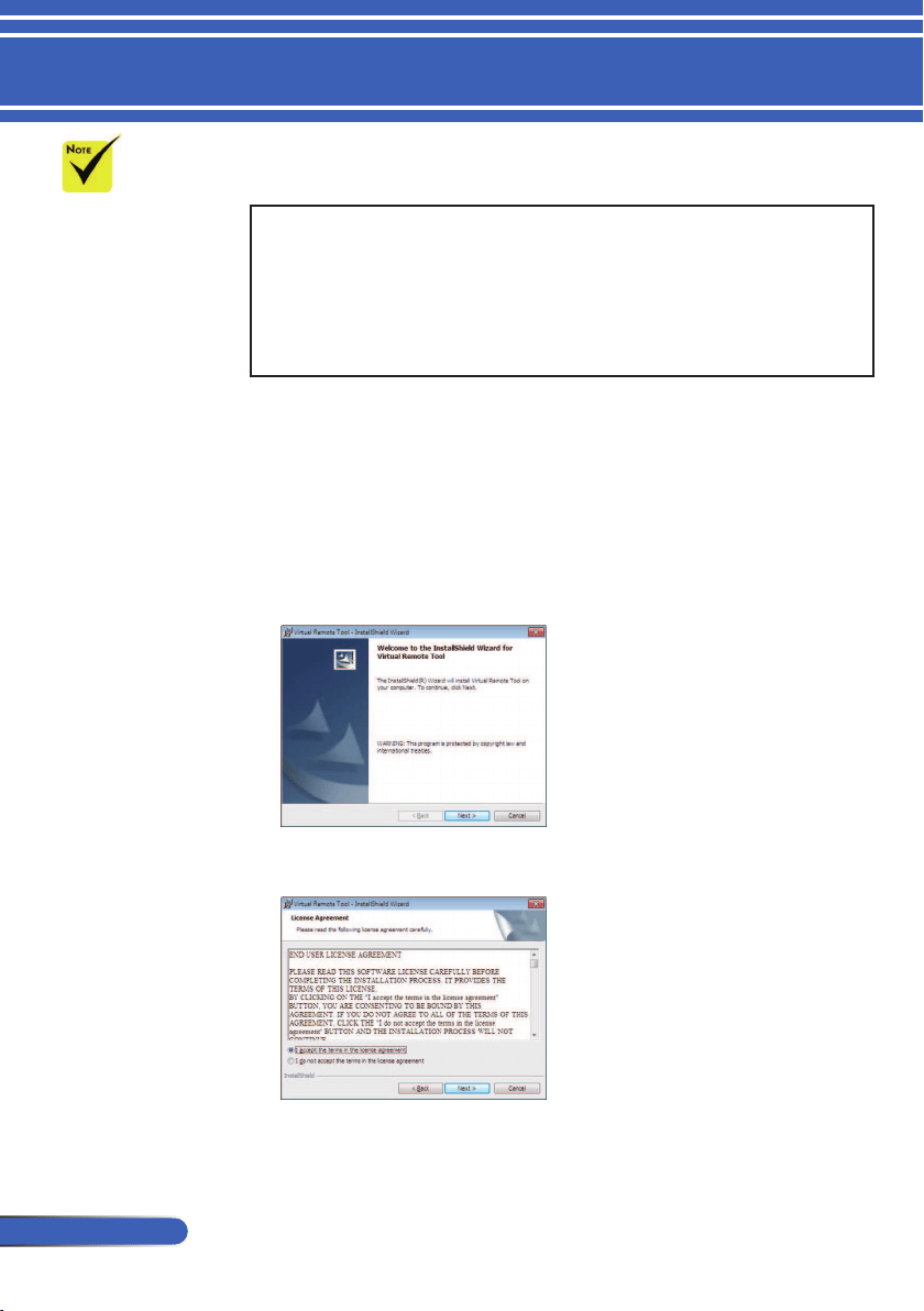
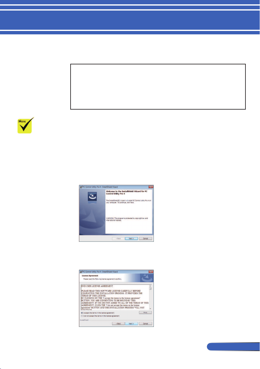
2 Double-click the VRT. exe icon.
The Installer will start and the Wizard screen will appear.
3 Click “Next”.
“END USER LICENSE AGREEMENT” screen will be displayed.
Read “END USER LICENSE AGREEMENT” carefully.
4 If you agree, click “I accept the terms in the license agreement”
and then
click “Next”.
To install or unin-
stall the program, the
Windows user account
must have [Admin-
istrator] privilege
(Windows 8, Windows
7, Windows Vista and
Windows XP)
Exit all running
programs before
installation. If another
program is running,
the installation may
not be completed.
17
... English
Introduction
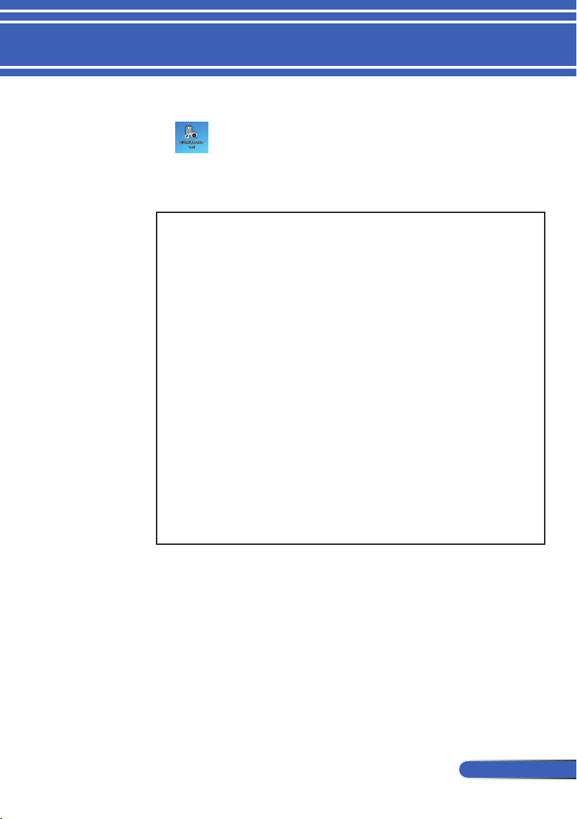
Follow the instructions on the installer screens to complete the
installation.
After the installation is completed, the shortcut icon for Virtual
Remote Tool
TIP:Uninstalling Virtual Remote Tool
• Preparation:
Exit Virtual Remote Tool before uninstalling. To uninstall Virtual Remote
Tool, the Windows user account must have “Administrator” privilege
(Windows 8, Windows 7 and Windows Vista) or “Computer Administra-
tor” privilege (Windows XP).
• For Windows 7/Windows Vista
1 Click “Start” and then “Control Panel”.
The Control Panel window will be displayed.
2 Click “Uninstall a program” under “Programs”
The “Programs and Features” window will be displayed.
3 Select Virtual Remote Tool and click it.
4 Click “Uninstall/Change” or “Uninstall”.
When the “User Account Control” window is displayed, click “Continue”.
Follow the instructions on the screens to complete the uninstallation.
• For Windows XP
1 Click “Start” and then “Control Panel”.
The Control Panel window will be displayed.
2 Double-click “Add / Remove Programs”.
The Add / Remove Programs window will be displayed.
3 Click Virtual Remote Tool from the list and then click “Remove”.
Follow the instructions on the screens to complete the uninstallation.
Step 2: Connect the projector to the computer
1 Use the supplied computer cable (VGA) to connect the COMPUTER IN
connector of the projector directly with the monitor output connector of the
computer.
2 Connect the supplied power cord to the AC IN of the projector and the wall
outlet.
The projector is in the standby condition.
18
English ...
Introduction
TIP:
• When Virtual Remote Tool starts for the rst time, “Easy Setup”
window will be displayed to navigate your connections.
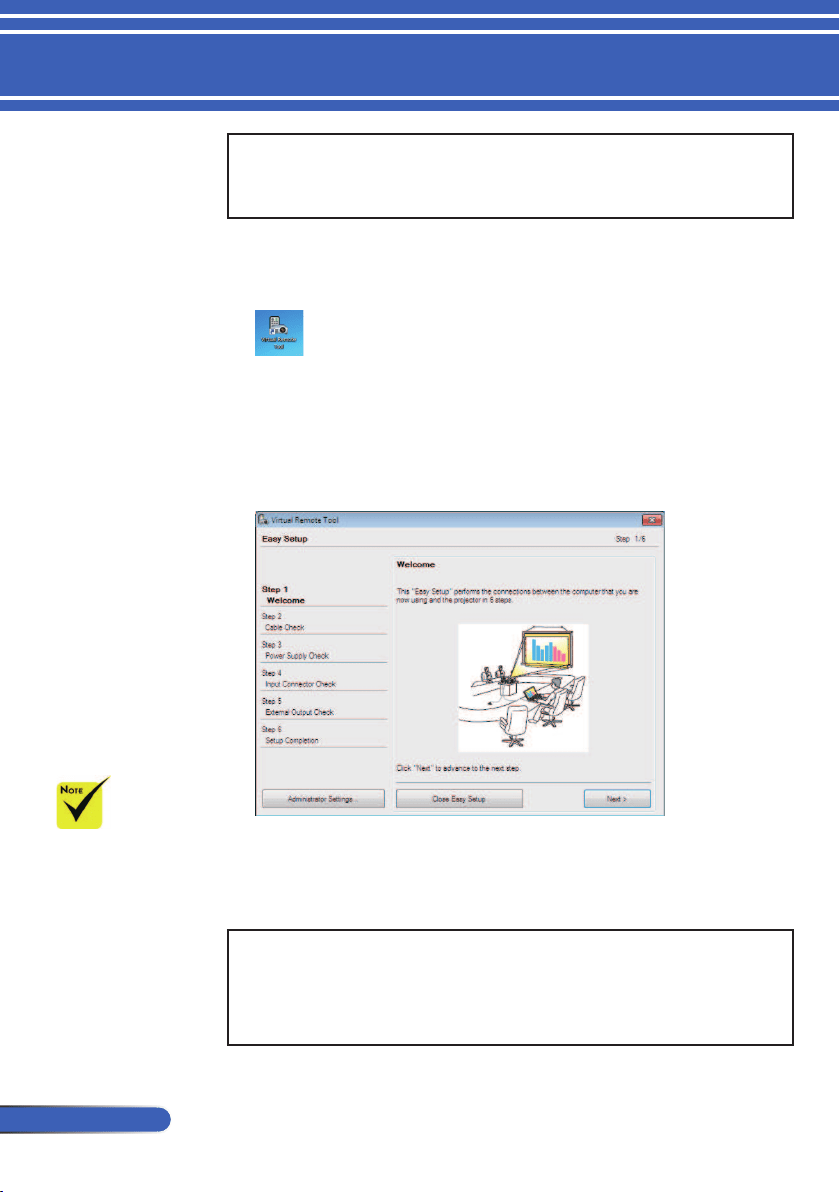
Step 3: Start Virtual Remote Tool
Start using the shortcut icon
Start from the Start menu
Click [Start] -> [All Programs] or [Programs] -> [NEC Projector
User Supportware] -> [Virtual Remote Tool] -> [Virtual Remote
Tool].
When Virtual Remote Tool starts for the rst time, “Easy Setup”
window will be displayed.
Follow the instructions on the screens.
When “Easy Setup” is completed, the Virtual Remote Tool screen
will be displayed.
TIP:
• The Virtual Remote Tool screen (or Toolbar) can be displayed without
displaying “Easy Setup” window.
To do so, click to place a check mark for “Do not use Easy Setup next time”
on the screen at Step 6 in “Easy Setup”.
When “Power-
Saving” is selected for
“Standby Mode” from
the menu, the projector
cannot be controlled
via the computer cable
(VGA), serial cable or
network (wired LAN)
connection.
19
... English
Introduction
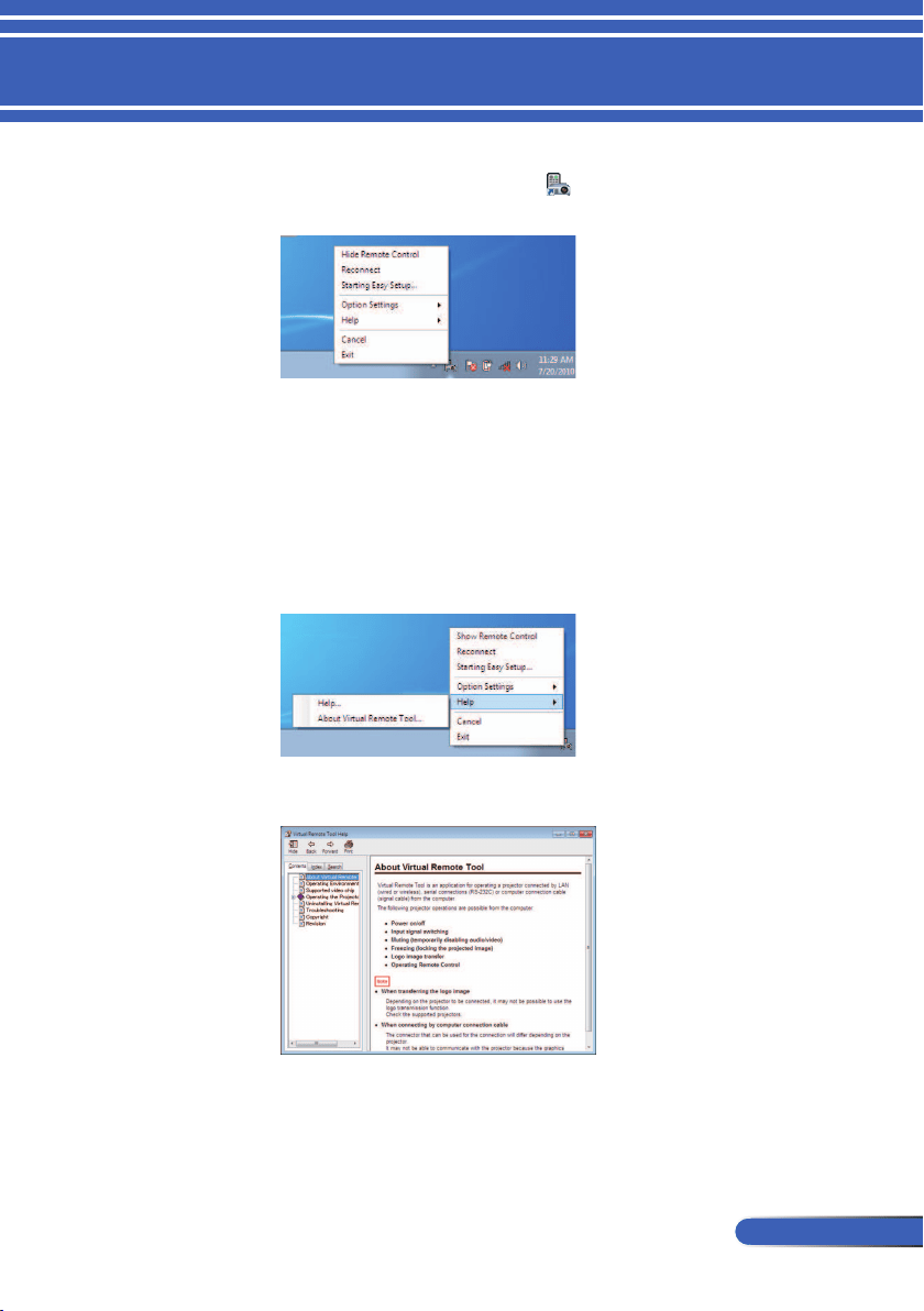
Exiting Virtual Remote Tool
1 Click the Virtual Remote Tool icon
on the Taskbar.
The pop-up menu will be displayed.
2 Click “Exit”.
The Virtual Remote Tool will be closed.
Viewing the help le of Virtual Remote Tool
Displaying the help le using the taskbar
1 Click the Virtual Remote Tool icon on the taskbar when Virtual Remote
Tool is running.
The pop-up menu will be displayed.
2 Click “Help”.
The Help screen will be displayed
Displaying the help le using the Start Menu.
Click “Start” -> “All programs” or “Programs” -> “NEC Projector
User Supportware” -> “Virtual Remote Tool” and then “Virtual
Remote Tool Help” in this order.
The Help screen will be displayed.
20
English ...
Introduction
Controlling the Projector over a LAN
[Using on Windows]
Using the utility software “PC Control Utility Pro 4” that you
can download from our web site
(http://www.nec-display.com/dl/en/index.html), the projector
can be controlled from a computer over a LAN.
Control Functions
Power On/Off, signal selection, picture freeze, picture mute,
audio mute, adjusting, error message notication, event sched-
ule.
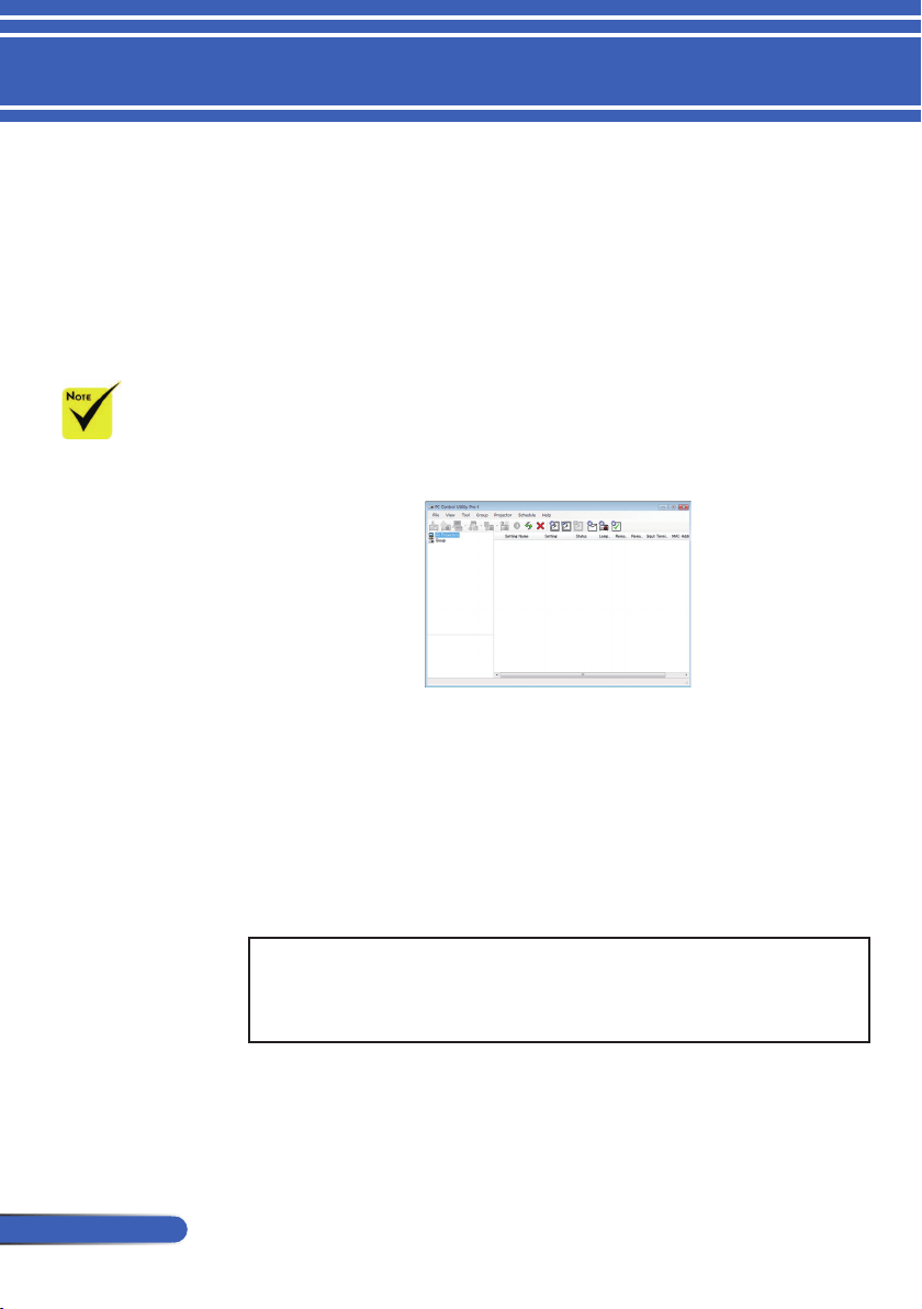
Screen of PC Control Utility Pro 4
This section provides an outline of preparation for use of PC Control
Utility Pro 4. For information on how to use PC Control Utility Pro 4,
see Help of PC Control Utility Pro 4. (-> page 22)
• Step 1: Install PC Control Utility Pro 4 on the computer. (-> page
21)
• Step 2: Connect the projector to a LAN. (-> page
22)
• Step 3: Start PC Control Utility Pro 4. (-> page
22)
TIP:
• PC Control Utility Pro 4 can be used with a serial connection.
• For update information on PC Control Utility Pro 4, visit our website:
http://www.nec-display.com/dl/en/index.html
When the projec-
tor is in the standby
condition, the Error
Alert function of PC
Control Utility Pro4 is
not available.
To make this function
available even in the
standby condition, use
the E-Mail Alert func-
tion of the projector.
(-> page 49)
(PC Control Utility Pro 4 for Windows/PC Control
Utility Pro 5 for Mac OS)
21
... English
Introduction
Step 1: Install PC Control Utility Pro 4 on the computer
• Supported OS - PC Control Utility Pro 4 will run on the following
operating systems.
Windows 8 *1, Windows 8 Pro *1, Windows 8 Enterprise *1,
Windows 7 Home Basic, Windows 7 Home Premium, Windows 7
Professional, Windows 7 Enterprise, Windows 7 Ultimate
Windows Vista Home Basic, Windows Vista Home Premium, Windows
Vista Business, Windows Vista Enterprise, Windows Vista Ultimate
Windows XP Home Edition *1, Windows XP Professional *1
*1: To run PC Control Utility Pro 4, “Microsoft .NET Framework Version
2.0” is required. The Microsoft .NET Framework Version is available from
Microsoft’s web page. Install the Microsoft .NET Framework Version 2.0, 3.0
or 3.5 on your computer.
1 Connect your computer to the Internet and download the updated PCCUP4
exe le from our web site (http://www.nec-display.com/dl/en/index.html).
2 Double-click the PCCUP4. exe icon.
The Installer will start and the Wizard screen will appear.
3 Click “Next”.
“END USER LICENSE AGREEMENT” screen will be displayed.
To install or unin-
stall the program, the
Windows user account
must have [Admin-
istrator] privilege
(Windows 8, Windows
7, Windows Vista and
Windows XP)
Exit all running
programs before
installation. If another
program is running,
the installation may
not be completed.
22
English ...
Introduction
Read “END USER LICENSE AGREEMENT” carefully.
4 If you agree, click “I accept the terms in the license agreement”
and then
click “Next”.
Follow the instructions on the installer screens to complete the
installation.
TIP:Uninstalling PC Control Utility Pro 4
• To uninstall PC Control Utility Pro 4, do the same procedures stated as in
“Uninstalling Virtual Remote Tool”. Read “Virtual Remote Tool” as “PC
Control Utility Pro 4” (-> page 19)
Step 2: Connect the projector to a LAN
Connect the projector to the LAN by following the instructions
in “Connecting the Projector” on page 25 and “How to use web
browser to control your projector” in pages 49-50.
Step 3: Start PC Control Utility Pro 4
Click “Start” -> “All programs” or “Programs” -> “NEC Projector
User Supportware” -> “PC Control Utility Pro 4” -> “PC Control
Utility Pro 4”.
TIP: Viewing the Help of PC Control Utility Pro 4Viewing the Help of PC Control Utility Pro 4
• Displaying the Help le of PC Control Utility Pro 4 while it is running.
Click “Help (H)” -> “Help (H)” of window of PC Control Utility Pro 4 in
this order.
The pop-up menu will be displayed.
• Displaying the help le using the Start Menu.
Click “Start” -> “All programs” or “Programs” -> “NEC Projector User
Supportware” -> “PC Control Utility Pro 4” -> “PC Control Utility Pro 4
Help”.
The Help screen will be displayed.
For the Schedule
function of the PC
Control utility Pro 4 to
work, you must have
your computer run-
ning and not in stand-
by/sleep mode. Select
“Power Options” from
the “Control Panel” in
Windows and disable
its standby/sleep
mode before running
the scheduler.
[Example] For Win-
dows 7:
Select “Control
Panel” -> “System and
Security” -> “Power
Options” -> “Change
when the computer
sleeps” -> “Put the
computer to sleep” ->
”Never”.
When “Power-
Saving” is selected for
“Standby Mode” from
the menu, the projector
cannot be controlled
via the serial cable or
network (wired LAN)
connection.
The projector
does not support the
LAN automatic search
feature of PC Control
Utility Pro 4. To con-
nect the projector,
register an IP address
manually.
PC Control Utility Pro 5 for Mac OS
Step 1: Install PC Control Utility Pro 5 on the computer
1 Connect your computer to the Internet and visit our website (http://www.
nec-display.com/dl/en/index.html).
2 Download the updated PC Control Utility Pro 5 from our website.
3 In Finder, control-click (“control” + click) or right click the PC Control
Utility Pro 5.mpkg.
4 Select “Open” from the top of contextual menu that appears.
23
... English
Introduction
5 Click “Open” in the dialog box. If prompted, enter an administrator name
and password.
The installer will start.
6 Click “Next”.
“END USER LICENSE AGREEMENT” screen will be displayed.
7 Read “END USER LICENSE AGREEMENT” and click “Next”.
The conrmation window will be displayed.
8 Click “I accept the terms in the license agreement”.
Follow the instructions on the installer screens to complete the installation.
Step 2: Connect the projector to a LAN
Connect the projector to the LAN by following the instructions in “Connect-
ing the Projector” (-> page 25)
Step 3: Start PC Control Utility Pro 5
1. Open your Applications folder in Mac OS.
2. Click the “PC Control Utility Pro 5” folder.
3. Click the “PC Control Utility Pro 5” icon.
PC Control Utility Pro 5 will start.
TIP: Viewing the Help of PC Control Utility Pro 5
• Displaying the Help le of PC Control Utility Pro 5 while it is running.
• From the menu bar, click “Help” → “Help” in this order.
The Help screen will be displayed
• Displaying the Help using the Dock
1. Open “Application Folder” in Mac OS.
2. Click the “PC Control Utility Pro 5” folder.
3. Click the “PC Control Utility Pro 5 Help” icon.
The Help screen will be displayed.
TIP: Uninstalling a software program
1. Put the “PC Control Utility Pro 5” folder to the Trash icon.
2. Put the conguration le of PC Control Utility Pro 5 to the Trash icon.
• The conguration le of PC Control Utility Pro 5 is located in “/Users/
<your user name>/Application Data/NEC Projector User Supportware/
PC Control Utility Pro 5”.
For the Schedule
function of the PC
Control utility Pro 5 to
work, you must have
your computer run-
ning and not in sleep
mode. Select “En-
ergy Saver” from the
“System Preferences”
in Mac and disable its
sleep mode before run-
ning the scheduler.
When [POWER-
SAVING] is se-
lected for [STANDBY
MODE] from the
menu, the projector
cannot be turned on
via the network.

24
English ...
Introduction
Viewing 3D Images
The projector provides 3D images to a user wearing commercially
available LCD shutter eyeglasses.
CAUTION
Health precautions
Before viewing, be sure to read health care precautions that may be found
in the user’s manual included with your LCD shutter eyeglasses or your 3D
compatible content such as DVDs, video games, computer’s video les and
the like.
To avoid any adverse symptoms, heed the following:
- Do not use LCD shutter eyeglasses for viewing any material other than 3D
images.
- Allow a distance of 2 m/7 feet or greater between the screen and a user.
Viewing 3D images from too close a distance can strain your eyes.
Avoid viewing 3D images for a prolonged period of time. Take a break of 15
minutes or longer after every hour of viewing.
- If you or any member of your family has a history of light-sensitive sei-
zures, consult a doctor before viewing 3D images.
- While viewing 3D images, if you get sick such as nausea, dizziness, queasi-
ness, headache, eyestrain, blurry vision, convulsions, and numbness, stop
viewing them. If symptoms still persist, consult a doctor.
- View 3D images from the front of the screen. Viewing from an angle may
cause fatigue or eyestrain.
LCD shutter eyeglasses
• Use commercially available 3D eyeglasses which meet the following
requirements:
- DLP
®
Link compatible
- Support vertical refresh rate up to 144 Hz.
Steps for viewing 3D images on the projector
1. Connect the projector to your video equipment.
2. Turn on the projector, display the on-screen menu.
3. Select [3D SETTINGS] from [SCREEN] tab and then select [ON] for
[3D].
- Set for [3D INVERT] and [3D STRUCTURE] as necessary. (see page
41)
4. Play your 3D compatible content and use the projector to display the
image.
5. Put on your LCD shutter eyeglasses to view 3D images.
Also refer to the user’s manual accompanied with your LCD shutter
eyeglasses for more information.
25
... English
Installation
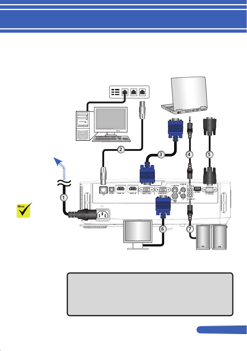
Connecting the Projector
1.............................................................................................Power cord (supplied)
2..................................................................................................................LAN cable
3........................................................................ Computer cable (VGA) (supplied)
4...........................................................................................................Audio in cable
5................................................................................................................RS232 cable
6...........................................................................................................VGA out cable
7........................................................................................................ Audio out cable
Make sure that the
power plug is fully
inserted into both the
projector AC inlet and
the wall outlet.
Connect to Computer/Notebook
E62405SP
R
To the wall outlet
Audio Output
Hub
Server
1
2
3 4 5
6 7
26
English ...
Installation
Due to the differ-
ence in applications
for each country, some
regions may have
different accessories.
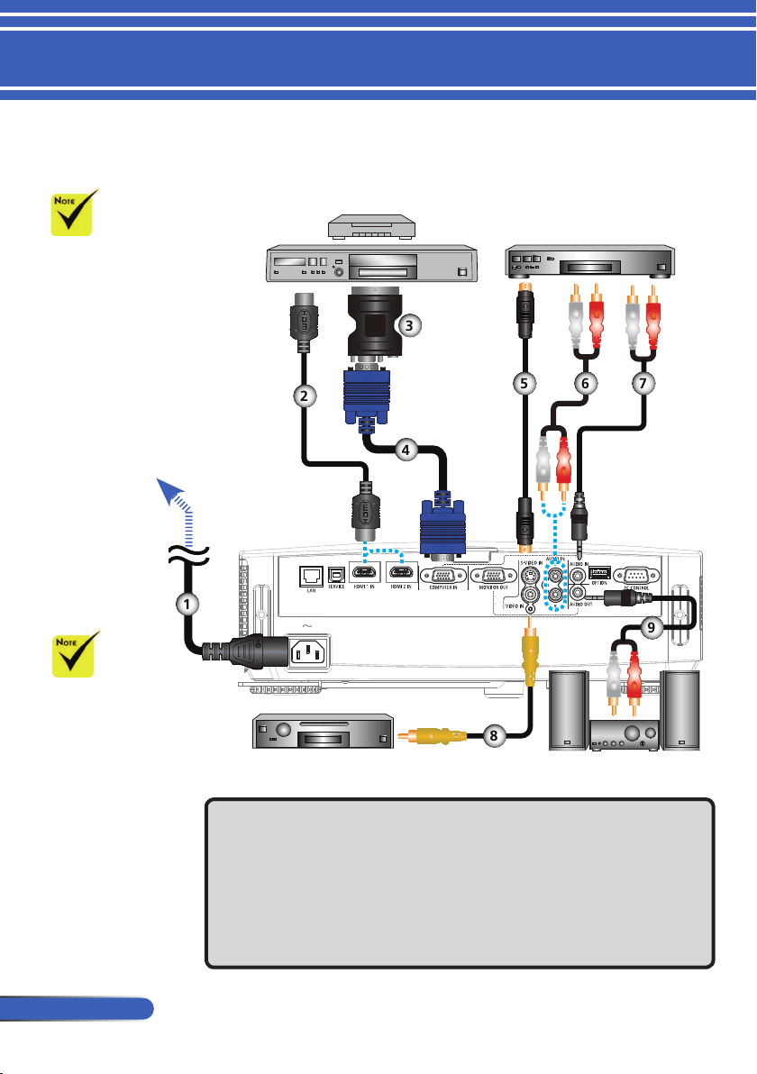
Connect to Video Sources
1.............................................................................................Power cord (supplied)
2...............................................................................................................HDMI cable
3.............................................................................................SCART/VGA adaptor
4........................................................................ Computer cable (VGA) (supplied)
5............................................................................................................ S-Video cable
6...........................................................................................................Audio in cable
7...........................................................................................................Audio in cable
8............................................................................................ Composite video cable
9........................................................................................................ Audio out cable
Make sure that the
power plug is fully
inserted into both the
projector AC inlet and
the wall outlet.
E62405SP
R
Video Output
S-Video Output
DVD Player, Blu-ray Player,
Set-top Box, HDTV receiver
Audio Output
To the wall outlet
HDMI cable: Use High Speed HDMI
®
Cable.
1
2
3
4
5
6 7
8
9
27
... English
Installation
Powering On/Off the Projector
Turn on the projector
rst and then the signal
sources.
or
(*)When “Power-
Saving” is selected for
“Standby Mode”,the
Power LED will turn
red; when “Normal” is
selected for “Standby
Mode”, the Power LED
will turn orange.
1
2
Lens Cover
Power
When you rst
turn on the projec-
tor, you will get the
Startup menu. This
menu gives you the
opportunity to select
the menu languages.
To select the language,
use the , ,
, or button on the
remote control. Select
your language. Refer
to Language on page
42.
While the POWER
indicator is blinking
blue in short cycles,
the power cannot be
turned off by using the
power button.
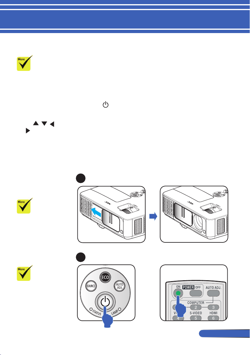
Powering On the Projector
1. Slide the lens cover.
2. Ensure that the power cord and signal cable are securely
connected. The Power indicator will turn red. (*)
3. Turn on the projector by pressing “POWER” on the remote
control or on the control panel. The Power indicator
will ash blue. The startup screen (NEC logo) will be dis-
played. and the Power indicator will turn steady blue.
4. Turn on your source (computer, notebook, video player,etc.)
The projector will detect your source automatically.
If you connect multiple sources at the same time, use the
“SOURCE” button on the control panel or use “COMPUTER
1”, “VIDEO”, “HDMI” on the remote control to switch in-
puts.

28
English ...
Installation
Powering Off the Projector
1. Press the “POWER OFF” button on the remote control or the
button on the control panel to turn off the projector lamp,
you will see a message as below on the on-screen display.
2. Press the “POWER OFF” button again to con rm.
3. Disconnect the power cord from the electrical outlet and the
projector. If you disconnect the power cord while viewing
the picture and connect the power cord again, wait for at
least one second until you connect the power cord again.
While the POWER
indicator is blinking
blue in short cycles,
the power cannot be
turned off by using
the power button.
29
... English
Installation
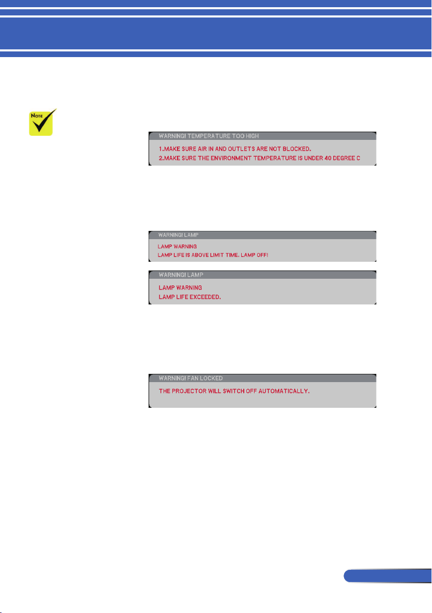
Warning Indicator
When the “STATUS” LED indicator ashes red, it indicates
the projector has overheated. The projector will automati-
cally shut itself down.
When the “LAMP” LED indicator turns red and the message
below displays on-screen, the projector has detected that the
lamp is approaching its end of life. When you see this mes-
sage, change the lamp as soon as possible.
When the “STATUS” LED indicator ashes red and the
message below displays on-screen, it indicates the fan failed.
Stop using the projector and disconnect the power cord from
the electrical outlet, then contact your local dealer or our
service center.
For more information
on STATUS LED, refer
to page 58.
30
English ...
Installation
2
3
3
1
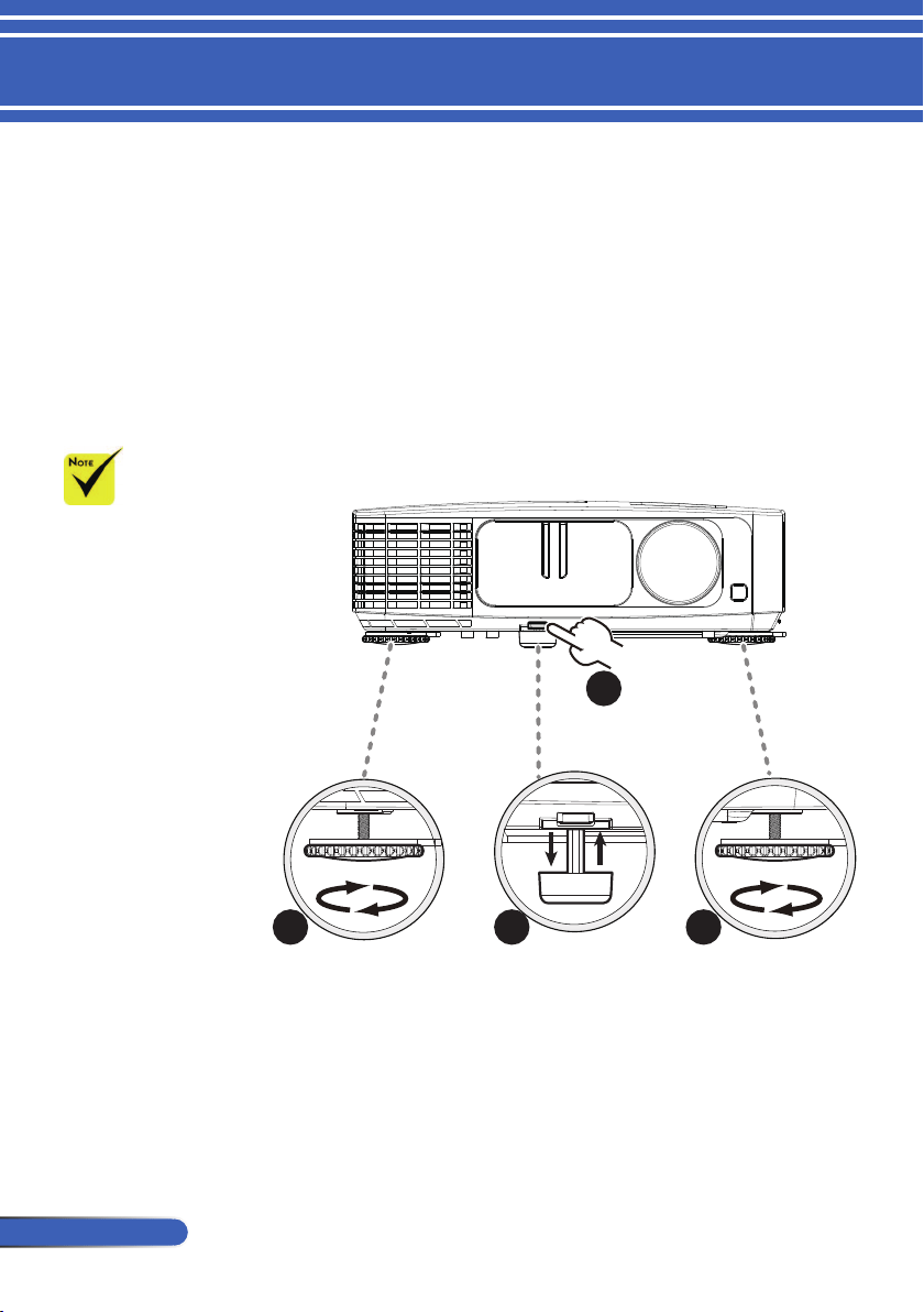
Adjusting the Projected Image
Adjusting the Height of Projector Image
The projector is equipped with tilt foot and rear feet to raise and
lower the image to ll the screen.
1. Press the tilt foot release. u
Raise or lower the image to the desired height angle, then
release the button to lock the tilt foot into position. v
2. Rotate the rear feet counter clockwise to raise the projector
or clockwise to lower it. w
2
1
3 3
By using the tilt
foot the projector can
be raised up to an
angle of 5 degrees.
Tilt foot
release button
Rear foot Tilt foot Rear foot
31
... English
Installation
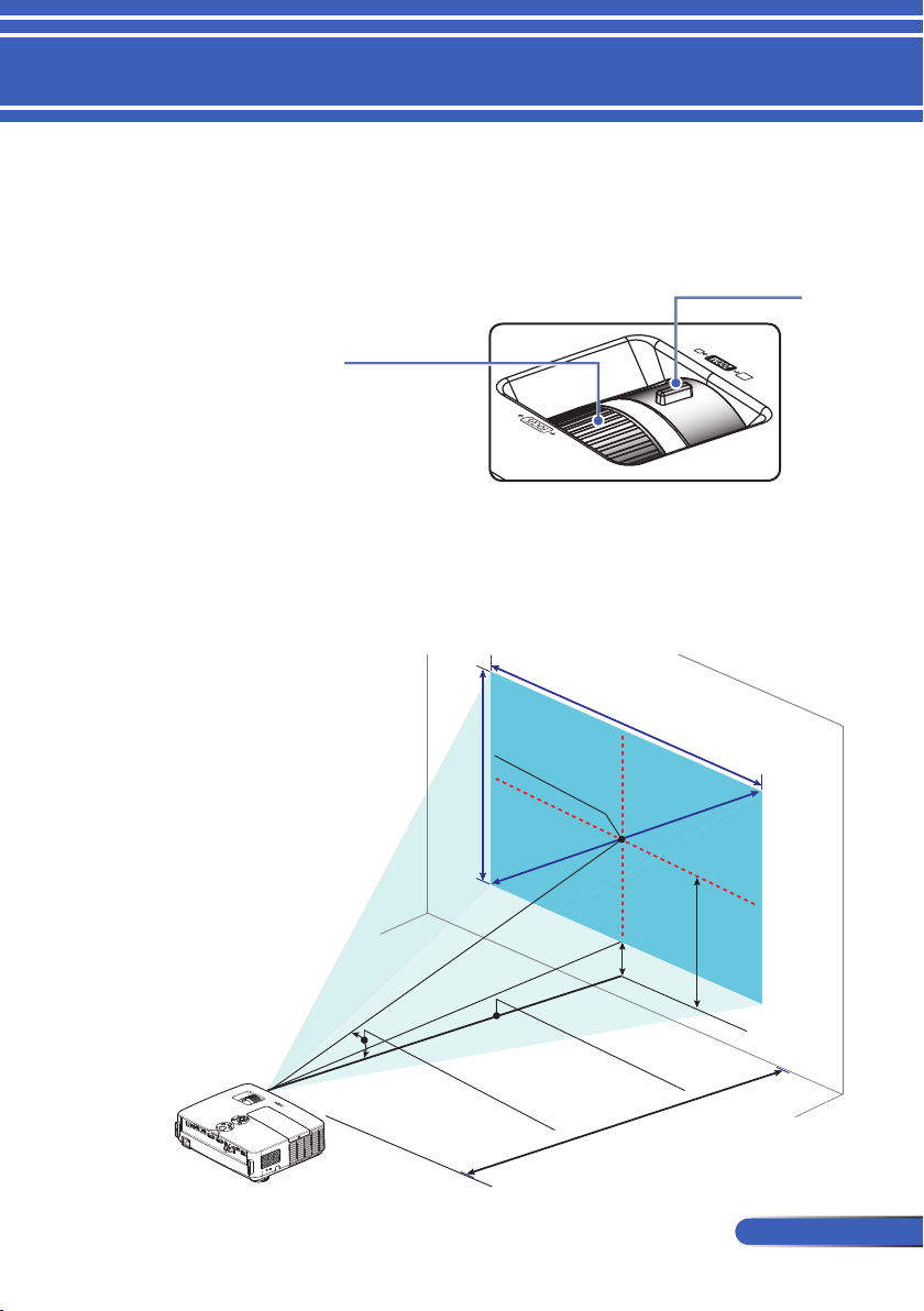
Adjusting the Projector Zoom/Focus
You may turn the zoom ring to zoom in or out. To focus the im-
age, rotate the focus ring until the image is clear. The projector
will focus at distances from 32 to 474 inch (0.82 to 12.0 meters)
with mechanical travel.
Zoom Lever
Focus Ring
Adjusting Projection Image Size
Screen Width
Screen Hight
Screen Center
Screen Diagonal (A)
Throw Angle (α)
Lens Center
(
D
)
(B)
Throw Distance (C)
32
English ...
Installation
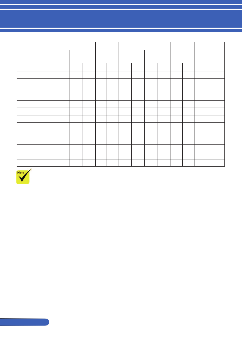
Screen Size (B) (C) (D) (α)
Diagonal
(A)
Width Height
Wide Tele Wide Tele
inch mm inch mm inch mm inch mm inch mm inch mm inch mm degree degree
23 584 20 509 11 286 7 189 32 815 55 1385 2 46 13.1 7.8
30 762 26 664 15 374 10 247 42 1063 70 1806 2 60 13.1 7.8
40 1016 35 886 20 498 13 329 56 1417 95 2409 3 80 13.1 7.8
60 1524 52 1328 29 747 19 493 84 2125 142 3613 5 120 13.1 7.8
72 1829 63 1594 35 897 23 592 100 2550 171 4336 6 143 13.1 7.8
80 2032 70 1771 39 996 26 657 112 2834 190 4817 6 159 13.1 7.8
84 2134 73 1860 41 1046 27 690 117 2975 199 5058 7 167 13.1 7.8
90 2286 78 1992 44 1121 29 740 126 3188 213 5419 7 179 13.1 7.8
100 2540 87 2214 49 1245 32 822 139 3542 237 6022 8 199 13.1 7.8
120 3048 105 2657 59 1494 39 986 167 4250 284 7226 9 239 13.1 7.8
150 3810 131 3321 74 1868 49 1233 209 5313 356 9032 12 299 13.1 7.8
180 4572 157 3985 88 2241 58 1479 251 6376 427 10839 14 359 13.1 7.8
200 5080 174 4428 98 2491 65 1644 279 7087 474 12043 16 398 13.1 7.8
This graph is for user’s reference only.
The values in the table are design values and may vary.
B=Vertical distance between lens center and screen center
C=Throw distance
D=Vertical distance between lens center and bottom of screen (top of screen
for desktop)
α=Throw angle
33
... English
User Controls
The Projector has a multilingual On Screen Display that allows
you to make image adjustments and change a variety of set-
tings.
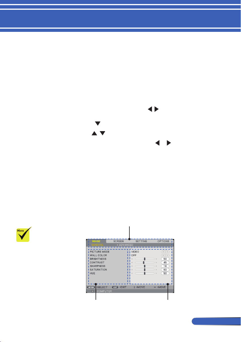
How to operate
1. To open the OSD, press the MENU button on the Remote Control.
2. When OSD is displayed, use the buttons to select any item
in the main menu. While making a selection on a particular page,
press the button to enter sub menu.
3. Use the buttons to select the desired item in the sub menu
and adjust the settings by using the or button.
4. Select the desired item in the sub menu and press the ENTER
button to enter another sub menu. Press the MENU button to close
the sub menu after adjustment.
5. After adjusting the settings, press the MENU or EXIT button go
back to the main menu.
6. To exit, press the MENU button again. The OSD will be closed and
the projector will automatically save the new settings.
On Screen Display
Main Menu
Sub Menu
If no button operation
is made for 30 seconds,
the OSD will be closed
automatically.
Setting
34
English ...
User Controls
Menu Tree
Main Menu Sub Menu Settings
IMAGE
GENERAL
PICTURE MODE
WALL COLOR
BRIGHTNESS 0 to 100
CONTRAST 0 to 100
SHARPNESS 0 to 31
SATURATION 0 to 100
HUE 0 to 100
ADVANCED
GAMMA
BrilliantColor™ 0 to 10
COLOR TEMP. LOW / MEDIUM / HIGH
DYNAMIC CONTRAST OFF/ ON
COLOR
COLOR SPACE AUTO / RGB / YUV
SCREEN
GENERAL
ASPECT RATIO
OVERSCAN 0[%], 5[%], 10[%]
V KEYSTONE -40 to 40
3D SETTING
3D OFF / ON
3D INVERT OFF / ON
3D STRUCTURE
SETTING
GENERAL
LANGUAGE
ORIENTATION
REMOTE SENSOR
HDMI SETTINGS
HDMI1 VIDEO LEVEL / AUDIO SELECT
HDMI2 VIDEO LEVEL / AUDIO SELECT
MUTE OFF / ON
VOLUME 0 to 31
SIGNAL
PHASE
CLOCK
H. POSITION
V. POSITION
PRESENTATION / HIGH-BRIGHT /
VIDEO / MOVIE / sRGB / BLACKBOARD /
USER1 / USER2
OFF / RED / GREEN / BLUE / CYAN /
MEGENTA / YELLOW
FILM / VIDEO / GRAPHICS / PC /
BLACKBOARD
RED GAIN / GREEN GAIN / BLUE GAIN /
CYAN GAIN / MAGENTA GAIN / YELLOW
GAIN / RED BIAS / GREEN BIAS / BLUE
BIAS / RESET
4:3 / 16:9 / 16:10 / 15:9 / 5:4 / NATIVE /
AUTO
AUTO / FRAME PACKING / TOP-AND-
BOTTOM / SIDE-BY-SIDE / FRAME
SEQUENTIAL
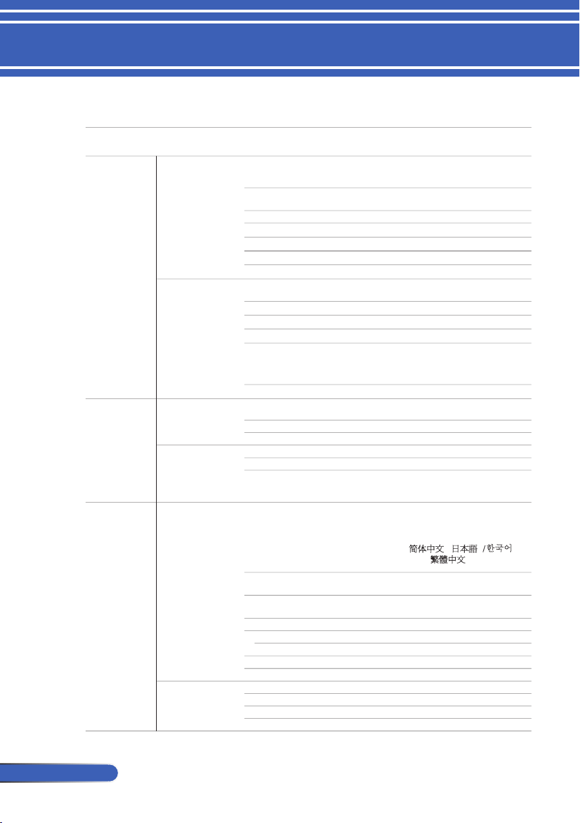
ENGLISH / DEUTSCH / FRANÇAIS /
ITALIANO / ESPAÑOL / PORTUGUÊS /
POLSKI / ɊɍɋɋɄɂɃ / SVENSKA /
NORSK / ǼȁȁǾȃǿȀDZ / MAGYAR /
ýEŠTINAʳ/ 亞
խ֮ʳ/ ֲء!0ᾂ᱑ /
TÜRKÇE / ϲΑήϋ /
᧯խ֮ʳ/ INDONESIA
DESKTOP FRONT/DESKTOP
REAR/CEILING FRONT/CEILING REAR
FRONT/BACK /
FRONT / BACK

35
... English
User Controls
Main Menu Sub Menu Settings
SETTING
ADVANCED
LOGO OFF / ON
PC CONTROL MODE PC CONTROL / LAN
NETWORK
NETWORK STATE DISCONNECT / CONNECT
DHCP OFF / ON
IP ADDRESS 0.0.0.0
SUBNET MASK 0.0.0.0
GATEWAY 0.0.0.0
DNS 0.0.0.0
APPLY
CLOSED CAPTION
SECURITY
SECURITY OFF / ON
SECURITY TIMER MONTH / DAY / HOUR
CHANGE PASSWORD ʳ
OPTIONS
GENERAL
INPUT SEARCH OFF / ON
INPUT
FAN MODE AUTO / HIGH SPEED
INFORMATION HIDE OFF / ON
BACKGROUND COLOR BLACK / BLUE
RESET NO / YES
LAMP LIFE REMAINING 100% ..1%
LAMP HOURS USED
FILTER HOURS USED
ECO MODE OFF / ON
LAMP LIFE REMINDER OFF / ON
FILTER USAGE HOURS
CLEAR LAMP HOURS
CLEAR FILTER HOURS
INFORMATION
MODEL NO.
SERIAL NUMBER
SOURCE
RESOLUTION
SOFTWARE VERSION
ADVANCED
STANDBY MODE POWER-SAVING / NORMAL
DIRECT POWER ON OFF / ON
AUTO POWER OFF (MIN.) 0 to 180
OFF TIMER (MIN.) 0 to 995
CONTROL PANEL LOCK OFF / ON
OFF / CC1 / CC2 / CC3 / CC4 / T1 / T2 /
T3 / T4
COMPUTER / HDMI1 / HDMI2 / VIDEO /
S-VIDEO
LAMP/FILTER
SETTINGS
36
English ...
User Controls
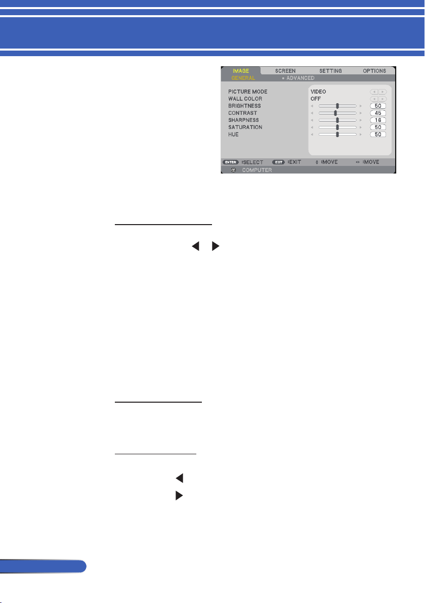
PICTURE MODE
There are many factory presets optimized for various types of
images. Use the or button to select the item.
PRESENTATION: For computer or notebook.
HIGH-BRIGHT: Maximum brightness from PC input.
VIDEO: This mode is recommended for typical TV program
viewing.
MOVIE: For home theater.
sRGB: Standardized accurate color.
BLACKBOARD: This mode should be selected to achieve
optimum color settings when projecting onto a blackboard
(green).
USER1/USER2: Memorize user’s settings.
WALL COLOR
Use this function to choose a proper color according to the wall. It
will compensate the color deviation due to the wall color to show
the correct image tone.
BRIGHTNESS
Adjust the brightness of the image.
Press the button to darken image.
Press the button to lighten the image.
IMAGE |
GENERAL
37
... English
User Controls
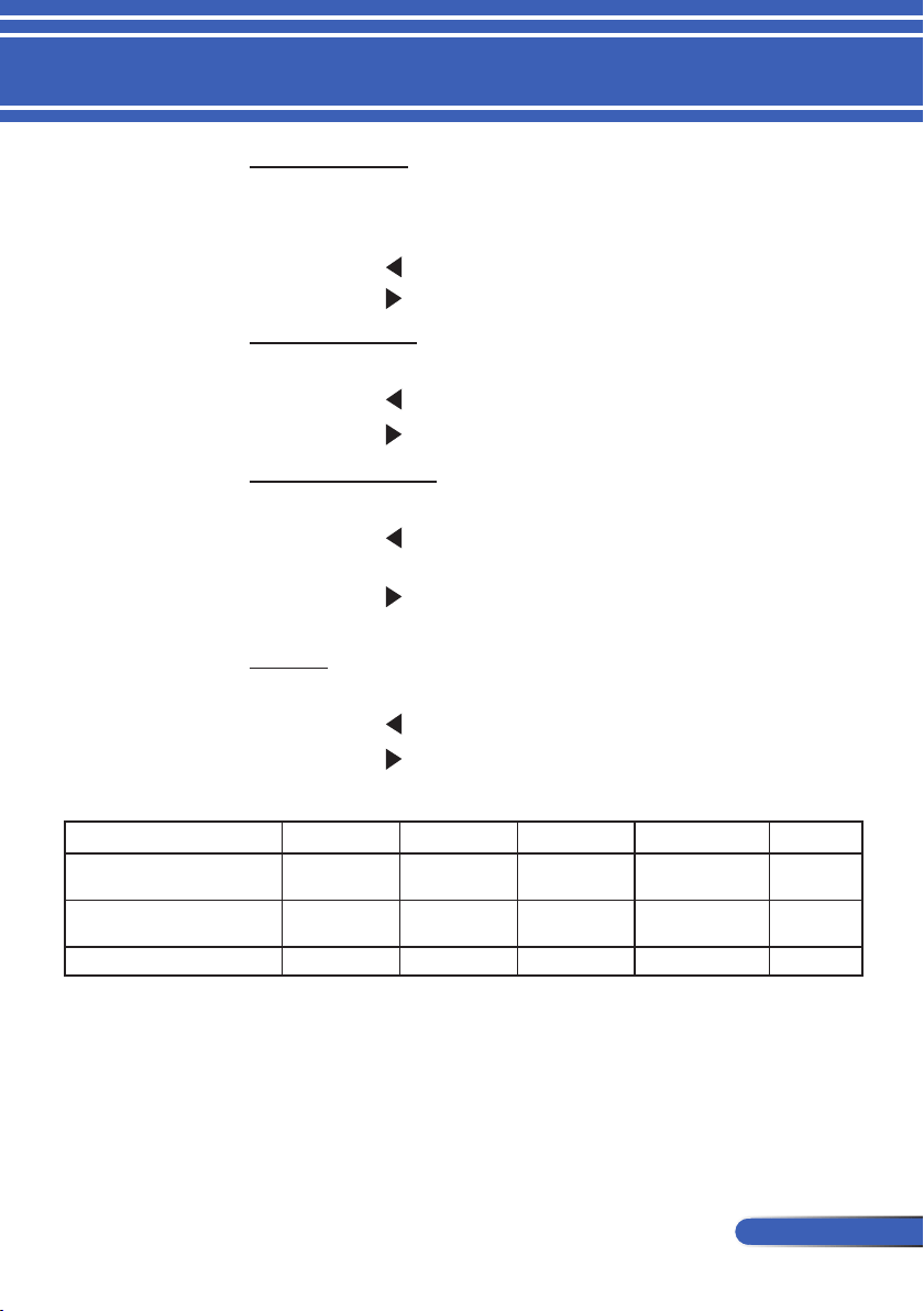
CONTRAST
The contrast controls the degree of difference between the lightest
and darkest parts of the picture. Adjusting the contrast changes the
amount of black and white in the image.
Press the button to decrease the contrast.
Press the button to increase the contrast.
SHARPNESS
Adjust the sharpness of the image.
Press the button to decrease the sharpness.
Press the button to increase the sharpness.
SATURATION
Adjust a video image from black and white to fully saturated color.
Press the button to decrease the amount of saturation in the
image.
Press the button to increase the amount of saturation in the
image.
HUE
Adjust the color balance of red and green.
Press the button to increase the amount of green in the image.
Press the button to increase the amount of red in the image.
Input signal
BRIGHTNESS CONTRAST SHARPNESS SATURATION HUE
COMPUTER/
HDMI (RGB)
YES YES YES NO NO
COMPUTER/
HDMI (COMPONENT)
YES YES YES YES YES
VIDEO/S-VIDEO YES YES YES YES YES
Yes=Adjustable, No=Not adjustable
38
English ...
User Controls
The Color Temp is
not available when
“HIGH-BRIGHT”
or “sRGB” is
selected for “PIC-
TURE MODE”.
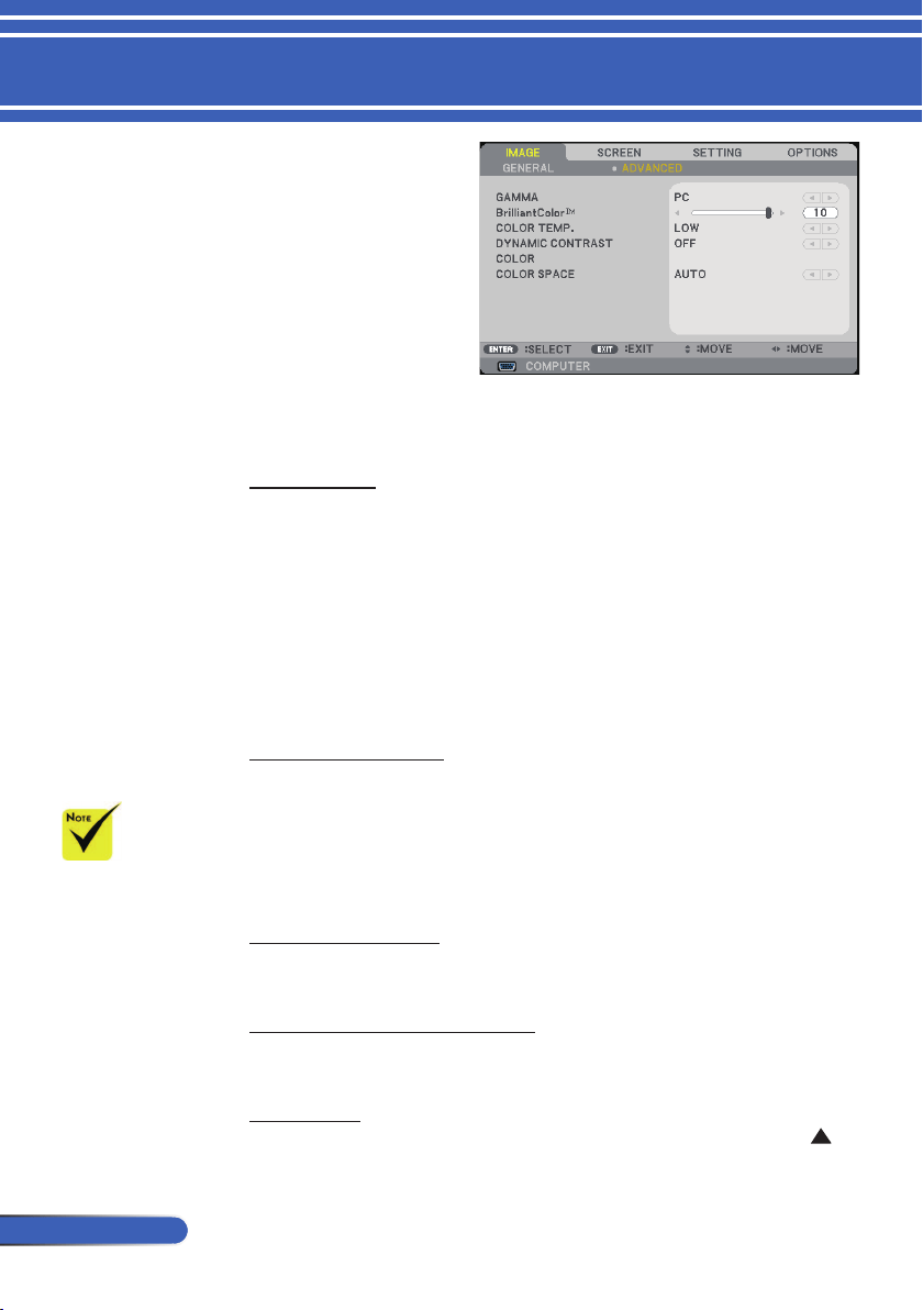
GAMMA
This allows you to choose a gamma table that has been ne-tuned
to bring out the best image quality for the input.
FILM: for home theater.
VIDEO: for video or TV source.
GRAPHICS: for image source.
PC: for PC or computer source.
BLACKBOARD: for displaying on the blackboard.
BrilliantColor™
This adjustable item utilizes a new color-processing algorithm
and system level enhancements to enable higher brightness while
providing true, more vibrant colors. The range is from “0” to “10”.
If you prefer a stronger enhanced image, adjust toward the maxi-
mum setting. For a smoother, more natural image, adjust toward
the minimum setting.
COLOR TEMP.
Adjust the color temperature. At higher temperature, the screen
looks colder; at lower temperature, the screen looks warmer.
DYNAMIC CONTRAST
Turning this item on allows the contrast ratio to be adjusted to the
proper level.
COLOR
Press ENTER into the next menu as below and then use the
or
IMAGE |
ADVANCED

39
... English
User Controls
button to select item.
RED GAIN/GREEN GAIN/BLUE GAIN/RED BIAS/GREEN
BIAS/BLUE BIAS/CYAN GAIN/MAGENTA GAIN/
YELLOW GAIN: Use the or button to select RED, GREEN,
BLUE, CYAN, MAGENTA AND YELLOW COLORS.
RESET: Choose “YES” to return the factory default settings for
color adjustments.
COLOR SPACE
Select an appropriate color matrix type from AUTO, RGB or YUV.
40
English ...
User Controls
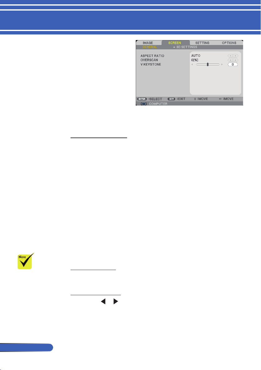
ASPECT RATIO
Use this function to choose your desired aspect ratio.
4:3: This format is for 4×3 input sources.
16:9: This format is for 16×9 input sources, like HDTV and DVD
enhanced for Wide screen TV.
16:10: This format is for 16×10 input sources, like widescreen
laptops.
15:9: This format is for non-16x9, letterbox source and for users
who use external 16x9 lens to display 1.67:1 aspect ratio using
full resolution.
5:4: This format is for 5×4 input sources.
NATIVE: This format displays the original image without any
scaling.
AUTO: Automatically selects the appropriate display format.
OVERSCAN
Overscan function removes the noise in a video image. Overscan the
image to remove video encoding noise on the edge of video source.
V KEYSTONE
Press the
or button to adjust image distortion vertically. If
the image looks trapezoidal, this option can help make the image
rectangular.
Each I/O has
different setting of
“OVERSCAN”.
SCREEN |
GENERAL
41
... English
User Controls
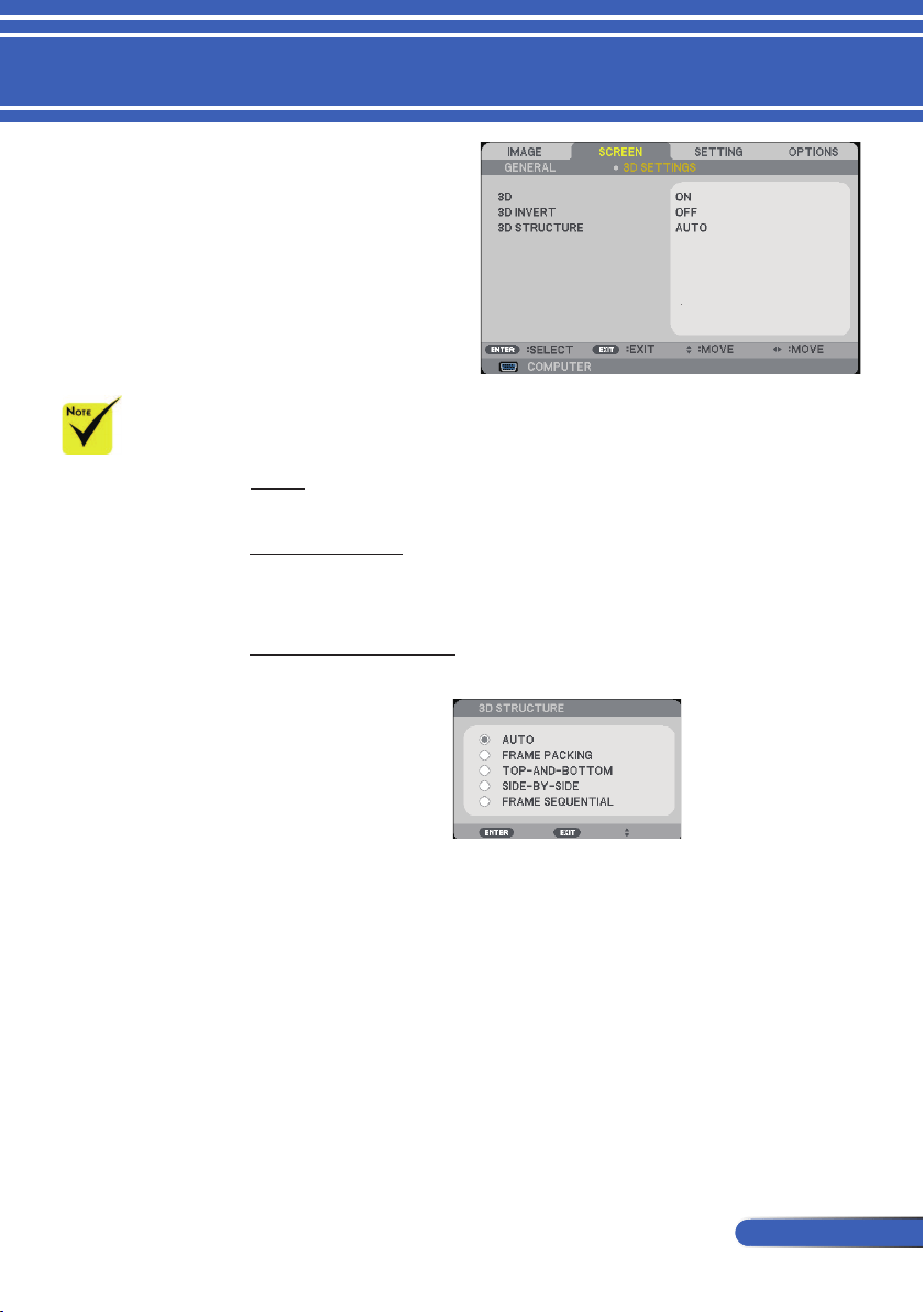
TIP: 3D supported signal
• For PC Signal :
1024x768@120Hz, 1024x768@60Hz,
1280x720@120Hz,1280x720@60Hz
1280x800@120Hz,1280x800@60Hz
• For Video Signal :
480i@60Hz
• For HDMI Signal :
720p, 1080p @Frame Packing
720p,1080i/p @Top and Bottom
720p, 1080i/p @Side by Side (Half)
3D
Choose “ON” to turn this item on for 3D images.
(default: OFF)
3D INVERT
Choose “ON” to invert left and right frame contents.
Choose “OFF” for default frame contents.
3D STRUCTURE
Adjust the 3D format to display 3D content correctly.
“3D INVERT”
and “3D
STRUCTURE”only
available when 3D
is enabled.
Compatible 3D
source, 3D content
and active shutter
glasses are required
for 3D viewing.
SCREEN |
3D SETTING
42
English ...
User Controls
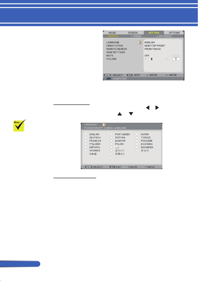
LANGUAGE
Choose the multilingual OSD menu. Press the
or button into
the sub menu and then use the or button to select your
preferred language. Press ENTER to nalize the selection.
ORIENTATION
DESKTOP FRONT:
This is the default selection. The image is projected straight on
the screen.
DESKTOP REAR:
When selected, the image will appear reversed.
CEILING FRONT:
When selected, the image will turn upside down.
CEILING REAR
When selected, the image will appear reversed in upside down
position.
DESKTOP-REAR
and CEILING-
REAR are to
be used with
a translucent
screen.
SETTING |
GENERAL
43
... English
User Controls
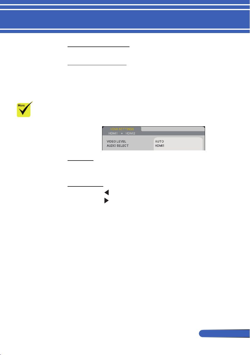
REMOTE SENSOR
Choose the remote sensor location.
HDMI SETTINGS
Use this feature to set HDMI1/HDMI2
VIDEO LEVEL: Select “AUTO” to automatically detect video
level. If automatic detection may not work well, select “NOR-
MAL” to disable the “ENHANCED” feature of your HDMI
equipment or select “ENHANCED” to improve image contrast
and increase detail in the dark areas.
AUDIO SELECT: Use this function to select the audio souce
from “HDMI1”, “HDMI2”or “COMPUTER”.
MUTE
Choose “ON” to turn mute on.
Choose “OFF” to turn mute off.
VOLUME
Press the button to decrease the volume.
Press the button to increase the volume.
“HDMI SETTING”
is only supported
under HDMI
source.
44
English ...
User Controls
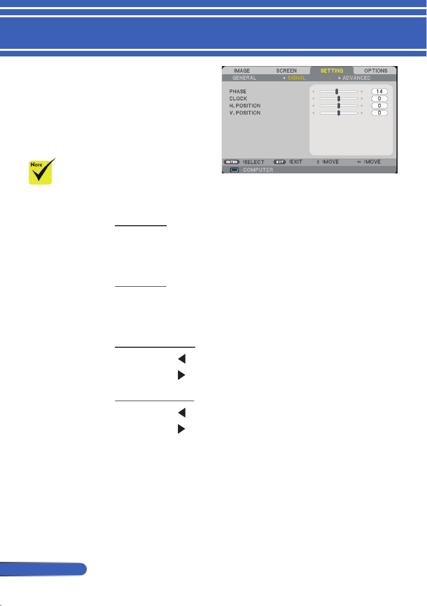
PHASE
Synchronize the signal timing of the display with the graphic card.
If the image appears to be unstable or ickers, use this function to
correct it.
CLOCK
Change the display data frequency to match the frequency of
your computer’s graphic card. Use this function only if the image
appears to icker vertically.
H. POSITION
Press the button to move the image left.
Press the button to move the image right.
V. POSITION
Press the button to move the image down.
Press the button to move the image up.
“SIGNAL” is
only supported in
Analog VGA (RGB)
signal.
SETTING |
SIGNAL
45
... English
User Controls
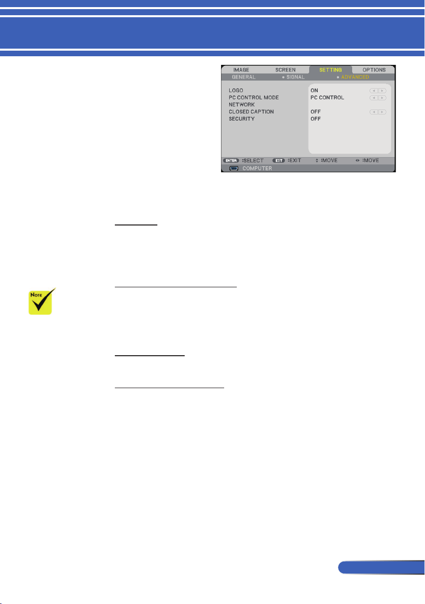
LOGO
Use this function to display the startup screen (NEC logo).
ON: Displays the NEC logo.
OFF: Not display the NEC logo.
PC CONTROL MODE
PC CONTROL: Allow PC control of an individual projector.
(default setting)
LAN: Allow projector control via web browser (Internet
Explorer) using the network.
NETWORK
Refer to pages 48-50.
CLOSED CAPTION
Use this function to enable close caption and activate the closed
caption menu. Select an appropriate closed captions option: OFF,
CC1, CC2, CC3, CC4, T1, T2, T3 and T4.
When “POWER-
SAVING” is select-
ed for “STANDBY
MODE” from the
menu, the projec-
tor cannot be con-
trolled in standby
mode from exter-
nal equipment.
SETTING |
ADVANCED
46
English ...
User Controls
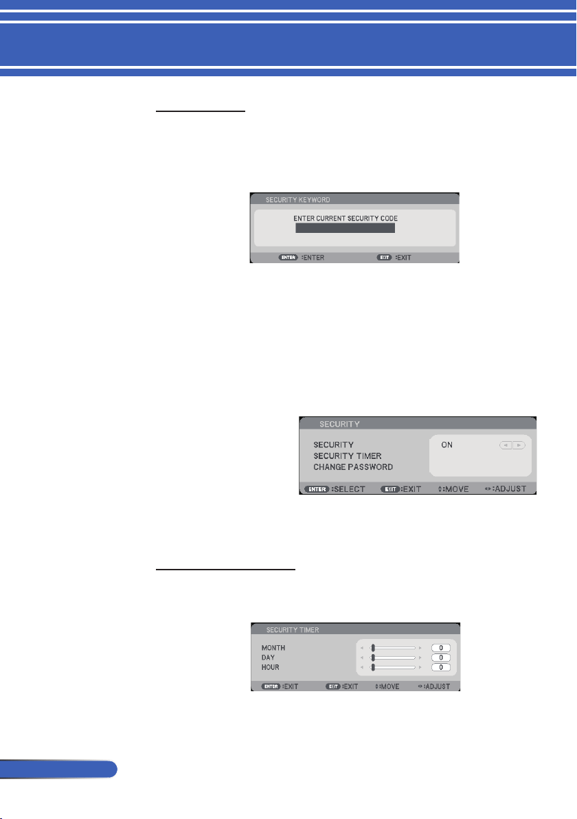
SECURITY TIMER
Use this function to set how long (MONTH/DAY/HOUR) the
projector can be used. Once this time has elapsed you will be
requested to enter your password again.
SETTING |
ADVANCED |
SECURITY
SECURITY
OFF: Choose “OFF” to be able to switch on the projector with-
out password veri cation.
ON: Choose “ON” to use security veri cation when turning on
the projector.
■ First Time:
1. The Password is 4 digits, default value is “1234”. ( rst time)
2. Use number buttons on the remote to enter your password,
and then press ENTER to con rm your password.
47
... English
User Controls
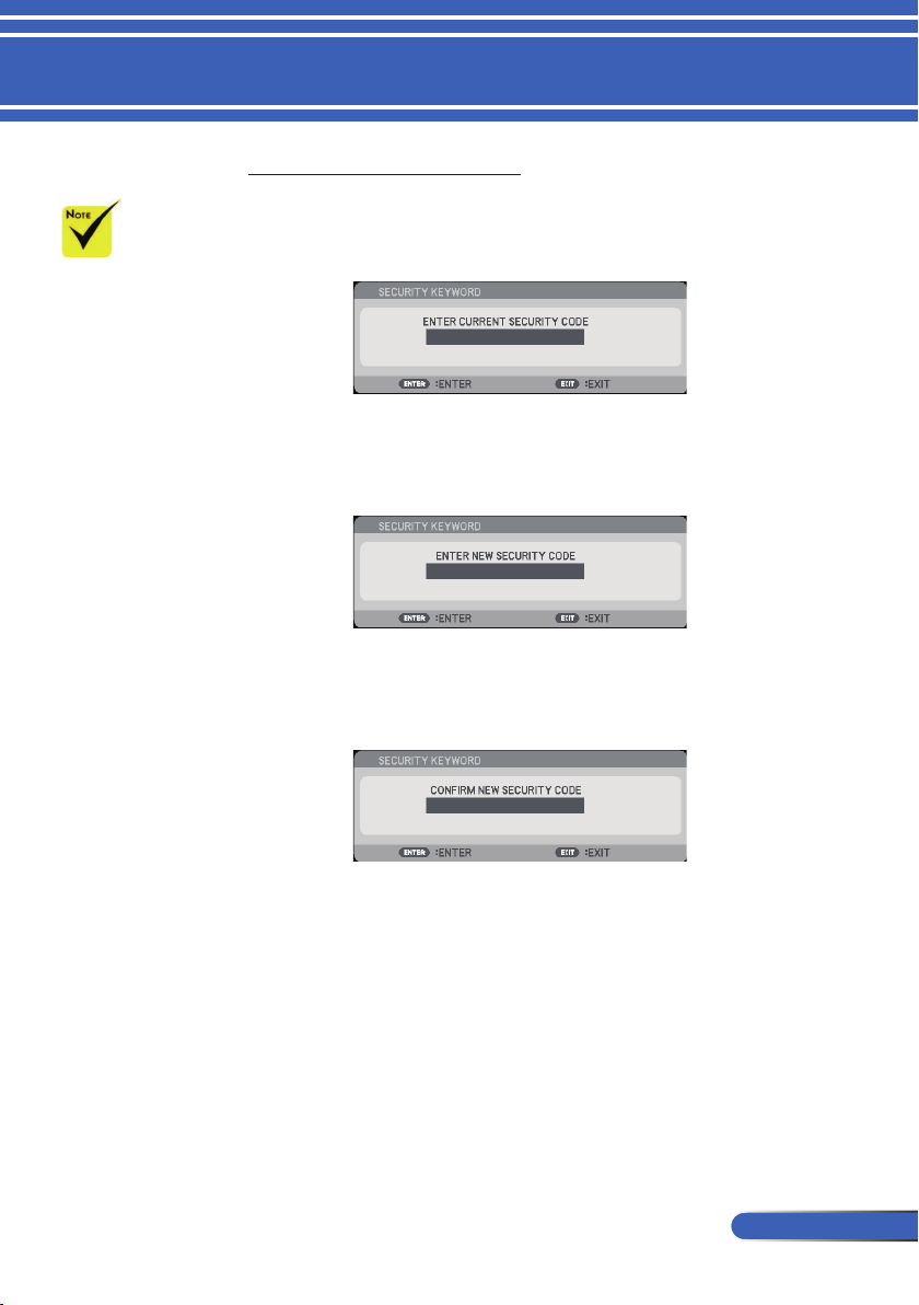
CHANGE PASSWORD
1. Press ENTER to enter SECURITY KEYWORD setting.
2. The password has to be 4 digits.
Current password
3. Use number buttons on the remote control, to enter your
old password and then press ENTER to con rm your
password.
Input new password
4. Use number buttons on the remote control, to enter your
new password and then press ENTER to con rm your
password.
Con rm new password
5. Enter the new password again and press ENTER to
con rm.
If the incorrect password is entered 3 times, the projector will
automatically shut down. (When turn on the projector.)
If you have forgotten your password, please contact your local
of ce for support.
Password default
value is “1234”
( rst time).
48
English ...
User Controls
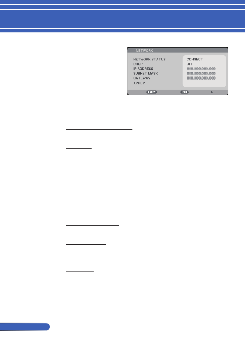
NETWORK STATUS
Display the network connection status. (default: DISCONNECT)
DHCP
Use this function to select your desired startup screen. If you
change the setting from one to another, when you exit the OSD
menu, the new setting will take effect on next open.
ON: Assign an IP address to the projector from an external
DHCP server automatically.
OFF: Assign an IP address manually.
IP ADDRESS
Select an IP address.
SUBNET MASK
Select subnet mask number.
GATEWAY
Select the default gateway of the network connected to the
projector.
APPLY
Press ENTER to apply the selection.
SETTING |
ADVANCED |
NETWORK
49
... English
User Controls
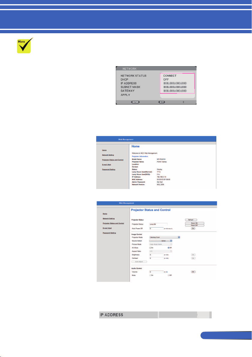
1. Turn on DHCP to allow the DHCP server to automatically assign
an IP, or manually enter the required network information.
2. Then choose apply and press ENTER button to complete the
con guration process.
3. Open your web browser and type in from the OSD LAN screen
then the web page will display as below:
4. Open “Projector Status and Control” to control your projector.
When making a direct connection from your computer to the
projector
Step 1: Find an IP Address (default:192.168.0.10) from LAN
function of projector.
192.168.0.10
How to use web browser to control your projector
When you used the
projector IP address,
you can not link to
your service server.
PJLink: Set a pass-
word for PJLink.
PJLink is a stan-
dardization of
protocol used for
controlling projec-
tors of different
manufacturers. This
standard protocol is
established by Japan
Business Machine
and Information
System Industries
Association (JBMIA)
in 2005.
The projector
supports all the
commands of PJLink
Class 1.
AMX BEACON:
Turn on or off for
detection from AMX
Device Discovery
when connecting to
the network sup-
ported by AMX's
NetLinx control
system.
CRESTRON ROOM-
VIEW compatibility:
The projector sup-
ports CRESTRON
ROOMVIEW, allow-
ing multiple devices
connected in the
network to be man-
aged and controlled
from a computer or a
controller.
For more informa-
tion, visit http://
www.crestron.com
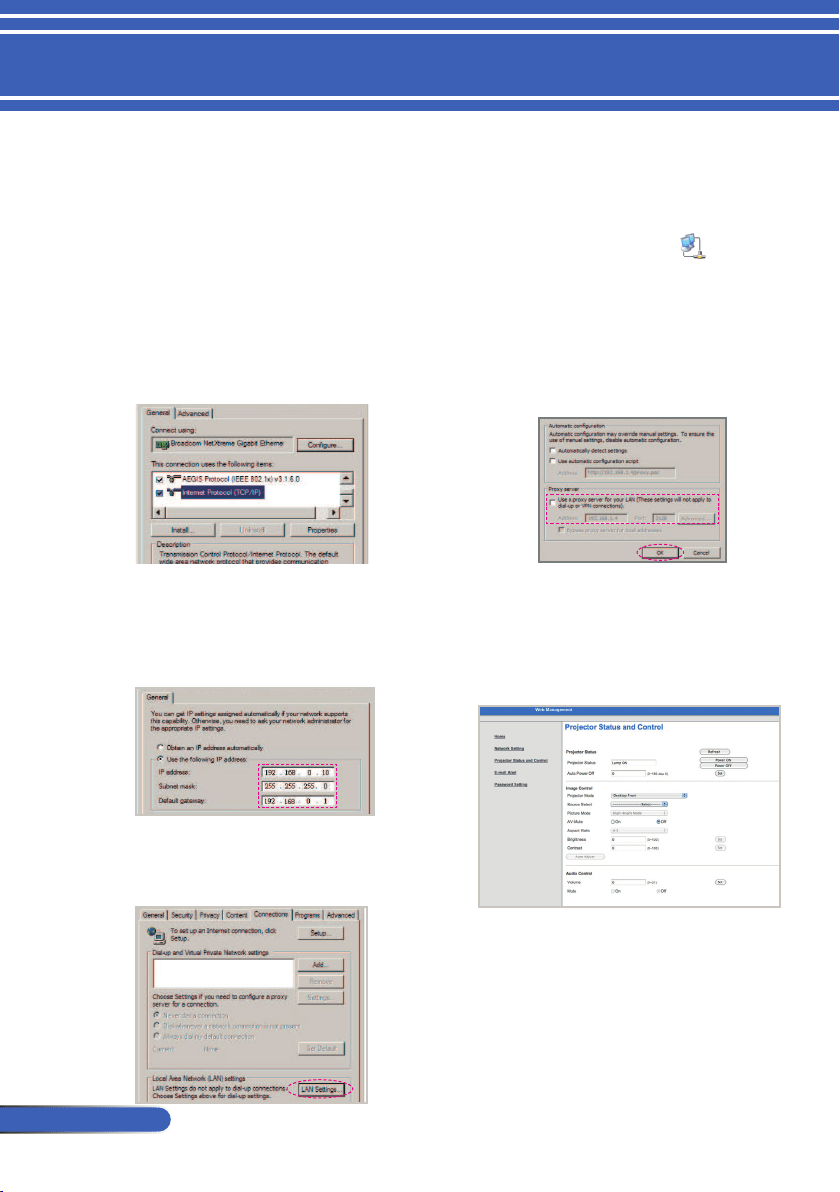
50
English ...
User Controls
Step 2: Select apply and press the ENTER button on the remote control or the control
panel to submit function or press the MENU button on the remote control or
the control panel to exit.
Step 3: To open Network Connections, click
Start
, click
Control Panel
, click
Network
and Internet Connections
, and then click
Network Connections
. Click the
connection you want to congure, and then, under
Network Tasks
, click
Change settings of this connection
.
Step 4: On the
General
tab, under
This
connection uses the following
items
, click
Internet Protocol
(TCP/IP)
, and then click
“Properties.”
Step 5: Click
Use the following IP
address
, and type in as below:
1) IP address: 192.168.0.10
2) Subnet mask: 255.255.255.0
3) Default gateway:192.168.0.1
Step 6: To open Internet Options, click
IE web browser, click Internet
Options, click the
Connections tab
and click “LAN Settings...”
Step 7: The
Local Area Network (LAN)
Setting
dialog box appears
,
In
the
Proxy Server area
, cancel the
Use a proxy server for your LAN
check box
., then click
“OK” button
twice.
Step 8: Open your IE and type in the IP
address of 192.168.0.10 in the URL
then press
the ENTER button key.
Step 9: Open
“Projector Status and
Control” to control your projector.
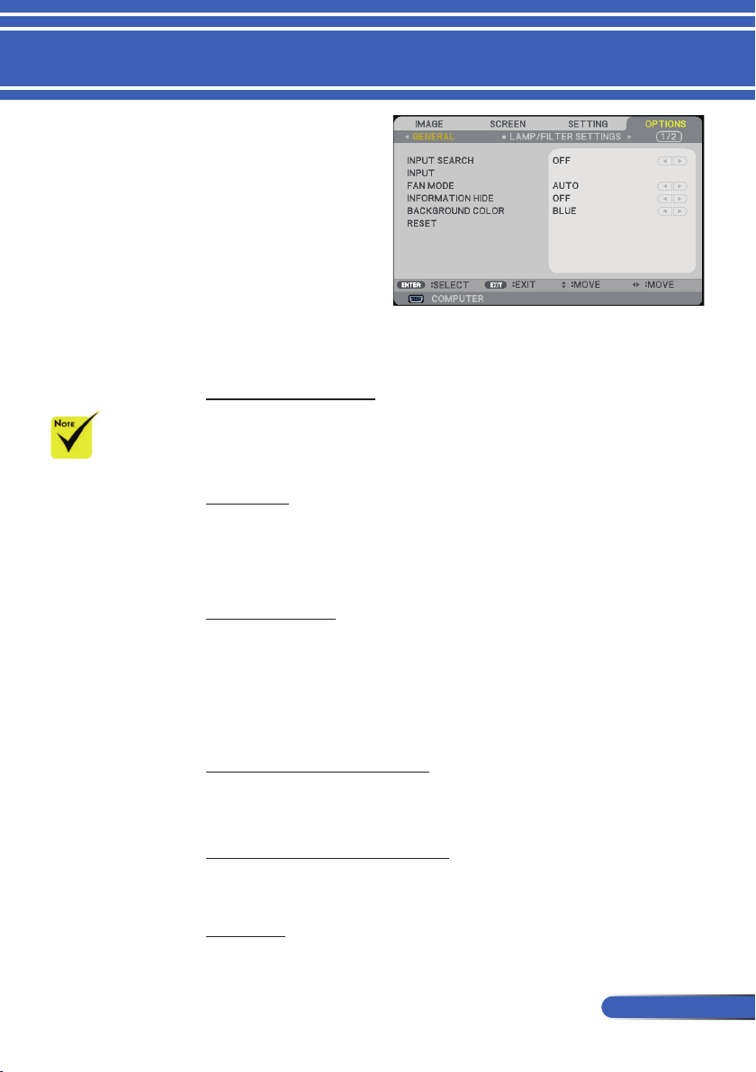
51
... English
User Controls
INPUT SEARCH
ON: The projector will search for other signals if the current
input signal is lost.
OFF: The projector will only search current input connection.
INPUT
Use this option to enable / disable input sources. Press ENTER to
enter the sub menu and select which sources you require. Press
the ENTER button to finalize the selection. The projector will not
search for inputs that are not selected.
FAN MODE
AUTO: The built-in fans automatically run at a variable speed
according to the internal temperature.
HIGH SPEED: The built-in fans run at high speed.
Select this option when using the projector at altitudes
approximately 2500 feet/760 meters or higher.
INFORMATION HIDE
ON: Choose “ON” to hide the info message.
OFF: Choose “OFF” to show the “SEARCHING” message.
BACKGROUND COLOR
Use this feature to display a “BLACK”or “BLUE” screen when no
signal is available.
RESET
Choose “YES” to return the display parameters on all menus to
the factory default settings.
With the optional
dust lter installed,
“HIGH SPEED” is
selected for “FAN
MODE”. Dust lter
is Optional and
may not be required
in some regions.
OPTIONS |
GENERAL
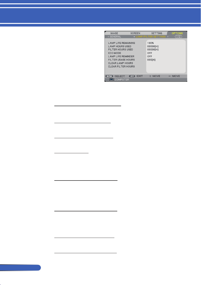
52
English ...
User Controls
LAMP LIFE REMAINING
Showing the Lamp life.
LAMP HOURS USED
Display the projection time.
FILTER HOURS USED
Display the lter used time.
ECO MODE
Choose “ECO” to dim the projector lamp which will lower power
consumption and extend the lamp life. Choose “OFF” to return to
normal mode.
LAMP LIFE REMINDER
Choose this function to show or to hide the warning message
when the changing lamp message is displayed.
The message will appear when the lamp has reached the end of its
life.
FILTER USAGE HOURS
Display the time preference between displaying the message for
cleaning the lter. Clean the lter when you get the message .
When "000[H]" is set, the message will not be displayed.
CLEAR LAMP HOURS
Reset the lamp hour counter after replacing the lamp.
CLEAR FILTER HOURS
Reset the lter hour counter after replacing the lter.
OPTIONS |
LAMP/FILTER
SETTINGS

53
... English
User Controls
INFORMATION
To display the projector information for source, resolution, and
software version on the screen.
OPTIONS |
INFORMATION
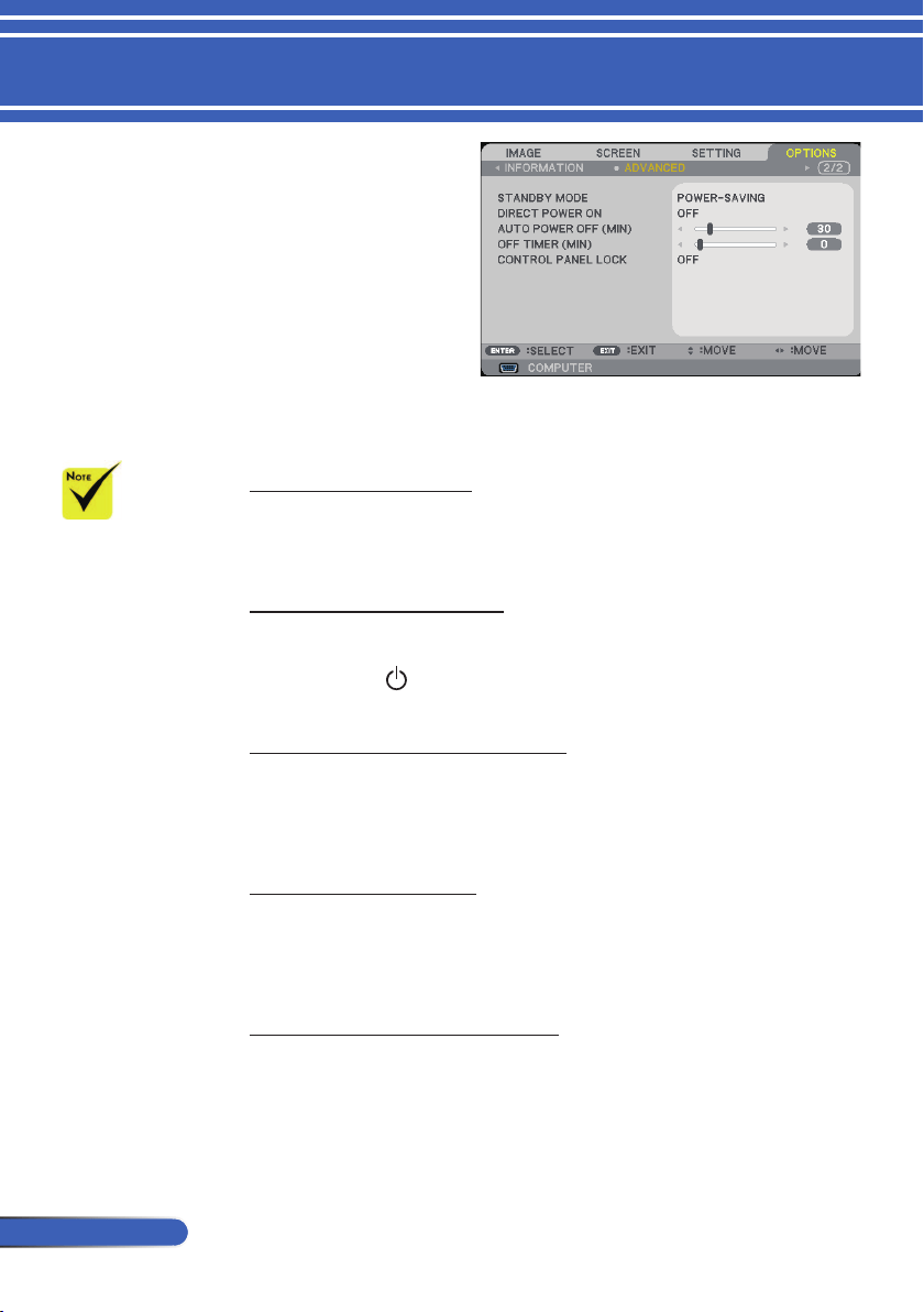
54
English ...
User Controls
STANDBY MODE
POWER-SAVING: Choose “POWER-SAVING” to save power
dissipation further < 0.5W.
NORMAL: Choose “NORMAL” to return to normal standby.
DIRECT POWER ON
Choose “ON” to activate Direct Power mode. The projector will
automatically power on when AC power is supplied, without
pressing the
buton on the projector control panel or the POWER
ON button on the remote control.
AUTO POWER OFF (MIN)
Sets the countdown timer interval. The countdown timer will start,
when there is no signal being sent to the projector. The projector
will automatically power off when the countdown has nished (in
minutes).
OFF TIMER (MIN)
Sets the countdown timer interval. The countdown timer will start,
with or without a signal being sent to the projector. The projector
will automatically power off when the countdown has nished (in
minutes).
CONTROL PANEL LOCK
When the keypad lock function is “ON”, the control panel will
be locked however, the projector can be operated by the remote
control. By selecting “OFF”, you will be able to reuse the control
panel. Press and hold the EXIT button on the projector cabinet for
about 10 seconds to turn off “CONTROL PANEL LOCK”.
Power-Saving mode
will disable the fol-
lowing connectors,
buttons or functions
when the projector is
in standby:
- AUDIO OUT con-
nector
- LAN and Mail
Alert functions
- Buttons other than
POWER button on
the cabinet
- Buttons other than
POWER ON but-
ton on the remote
control
- PC Control con-
nector
- Virtual Remote
Tool, PC Control
Utility Pro 4/PC
Control Utility
Pro 5
OPTIONS |
ADVANCED

55
... English
Appendices
Problem: No image appears on screen
Ensure all the cables and power connections are correctly and
securely connected as described in the “Installation” section.
Ensure the pins of connectors are not crooked or broken.
Check if the projection lamp has been securely installed. Please
refer to the “Replacing the lamp” section.
Make sure the projector is switched on.
Ensure that the “AV-MUTE” feature is not turned on.
Problem: Partial, scrolling or incorrectly displayed image
Press “AUTO ADJ.” on the remote control or control panel.
If you are using a PC:
For Windows 95, 98, 2000, XP, Windows 7:
1. From the “My Computer” icon, open the “Control Panel” folder,
and double click the “Display” icon.
2. Select the “Settings” tab
3. Click on the “Advanced Properties”.
For Windows Vista:
1. From the “My Computer” icon, open the “Control Panel” folder,
and double click the “Appearance and Personalization”
2. Select “Personalization”
3. Click “Adjust screen resolution” to display “Display Settings”.
Click on the “Advanced Settings”.
If the projector is still not projecting the whole image, you will
also need to change the monitor display you are using. Refer to
the following steps.
Troubleshooting
If you experience trouble with the projector, refer to the fol-
lowing information. If the problem persists, please contact
your local dealer or service center.

56
English ...
Appendices
4. Verify the resolution setting is less than or equal to 1280 x 1024
resolution.
5. Select the “Change” under the “Monitor” tab .
6. Click on “Show all devices”. Next, select “Standard monitor
types” under the SP box; choose the resolution mode you need
under the “Models” box.
If you are using a Notebook:
1. First, follow the steps above to adjust resolution of the com
-
puter.
2. Press the toggle output settings. example: [Fn]+[F4]
If you experience difculty changing resolutions or your monitor
freezes, restart all equipment including the projector.
Problem: The screen of the Notebook or PowerBook com-
puter is not displaying a presentation
If you are using a Notebook PC:
Some Notebook PCs may deactivate their own screens when a
second display device is in use. Each has a different way to be
reactivated. Refer to your computer’s documentation for detailed
information.
Problem: Image is unstable or ickering
Adjust the “PHASE” to correct it. Refer to the “SETTING” section
for more information.
Change the monitor color setting from your computer.
Compaq=> [Fn]+[F4]
Dell => [Fn]+[F8]
Gateway=> [Fn]+[F4]
IBM=> [Fn]+[F7]
Macintosh Apple:
System Preference-->Display-->Arrangement-->Mirror
display
Hewlett
=> [Fn]+[F4]
Packard
NEC=> [Fn]+[F3]
Toshiba => [Fn]+[F5]

57
... English
Appendices
Problem: Image has vertical ickering bar
Use “CLOCK” to make an adjustment.
Check and recongure the display mode of your graphic card to
make it compatible with the product.
Problem: Image is out of focus
Adjust the Focus Lever on the projector lens.
Make sure the projection screen is between the required distance
32” to 711”/815 to 18065 mm from the projector (refer to pages 31-
32).
Problem: The image is stretched when displaying 16:9 DVD
The projector automatically detects 16:9 DVD and adjusts the aspect
ratio by digitizing to full screen with 4:3 default setting.
If the image is still stretched, you will also need to adjust the aspect
ratio by referring to the following:
Please select 4:3 aspect ratio type on your DVD player if you are
playing a 16:9 DVD.
If you can’t select 4:3 aspect ratio type on your DVD player,
please select 4:3 aspect ratio in the on screen menu.
Problem: Image is reversed
Select “SETTING|GENERAL-->ORIENTATION” from the OSD
and adjust the projection direction.
Problem: Lamp burns out or makes a popping sound
When the lamp reaches its end of life, it will burn out and may
make a loud popping sound. If this happens, the projector will
not turn on until the lamp module has been replaced. To replace
the lamp, follow the procedures in the “Replacing the Lamp”.
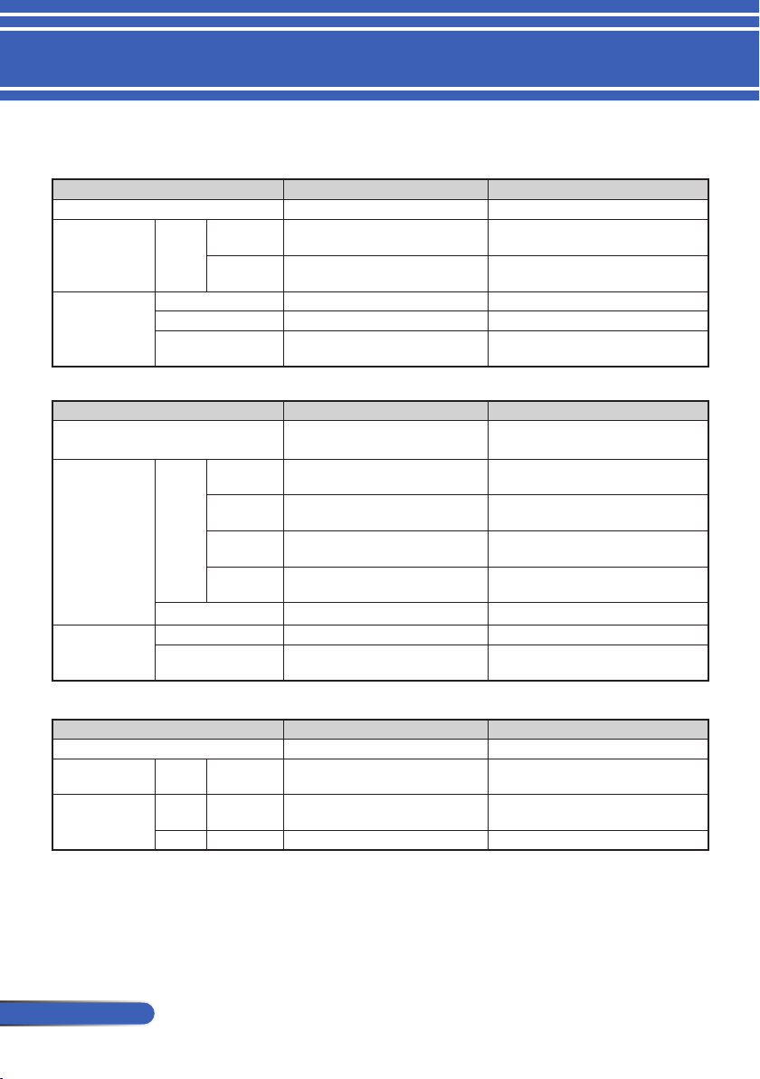
58
English ...
Appendices
Problem: LED lighting message
Power Indicator
Indicator Condition Projector Condition Note
Off The main power is off --
Blinking light Blue 0.5 sec On,
0.5 sec Off
The projector is getting ready to turn on. Wait for a moment.
2.5 sec On,
0.5 sec Off
Off Timer is enabled. --
Steady light Blue The projector is turned on. --
Orange “
Normal” is selected for “Standby Mode” --
Red “
Power-Saving” is selected for “Standby Mode” --
Status Indicator
Indicator Condition Projector Condition Note
Off Normal or Standby (“
Power-Saving” for “Standby
Mode”)
--
Blinking light
Red
2 cycle (0.5 sec
On, 0.5 sec Off)
Temperature error The projector is overheated. Move the projector to a
cooler location.
3 cycle (0.5 sec
On, 0.5 sec Off)
Power error Power unit is not working properly. Contact your dealer.
4 cycle (0.5 sec
On, 0.5 sec Off)
Fan error Fans will not work correctly.
6 cycle (0.5 sec
On, 0.5 sec Off)
Lamp error Lamp fails to light. Wait a full minute and then turn
on again.
Green The projector is cooling down Wait for a moment.
Steady light Green Standby (“
Normal” for “Standby Mode”) --
Orange CONTROL PANEL LOCK is on. You have pressed cabinet button when Control Panel
Lock is on.
Lamp Indicator
Indicator Condition Projector Condition Note
Off Normal --
Blinking light Red Lamp has reached its end of life. Lamp replace-
ment message will be displayed.
Replace the lamp.
Steady light Red Lamp has reached its end of life. The projector will
not turn on until the lamp is replaced.
Wait for a moment.
Green “ECO Mode” is set to “On” --
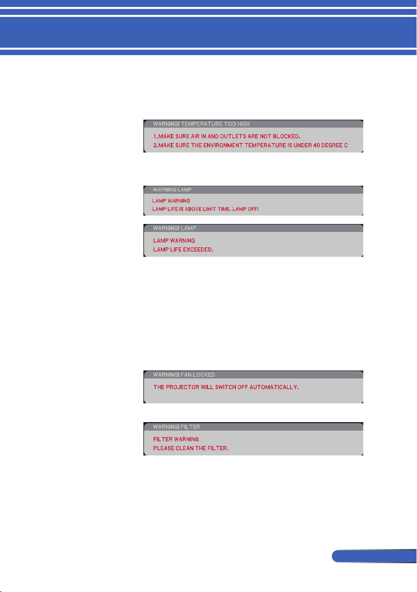
59
... English
Appendices
Problem: Message Reminders
Over temperature - the projector has exceeded its recommended
operating temperature and must be allowed to cool down before it
may be used.
Replacing the lamp - the lamp is about to reach its maximum life-
time. Prepare to replace it soon.
NOTE: When you continue to use the projector for another 100
hours after the lamp has reached the end of its life, the projector
cannot turn on.
If this happens, after replacing the lamp, connect the power cord
and then press and hold the HELP button on the remote control at
least 10 seconds. This will allow you to turn on the projector. Clear
the lamp hours by selecting “OPTIONS” -> “LAMP/FILTER SET-
TINGS” -> “CLEAR LAMP HOURS” from the menu.
Fan failed - the system fan is not working.
Cleaning the lter
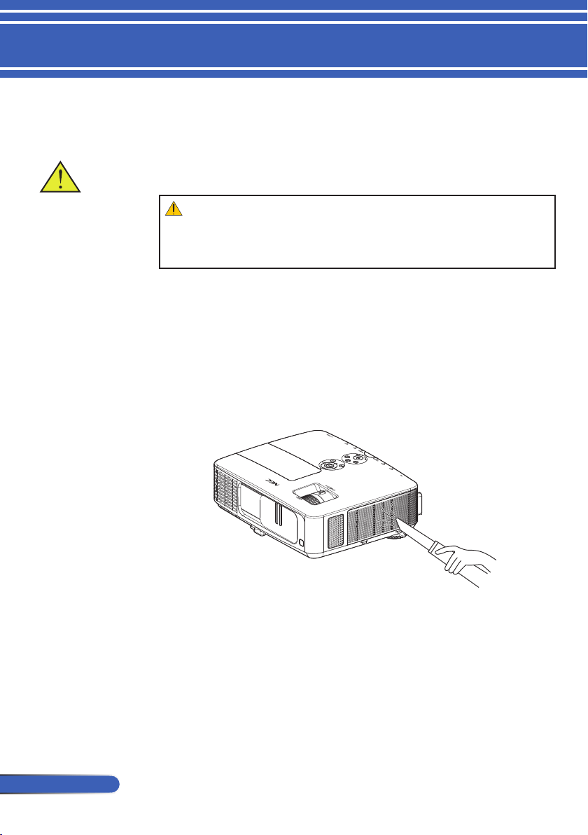
60
English ...
Appendices
Cleaning the Filter
The air-lter sponge keeps dust and dirt from getting inside
the projector and should be frequently cleaned. If the lter is
dirty or clogged, your projector may overheat.
The message for lter
cleaning will be dis-
played for one minute
when the projector is
turned on or off.
To cancel the message,
press any button on
the projector cabinet
or the remote control.
CAUTION:
• Turn off the projector, and unplug the projector before replacing the lter.
• Only clean the outside of the lter cover with a vacuum cleaner.
• Do not attempt to operate the projector without the lter cover.
To clean the air-lter
Use a small vacuum cleaner designed for computers and other
ofce equipment.
If the dirt is difcult to remove or the lter is broken, please
contact your local dealer or service center to obtain a new
lter.
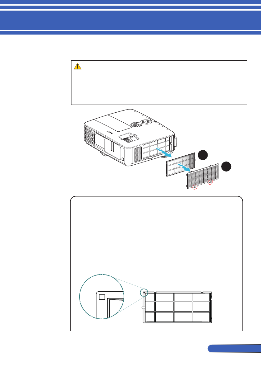
61
... English
Appendices
Replacing Procedure:
1. Turn off the projector and disconnect the power cord.
2. Open the lter cover on the left side of the projector.
u
3. Pull the lter from the lter cover.
v
4. Replace the lter.
Note:
The lter has outside and inside. The lter cover with the lter
in the opposite way cannot be attached to the projector. Attach
the lter to the lter cover with a square mark (□) at the top left
corner as shown in the drawing.
To replace the lter
CAUTION:
• Before replacing the lter, remove dust and dirt from the projector cabinet.
• The projector contains high-precision parts. Keep out dust and dirt during lter
replacement.
• Do not wash the lter with water. Water will damage the lter membrane.
•
Reattach the lter cover correctly. Failure to do so may cause projector malfunction.
1
2

62
English ...
Appendices
5. Install the new lter by reversing the previous steps.
6 After replacing the lter, turn on the power, and press the
[MENU] button -> OPTIONS |LAMP/FILTER SETTINGS ->
CLEAR FILTER HOURS to reset the lter usage hours. Refer to
page 52.
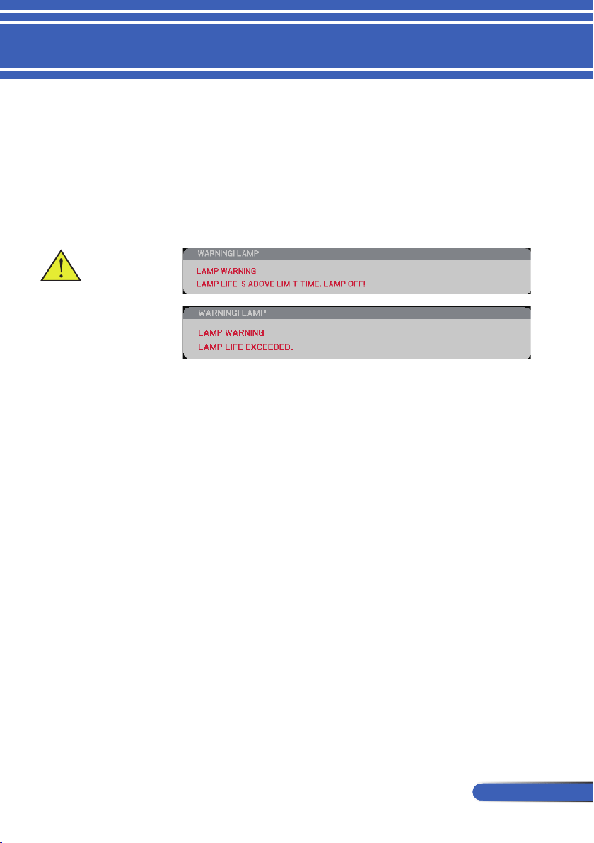
63
... English
Appendices
Replacing the lamp
optional lamp NP24LP
The projector will detect the lamp life at 2500 hours in Eco
Mode Off (3300 hours in Eco Mode On). When the “POWER”
LED indicator ashes red and the message below displays on-
screen, the projector has detected that the lamp is approaching
its end of life. (Refer to page 29) It will show you a warning
message
When you see this message, change the lamp as soon as
possible. Make sure the projector has been cooled down for at
least 60 minutes before changing the lamp.
Warning: To avoid
burns, allow the
projector to cool for
at least 60 minutes
before you replace
the lamp!
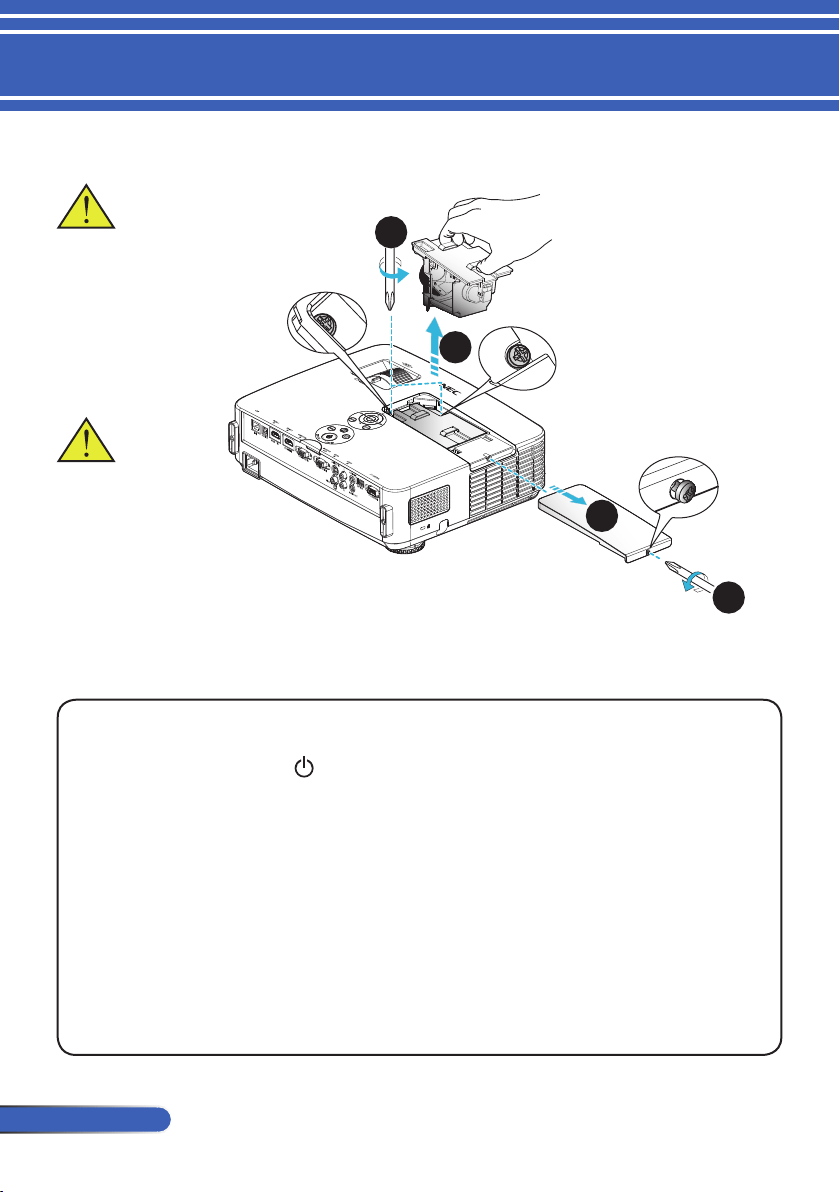
64
English ...
Appendices
1
3
2
Warning: To reduce the
risk of personal injury,
do not drop the lamp
module or touch the
lamp bulb. The bulb
may shatter and cause
injury if it is dropped.
Lamp Replacing Procedure:
1. Switch off the power to the projector by pressing the POWER OFF button on the
remote control or the
button on the control panel.
2. Allow the projector to cool down at least 60 minutes.
3. Disconnect the power cord.
4. Use a screwdriver to loosen the screw on the lamp cover.
5. Slide and remove the cover.
6. Loosen 2 screws on the lamp module and pull up the handle.
7. Pull out the lamp module.
x
8. Install the new lamp module by reversing the previous steps. Be sure to tighten
the screws on the lamp module and the lamp cover.
9. After replacing the lamp, turn on the power, and select the [MENU] button ->
OPTIONS |LAMP/FILTER SETTINGS -> CLEAR LAMP HOURS to reset the
lamp usage hours. Refer to page 52.
Do not break the glass
on the lamp module.
Keep nger prints off
the glass surface on the
lamp module. Leaving
nger prints on the
glass surface might
cause an unwanted
shadow and poor
picture quality.
4
65
... English
Appendices
Cleaning procedure for the lens
If the lens of projection lens is dusty or blemished, please clean
it as following procedure:
1. Turn off the projector and cool projector down for a while.
2. Unplug the power cord from outlet.
3. Blow the dust by blower for cameras which you could buy from
camera shops.Wipe the lens gently using a cleaning cloth.
CAUTION:
• Always wipe the lens with a cleaning cloth.
• Please do not wipe the lens hard because that may cause serious damage
on the surface of lens.
• Wiping might scratch the lens. Optical performance of the projector will
thus be impacted if lens is scratched after wiping. Optical performance
impact will be dependent on the scratch condition of them.
• Do not use liquid cleaners or chemicals on the cloth because it may con-
taminate the cloth and cause serious damage on the surface of lens.
66
English ...
Appendices
Specications
Optical
NP-PE401H
Projection System Single DLP
®
chip (0.65”, aspect ratio 16:9)
Resolution
*1
1920 × 1080 pixels (1080P)
Lens Manual focus/manual zoom
F2.4 (wide): F3.29 (tele)
Lamp 330W AC (248W in ECO mode)
Light Output
*2 *3
4000 lumens
Approx. 75% in ECO mode
Contrast Ratio
*3
(full white:full black)
2000:1 with DYNAMIC CONTRAST ON
Image Size (Diagonal)
23 to 200 inches/0.58 to 5.08 m
Projection Distance
(mini. - max.)
32 to 474 inches/0.82 to 12.0 m
*1 Effective pixels are more than 99.99%.
*2 This is the light output value (lumens) when [Picture Mode] is set to [High-Bright] in the menu. If any other
mode is selected as [Picture Mode], the light output value may drop slightly.
*3 Compliance with ISO21118-200
Electrical
NP-PE401H
Inputs 1 x RGB/Component (D-Sub 15P), 2 x HDMI (19P) HDCP supported
*4
, 1 x S-Video
(DIN 4P), 1 x Video (RCA), 1 x (L/R) RCA Audio, 1 x Stereo Mini Audio
Outputs 1 x RGB (D-Sub 15P), 1 x Stereo Mini Audio
PC Control 1 x PC Control Port (D-Sub 9P)
Wired LAN Port 1 x RJ-45 (10/100 BASE-T)
Service Port 1 x USB (for service purpose only)
Others 1x USB (type A) for future use
Color Reproduction 1.07 billion colors simultaneously, Full color
Compatible Signals
*5
Analog: VGA/SVGA/XGA/XGA+/WXGA/Quad-VGA/WXGA+/SXGA/SXGA+/
WXGA+/WXGA++/UXGA/WSXGA+/HD/Full HD/
480i/480p/576i/576p/720p/1080i/1080p
HDMI: VGA/SVGA/XGA/WXGA/Quad-VGA/SXGA/SXGA+/WXGA+/
WXGA++/WSXGA+/
480i/480p/576i/576p/720p/1080i/1080p
Horizontal Resolution 540 TV lines: NTSC/NTSC4.43/PAL/PAL-M/PAL-N/PAL60
300 TV lines: SECAM
Scan Rate Horizontal: 30 kHz to 100 kHz (RGB: 24 kHz or over)
Vertical: 50 Hz to 120 Hz (HDMI: 50 to 85 Hz)
Sync Compatibility Separate Sync
Built-in Speaker 8W x 2 (monaural)
67
... English
Appendices
Power Requirement 100 - 240V AC, 50/60 Hz
Input Current 100 - 240V, 50-60Hz, 4.3-1.8A
Power Consumption
(Typical value)
ECO Mode On 310W (100-130V)/295W (200-240V)
ECO Mode Off 410W (100-130V)/388W (200-240V)
Standby (Normal) 12W (100-130V/200-240V)
Standby (Power-sav-
ing)
0.5W (100-130V/200-240V)
*4 HDMI
®
(Deep Color, Lip Sync) with HDCP
What is HDCP/HDCP technology?
HDCP is an acronym for High-bandwidth Digital Content Protection. High bandwidth Digital Content Protec-
tion (HDCP) is a system for preventing illegal copying of video data sent over a High-Denition Multimedia
Interface (HDMI).
If you are unable to view material via the HDMI input, this does not necessarily mean the projector is not
functioning properly. With the implementation of HDCP, there may be cases in which certain content is pro-
tected with HDCP and might not be displayed due to the decision/intention of the HDCP community (Digital
Content Protection, LLC).
Video: Deep Color; 8/10/12-bit, LipSync
*5 An image with higher or lower resolution than the projector’s native resolution (1920 × 1080) will be displayed
with scaling technology.
Mechanical
NP-PE401H
Installation Orientation Desktop/Front, Desktop/Rear, Ceiling/Front, Ceiling/Rear
Dimensions 13.8” (W) × 4.1” (H) × 11.1” (D) /350 mm (W) × 105 mm (H) × 281 mm (D)
(not including protrusions)
13.8” (W) × 4.6” (H) × 14.8” (D) /350 mm (W) × 117 mm (H) × 376 mm (D)
(with cable cover and tilt foot)
Weight 9.9 lbs/4.5 kg
Environmental Consid-
erations
Operational Temperatures : 41° to 104°F (5° to 40°C),
(ECO mode selected automatically at 95°F to 104°F/35°C to 40°C)
20% to 80% humidity (non-condensing)
Storage Temperatures : 14° to 122°F (-10° to 50°C),
20% to 80% humidity (non-condensing)
Operating altitude: 0 to 10000 ft/3000 m (HIG SPEED: 2500 feet/760 m to 10000
ft/3000 m)
Regulations UL/C-UL Approved (UL 60950-1, CSA 60950-1)
Meets DOC Canada Class B requirements
Meets FCC Class B requirements
Meets AS/NZS CISPR.22 Class B
Meets EMC Directive (EN55022, EN55024, EN61000-3-2, EN61000-3-3)
Meets Low Voltage Directive (EN60950-1, TÜV GS Approved)
Electrical
NP-PE401H
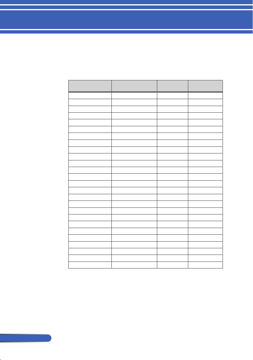
68
English ...
Appendices
Compatibility Modes
Modes Resolution (dots)
V.Frequency
[Hz]
H.Frequency
[KHz]
VGA
640x480
60 31.5
VGA
640x480
72 37.9
VGA
640x480
75 37.5
VGA
640x480
85 43.3
SVGA
800x600
56 35.1
SVGA
800x600
60 37.9
SVGA
800x600
72 48.1
SVGA
800x600
75 46.9
SVGA
800x600
85 53.7
XGA
1024x768
60 48.4
XGA
1024x768
70 56.5
XGA
1024x768
75 60.0
XGA
1024x768
85 68.7
XGA+
1152x864
70 63.9
XGA+
1152x864
75 67.5
XGA+
1152x864
85 77.1
QuadVGA
1280x960
60 60.0
SXGA
1280x1024
60 64.0
SXGA
1280x1024
75 80.0
SXGA
1280x1024
85 91.1
SXGA+
1400x1050
60 65.3
UXGA 1600x1200
60 75.0
IBM 640x480
60 30.3
Apple, Mac II 640x480
67 35.0
Apple, Mac II 832x864
75 49.1
Apple, Mac II 1152x870
75 68.7
(1) VGA Analog - PC Signal
VGA Analog
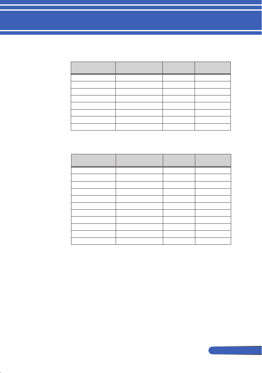
69
... English
Appendices
(2) VGA Analog - Extended Wide timing
Modes Resolution (dots)
V.Frequency
[Hz]
H.Frequency
[KHz]
HD 1280x720 60 44.8
WXGA 1280x768 60 47.8
WXGA 1360x768 60 47.7
WXGA 1366x768 60 47.7
WXGA+ 1440x900 60 55.9
WXGA++ 1600x900 60 59.9
WSXGA+ 1680x1050 60 65.3
Full HD 1920x1080(1080P) 60 67.5
(3) VGA Analog -Component Signal
Modes Resolution (dots)
V.Frequency
[Hz]
H.Frequency
[KHz]
480i 720x480(1440x480) 59.94(29.97) 15.7
576i 720x576(1440x576) 50(25) 15.6
480p 720x480 59.94 31.5
576p 720x576 50 31.3
720p 1280x720 60 45.0
720p 1280x720 50 37.5
1080i 1920x1080 60(30) 33.8
1080i 1920x1080 50(25) 28.1
1080p 1920x1080 23.97/24 27.0
1080p 1920x1080 60 67.5
1080p 1920x1080 50 56.3
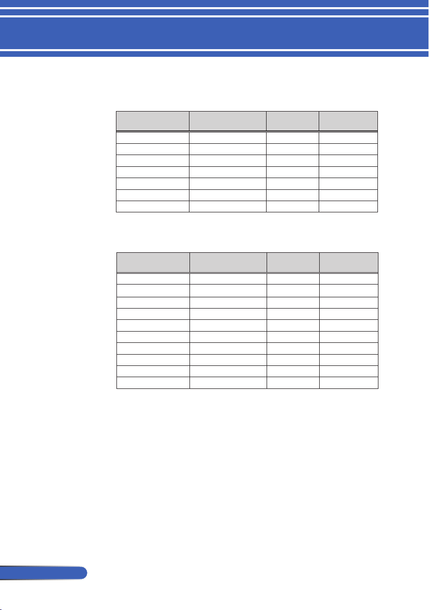
70
English ...
Appendices
Modes Resolution (dots)
V.Frequency
[Hz]
H.Frequency
[KHz]
VGA
640x480
60
31.5
SVGA
800x600
60
37.9
XGA
1024x768
60
48.4
QuadVGA
1280x960
60
60.0
SXGA
1280x1024
60
64.0
SXGA
1280x1024
75
80.0
SXGA+
1400x1050
60
65.3
(1) HDMI - PC Signal
HDMI Digital
(2) HDMI - Extended Wide timing
Modes Resolution (dots)
V.Frequency
[Hz]
H.Frequency
[KHz]
HD 1280x720 60 44.8
HD 1280x720 120 92.9
WXGA 1280x768 60 47.8
WXGA 1280x800 60 49.6
WXGA 1360x768 60 47.7
WXGA 1366x768 60 47.7
WXGA+ 1440x900 60 59.9
WXGA++ 1600x900 60 59.9
WSXGA+ 1680x1050 60 65.3
Full HD 1920x1080(1080P) 60 67.5
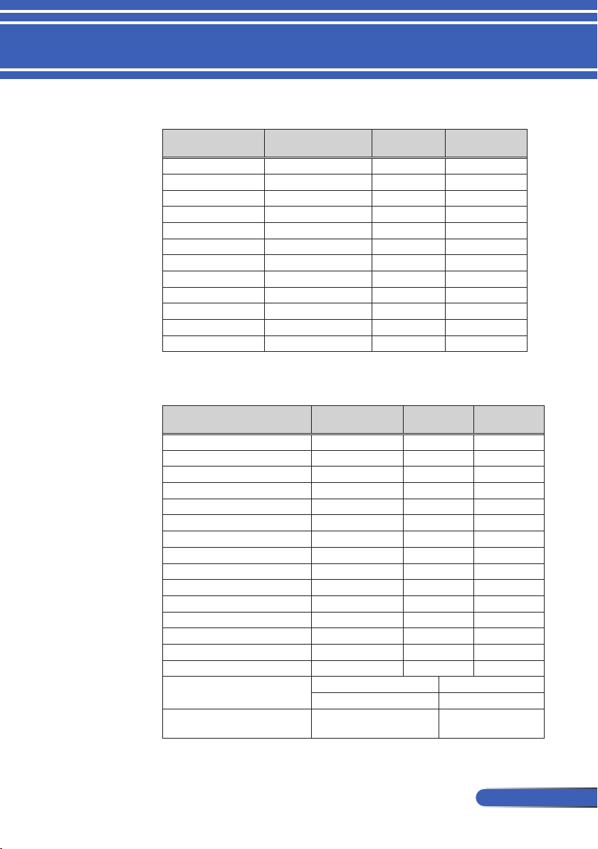
71
... English
Appendices
(3) HDMI - Video Signal
Modes Resolution (dots)
V.Frequency
[Hz]
H.Frequency
[KHz]
480i 720x480(1440x480) 59.94(29.97) 15.7
576i 720x576(1440x576) 50(25) 15.6
480p 640x480 59.94 31.5
480p 720x480 59.94 31.5
576p 720x576 50 31.3
720p 1280x720 60 45.0
720p 1280x720 50 37.5
1080i 1920x1080 60(30) 33.8
1080i 1920x1080 50(25) 28.1
1080p 1920x1080 23.97/24 27.0
1080p 1920x1080 60 67.5
1080p 1920x1080 50 56.3
(4) HDMI – 1.4a 3D Timing
Modes Resolution (dots)
V.Frequency
[Hz]
H.Frequency
[KHz]
720p (Frame Packing) 1280x720 50 37.5
720p (Frame Packing) 1280x720 60
45.0
1080p (Frame Packing ) 1920x1080 24 27.0
720p (Top and Bottom ) 1280x720 50 37.5
720p (Top and Bottom ) 1280x720 60 45.0
1080i (Top and Bottom) 1920x1080 50(25) 28.1
1080i (Top and Bottom) 1920x1080 60(30) 33.8
1080p (Top and Bottom) 1920x1080 24 27.0
1080p (Top and Bottom) 1920x1080 50 56.3
1080p (Top and Bottom) 1920x1080 60 67.5
720p (Side by Side (Half)) 1280x720 60 45.0
1080i (Side by Side (Half)) 1920x1080
50(25)
28.1
1080i (Side by Side (Half)) 1920x1080
60(30)
33.8
1080p (Side by Side (Half)) 1920x1080
50
56.3
1080p (Side by Side (Half)) 1920x1080
60
67.5
Graphic source monitor range limits
Horizontal scan rate:
30k-100kHz
Vertical scan rate:
50-120Hz
Max. pixel rate
Analog:162MHz
Digital:165MHz

72
English ...
Appendices
TIP:
• An image with higher or lower resolution than the projector’s native
resolution (1920 × 1080 ) will be displayed with scaling technology.
• Sync on Green and Composite sync signals are not supported.
• Signals other than those specied in the table above may not be displayed
correctly. If this should happen, change the refresh rate or resolution on
your PC. Refer to Display Properties help section of your PC for proce-
dures.
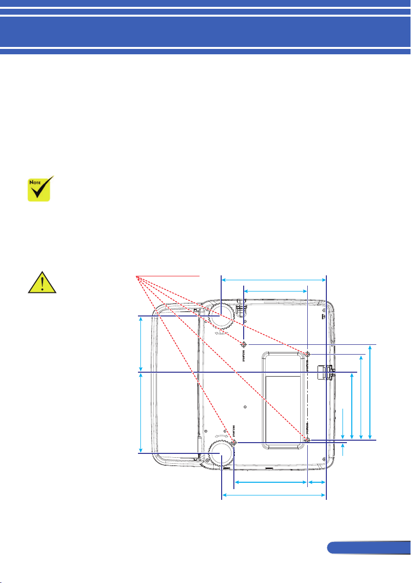
73
... English
Appendices
Please note that dam-
age resulting from
incorrect installation
will invalidate the war-
ranty.
Ceiling Mount Installation
1. To prevent damaging your projector, please use the ceil-
ing mount package for installation.
2. If you buy a ceiling mount from another company, please
ensure the screws used to attached a mount to the projec-
tor met the following specications:
Screw type: M4
Maximum screw length: 8mm
Minimum screw length: 6mm
Warning:
1. If you buy a ceiling
mount from another
company, please
ensure that there is at
least 10cm distance
between the bottom
cover of the projector
and the ceiling.
2. Avoid placing
the projector near
sources of heat such
air-conditioning
units and heaters
otherwise it may
overheat and shut
down automatically.
3. Ceiling mounts
should be attached
to metal, concrete or
wood.
213.5 (8.4)
130.0 (5.1)
150.0 (5.9)
213.5 (8.4)
38.5
(1.5)
195.0 (7.7)
175.0 (6.9)
138.0 (5.4)
5.0 (0.2)
115.0 (4.5) 165.0 (6.5)
4-M4*L8 (Max)
for Ceiling Mount
Unit: mm (inch)
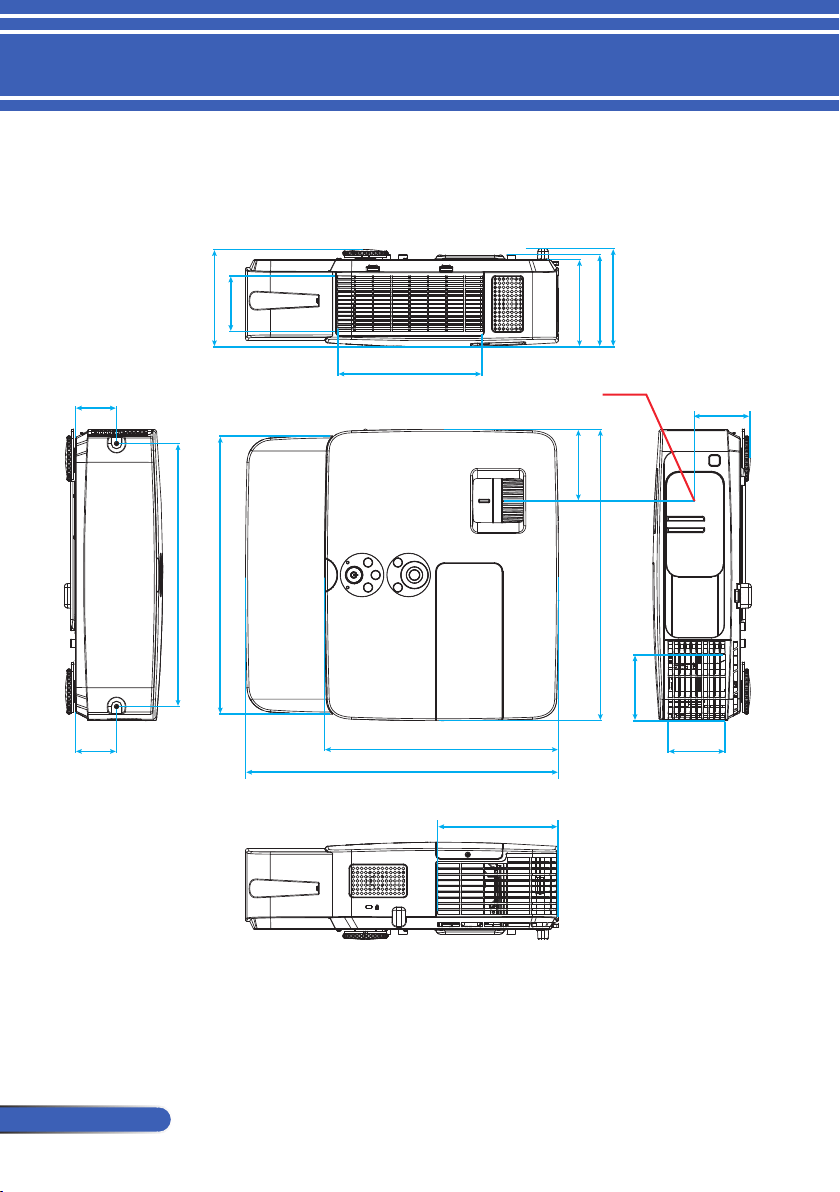
74
English ...
Appendices
Cabinet Dimensions
116.9 (4.6)
66.9 (2.6)
118.2 (4.7)
110.8 (4.4)
105.0 (4.1)
86.0 (3.4)
350.0 (13.8)
79.2 (3.1)
333.9 (13.1)
316.0 (12.4)
49.5 (1.9)
49.5 (1.9)
281.3 (11.1)
376.0 (14.8)
68.5 (2.7)
144.55 (5.7)
173.1 (6.8)
67.0 (2.6)
Unit: mm (inch)
Lens center
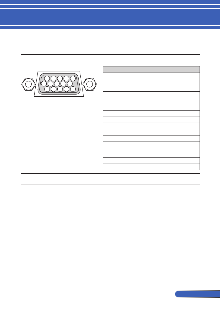
75
... English
Appendices
Pin Assignments of D-Sub COMPUTER Input
Connector
Mini D-Sub 15 Pin Connector
1 2 3 4 5
11 12 13 14 15
6 7 8 9 10
Signal Level
Video signal : 0.7Vp-p (Analog)
Sync signal : TTL level
COMPUTER IN
NOTE: Pin Nos. 12 and 15 are required for DDC/CI.
Pin No. RGB Signal (Analog) YCbCr Signal
1 Red Cr
2 Green Y
3 Blue Cb
4 Ground
5 Ground
6 Red Ground
Cr Ground
7 Green Gro Y Ground
8 Blue Ground Cb Ground
9 No Connection
10 Sync Signal Ground
11 No Connection
12 Bi-directional DATA (SDA)
13
Horizontal Sync or Composite
Sync
14 Vertical Sync
15 Data Clock
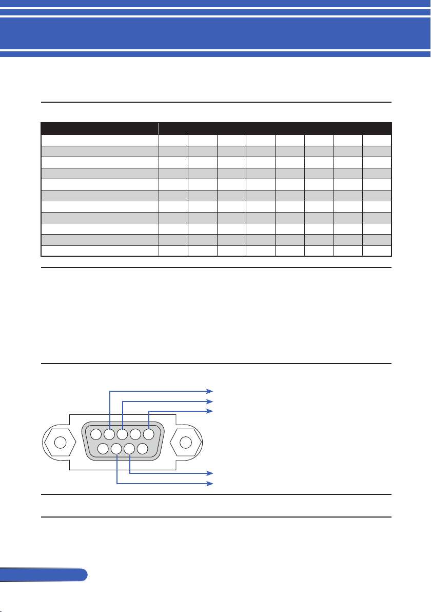
76
English ...
Appendices
PC Control Codes and Cable Connection
PC Control Codes
Function Code Data
POWER ON 02H 00H 00H 00H 00H 02H
POWER OFF 02H 01H 00H 00H 00H 03H
INPUT SELECT COMPUTER 02H 03H 00H 00H 02H 01H 01H 09H
INPUT SELECT HDMI 1 02H 03H 00H 00H 02H 01H 1AH 22H
INPUT SELECT HDMI 2 02H 03H 00H 00H 02H 01H 1BH 23H
INPUT SELECT VIDEO 02H 03H 00H 00H 02H 01H 06H 0EH
INPUT SELECT S-VIDEO 02H 03H 00H 00H 02H 01H 0BH 13H
PICTURE MUTE ON 02H 10H 00H 00H 00H 12H
PICTURE MUTE OFF 02H 11H 00H 00H 00H 13H
SOUND MUTE ON 02H 12H 00H 00H 00H 14H
SOUND MUTE OFF 02H 13H 00H 00H 00H 15H
NOTE: Contact your local dealer for a full list of the PC Control Codes if needed.
Cable Connection
Communication Protocol
Baud rate ....................................................38400 bps
Data length .................................................8 bits
Parity ...........................................................No parity
Stop bit ........................................................One bit
X on/off ........................................................None
Communications procedure ....................Full duplex
PC Control Connector (D-SUB 9P)
3 4 521
9876
NOTE 1: Pins 1, 4, 6 and 9 are no used.
NOTE 2: Jumper “Request to Send” and “Clear to Send” together on both ends of the cable to simplify cable connection.
To TxD of PC
To RxD of PC
To GND of PC
To RTS of PC
To CTS of PC
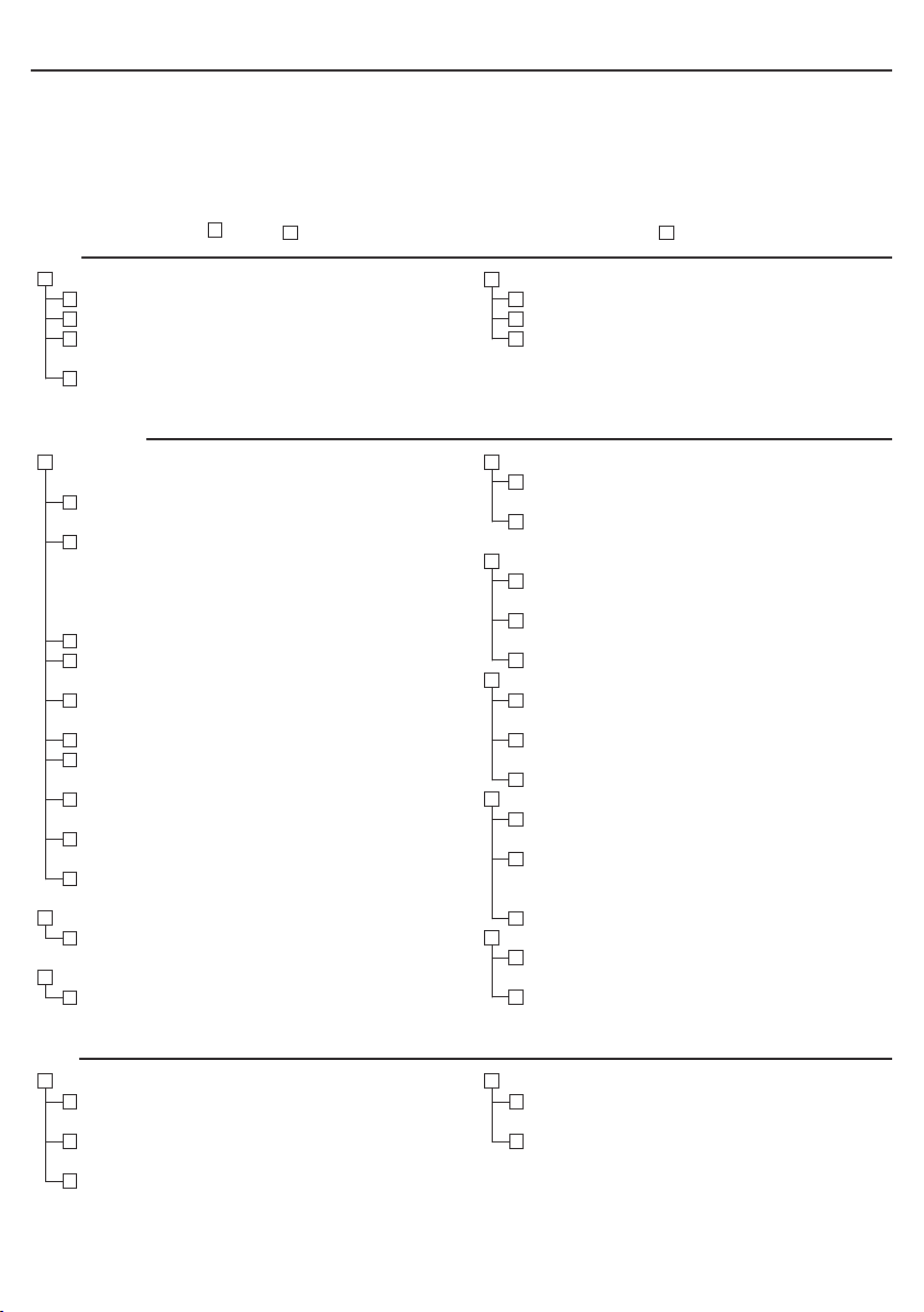
Power
No power (POWER indicator does not light blue).
Power cable’s plug is fully inserted into the wall outlet.
Lamp cover is installed correctly.
Lamp Hours Used (lamp operation hours) was cleared after
lamp replacement.
No power even though you press and hold the POWER
button for a minimum of 1 second.
Shut down during operation.
Power cable’s plug is fully inserted into the wall outlet.
Lamp cover is installed correctly .
Power Management is turned off (only models with the
Power Management function).
Video and Audio
No image is displayed from your PC or video equipment to the
projector.
Still no image even though you connect the projector to the
PC rst, then start the PC.
Enabling your notebook PC’s signal output to the projector.
• A combination of function keys will enable/disable the
external display. Usually, the combination of the “Fn” key
along with one of the 12 function keys turns the external
display on or off.
No image (blue background).
Still no image even though you press the AUTO ADJUST
button.
Still no image even though you carry out [RESET] in the
projector’s menu.
Signal cable’s plug is fully inserted into the input connector
A message appears on the screen.
( _____________________________________________ )
The source connected to the projector is active and avail-
able.
Still no image even though you adjust the brightness and/or
the contrast.
Input source’s resolution and frequency are supported by
the projector.
Image is too dark.
Remains unchanged even though you adjust the brightness
and/or the contrast.
Image is distorted.
Image appears to be trapezoidal (unchanged even though
you carry out the [KEYSTONE] adjustment).
Parts of the image are lost.
Still unchanged even though you press the AUTO ADJUST
button.
Still unchanged even though you carry out [RESET] in the
projector’s menu.
Image is shifted in the vertical or horizontal direction.
Horizontal and vertical positions are correctly adjusted on a
computer signal.
Input source’s resolution and frequency are supported by
the projector.
Some pixels are lost.
Image is ickering.
Still unchanged even though you press the AUTO ADJUST
button.
Still unchanged even though you carry out [RESET] in the
projector’s menu.
Image shows ickering or color drift on a computer signal.
Image appears blurry or out of focus.
Still unchanged even though you checked the signal’s reso-
lution on PC and changed it to projector’s native resolution.
The throw distance is within 39.4” to 433.1” (1,000 to 11,000
mm).
Still unchanged even though you adjusted the focus.
No sound.
Audio cable is correctly connected to the audio input of the
projector.
Still unchanged even though you adjusted the volume level.
Other
Remote control does not work.
No obstacles between the sensor of the projector and the
remote control.
Projector is placed near a uorescent light that can disturb
the infrared remote controls.
Batteries are new and are not reversed in installation
Buttons on the projector cabinet do not work.
[CONTROL PANEL LOCK] is not turned on in the menu.
Still unchanged even though you press and hold the EXIT
button for minimum of 10 seconds.
Troubleshooting Check List
Before contacting your dealer or service personnel, check the following list to be sure repairs are needed also by
referring to the “Troubleshooting” section in your user’s manual. This checklist below will help us solve your
problem more efciently.
* Print the following pages.
Frequency of occurrence
always sometimes (How often?_______________________) other (__________________)
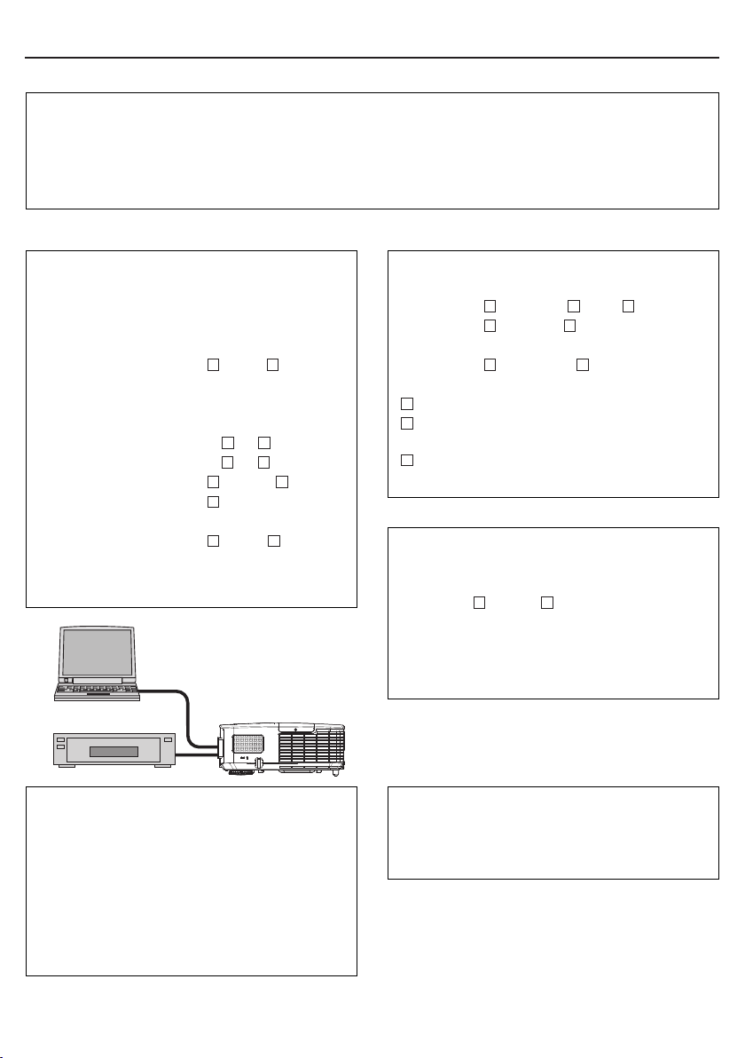
In the space below please describe your problem in detail.
Information on application and environment where your projector is used
Projector
Model number:
Serial No.:
Date of purchase:
Lamp operating time (hours):
Lamp Mode:
Normal Eco
Information on input signal:
Horizontal synch frequency [ ] kHz
Vertical synch frequency [ ] Hz
Synch polarity H
(+) (–)
V
(+) (–)
Synch type
Separate Composite
Sync on Green
STATUS Indicator:
Steady light
Orange Blue
Flashing light [ ] cycles
Remote control model number:
Installation environment
Screen size: inch
Screen type:
White matte Beads Polarization
Wide angle High contrast
Throw distance: feet/inch/m
Orientation:
Ceiling mount Desktop
Power outlet connection:
Connected directly to wall outlet
Connected to power cord extender or other (the number
of connected equipment______________)
Connected to a power cord reel or other (the number of
connected equipment______________)
Computer
Manufacturer:
Model number:
Notebook PC
/ Desktop
Native resolution:
Refresh rate:
Video adapter:
Other:
Video equipment
VCR, DVD player, Video camera, Video game or other
Manufacturer:
Model number:
Signal cable
NEC standard or other manufacturer’s cable?
Model number: Length: inch/m
Distribution amplier
Model number:
Switcher
Model number:
Adapter
Model number:
Projector
PC
DVD Player

REGISTER YOUR PROJECTOR!
(for residents in the United States, Canada, and Mexico)
Please take time to register your new projector. This will activate your lim-
ited parts and labor warranty and InstaCare service program.
Visit our web site at
www.necdisplay.com, click on support center/register
product and submit your completed form online.
Upon receipt, we will send a conrmation letter with all the details you will
need to take advantage of fast, reliable warranty and service programs from
the industry leader, NEC Display Solutions of America, Inc.

© NEC Display Solutions, Ltd. 2013 7N951911