Loading ...
Loading ...
Loading ...
English
8
ASSEMBLY AND ADJUSTMENTS
WARNING: To reduce the risk of serious personal
injury, turn unit off and remove the battery pack
before making any adjustments or removing/
installing attachments or accessories. An
accidental start-up can causeinjury.
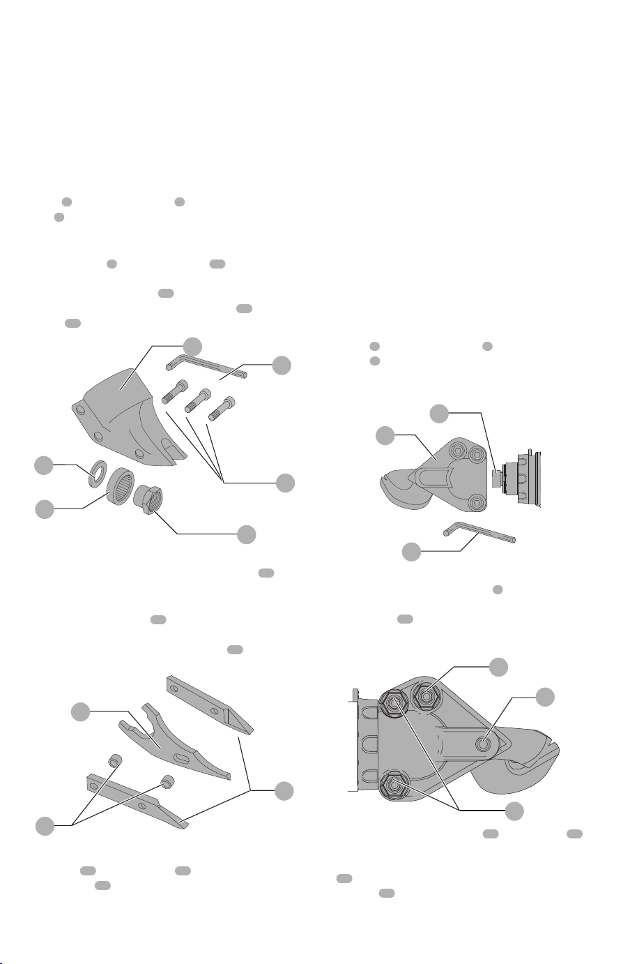
Remove and Replace Parts (Fig. A, D, E)
DCs491, DCs494
To remove shear head from motor, loosen three cap
screws
9
using the hex wrench
4
provided. Remove shear
head
2
by pulling head firmly forward. Slight twisting
action may be required if head does not slide off easily.
To remove cutter blades from shear head, remove
three cap screws
7
from shear housing
10
. Be careful not
to lose rear spacer bushing when removing middle cap
screw. Remove center blade
11
from housing by tapping
blade gently towards the rear. The side knives
12
and side
spacers
13
will now drop out of the housing.
Fig. D
9
4
16
15
10
14
To remove eccentric bearing assembly from shaft,
use an appropriate wrench to loosen eccentric nut
14
by
turning counterclockwise.
To install eccentric bearing assembly onto shaft, make
sure the large, thin washer
15
is first inserted over shaft.
Screw eccentric bearing assembly onto shaft and tighten
with appropriate wrench. Lubricate bearing
16
with a good
grade of bearing grease.
Fig. E
13
11
12
To install cutter blades into shear housing, place the
side knives
12
and side spacers
13
into position in the
shear housing
10
. Insert center cap screw through side
knife and side spacer with rear spacer bushing between
them. Start cap screw into thread just enough to hold
blades in place. DO NOT TIGHTEN. Insert spacer bushing
into hole in center blade and lubricate. Install center blade
into shear housing by tapping blade gently forward using a
drift pin to line up hole in center blade with forward holes in
housing. Insert and tighten forward cap screw making sure
spacer bushing in center blade stays in position. Apply good
grade of bearing grease to clevis or yoke in center blade
where it rides on the eccentric bearing assembly. Insert
rear cap screw into shear housing but do not completely
tighten.
To install shear head assembly onto drive motor, make
sure all cap screws are loosened about 3 or 4 complete
turns. Place shear head onto unit and alternately tighten
cap screws snugly to lock head assembly in place. It may be
necessary to gently tap the shear head into place if it does
not readily slip onto the nose of the power unit.
Remove and Replace Parts (Fig. A, F–H)
DCs496
To remove shear head from motor, loosen the two back
cap screws
9
using the hex wrench
4
provided. Remove
shear head
2
from the body by pulling head firmly forward
(Fig.F). Slight twisting action may be required if head does
not slide off easily.
2
4
13
Fig. F
To remove cutter blades from the shear head,
completely loosen the two cap screws
9
closest to the
collar and remove shear head from motor unit. Loosen the
tensioning screw
17
1/2 turn. Completely loosen all three
cap screws and remove head assembly. Turn assembly over
and remove top half of head and then remove the blades.
9
9
17
Fig. G
To replace blades, place lower jaw
18
onto two pins
20
.
Apply a thin layer of grease from the packet (included)
around the pin and on the top side of the blade. Place upper
jaw
19
onto pin. Apply the rest of the grease provided onto
the eccentric
13
on the output shaft of the motor unit and
into the area behind the upper moving blade in the shear
head.
Loading ...
Loading ...
Loading ...