Loading ...
Loading ...
Loading ...
Installation
Instructions
See
Figures
5
thru
8
and
Wiring
Diagram
on
unit.
Use
of
Rigid
Metal
Conduit
It
is
recommended
that
wires
be
tied
together
or
twisted
to-
gether
inside
the
conduit.
This
will
minimize
any
buzzing
type
sounds
that
could
be
produced
with
high
current
loads,
such
as
during
starting.
Under
some
conditions
it
may
be
necessary
to
use
a
hard
start
kit
to
eliminate
prob-
lem
noises.
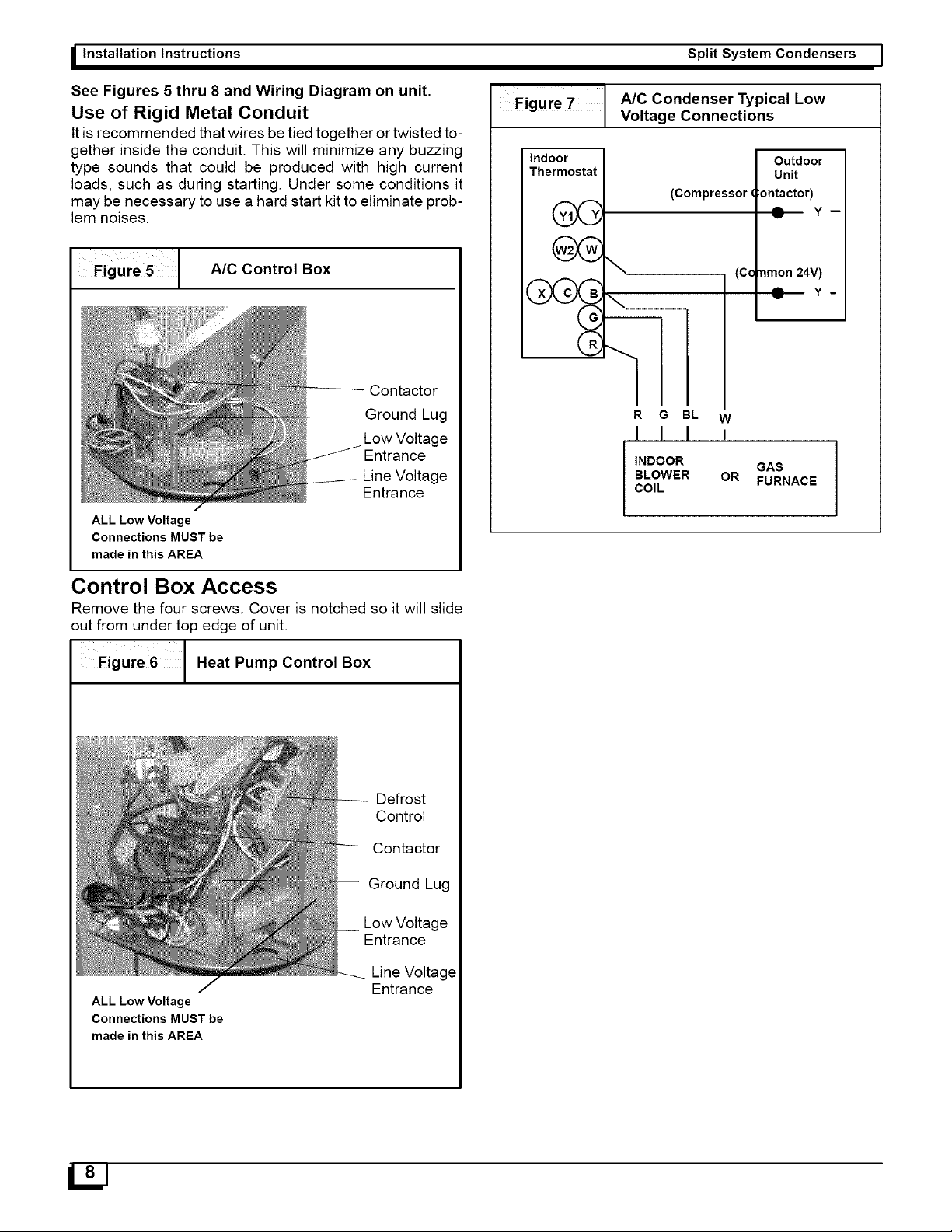
Figure
5
A/C
Control
Box
Contactor
Ground
Lug
Low
Voltage
Entrance
Line
Voltage
Entrance
ALL Low
Voltage
Connections
MUST
be
made
in
this
AREA
Control
Box
Access
Remove
the
four
screws.
Cover
is
notched
so
it
will
slide
out
from
under
top
edge
of
unit.
Figure
6
Heat
Pump
Control
Box
Defrost
Control
Contactor
Ground
Lug
Low
Voltage
Entrance
Line
Voltage
Entrance
ALL Low
Voltage
Connections
MUST
be
made
in
this
AREA
Split
System
Condensers
Figure
7
AIC
Condenser
Typical
Low
Voltage
Connections
Indoor
Outdoor
Thermostat
Unit
(Compressor
Gontactor)
vik
Y,
@—
Y-
»*
(Common
24V)
XA
CAB
@—
Y-
R
R
G
BL
w
{|
J J
INDOOR
GAS
BLOWER
OR
COIL
FURNACE
Loading ...
Loading ...
Loading ...