Loading ...
Loading ...
Loading ...
10
E
7.
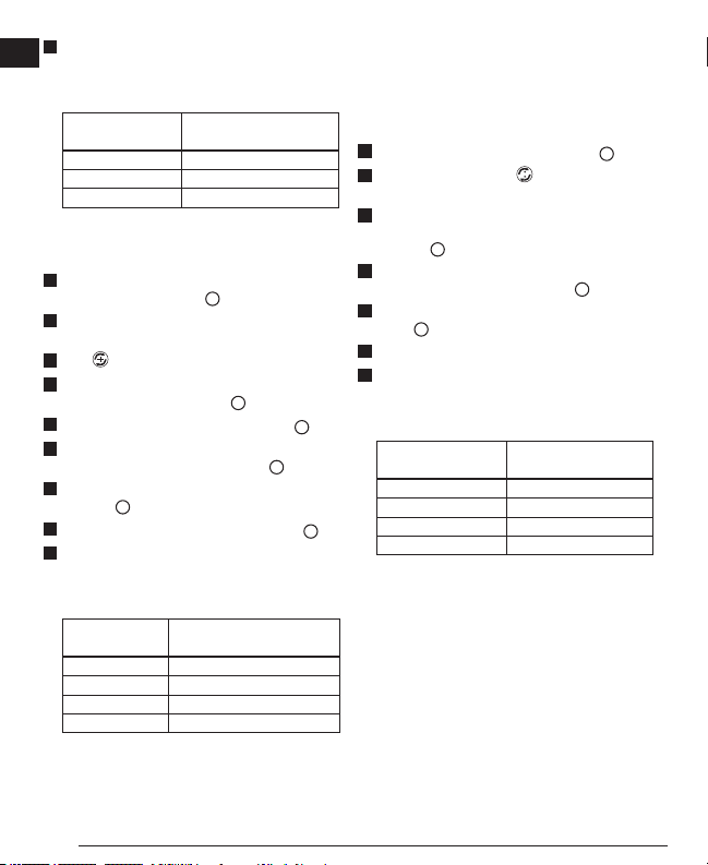
If your measurement is greater than the Allowable
Distance Between P1 & P3 for the corresponding
Distance Between P1 & P2 in the following table, the laser
must be serviced at an authorized service center.
Distance Between
P1 & P2
Allowable Distance
Between P1 and P3
30’ (9m) 7/32” (5.5mm)
40’ (12m) 9/32” (7.2mm)
50’ (15m) 3/8” (9mm)
Vertical Line Accuracy - Plumb
Checking the plumb of the laser’s vertical line.
1.
Measure the height of a door jamb (or a reference point on the
ceiling) to get height D1 (Figure
I
#1).
2.
Place the laser as shown in Figure I #1 and turn the laser
ON.
3.
Press twice to display a vertical line.
4.
Aim the laser’s vertical line toward the door jamb or the
reference point on the ceiling (Figure
I
#1).
5.
Mark points P1, P2, and P3, as shown in Figure
I
#1.
6.
Move the laser to the opposite side of point P3 and aim the
laser’s vertical line toward point P2 (Figure
I
#2).
7.
Align the vertical line with points P2 and P3, and mark point
P4 (Figure
I
#2).
8.
Measure the distance between P1 and P4 (Figure
I
#3).
9.
If your measurement is greater than the Allowable
Distance Between P1 & P4 for the corresponding Vertical
Distance (D1) in the following table, the laser must be
serviced at an authorized service center.
Height of Vertical
Distance (D1)
Allowable Distance
Between P1 and P4
8’ (2.5m) 1/16" (1.5mm)
16′ (5m) 1/8” (3.0mm)
20’ (6m) 9/64” (3.6mm)
30′ (9m) 9/32” (5.5mm)
Plumb Dot Accuracy
Checking the plumb calibration of the laser can be most
accurately done when there is a substantial amount of vertical
height available, ideally 25’ (7.5 m), with one person on the oor
positioning the laser and another person near a ceiling to mark
the dot created by the beam on the ceiling.
1.
Mark point P1 on the oor, as shown in Figure
J
#1.
2.
Turn the laser ON and press once to display dots above
and below the laser.
3.
Place the laser so that the down dot is centered over point
P1 and mark the center of the up dot on the ceiling as point
P2 (Figure
J
#1).
4.
Turn the laser 180°, making sure that the down dot is still
centered on point P1 on the oor (Figure
J
#2).
5.
Mark the center of the up dot on the ceiling as point P3
(Figure
J
#2).
6.
Measure the distance between points P2 and P3.
7.
If your measurement is greater than the Allowable
Distance Between P2 & P3 for the corresponding
Distance Between Ceiling & Floor in the following table,
the laser must be serviced at an authorized service center.
Distance Between
Ceiling & Floor
Allowable Distance
Between P2 & P3
15′ (4.5m) 7/64”(2.6mm)
20′ (6m) 9/64” (3.3mm)
30′ (9m) 7/32” (5.4mm)
40′ (12m) 9/32” (7.2mm)
Loading ...
Loading ...
Loading ...