Loading ...
Loading ...
Loading ...
3. Push down on the left end of the bulb mounting base. When
the assembly latches, it will c/ck.
The console night light is located at the top of the Electronic
Oven Control panel. It has two replaceable parts. The fluorescent
/ght bulb is a standard FaT5 miniature fluorescent lamp. The
starter is the knob-shaped part to the left of the light bulb. It is a
standard FS-5C starter. The console night light will not work
during the self-cleaning cycle.
To turn on and off: Press the TOP pad.
To Remove Starter and/or Bulb:
1. Unplug range or disconnect power.
2. Push down with thumbs on the front of the lens cover while
pultng up with fingers on the back of the lens cover.
4. Replace lens cover. Position the two rear lens cover tabs in
front of the two metal spring ctps (located directly behind the
bulb). Push back and down on the lens cover to lock into
position.
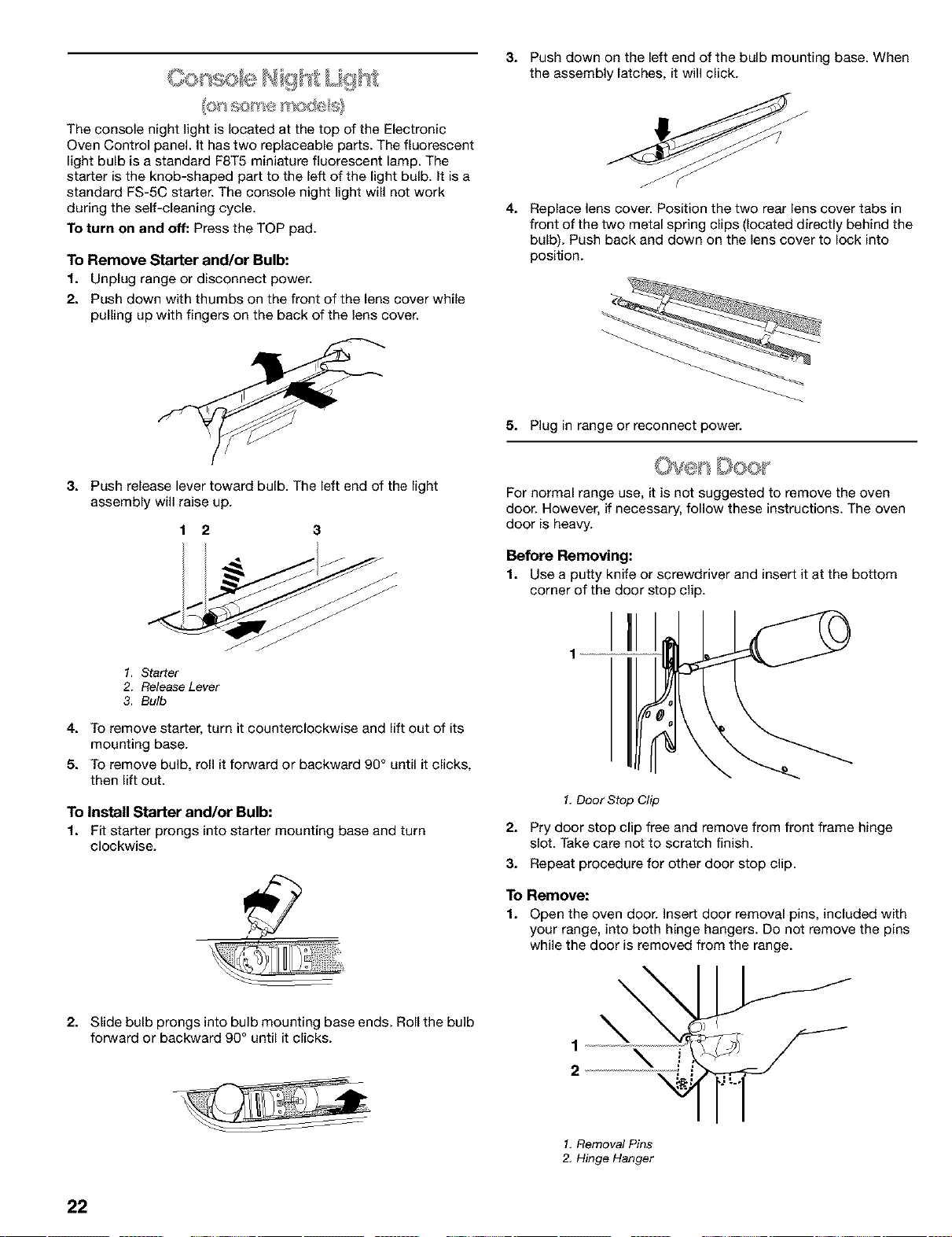
3. Push release lever toward bulb. The left end of the lght
assembly will raise up.
1 2 3
1. Starter
2. Release Lever
3. Bulb
4. To remove starter, turn it counterclockwise and/ft out of its
mounting base.
5. To remove bulb, roll it forward or backward 90 ° until it clcks,
then/ft out.
To Install Starter and/or Bulb:
1. FI starter prongs into starter mounting base and turn
clockwise.
2. Stde bulb prongs into bulb mounting base ends. Rol the bulb
forward or backward 90° until it clcks.
5. Plug in range or reconnect power.
For normal range use, it is not suggested to remove the oven
door. However, if necessary, follow these instructions. The oven
door is heavy.
Before Removing:
1. Use a putty knife or screwdriver and insert it at the bottom
corner of the door stop clip.
I
1
1.DoorStop Clip
2. Pry door stop clip free and remove from front frame hinge
slot. Take care not to scratch finish.
3. Repeat procedure for other door stop clip.
To Remove:
1. Open the oven door. Insert door removal pins, included with
your range, into both hinge hangers. Do not remove the pins
while the door is removed from the range.
\
\
1
\ J
2
\
1. Removal Pins
2, Hinge Hanger
22
Loading ...
Loading ...
Loading ...