Operating Instructions and Parts Manual
MILL
Models: ETM–949 and ETM–949EVS
JET
®
427 New Sanford Road
LaVergne, Tennessee 37086
www.jettools.com
Ph.: 855-336-4032
Part No. M-894010
REV D2 06/2019
Copyright © 2017 JET
This .pdf document is bookmarked

2
MILL
1.0 WARRANTY AND SERVICE
JET
®
warrants every product it sells against manufacturers’ defects. If one of our tools needs service or repair, please
contact Technical Service by calling 1-855-336-4032, 8AM to 5PM CST, Monday through Friday.
WARRANTY PERIOD
The general warranty lasts for the time period specified in the literature included with your product or on the official JET
branded website, jettools.com.
WHO IS COVERED?
This warranty covers only the initial purchaser of the product from the date of delivery.
WHAT IS COVERED?
This warranty covers any defects in workmanship or materials subject to the limitations stated below. This warranty does not
cover failures due directly or indirectly to misuse, abuse, negligence or accidents, normal wear-and-tear, improper repair,
alterations or lack of maintenance.
HOW TO GET TECHNICAL SUPPORT
Please contact Technical Service by calling 1-855-336-4032. Please note that you will be asked to provide proof of initial
purchase when calling. If a product requires further inspection, the Technical Service representative will explain and assist
with any additional action needed. JET has Authorized Service Centers located throughout the United States. For the name
of an Authorized Service Center in your area call 1-855-336-4032 or use the Service Center Locator on the JET website.

3
ETM–949 | ETM–949EVS
MORE INFORMATION
JET
®
is constantly adding new products. For complete, up-to-date product information, check with your local distributor or
visit the JET website, jettools.com.
HOW STATE LAW APPLIES
This warranty gives you specific legal rights, subject to applicable state law.
LIMITATIONS ON THIS WARRANTY
JET LIMITS ALL IMPLIED WARRANTIES TO THE PERIOD OF THE LIMITED WARRANTY FOR EACH PRODUCT.
EXCEPT AS STATED HEREIN, ANY IMPLIED WARRANTIES OF MERCHANTABILITY AND FITNESS FOR A PARTICULAR
PURPOSE ARE EXCLUDED. SOME STATES DO NOT ALLOW LIMITATIONS ON HOW LONG AN IMPLIED WARRANTY
LASTS, SO THE ABOVE LIMITATION MAY NOT APPLY TO YOU.
JET SHALL IN NO EVENT BE LIABLE FOR DEATH, INJURIES TO PERSONS OR PROPERTY, OR FOR INCIDENTAL,
CONTINGENT, SPECIAL, OR CONSEQUENTIAL DAMAGES ARISING FROM THE USE OF OUR PRODUCTS. SOME
STATES DO NOT ALLOW THE EXCLUSION OR LIMITATION OF INCIDENTAL OR CONSEQUENTIAL DAMAGES, SO
THE ABOVE LIMITATION OR EXCLUSION MAY NOT APPLY TO YOU.
JET sells through distributors only. The specifications listed in JET printed materials and on official JET website are given as
general information and are not binding. JET reserves the right to effect at any time, without prior notice, those alterations
to parts, fittings, and accessory equipment which they may deem necessary for any reason whatsoever. JET
®
branded
products are not sold in Canada by JPW Industries, Inc.
NOTE: JET is a division of JPW Industries, Inc. References in this document to JET also apply to JPW Industries, Inc., or
any of its successors in interest to the JET brand.

4
MILL
2.0 TABLE OF CONTENTS
1.0 WARRANTY AND SERVICE .........................................................................................................................................2
2.0 TABLE OF CONTENTS .................................................................................................................................................4
3.0 SAFETY WARNINGS ....................................................................................................................................................5
4.0 INTRODUCTION ...........................................................................................................................................................6
5.0 SPECIFICATIONS .........................................................................................................................................................6
6.0 UNPACKING .................................................................................................................................................................7
6.1 CONTENTS OF THE SHIPPING CONTAINTER ......................................................................................................7
7.0 SET-UP AND INSTALLATION .......................................................................................................................................7
7.1 PREPARING THE MILLING MACHINE FOR SERVICE ..........................................................................................7
8.0 ELECTRICAL CONNECTIONS ...................................................................................................................................11
8.1 GENERAL ELECTRICAL CAUTIONS ....................................................................................................................11
8.2 WIRE SIZES ...........................................................................................................................................................11
8.3 LUBRICATION ........................................................................................................................................................ 11
9.0 OPERATING INSTRUCTIONS ....................................................................................................................................11
9.1 OPERATING CONTROLS ...................................................................................................................................... 11
9.2 MOTOR SWITCH ................................................................................................................................................... 11
9.3 SPEED CONTROL .................................................................................................................................................13
9.4 SPINDLE BRAKE ...................................................................................................................................................13
9.5 HIGH-NEUTRAL-LOW SHIFT LEVER ...................................................................................................................13
9.6 QUILL POWER FEED LEVER ................................................................................................................................13
9.7 FEED RATE LEVER ...............................................................................................................................................14
9.8 FEED TRIP CAM LEVER .......................................................................................................................................14
9.9 FEED DIRECTION CONTROL ...............................................................................................................................15
9.10 COARSE FEED HANDLE ....................................................................................................................................15
9.11 QUILL LOCK LEVER ............................................................................................................................................15
9.12 MICROMETER ADJUSTING NUT ........................................................................................................................15
9.13 FINE FEED HANDWHEEL ...................................................................................................................................15
9.14 DEPTH SCALE AND STOP ..................................................................................................................................16
9.15 POWER FEED OPERATION ................................................................................................................................16
9.16 DRAW BAR OPERATION - CHANGING TOOLING .............................................................................................17
9.17 CLAMPING WORK PIECES TO THE TABLE .......................................................................................................17
10.0 ADJUSTMENTS ........................................................................................................................................................17
10.1 MILL HEAD - LEFT/RIGHT ADJUSTMENT ..........................................................................................................17
10.2 MILL HEAD - FORE/AFT ADJUSTMENT .............................................................................................................18
10.3 POSITIONING THE RAM .....................................................................................................................................19
10.4 GIB ADJUSTMENT ...............................................................................................................................................20
10.5 POWER FEED TRIP LEVER MECHANISM .........................................................................................................20
10.6 TABLE LEAD SCREW BACKLASH ADJUSTMENT .............................................................................................21
10.7 SPINDLE PIN (COLLET RETENTION) ................................................................................................................22
11.0 MAINTENANCE .........................................................................................................................................................23
11.1 LUBRICATION .......................................................................................................................................................23
11.2 PERIODIC MAINTENANCE REQUIREMENTS ....................................................................................................23
12.0 RECOMMENDED SPEED FOR MILL AND DRILL OPERATION ........................................................................24
13.0 REPLACEMENT PARTS ...........................................................................................................................................24
14.0 WIRING DIAGRAM ...................................................................................................................................................48
3.0 SAFETY WARNINGS
1. Read and understand the entire owner’s manual before attempting assembly or operation.
2. Read and understand the warnings posted on the machine and in this manual. Failure to comply with all of these warnings may
cause serious injury. Replace the warning labels if they become obscured or removed.
3. This turret mill is designed and intended for use by properly trained and experienced personnel only. If you are not familiar with the
proper and safe operation of a turret mill, do not use until proper training and knowledge have been obtained.
4. Do not use this turret mill for other than its intended use. If used for other purposes, JET
®
, disclaims any real or implied warranty
and holds itself harmless from any injury that may result from that use.
5. Always wear approved safety glasses/face shields while using this turret mill. (Everyday eyeglasses only have impact resistant
lenses; they are not safety glasses.)
6. Before operating this turret mill, remove tie, rings, watches and other jewelry, and roll sleeves up past the elbows. Remove all
loose clothing and confine long hair. Non-slip footwear or anti-skid floor strips are recommended. Do not wear gloves.

5
ETM–949 | ETM–949EVS
7. Wear ear protectors (plugs or muffs) during extended periods of operation.
8. Do not operate this machine while tired or under the influence of drugs, alcohol or any medication.
9. Make certain the switch is in the OFF position before connecting the machine to the power supply.
10. Make certain the machine is properly grounded.
11. Make all machine adjustments or maintenance with the machine unplugged from the power source.
12. Remove adjusting keys and wrenches. Form a habit of checking to see that keys and adjusting wrenches are re-moved from the
machine before turning it on.
13. Keep safety guards in place at all times when the machine is in use. If removed for maintenance purposes, use extreme caution
and replace the guards immediately.
14. Some coolants used for machining contain chemicals that may be hazardous to your health if not used properly. Read and
understand all information on the coolant container and protect yourself accordingly.
15. Check damaged parts. Before further use of the machine, a guard or other part that is damaged should be carefully checked to
determine that it will operate properly and perform its intended function. Check for alignment of moving parts, binding of moving
parts, breakage of parts, mounting and any other conditions that may affect its operation. A guard or other part that is damaged
should be properly repaired or replaced.
16. Do not use power tools in damp/wet locations or other dangerous environments. Do not expose them to rain. Keep work area well
lighted. Provide for adequate space surrounding work area and non-glare, overhead lighting.
17. Keep work area and the floor around the machine clean and free of scrap material, oil and grease.
18. Keep visitors a safe distance from the work area. Keep children away. Workshop should be childproof; padlocks, master switches,
remove starter keys.
19. Give your work undivided attention. Looking around, carrying on a conversation and “horse-play” are careless acts that can result
in serious injury.
20. Maintain a balanced stance at all times so that you do not fall or lean against the cutters or other moving parts. Do not overreach
or use excessive force to perform any machine operation.
21. Use the right tool at the correct speed and feed rate. Do not force a tool or attachment to do a job for which it was not designed.
The right tool will do the job better and more safely.
22. Use recommended accessories; improper accessories may be hazardous.
23. Maintain tools with care. Keep cutters sharp and clean for the best and safest performance. Follow instructions for lubricating and
changing accessories.
24. Turn off the machine and disconnect from power before cleaning. Use a brush or compressed air to remove chips or debris — do
not use your hands.
25. Do not stand on the machine. Serious injury could occur if the machine tips over.
26. Never leave the machine running unattended. Turn the power off and do not leave the machine until it comes to a complete stop.
27. Remove loose items and unnecessary work pieces from the area before starting the machine.
28. Clamp workpiece or brace against column to prevent rotation. For safety and use of both hands, use clamps or a vise to hold work
when practical.
29. Use recommended speed for drill accessory and workpiece material.
30. Direction of feed — feed work into a blade or cutter against the direction of rotation of the blade or cutter only.
31. Installation work and electrical wiring must be done by qualified electrician in accordance with all applicable codes and standards.
WARNING: This product can expose you to chemicals including lead which is known to the State of California to cause cancer
and birth defects or other reproductive harm, and ethylbenzene which is known to the State of California to cause cancer. For
more information go to http://www.p65warnings.ca.gov.
WARNING: Some dust, fumes and gases created by power sanding, sawing, grinding, drilling, welding and other construction
activities contain chemicals known to the State of California to cause cancer and birth defects or other reproductive harm. Some
examples of these chemicals are:
lead from lead based paint
crystalline silica from bricks, cement and other masonry products
arsenic and chromium from chemically treated lumber
Your risk of exposure varies, depending on how often you do this type of work. To reduce your exposure to these chemicals, work
in a well-ventilated area and work with approved safety equipment, such as dust masks that are specifi cally designed to fi lter out
microscopic particles. For more information go to http://www.p65warnings.ca.gov/ and http://www.p65warnings.ca.gov/wood.
6
MILL
4.0 INTRODUCTION
This manual is provided by JET
®
covering the safe operation and maintenance procedures for a JET Model ETM-949 and
ETM-949EVS. This manual contains instructions on installation, safety precautions, general operating procedures, mainte-
nance instructions and parts breakdown. Your machine has been designed and constructed to provide years of trouble-free
operation if used in accordance with the instructions as set forth in this document.
If there are questions or comments, please contact your local supplier or JET. JET can also be reached at our web site:
www.jettools.com. Retain this manual for future reference. If the machine transfers ownership, the manual should accom-
pany it.
5.0 SPECIFICATIONS
Model Number
ETM-949, ETM-949EVS,
ETM-949EVS-Type 2
Stock Number
894010, 894050,894050-1
Table Size (LxW) (in.) 9 x 49
Spindle Taper (in. x TPI) R-8
Quill Diameter (in.) 3-3/8
Number of Spindle Speeds Variable
Range of Spindle Speeds (RPM) 60-4500 / 60-5000
Quill Down Feed Rates (IPR) .0015-.003-.006
Spindle Travel (in.) 5
Head Movement (deg.) R90° & L45° F&B
Max Distance Spindle to Table (in.) 18-3/4
Distance Spindle to Column (max. in.) 21-2/5
Distance Spindle to Column (min. in). 6
Collet Capacity
1/8-7/8
Table Longitudinal Travel (in.) 36
Table Cross Travel (in.) 12
T-Slots Number and Size (in.) 3 and 5/8
T-Slot Centers (in.) 2-1/2
Work Table Weight Capacity (lbs.) 750
Travel of Knee (in.) 16
Travel of Ram (in.) 14
Motor (HP)
3 HP, 230V 3Ph
CSA/CUS Certified
Inverter E type, 230V 3Ph
Overall Dimensions (LxWxH) (in.) 64 x 66 x 84
Net Weight (lbs.) 2420
Gross Weight (lbs.) 2420
Familiarize yourself with the following safety notices used in this manual:
The specifications in this manual were
current at time of publication, but because
of our policy of continuous improvement,
JET, reserves the right to change
specifications at any time and without
prior notice, without incurring obligations.
!
This means that if precautions are not heeded, it
may result in minor injury and/or possible machine
damage.
!
This means that if precautions are not heeded, it
may result in serious or even fatal injury.
7
ETM–949 | ETM–949EVS
6.0 UNPACKING
Open shipping container and check for shipping damage.
Report any damage immediately to your distributor and
shipping agent. Do not discard any shipping material until
the Turret Mill is assembled and running properly.
Compare the contents of your container with the following
parts list to make sure all parts are intact. Missing parts,
if any, should be reported to your distributor. Read the
instruction manual thoroughly for assembly, maintenance
and safety instructions.
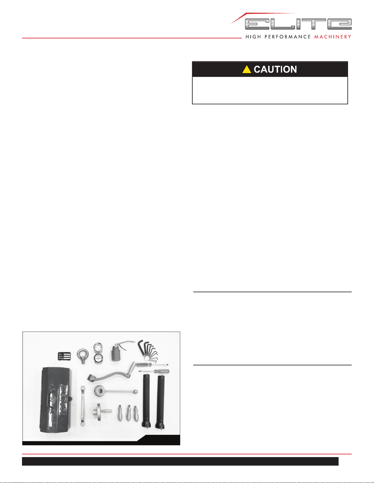
6.1 CONTENTS OF THE SHIPPING CONTAINER
Note: Some parts may be pre-installed on the mill.
1 Turret Mill (not shown)
1 Flat Way Cover
1 Pleated Way Cover
1 Draw Bar
3 Table Adjustment Handles
1 Tool Box, containing:
1 Hex Key Set (1.5-10mm) *
1 17/19mm Box Wrench *
1 Cross Point Screw Driver #2 *
1 Flat Blade Screw Driver #2 *
1 Oil Can *
1 Elevating Crank Handle
1 Handwheel
1 Coarse Feed Handle
1 Can Silver Touch Up Paint
1 Can Black Touch Up Paint
1 Eye Bolt
1 Operator’s Manual (not shown)
1 Warranty Card (not shown)
* parts with an asterisk are also included in the tool box
service kit, p/n ETM-949/EVS.
Fig. 1
!
Read and understand the entire contents of this
manual before attempting set-up or operation!
Failure to comply may cause serious injury.
If your mill is supplied with an optional Table Powerfeed
and/or DRO, be sure to consult the separate instruction
materials that accompany them.
7.0 SET-UP AND INSTALLATION
7.1 PREPARING THE MILLING MACHINE FOR
SERVICE
1. Remove any crating which may be covering the ma-
chine on the pallet.
2. Remove accessory items from the pallet or machine
table. Compare these items with the list on the
previous page.
3. Check the tightness of the lifting ring on the ram to be
certain it is tight.
4. Check the tightness of the lock handles on the ram
(see Figure 23) to be certain the ram is locked tight.
5. Remove the nuts and/or bolts, which secure the ma-
chine to the pallet.
6. Center an overhead crane or other suitable overhead
lifting device and sling arrangement over the lifting
ring.
Note: This machine weighs over 2400 pounds! Be
certain the lifting arrangement is new or in excellent
condition and has a safety factor that will account for
age, difficulties in lifting, etc. When lifting using the
ring, the machine will tip forward. If you wish, you can
minimize this tipping by rigging a support sling over
the front of the machine. Be careful when doing this,
to prevent the sling from damaging any components
on the front of the machine. Be sure to steady the mill
to prevent it from spinning.
7. Lift the machine off the pallet no higher than neces-
sary to clear the hold-down hardware, then pull
the pallet out of the way. Do NOT get hands or feet
underneath the machine when removing the pallet!
8. Put the machine base over the hold-down system
where the machine will be spotted. Anchor bolts of
sufficient size and length must be fastened to the floor
according to the footprint of the mill. See diagram on
page 9.

8
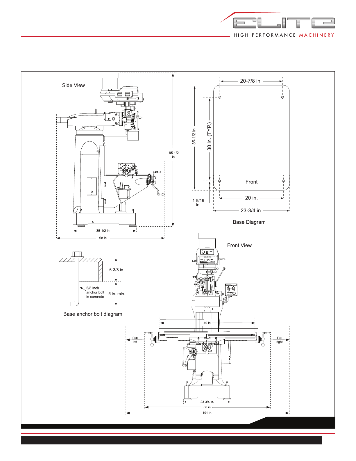
MILL
Note: The accompanying diagrams show you the max-
imum dimensions of the machines with the table, ram,
etc., fully extended in all possible directions. When
spotting the machine be certain to leave room not only
for the machine itself, but also for operator clearance
and clearance for workers servicing the machine, and
any unusual sizes of workpieces that might extend off
the machine’s table.
9. When the machine is over its anchors, level the ma-
chine using shims under the corners needing them.
The machinist’s level used for leveling should be
placed on the table. The table is the reference surface
for both side-to-side and fore-and-aft leveling. Be cer-
tain you get it level in BOTH directions.
10. When the machine is level, secure the base to the
anchor system.
IMPORTANT: Before attempting to raise the mill head,
refer to Mill Head – Left/Right Adjustment in the Adjust-
ments section for procedures to safely raise and set up
the mill head.
11. Loosen the four hex head nuts (see A, Figure 20)
about 1/4 turn each (counterclockwise), just enough to
allow rotation of the head.
12. While assisting the worm mechanism by putting
upward pressure on the motor by hand, use the
wrench supplied with the machine to turn the worm nut
and raise the head to upright position.
13. Tighten the headbolts slightly — not torqued — just
snug.
14. Using mineral spirits or other cleaning solvent, clean
all of the rust proofing from where it may have been
applied. This is important; moving the table or any
other components before removing the rust proofing
will only put rust proofing where you don’t want it.
!
Mill must be supported equally under all four
corners. Failure to comply may cause the column to
twist and put a bind in the table ways.
Some of the following steps may have already been per-
formed on the machine. If so, ignore the instructions related
to those particular steps. Otherwise, perform them in the
order listed, referring to Figure 9 for any clarification.
15. Install the table traverse and cross-feed cranks on
their respective shafts using the nuts on the shafts to
secure the cranks.
16. Remove any rust proofing from the drawbar and its
washer, and put the drawbar with washer installed into
the spindle center through the top of the machine.
17. Slide the fine feed handwheel over the handwheel hub
and push it back until its rollpin engages the hole in
the hub and the wheel is flush with the hub surface.
18. Put the coarse feed handle on the feed shaft and tap
it lightly until its roll pin engages a hole in the hub and
it is flush against the hub surface.
19. Unwrap and clean the knee crank and install it on its
shaft.
20. Install the rubber way covers at front and behind the
table.
9
ETM–949 | ETM–949EVS
Fig. 2
ETM–949 DIMENSIONS
10
MILL
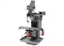
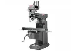
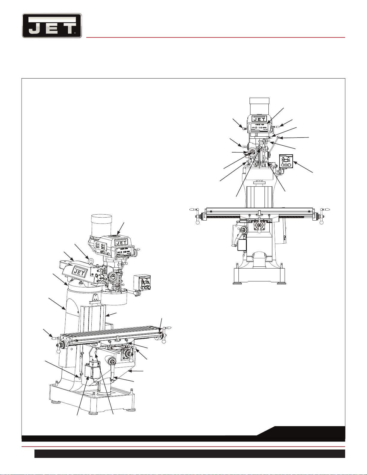
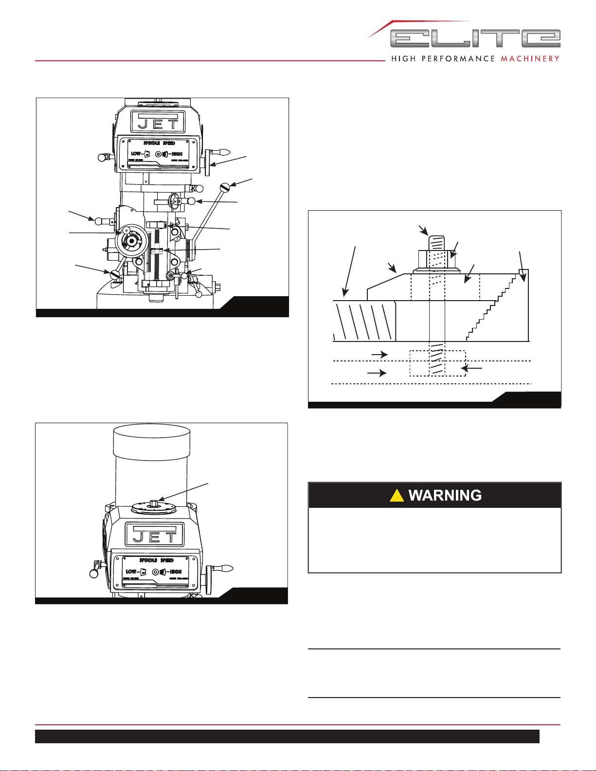
Fig. 3
ETM–949 OVERVIEW AND TERMINOLOGY
Head Assembly
Lifting Ring
Ram
Turret
Column
Longitudinal
Crank (2)
Knee Locking
Handle (2)
Knee Crank
Knee
Crossfeed
Crank
Table Locking
Handle (2)
Table Stop
Flat Way Cover
Auto Lubricator
Saddle Locking Handle
Spindle Brake
Motor Switch
Feed Rate Lever
Fine Feed Handwheel
Feed Direction
Control
Feed Trip Cam
Lever
Quill Stop
Quill Locking
Lever
Power Feed Lever
Coarse Feed
Handle
Hi/Lo Shift Lever
Vari-Speed Handwheel
Speed Range Panel
11
ETM–949 | ETM–949EVS
8.0 ELECTRICAL CONNECTIONS
8.1 GENERAL ELECTRICAL CAUTIONS
This machine must be grounded in accordance with the
National Electrical Code and local codes and ordinances.
This work should be done by a qualified electrician. The
machine must be grounded to protect the user from electri-
cal shock.
8.2 WIRE SIZES
To minimize power losses and to prevent motor overheat-
ing and burnout, the use of wire sizes for branch circuits or
electrical extension cords according to the following table
is recommended:
Conductor Length
AWG Number
230/460 Volt
Lines
120 Volt Lines
0 – 50 Ft. No. 14 No. 14
50 – 100 Ft. No. 14 No. 12
Over 100 Ft. No. 12 No. 8
Confirm that power at the site matches power require-
ments of the mill before connecting to the power source.
The ETM-949 has been pre-wired for 230 volt operation.
Before connecting to the power source, make sure that the
switch is in the off position.
The mill must be properly grounded.
Check for proper spindle rotation in the high-speed range.
The spindle should rotate clockwise when viewed from the
top of the machine. If the spindle rotates counter-clock-
wise, disconnect from power and switch two of the three
power leads.
!
All electrical connections must be made by a
qualified electrician! Failure to comply may cause
serious injury!
!
For circuits which are far away from the electrical
service box, the wire size must be increased in
order to deliver ample voltage to the motor.
Table 1
8.3 LUBRICATION
Refer to the Maintenance/Lubrication section and make
sure the machine has been fully lubricated before operat-
ing.
9.0 OPERATING INSTRUCTIONS
9.1 Operating Controls
The milling machine is equipped with an automatic lubrica-
tion system. Ensure that reservoir has the proper amount
of lubricant. The system reservoir is located on the left
side of the machine on the knee.
The position of the milling machine mill head can be set
up to accommodate the work piece being machined. The
mill head can be set up for angles to the left or right and
for fore and aft angles. The mill head can also be rotated
on its turret. The ram can be moved back and forth to
reach work piece locations at the fore and aft extremes of
worktable travel. Refer to the Adjustments section.
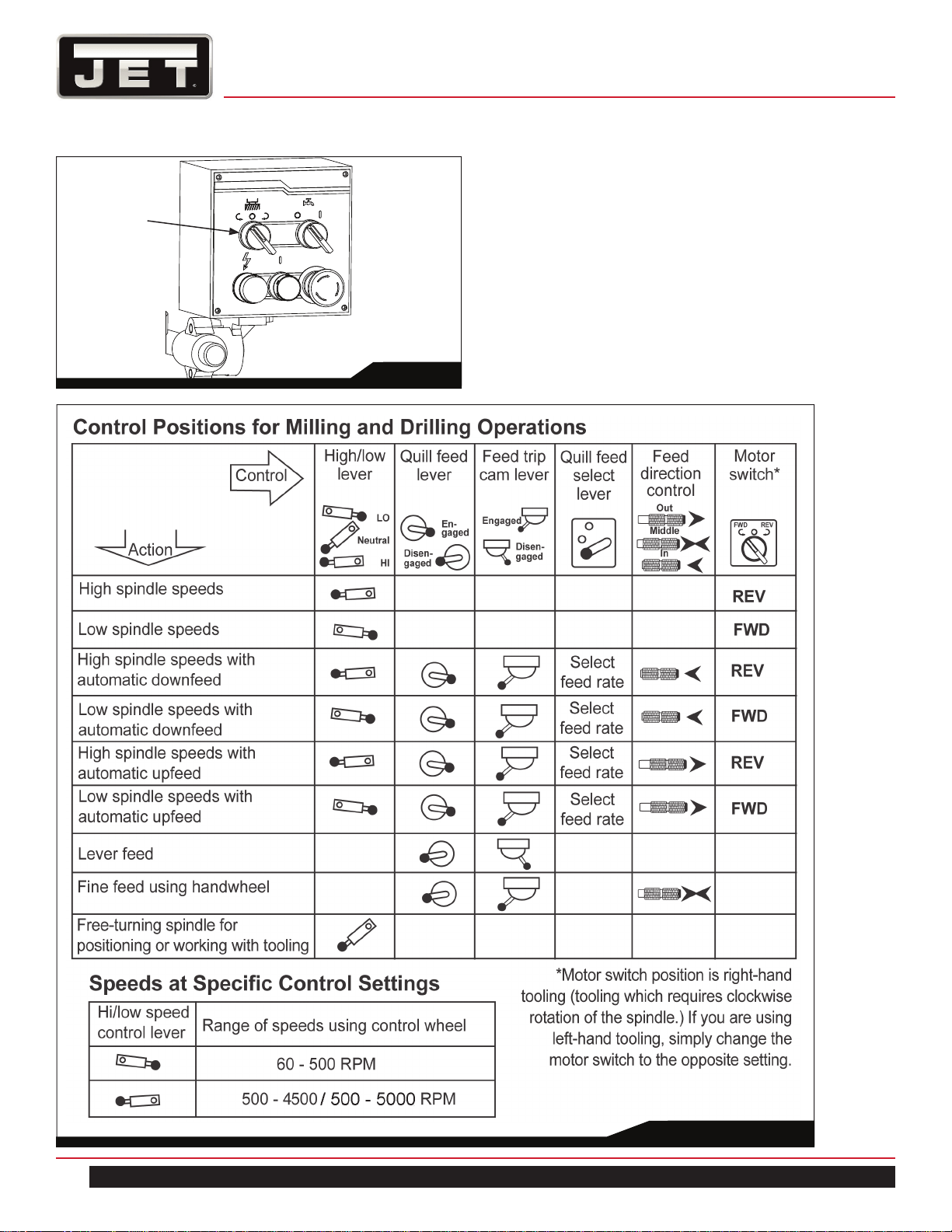
9.2 Motor Switch
The Motor Switch is located on the right side of the
machine on the control panel arm. The switch has two
positions: FWD (forward) and REV (reverse).
Setting the switch to FWD will provide clockwise spindle
rotation. Use FWD for normal, right-hand tooling.
FWD (clockwise) operation occurs only when the gear-
box is in the low speed position. When the gearbox is in
high-speed position, the motor switch must be in the REV
position to provide right-hand or clockwise rotation. Refer
to Figure 5 for a chart of required switch positions.
The motor switch controls a three-phase motor. The motor
can be switched from FWD to REV and back with the
motor running, and will reverse direction when the switch
setting is changed. At higher speeds, this may put strain
on the timing belt but there will be no damage to the motor
or gear mechanism.
!
Do not operate the mill before lubricating the
machine fully. Failure to comply may cause damage
to the machine.
12
MILL
Fig. 5
Fig. 4
Motor Switch
13
ETM–949 | ETM–949EVS
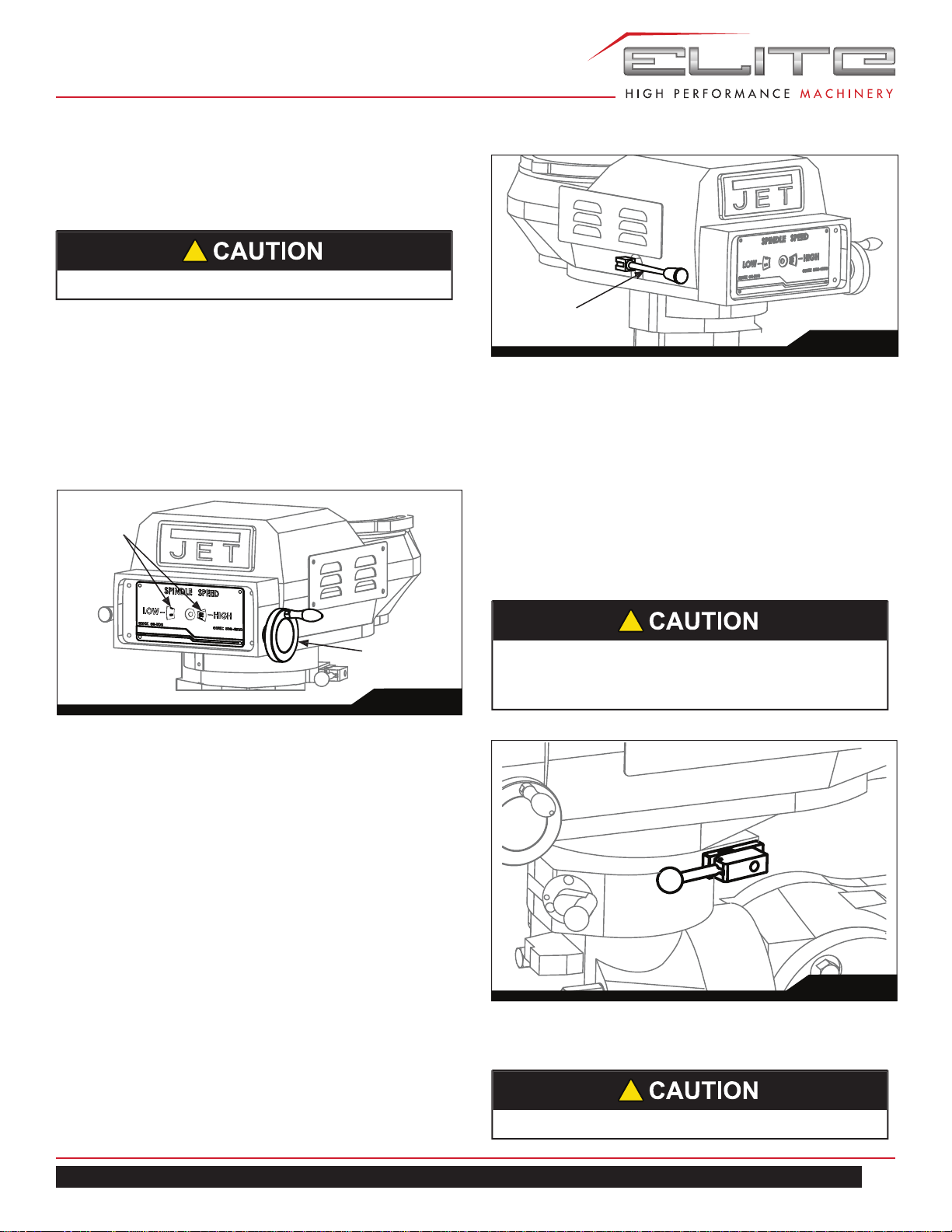
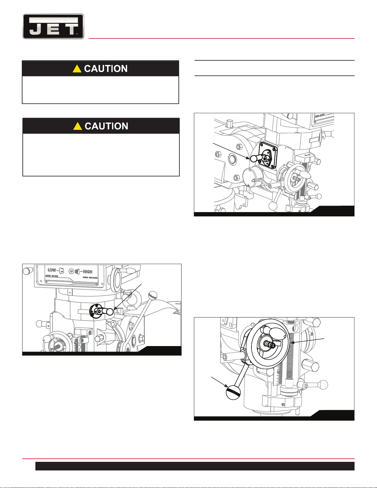
9.3 SPEED CONTROL
9.3.1 VARIABLE SPEED CONTROL
The vari-speed handwheel (A, Figure 6) is used to control
the spindle speed. The speeds for high and low speed
ranges are displayed on the panel on the front of the mill
head (B, Figure 6).
All speed changes must be made while the motor is run-
ning. Attempting speed changes without the motor running
can result in damage to the drive mechanism.
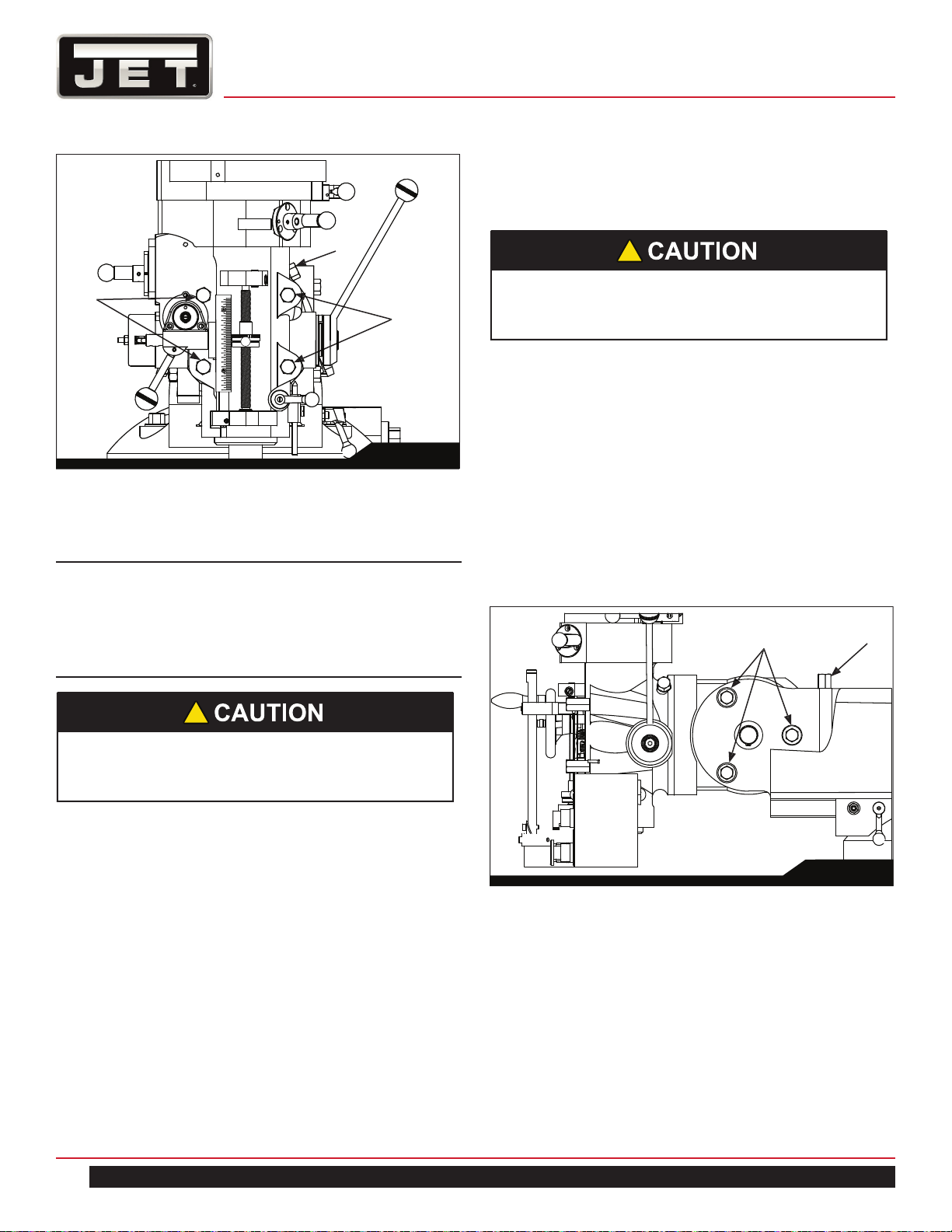
9.4 SPINDLE BRAKE
The spindle brake lever is located on the upper left side of
the mill head (Figure 7). Pull lever downward to apply the
brake. The spindle brake is also equipped with a power cut
off microswitch. When the brake is applied, the power to
motor is also disengaged.
!
Change speed only while the spindle is turning.
9.5 HIGH-NEUTRAL-LOW SHIFT LEVER
The mill head can be driven directly (High Speed) or
through the back gear (Low Speed) in the mill head. The
selection is made by changing the position of the shift
lever.
The shift lever is located at the lower right side of the mill
head (Figure 8). The lever position closest to the operator
is the High setting. The lever position away from the oper-
ator is the Low setting. The middle position is the Neutral
setting.
9.6 QUILL POWER FEED LEVER
!
Do not shift the High-Low Gear Lever while the mo-
tor is running. Rotate the spindle by hand to facili-
tate changing lever positions.
Fig. 8
!
Do not use power feed at speeds above 3000 R.P.M.
9.3.2 ELECTRONIC VARIABLE SPEED
The dial on the EVS control panel controls the main mo-
tor speed. Motor rpm is displayed on the display screen.
When in low gear, the light beside display 1 will be illumi-
nated. When in high gear the light beside display 2 will be
illuminated.
Fig. 6
B
A
Fig. 7
Brake Lever
14
MILL
The quill power feed lever is located on the right side of
the mill head (Figure 9). It is used to engage and disen-
gage the quill power feed mechanism.
The power feed is engaged by pulling out the knob and ro-
tating the handle to a new locked position. When engaged,
the power feed mechanism will drive the spindle upward or
downward. The power feed mechanism will not drive the
spindle when the handle is in the disengage position.
9.7 FEED RATE LEVER
The Feed Rate Lever (Figure 10) is used to set the
per-revolution rate of the power feed mechanism. Three
feed rates are available: 0.0015-inch, 0.003-inch, and
0.006-inch per revolution. The positions are shown on an
indicator plate under the feed rate lever.
The rate is selected by pulling out the knob on the feed
rate lever and moving the handle to the detent of the de-
sired feed rate.
Do not move the Quill Power Feed Lever unless
the motor is at a complete stop. When changing
the lever position, do it gently. If the gear does not
engage, jog the motor and allow it to stop before
attempting to change.
!
Fig. 9
9.8 FEED TRIP CAM LEVER
The Feed Trip Cam Lever (A, Figure 11) is located on
the left side of the head behind the Manual Fine Feed
Handwheel (B, Figure 11). It engages the overload clutch
on the pinion shaft when positioned to the left. The Feed
Trip Cam Lever stays engaged until Quill Stop (C, Figure
14) comes in contact with Micrometer Adjusting Nut (A,
Figure 14) forcing it to drop out automatically, or until it is
released manually by engaging the lever to the right.
!
It is recommended to disengage the power feed
worm gear whenever the power feed is not required.
This avoids unnecessary wear on the worm gear.
Note: The knob is spring loaded – pull out to rotate to
new position.
Unlike other controls on the machine, the lever shifts into
engagement more easily with the motor running, and the
quill feed lever engaged.
Quill Power Feed
Lever
Fig. 11
A
B
Fig. 10
Feed
Rate
Lever
15
ETM–949 | ETM–949EVS
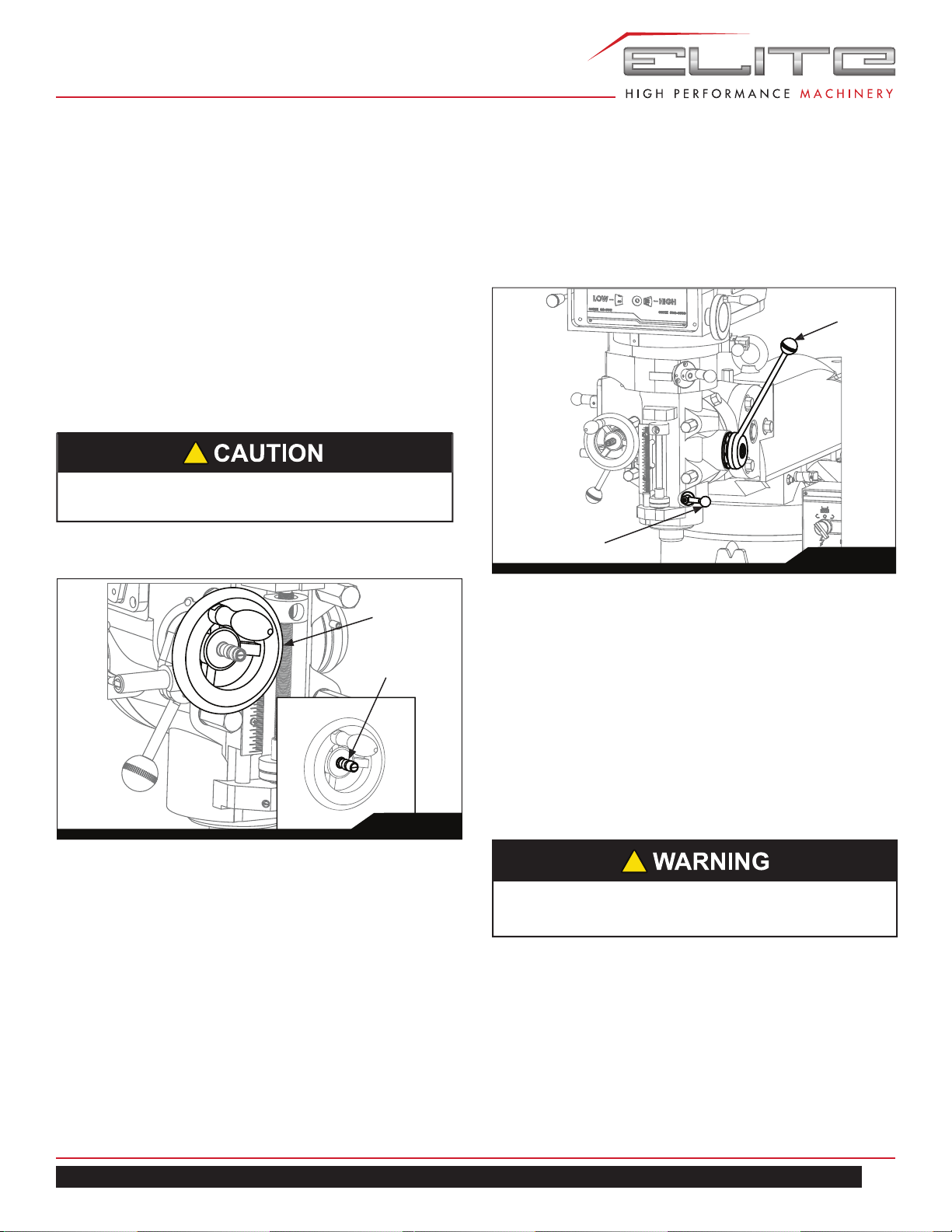
9.9 FEED DIRECTION CONTROL
The Feed Direction Control (B, Figure 12) determines
whether the power feed will move up, down, or not move
at all. The position of the knob depends upon the direction
of spindle rotation (see the Motor Switch section). The
position of the control may be changed with the system
stopped or running. If the control does not engage easily,
move the fine feed handwheel (A, Figure 12) back and
forth to aid engagement.
If the spindle is rotating clockwise, in is downfeed; out is
upfeed. If the spindle rotation is counterclockwise, out is
downfeed; in is upfeed. Neutral position is between the in
and out position.
9.10 COARSE FEED HANDLE
The Coarse Feed Handle (A, Figure 13) is located on the
right side of head. The Coarse Feed Handle is used for
non-precision drilling operations and for moving the quill
to a specific depth. A return spring will retract the spindle
automatically once the handle is released.
It is recommended that the Feed Direction Knob be
left in the neutral position when not in use.
!
9.11 QUILL LOCK LEVER
The Quill Lock Lever (B, Figure 13) is located on the right
side of the head. Rotate the handle clockwise to lock the
quill in a desired position. Rotate the handle counter-clock-
wise to release.
9.12 MICROMETER ADJUSTING NUT
The Micrometer Adjusting Nut (A, Figure 14) is located
on the front of the head. Use for setting specific spindle
depth.
9.13 FINE FEED HANDWHEEL
When the controls are set for the Fine feed using Hand-
wheel position (see Figure 5), the Fine Feed Handwheel
(A, Figure 12) can be used for manual fine feed control in
either upward or downward direction of the quill.
!
Remove the Manual Fine Feed Handwheel when not
in use. Failure to comply may cause serious injury.
Fig. 13
B
A
Fig. 12
A
B
16
MILL
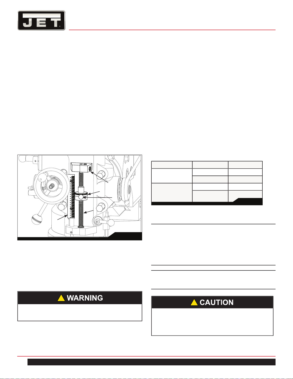
9.14 DEPTH SCALE AND STOP
Referring to Figure 14:
The Depth Scale and Stop are used in drilling operations
to set the depth of the drilled hole. The depth scale is
located on the front of the mill head. The scale consists of
a Micrometer Adjusting Nut (A), Micro-nut quick adjust (B),
Quill Stop (C), Quill Stop Screw (D), and Scale (E).
The Micrometer Adjusting Nut is set to the desired di-
mension and is held in place by the friction applied by the
micro-nut quick adjust. The quill stop provides a positive
stop for quill travel.
The graduations on the micrometer nut are in 0.001 inch
increments. Adjustment of quill travel is made by rotat-
ing the micrometer nut, or by pressing the micronut quick
adjust button and sliding the nut up or down.
9.15 POWER FEED OPERATION
The Feed Trip Adjustment sets the point at which the quill
will reset during Power Feed.
Referring to Figure 15:
1. Move adjuster nut to allow for ample spindle travel.
2. With the Quill Feed Handle (J), advance the quill to
the point where the feed should stop.
3. Engage the Feed Trip Cam Lever (D) by pulling away
from head assembly.
4. Adjust Micrometer Adjusting Nut (H) against Quill Stop
(G).
5. Continue turning the Micrometer Adjusting Nut (H)
until the Feed Trip Cam Lever (D) trips.
6. Ensure Quill Lock (K) is disengaged by rotating count-
erclockwise.
7. Start the spindle (See Fig. 5):
8. Select feed rate with the Variable Speed Control
Handwheel (E).
9. Set the Feed Rate Lever (B) to the feed rate required
for the tooling and material required.
10. Place the Quill Feed Engagement Lever (F) in the
Engaged position.
11. Select feed direction by setting the Feed Direction
Knob (C) position per the table:
Spindle Direction Feed Direction Knob Position
CW
Down In
Up Out
CCW
Down Out
Up In
12. Engage the Feed Trip Cam Lever (D) by pulling away
from head assembly.
Note: Due to variables in tool diameter, coatings,
coolant, and materials, no specific spindle speed or
feed rate recommendations are provided. Use general
shop manuals that have data applicable to the milling
and drilling operations being performed. Or, contact
the supplier of the tooling, coolant, and material for
specific recommendations.
IMPORTANT: The power feed can be used for drills up
to 3/8” in diameter (mild steel). Use manual feed for
drills larger than 3/8”.
Be sure that the Manual Fine Feed Handwheel is re-
moved. Failure to comply may cause serious injury.
!
The overload clutch is factory set to hold up to 200
lbs. downfeed pressure on the quill (accommodates
drills up to 3/8”). Do not attempt to adjust clutch
pressure.
!
Table 2
Fig. 14
E
D
A
C
B
17
ETM–949 | ETM–949EVS
9.16 DRAW BAR OPERATION - CHANGING
TOOLING
1. Using the wrench provided with the machine, loosen
the draw bar two or three turns (turn counterclockwise)
using the draw bar hex (Figure 16).
2. Tap the top of the draw bar with a soft-faced hammer
to loosen the collet from the taper.
3. Remove the tool from the collet.
4. Insert the tool you are going to use into the collet.
5. Tighten the draw bar firmly using the wrench provided
with the machine. Turn the draw bar. The tool is now
ready for use.
9.17 CLAMPING WORK PIECE TO THE TABLE
1. The worktable has 5/8-inch T-slots for clamping the
work piece to the table.
2. Set motor switch to STOP position.
3. Place the work piece on the table.
4. Clamp the work piece using the T-slot clamps, studs,
and step blocks as required (Figure 17).
10.0 ADJUSTMENTS
10.1 MILL HEAD – LEFT/RIGHT ADJUSTMENT
1. Loosen four large hex nuts that secure the mill head
to the ram adapter (refer to Figure 18).
1/4 turn should be sufficient to allow the head to
move.
NOTE: For angles greater than 10 degrees, use your
free hand to support the mill head, taking some weight
off the brass worm gears. Doing so will greatly length-
en the life of the worm gears.
Workpiece
Clamp stud
Clamp
nut
Clamp
support
Stud
slot
Tabl e
Tabl e
T-slot
Clamp stud
T-slot block
Typical T-slot Clamp Set-up
Fig. 17
!
Make sure the machine base is secured to the floor
before repositioning the mill head. The center of
gravity can shift enough to cause the machine to tip
over, resulting in serious injury to the operator and
damage to the machine.
Fig. 16
Drawbar Hex
Fig. 15
E
J
F
G
H
K
B
C
D
18
MILL
10. Recheck perpendicularity using the dial indicator.
Repeat the procedure above until the dial indicator
reads zero in both positions.
11. Tighten the four hex nuts. Tighten in two steps using
a calibrated torque wrench. Use a crossing pattern
to tighten the nuts. Tighten initially to 25 foot-pounds,
then tighten to a final torque of 50 foot-pounds.
10.2 MILL HEAD – FORE/AFT ADJUSTMENT
1. Setting the angle:
a. Loosen the three ram adapter clamp bolts on the
ram (A, Figure 19). There is no need to loosen the
bolts more than 1/2 turn to allow tilting.
b. Support the mill head with your free hand. Press
upward on the spindle when changing the angle.
c. Turn the ram adapter worm nut (B, Figure 19) to tilt
the head forward and backward. Use the scale on the
ram adapter to locate the desired angle.
2. Returning to upright position:
a. When returning the mill head to its full upright posi
tion, be sure to support the head by upward pressure
on the spindle as you turn the worm nut.
b. Check to make sure the mill head is perpendicular
to the worktable.
2. Turn the worm nut (B, Figure 18) to tilt the head left or
right as required. Use the scale on the ram adapter to
set the desired angle.
Note: The scales on the ram adapter and for head rota-
tion are guides only. Close tolerance work will require
the use of a dial indicator to make sure the head is 90°
to the table in the X and Y axis. Please note the table
is fitted to be slightly higher in front, usually about
0.0005”.
3. Tighten the four hex nuts. Tighten in two steps using
a calibrated torque wrench. Use a crossing pattern to
tighten the nuts. Tighten initially to 25 foot-pounds.
4. Before applying final torque, check to make sure the
mill head is perpendicular to the worktable.
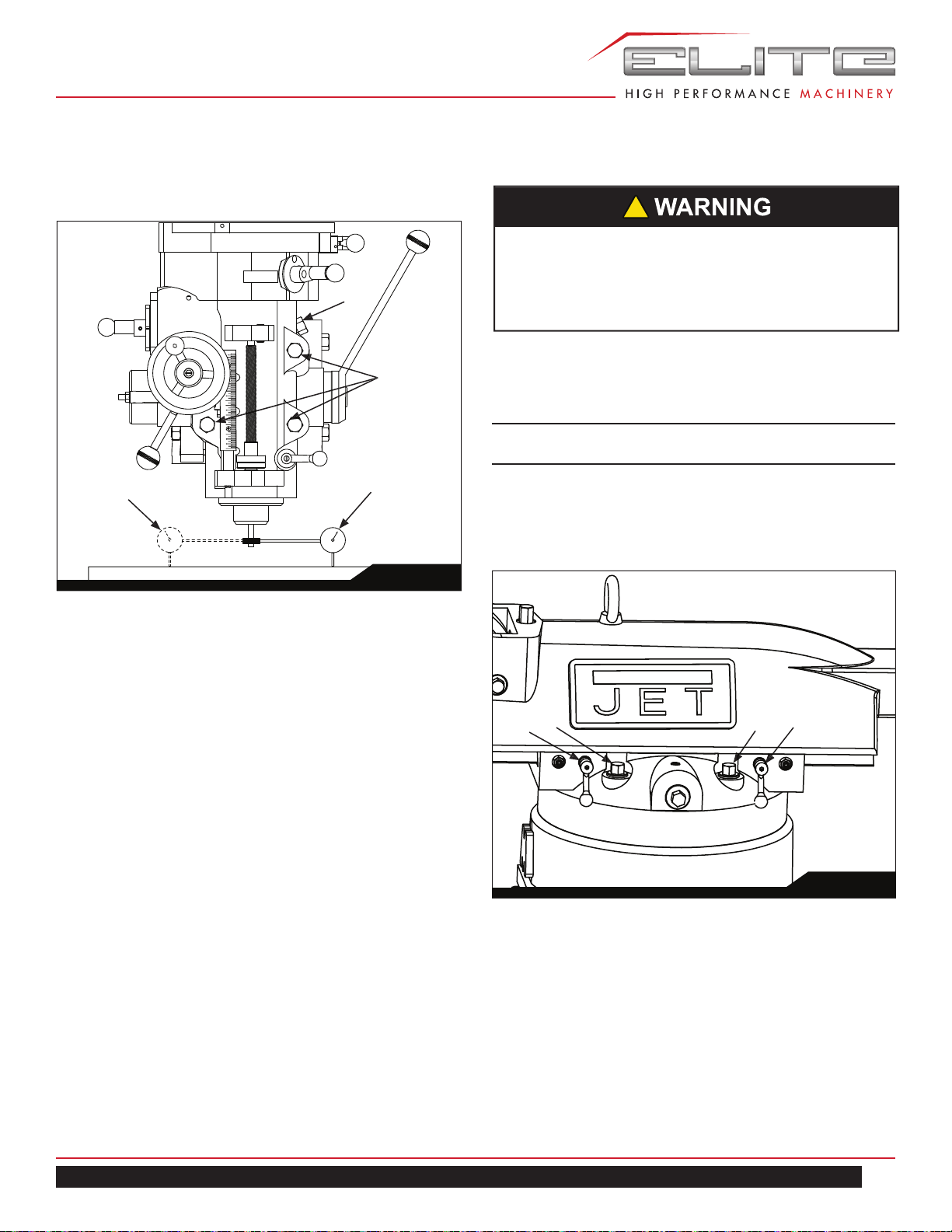
5. Set up a dial indicator in a collet and secure using the
draw bar (refer to Figure 20).
6. Put the spindle drive in neutral.
7. Set the dial indicator plunger on the worktable. Zero
the indicator.
8. Rotate the spindle 180 degrees (when rotating, raise
the dial indicator plunger by hand to prevent it from
dropping into the table T-slots).
9. Read the dial indicator. The indicator should read
zero. If not, loosen the four hex nuts and reposition the
mill head.
!
Be sure to apply torque in two steps using a cross-
ing pattern. Failure to do so could distort the face
of the ram adapter.
Be sure to apply torque in two steps using a cross-
ing pattern. Failure to do so could distort the face
of the ram adapter.
!
Fig. 18
B
A
A
Fig. 19
B
A
19
ETM–949 | ETM–949EVS
c. Set up a dial indicator in a collet and secure using
the draw bar (refer to Figure 20).
d. Put the spindle drive in neutral.
e. Set the dial indicator plunger on the worktable.
Zero the indicator.
f. Rotate the spindle 180 degrees (when rotating, raise
the dial indicator plunger by hand to prevent it from
dropping into the table T-slots).
g. Read the dial indicator. The indicator should read
zero. If not, loosen the four hex nuts and reposition the
mill head.
h. Recheck perpendicularity using the dial indicator.
Repeat the procedure above until the dial indicator
reads zero in both positions.
i. When the indicator reads zero, tighten the ram
adapter clamp bolts.
10.3 POSITIONING THE RAM
Positioning the Ram Fore and Aft:
1. Loosen the two bolts (A, Figure 21) that lock the ram
to its ways.
2. Turn the lever (B, Figure 21) to move the ram on its
ways.
3. When the desired position is reached, lock the bolts
(A, Figure 21) securely.
Positioning the Ram on its Turret:
1. Loosen four turret lock bolts (C, Figure 21) that clamp
the ram to the top of the base. 1/2 turn should be
sufficient to allow the turret to move.
Note: Use gentle hand pressure to avoid rapid move-
ment.
2. Turn the ram until the spindle is in the desired posi-
tion. Use the scale on the turret for degree measure-
ment.
3. Tighten the four turret lock bolts (C. Figure 21).
!
Make sure the machine base is secured to the floor
before repositioning the ram. The center of gravity
can shift enough to cause the machine to tip over,
resulting in serious injury to the operator and dam-
age to the machine.
Fig. 20
B
A
D
C
Fig. 21
C
C
A
A
20
MILL
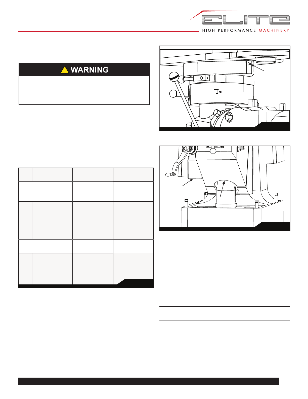
10.4 GIB ADJUSTMENT
The table, saddle and knee are equipped with adjustable
gibs. The gibs may require adjustment if unusual vibration
is noted when the locking mechanisms are off, or if you ex-
perience unusual vibration when spindle speed, tooth pitch
or depth of cut do not account for the vibration.
NOTE: When adjusting gibs, always start with the knee
first; adjust the saddle second, and adjust the table
last.
Adjustment of Knee Gib:
The knee gib adjustment screw (A, Figure 22) is located
under the chip wiper at the rear of the knee where it con-
tacts the column. Remove the way cover and the wiper to
expose the gib adjustment screw. Tighten the screw until a
slight drag is felt when turning the knee crank.
Adjustment of Saddle Gib:
The saddle gib adjustment screw is on the left front of the
saddle (B, Figure 22). Tighten the screw until a slight drag
is felt when turning the cross-feed crank.
Adjustment of Table Gib:
The table gib adjustment screw (C, Figure 22) is on the
left-hand side, beneath the table. Tighten the screw until
a slight drag is felt when turning the longitudinal table
cranks.
10.5 POWER FEED TRIP LEVER MECHANISM
Refer to Figure 23.
The power feed trip lever mechanism will need to be
adjusted if worn or whenever any trip lever mechanism
components are replaced.
1. Loosen the feed trip adjusting screw lock nut.
2. Loosen the adjusting screw until it is loose in the lever
and no longer contacts the bottom of the feed trip
plunger.
3. Using the coarse feed handle, move the quill to the
bottom of its travel so the quill stop contacts the
micrometer nut. Hold the quill on the stop.
4. Pull the feed handle out to engage the power feed
system.
5. Turn the feed trip adjusting screw until the power feed
disengages.
6. Tighten the feed trip adjusting screw.
7. Release the quill stop so you can engage the power
feed mechanism using the power feed trip lever.
8. Using the coarse feed handle, pull the quill stop back
into firm contact with the micrometer nut.
Note: The power feed should disengage when the quill
stop pushes on the micrometer nut. If it does not dis-
engage, repeat the adjustment steps above.
9. Engage the power feed and move the quill stop to the
top of its travel. Make sure that the reverse trip mech-
anism also disengages the power feed. If not, read-
just the mechanism until positive disengagement
occurs when the quill is at the top of its stroke.
Fig. 22
Fig. 23
Feed Trip Plunger
Lock Nut
Feed Trip Adjusting
Screw
Snap Ring
Screw (Pivot)
Feed Trip Rocker
Arm
Feed Trip Lever
Dowel Pin (pivot)
Overload
Clutch
Trip Lever
Cam Rod Sleeve
(assy.)
Cam Rod
Spring
Trip
Plunger
Bushing
Reverse Trip Ball Lever
Reverse Feed Trip
Plunger
Ball Lever
Retaining Screw
Quill Stop
Quill Stop Micro
Screw
Micrometer nut
and lock nut
A
C
C
B
21
ETM–949 | ETM–949EVS
10. Check for correct operation using the coarse feed
handle. If operating correctly, start the drive motor
and engage the power feed mechanism. Verify that
the power feed lever correctly engages and disengag-
es when driven by the drive motor.
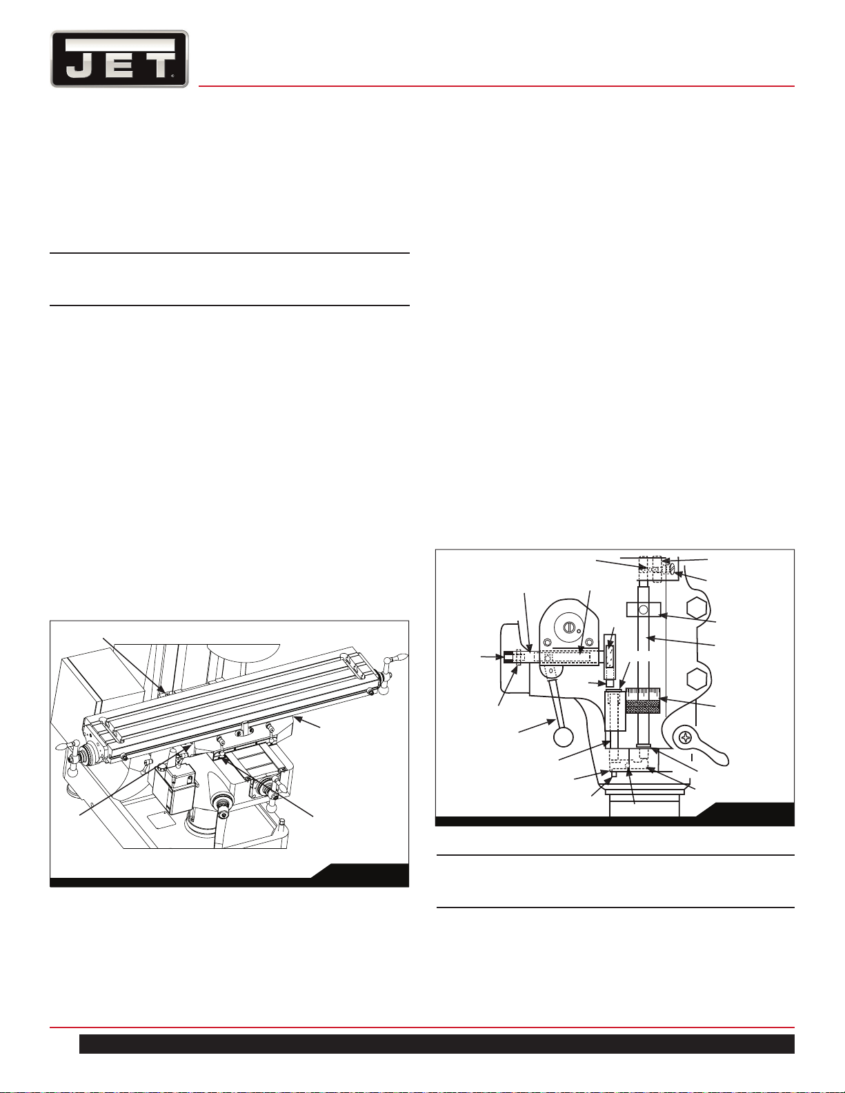
10.6 TABLE LEAD SCREW BACKLASH
ADJUSTMENT
Refer to Figure 24.
The milling machine table is moved by a lead screw and
nut for each machine axis. For proper operation, there
must be clearance between the lead screw and the nut,
which results in backlash. A second lead screw nut is
provided to eliminate most of the backlash. The following
procedures provide instructions for obtaining acceptable
backlash.
Cross Feed Backlash Adjustment:
1. Use the cross feed crank to move the table to the
extreme rear of its travel.
2. Remove the pleated way cover.
3. Open the two chip guards enough to expose the
cross-feed adjustment nut (the nut that is toward the
rear of the nut bracket is not adjustable – only the front
nut is adjustable).
4. Loosen the two nut locking screws.
5. Turn the nut slightly to tighten it against the opposing
nut.
6. Tighten the two nut locking screws.
7. Using the cross-feed crank, move the table to the
middle position.
8. Set up a dial indicator to check cross-feed backlash.
Gently move the cross feed crank back and forth while
watching the dial indicator. Backlash should be be-
tween 0.003 inch and 0.005 inch.
9. If necessary, repeat the steps above to set backlash.
10. Install the pleated way cover.
Longitudinal Backlash Adjustment:
Refer to Figure 24.
1. Only one of the longitudinal lead screw nuts can be
adjusted. The other nut is fixed. The left hand nut is
typically adjustable. This can be determined by
looking at the nut from the underside of the table.
2. Loosen the two nut locking screws.
3. Turn the nut slightly to tighten it against the opposing
nut.
4. Tighten the two nut locking screws.
5. Using the longitudinal table crank, move the table to
the middle position.
6. Set up a dial indicator to check longitudinal backlash.
Gently move the crank back and forth while watching
the dial indicator. The backlash should be between
0.003 inch and 0.005 inch.
If necessary, repeat the steps above to set backlash.
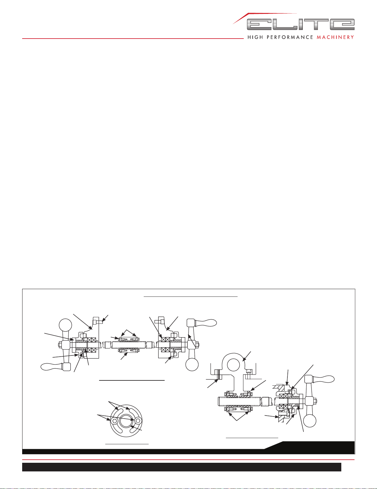
Fig. 24
Table Lead Screw Components
Feed nut - end view
Cross-feed section view
Longitudinal feed section view
Slots allow adjustment
of thread tightness
Lock Screws
Threads in bore
accept lead screw
Leadscrew nut set
Knee
Casting
Graduated dial
Dial holder
Bearing retainer ring
Bearing
Bracket
Adjustable
nut
Rollpin
Sealed ball
bearings
Right bearing bracket
Bearing
retaining ring
Bearing bracket
cap screws
Longitudinal
lead screw nut set
Adjustable
nut
Left bearing bracket
Dial
lock
ring
Graduated
dial
Shim(s)
Dial holder
Nut bracket
(same part as cross-feed
section view)
Nut bracket
(same part as longitudinal
feed section view)
22
MILL
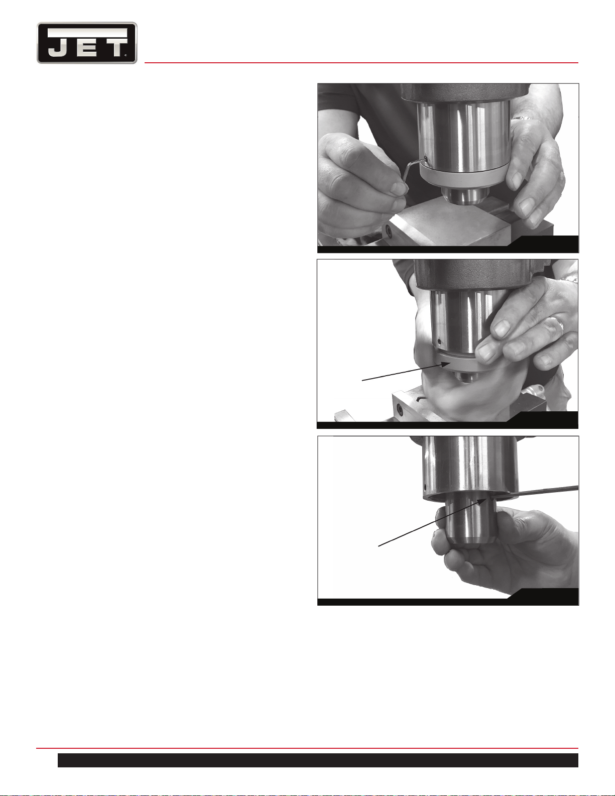
10.7 SPINDLE PIN (COLLET RETENTION)
A spindle pin (set screw) protrudes into the interior of the
spindle to prevent a collet from rotating inside the spindle.
It has been set by the manufacturer to protrude 1.6mm be-
yond the interior spindle wall. However, collets may have
varied groove depths. If this pin needs adjustment:
1. Remove set screw at rear of quill with 2.5mm hex
key. See Figure 25.
2. Unscrew end cap from quill. (NOTE: Left hand
thread – clockwise to remove). See Figure 26.
3. Adjust spindle pin to desired depth with 3mm hex key.
See Figure 27.
4. Insert collet to confirm the fit.
5. When satisfied, reinstall end cap and rear set screw.
Fig. 25
Fig. 26
Fig. 27
23
ETM–949 | ETM–949EVS
Fig. 29
11.0 MAINTENANCE
11.1 LUBRICATION
The milling machine is equipped with a “auto lube” lu-
brication system. The system lubricates the lead screws
and ways. An oil cup and grease nipple on the mill head
provide lubrication for the spindle bearings and back gear
mechanism. Refer to Figures 28 and 29 for lubrication
requirements and access points.
Key Description Recommended
Lubricant
Action
A
Spindle bearing
oil cup
Mobil DTE Oil
Light, or equiv-
alent
Service daily.
B
Auto Lube Mobil Vactra Oil
#2, or equiva-
lent
Check oil daily –
add if required.
Pull lube handle
every hour
during opera-
tions.
C
Knee leadscrew
grease nipple
Mobilith AW2, or
equivalent
Service once
each week.
D
Back gear
grease nipple
Mobilith AW1, or
equivalent
Service weekly
when operating
in back gear
mode.
Before any intervention on the machine, disconnect
it from the electrical supply by pulling out the plug
or switching off the main switch! Failure to comply
may cause serious injury.
!
Table 2
11.2 PERIODIC MAINTENANCE REQUIREMENTS
During operation, periodically vacuum and brush chips
and debris from machine.
Periodically operate knee and table lead screws through
full range of movement to evenly distribute lubricant.
Periodically apply light machine oil to work table and other
exposed metal surfaces to prevent rust or corrosion.
Periodically remove vent panels to check pulleys and belts
for unusual wear or grooving.
NOTE: Operators should vary speed occasionally to
prevent formation of grooves on the pulley surfaces.
Fig. 28
A
D
C
B

24
MILL
12.0 RECOMMENDED SPEED FOR
MILL AND DRILL OPERATION
Mill cutting speed recommended (mm/min)
V=DN/ 1000
V cutting speed (m/ min)
Material Heavy
Cutting
Processing
Cutting
Cast iron 30-40 45-90
Malloable iron 37-45 45-90
Steel (Soft) 60-90 75-105
Steel (Medium) 454-67 52-75
Steel (Hard) 24-37 55-75
Cast Steel 24-30 55-75
Alluminum 240-300 300-360
Brass 105-180 150-300
Bronze 52-75 75-90
Magnesium Alloy 240-300 300-600
Zinc Alloy 120-240 210-450
Drill speed (RPM) recommend
5mm hole 1000-1500
10mm hole 500-800
13mm 300-500
20mm 150-300
13.0 REPLACEMENT PARTS —
ETM-949, ETM–949EVS
Replacement parts are listed on the following pages. To
order parts or reach our service department, call 1-800-
274-6848 Monday through Friday, 8:00 a.m. to 5:00 p.m.
CST. Having the Model Number and Serial Number of
your machine available when you call will allow us to serve
you quickly and accurately.
Non-proprietary parts, such as fasteners, can be found at
local hardware stores, or may be ordered from JET.
Some parts are shown for reference only, and may not be
available individually.
JET
®
427 New Sanford Road
LaVergne, Tennessee 37086
www.jettools.com
Phone: 855-336-4032
25
ETM–949 | ETM–949EVS
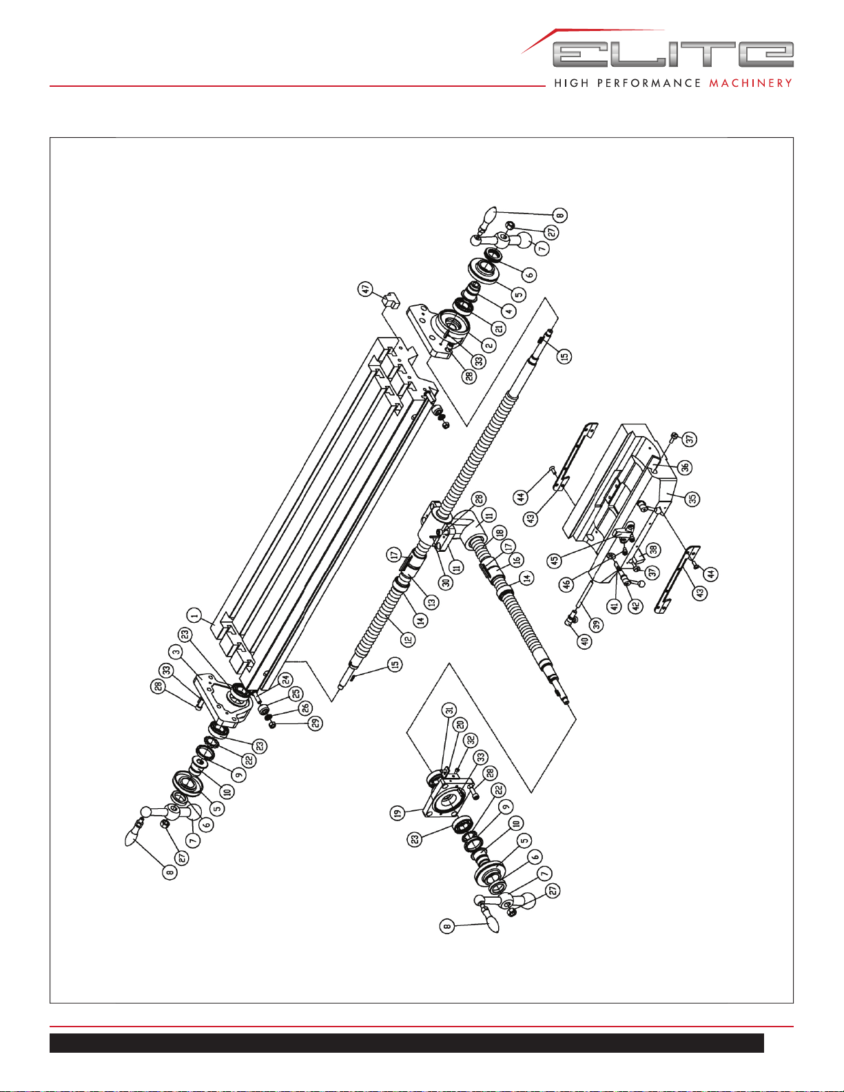
TABLE ASSEMBLY — ETM–949, ETM–949EVS

26
MILL
TABLE ASSEMBLY PARTS LIST
Index No. Part No. Description Size Qty.
1 ETM949-A01 Table 9”×49” 1
2 ETM949-A02 Left Bearing Bracket 1
3 ETM949-A03 Right Bearing Bracket 1
4 ETM949-A04 Dial Holder 1
5 ETM949-A05 Inch Dial inch 3
6 ETM949-A06 Dial Nut 1
7 ETM949-A07 Ball Crank Handle 3
8 ETM949-A08 Ball Crank Handle Lever 3/8”-16UNC 3
9 ETM949-A09 Lock Nut 2
10 ETM949-A10 Dial Holder 2
11 ETM949-A11 Feed Nut Bracket 1
12 ETM949-A12 Longitudinal Feed Screw 49” 1
13 ETM949-A13 Longitudinal Feed Nut (inch) 2
14 ETM949-A14 Backlash Adjustment Nut inch 2
15 ETM949-A15 Flat Key 3×3×20 3
16 ETM949-A16 Cross Feed Screw Nut (inch) 2
17 ETM949-A17 Flat Key 5×5×50 2
18 ETM949-A18 Cross Feed Screw (inch) 1
19 ETM949-A19 Cross Feed Bearing Bracket 1
20 ETM949-A20 Front Rubber Chip Cover Shaft Bracket 2
21 BB-6204 Bearing 6204 1
22 ETM949-A22 Lock Washer AW04 2
23 BB-51105 Bearing 51105 4
24 ETM949-A24 Stop Piece T-Bolt 2
25 ETM949-A25 Table Stop Piece 2
26 ETM949-A26 Washer 2
27 TS-0561031 Nut 3/8” 3
28 ETM949-A28 Bolt 3/8”×1” 16
29 TS-0561031 Nut 3/8” 2
30 ETM949-A30 Overload Clutch Lever Spring Plunger 5x30 2
31 ETM949-A31 Cross-Recessed Head Screw 3/16”× 5/8” 2
32 TS-1502021 Bolt M5×10 2
33 ETM949-A33 Overload Clutch Lever Spring Plunger 6×25 6
35 ETM949-A35 Saddle 49” 1
36 ETM949-A36 Saddle Knee Gib 1
37 ETM949-A37 Adjusting Screw 3
38 ETM949-A38 Saddle Table Gib 1
39 ETM949-A39 Saddle Lock Plunger 1
40 ETM949-A40 Table Lock Bolt Handle 1/2”-12UNC 1
41 ETM949-A41 Adaptor Pivot Stud Locknut 1
42 ETM949-A42 Table Lock Bolt Handle 1/2”-12UNC 2
43 ETM949-A43 Felt Wipers 1
44 ETM949-A44 Cross-Recessed Head Screw 3/16 ×15 8
45 ETM949-A45 Table Stop Bracket 1
46 TS-0209051 Hex-Socket Head Cap Screw 3-8×15 2
27
ETM–949 | ETM–949EVS
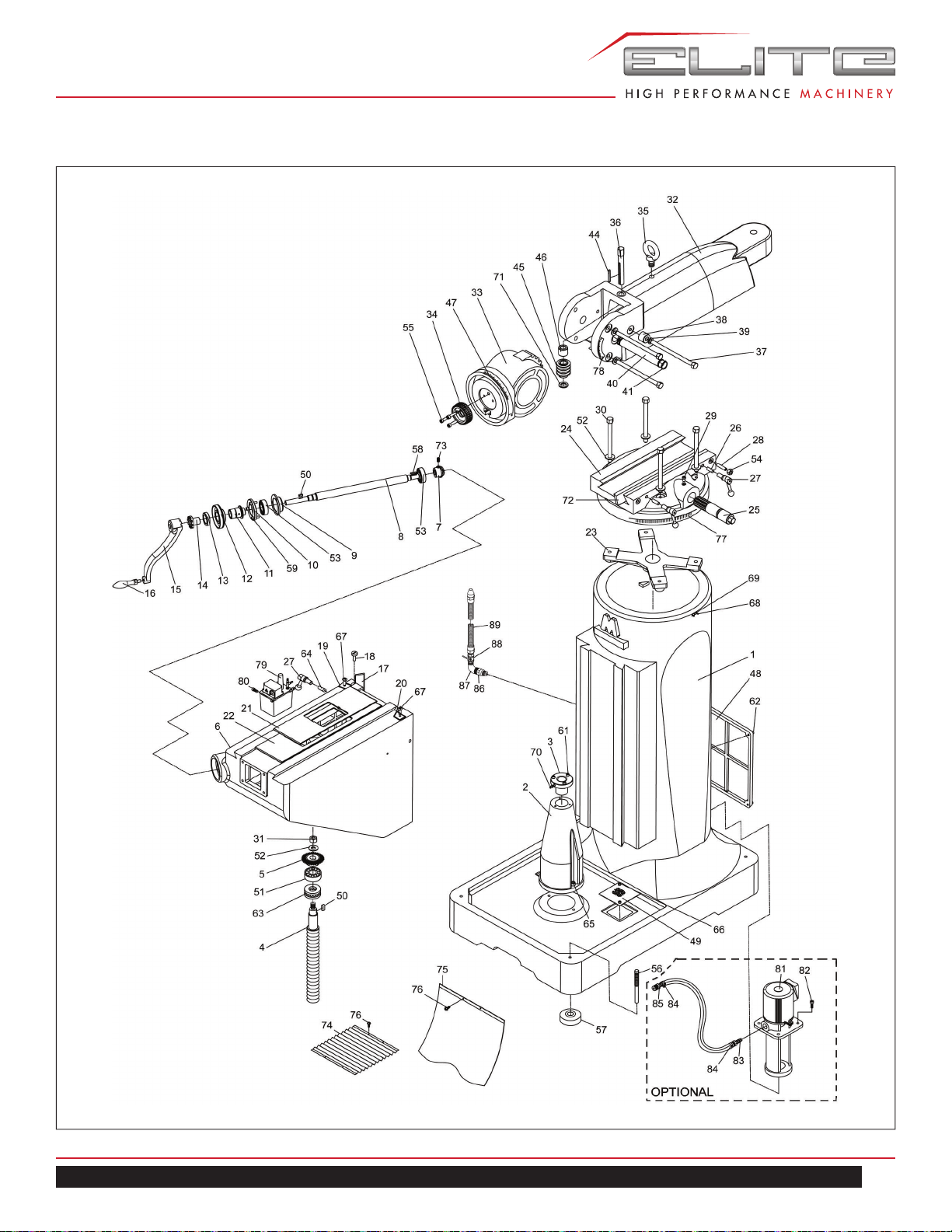
BASE ASSEMBLY — ETM–949, ETM–949EVS

28
MILL
BASE ASSEMBLY PARTS LIST
Index No. Part No. Description Size Qty.
1 ETM949-B01 Body 1
2 ETM949-B02 Elevating Screw Housing 1
3 ETM949-B03 Elevating Screw Nut(Inch) 1
4 ETM949-B04 Elevating Screw (Inch) 1
5 ETM949-B05 Bevel Gear (Big) 1
6 ETM949-B06 Knee 1
7 ETM949-B07 Bevel Gear(Small) 1
8 ETM949-B08 Elevating Shaft 1
9 ETM949-B09 Bearing Housing 1
10 ETM949-B10 Bearing Cap 1
11 ETM949-B11 Dial Holder 1
12 ETM949-B12 Inch Dial 1
13 ETM949-B13 Dial Nut 1
14 ETM949-B14 Gear Shaft Clutch Insert 1
15 ETM949-B15 Elevating Crank 1
16 ETM949-B16 Ball Crank Handle Lever 3/8”-16UNC 1
17 ETM949-B17 Knee Column Gib 1
18 ETM949-B18 Adjusting Screw 2
19 ETM949-B19 Felt Wipers 1
20 ETM949-B20 Felt Wipers 1
21 ETM949-B21 Chip Guards (Down) 1
22 ETM949-B22 Chip Guards (Up) 1
23 ETM949-B23 Spider 1
24 ETM949-B24 Turret 1
25 ETM949-B25 Ram Pinion 1
26 ETM949-B26 Ram Lock Plunger 2
27 ETM949-B27 Table Lock Bolt Handle
(Include C038) 1/2”-12UNC
3
28 ETM949-B28 Gib Lock Screw 1
29 ETM949-B29 Ram Pinion Set 1
30 ETM949-B30 Locking Bolt 4
31 TS-0561051 Nut 1/2” 1
32 ETM949-B32 Ram 1
33 ETM949-B33 Ram Adaptor 1
34 ETM949-B34 Quill Housing Adjusting Gear 1
35 ETM949-B35 Hook 1
36 ETM949-B36 Vertical Adjusting Worm Shaft 1
37 ETM949-B37 Adaptor Locking Bolt 185mm 3
38 ETM949-B38 Adaptor Pivot Stud Locknut 1
39 TS-155009 Washer M14 1
40 ETM949-B40 Adaptor Pivot Stud 1
41 ETM949-B41 Snap Ring C-Type S-26 2
42 TS-155009 Washer M14 1
43 TS-155009 Washer M14 1
44 ETM949-B44 Flat Key 5×5×50 1
45 ETM949-B45 Vertical Adjusting Worm 1

29
ETM–949 | ETM–949EVS
Index No. Part No. Description Size Qty.
46 ETM949-B46 Worm Thrust Washer 1
47 ETM949-B47 Adaptor Scale 1
48 ETM949-B48 Back Cover 2
49 ETM949-B49 Filter Oil Net 2
50 ETM949-B50 Flat Key 5×5×15 2
51 BB-6205 Bearing 6205 1
52 ETM949-B52 Washer 4
53 BB-6204 Bearing 6204 2
54 TS-0561031 Nut 3/8” 1
55 TS-1504051 Hex-Socket Head Cap Screw M8 × 25 3
56 ETM949-B56 Level Screw And Nut 4
57 ETM949-B57 Leveling Pads 4
58 ETM949-B58 Flat Key 4×4×20 1
59 TS-1503051 Hex-Socket Head Cap Screw M6 × 20 3
60 TS-1503051 Hex-Socket Head Cap Screw M6 × 20 1
61 TS-1503051 Hex-Socket Head Cap Screw M6 × 20 2
62 TS-1503041 Hex-Socket Head Cap Screw M6× 15 8
63 ETM949-B63 Bearing 51305 1
64 ETM949-B64 Knee Lock Plunger 1
65 TS-1505021 Hex-Socket Head Cap Screw M10 × 20 2
66 TS-1502021 Hex-Socket Head Cap Screw M5 × 10 4
67 TS-1503031 Cross-Recessed Head Screw M6 ×12 2
68 ETM949-B68 Rivet Nut M2×5 4
69 ETM949-B69 Zeroing Point Plate 1
70 ETM949-B70 Nozzle 1/8PT 1
71 ETM949-B71 Washer 1
72 ETM949-B72 Turret-Ram Gib 1
73 TS-1534032 Set Screw M6×10 1
74 ETM949-B74 Rubber Chip Cover ( Front, Wave) 1
75 ETM949-B75 Rubber Chip Cover ( Rear, Flat ) 1
76 TS-1534041 Cross-Recessed Head Screw M5×10 8
77 ETM949-B77 Turret Scale 1
78 ETM949-B78 Angle Plate 1
79 ETM949-B79 Auto Lubricator 1
80 TS-1534041 Cross-Recessed Head Screw M5×10 4
81 ETM949-B81 Coolant Pump 150L * RE: 894092 1
82 TS-1503051 Hex-Socket Head Cap Screw* M6× 20 4
83 ETM949-B83 Water Pipe Adapter* RE: 894092 3/8PT×3/8HS 1
84 ETM949-B84 Restraint* RE: 894092 5/8” 2
85 ETM949-B85 Water Pipe Adapter* RE: 894092 1/2PT×1/2HS 1
86 ETM949-B86 Insert Connect 3/8PT×7/8HS 1
87 ETM949-B87 High Pressure Connect L-Type 3/8PT×3/8PT 1
88 ETM949-B88 Switch 3/8” 1
89 ETM949-B89 Flexible Steel Coolant Hose 30” 1
* optional accessory - order 894092 Coolant System
30
MILL
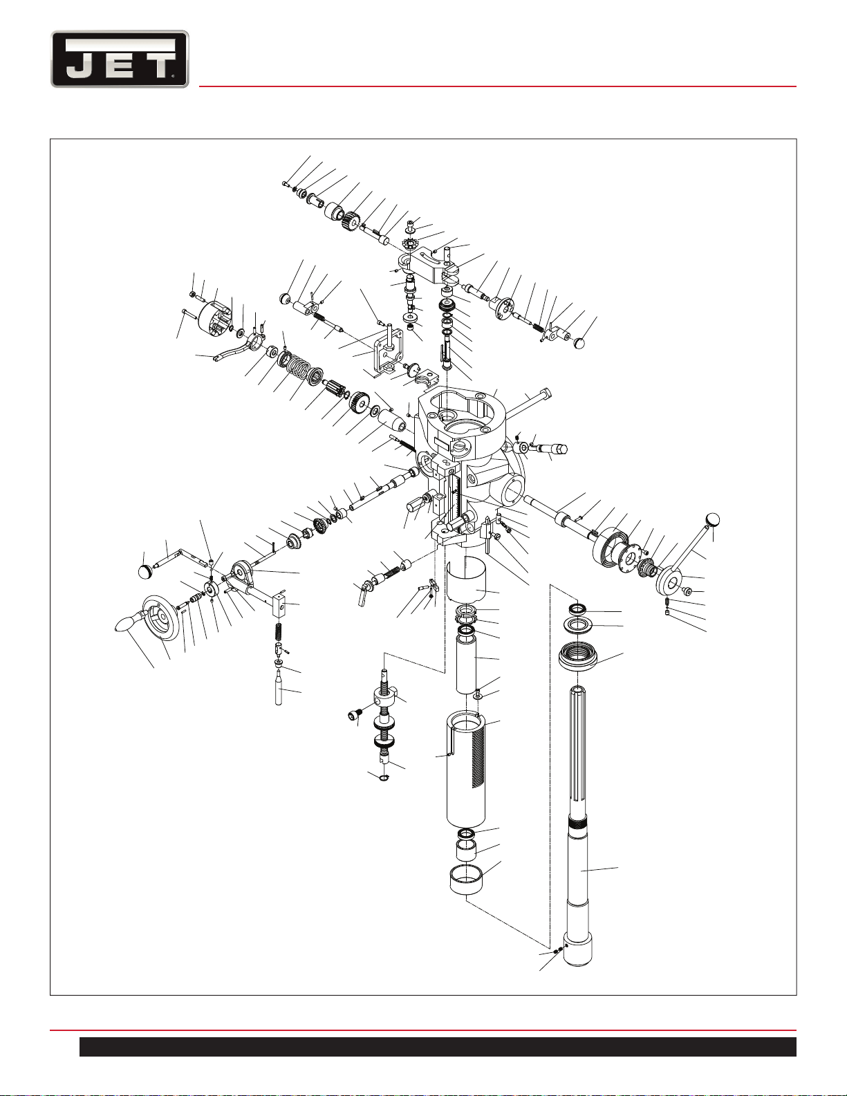
HEAD ASSEMBLY — ETM–949, ETM–949EVS
29
30
40
50
70
80
60
90
20
10
106
105
104
103
102
101
100
22
99
113
112
111
116
117
107
118
119
106
120
121
123
124
122
74
115
100
108
110
109
114
98
97
95
94
93
92
96
1
150
52
51
50
49
48
46
47
43
121
120
128
125
129
116
126
127
116
133
131
132
130
53
45
44
42
41
40
39
38
37
36
35
159
155
156
54
56
57
55
116
59
60
61
62
61
63
64
79
73
74
78
81
58
65
67
85
84
86
83
82
80
77
75
66
76
87
151
152
153
148
139
140
141
142
88
90
91
87
134
135
15
136
95
7
9
8
157
158
2
14
17
18
10
11
12
13
19
5
6
7
146
147
145
144
143
149
31
29
30
34
27
32
33
28
26
25
24
23
22
21
20
74
122
124
123
53

31
ETM–949 | ETM–949EVS
HEAD ASSEMBLY PARTS LIST
Index No. Part No. Description Size Qty.
1 ETM949-C01 Milling Head 1
2 ETM949-C02 Spindle R8 1
3 ETM949-C03 Stop Block 2
4 TS-0208031 Hex Socket Head Cap Screw 5/16”x5/8” 2
5 ETM949-C05 Nut R8 1
6 ETM949-C06 Spindle Dirt Shield 1
7 BB-7207 Bearing 7207 2
8A ETM949-C08A Bearing Spacer Assembly (Includes #8,9) 1
8 ETM949-C08 Bearing spacer (large) 1
9 ETM949-C09 Bearing spacer (large) 1
10 ETM949-C10 Sleeve 1
11 BB-6206 Bearing 6206 1
12 ETM949-C12 Lock Washer AW-06 1
13 ETM949-C13 Locknut Washer (M30) 1
14 ETM949-C14 Quill 1
15 ETM949-C15 Set Screw M5×5 2
17 TS-1550031 Washer M5 1
18 TS-1502021 Hex Socket Head Cap Screw M5×10 2
19 ETM949-C19 Quill Skirt 1
20A ETM949-C20A Quill Pinion Shaft Assembly (Includes #20,21) 1
20 ETM949-C20 Quill Pinion Shaft 1
21 ETM949-C21 Pin 1
22 ETM949-C22 Flat Key 3×3×18 1
23 ETM949-C23 Clock Spring 1
24 ETM949-C24 Spring Cover 1
25 TS-1502031 Hex Socket Head Cap Screw M5×12 2
26 ETM949-C26 Pinion Shaft Hub Sleeve 1
27 ETM949-C27 Back Feed Handle Hub (Quill Feed Lever) 1
28 ETM949-C28 Overload Clutch Lever Spring Plunger Ø5×16” 1
29 ETM949-C29 Steel Ball 3/16” 2
30 ETM949-C30 Compression Spring 1
31 TS-0270031 Set Screw 5/16”×3/8” 1
32 ETM949-C32 Pinion Shaft Hub Handle 1
33 ETM949-C33 Black Plastic Ball 3/8” 1
34 ETM949-C34 Pinion Shaft Hub Screw 1
35 ETM949-C35 Quill Pinion Shaft Bushing 1
36 ETM949-C36 Quill Pinion Shaft Worm Gear Spacer 1
37 ETM949-C37 Overload Clutch Worm Gear 1
38 ETM949-C38 Snap Ring C-Type S-15 1
39A ETM949-C39A Overload Clutch Assembly (Includes
#39,40,42)
1
39 ETM949-C39 Over Load Clutch 1
40 ETM949-C40 Overload Clutch 1
41 ETM949-C41 Safety Clutch Spring 1
42 ETM949-C42 Overload Clutch Locknut 1

32
MILL
Index No. Part No. Description Size Qty.
43 ETM949-C43 Set Screw M5×5 1
44 ETM949-C44 Clutch Ring 1
45 ETM949-C45 Overload Clutch Trip Lever 1
46 ETM949-C46 Clutch Ring Pin 2
47 ETM949-C47 Overload Clutch Lever Spring Plunger Ø5×18 1
48 ETM949-C48 Overload Clutch Washer 1
49 ETM949-C49 Snap Ring C-Type S-10 1
50 ETM949-C50 Clutch Arm Cover 1
51 TS-0267071 Set Screw 1/4”×3/4” 1
52 TS-0561011 Nut 1/4” 1
53 TS-1502081 Hex Socket Head Cap Screw M5×35 2
54 ETM949-C54 Bushing 1
55 ETM949-C55 Feed Worm Shaft 1
56 ETM949-C56 Flat Key 3×3×15 1
57 ETM949-C57 Flat Key 3×3×10 1
58 ETM949-C58 Feed Worm Shaft Bushing 1
59 ETM949-C59 Feed Worm Shaft Thrust Washer 1
60 ETM949-C60 Snap Ring C-Type S-12 1
61 ETM949-C61 Feed Reverse Bevel Gear 2
62 ETM949-C62 Feed Reverse Clutch 1
63 ETM949-C63 Overload Clutch Lever Spring Plunger Ø3×20 1
64 ETM949-C64 Reverse Clutch Rod 1
65 ETM949-C65 Feed Trip Bracket 1
66 TS-1503051 Hex Socket Head Cap Screw M6×20 2
67 ETM949-C67 Cam Rod Sleeve Assembly 1
73 ETM949-C73 Trip Handle 1
74 ETM949-C74 Black Plastic Ball 1/4” Dia 1/4” 3
75 ETM949-C75 Overload Clutch Lever Spring Plunger Ø5×20 1
76 ETM949-C76 Trip Plunger Bushing 1
77 ETM949-C77 Hand wheel Clutch 1
78 ETM949-C78 Compression Spring 1
79 ETM949-C79 Hand wheel Clutch Spring Screw 1
80 TS-0267021 Set Screw 1/4”×1/4” 1
81A ETM949-C81A Feed Reverse Knob Assembly
(Includes #81,82,83)
1
81 ETM949-C81 Snap Ring E-Type E5 1
82 ETM949-C82 Feed Reverse Knob Stud 1
83 ETM949-C83 Feed Reverse Knob Stud Bolt 1
84A ETM949-C84A Hand wheel & Hand wheel Handle Assembly
(#84,85)
1
84 ETM949-C84 Hand wheel & Hand wheel Handle 1
85 ETM949-C85 Handle M8 P1.25 1
86 ETM949-C86 Overload Clutch Lever Spring Plunger Ø3×16 1
87 ETM949-C87 Feed Trip Plunger 1
88 ETM949-C88 Trip Lever Pin 1
89 ETM949-C89 Feed Trip Lever 1

33
ETM–949 | ETM–949EVS
Index No. Part No. Description Size Qty.
90 TS-1521071 Set Screw M4×20 1
91 TS-1540021 Nut M4 1
92 ETM949-C92 Cluster Gear Shaft 1
93 ETM949-C93 Bevel Gear Thrust Spacer 1
94 ETM949-C94 Bevel Gear Bushing 1
95 ETM949-C95 Snap Ring C-Type S-16 2
96 ETM949-C96 Flat Key 3×3×45 1
97 ETM949-C97 Cluster Gear 1
98 ETM949-C98 Cluster Gear Shaft Upper Bushing 1
99 ETM949-C99 Feed Drive Worm Gear Shaft 1
100 ETM949-C100 Flat Key 3×3×x8 2
101 ETM949-C101 Feed Drive Worm Gear 1
102 ETM949-C102 Worm Cradle Bushing 1
103 ETM949-C103 Feed Worm Gear Shaft Sleeve 1
104 ETM949-C104 Feed Bevel Pinion 1
105 ETM949-C105 Washer 1
106 TS-1502031 Hex Socket Head Cap Screw M5×12 1
107 ETM949-C107 Worm Gear Cradle 1
108A ETM949-C108A Feed Driving Gear Assembly
(includes #108, 110)
1
108 ETM949-C108 Feed Driving Gear 1
109 ETM949-C109 Feed Drive Gear 1
110 ETM949-C110 Flat Key 3×3×10 1
111 ETM949-C111 Feed Reverse Bevel Gear 1
112 ETM949-C112 Washer 1
113 TS-1504031 Hex Socket Head Cap Screw M8×16 1
114 ETM949-C114 Bearing BA66 1
115 ETM949-C115 Set Screw M6x25 1
116 TS-1523011 Set Screw M6×6 3
117 ETM949-C117 Feed Engage Pin 1
118 ETM949-C118 Worm Gear Cradle Throw-Out 1
119 ETM949-C119 Shift Sleeve 1
120 ETM949-C120 Gear Shift Plunger 1
121 ETM949-C121 Compression Spring 1
122 ETM949-C122 Shift Crand 2
123 TS-0267021 Set Screw 1/4”×1/4” 2
124 ETM949-C124 Overload Clutch Lever Spring Plunger 3×20 2
125 ETM949-C125 Cluster Gear Cover 1
126 ETM949-C126 Cluster Gear Shift Crank 1
127 ETM949-C127 Feed Gear Shift Fork 1
128 ETM949-C128 Feed Shift Rod 1
129 ETM949-C129 Overload Clutch Lever Spring Plunger 3×18 1
130 ETM949-C130 Adj Worm Shaft 1
131 ETM949-C131 Flat Key 4×4×18 1
132 ETM949-C132 Warm Gear 1
133 ETM949-C133 Set Screw 1

34
MILL
Index No. Part No. Description Size Qty.
134 ETM949-C134 Quill Stop Knob 1
135 TS-0209021 Hex Socket Head Cap Screw 3/8”×5/8” 1
136 ETM949-C136 Quill Stop Micro-Screw (Meter) 1
139 ETM949-C139 Quill Lock Sleeve 1
140 ETM949-C140 Springs 2
141 ETM949-C141 Quill Lock Sleeve Tapped 1
142 ETM949-C142 Quill Lock Bolt & Spring 5/16”-18UNC 1
143 ETM949-C143 Feed Reverse Trip Plunger 1
144 ETM949-C144 Reverse Trip Ball Lever 1
145 ETM949-C145 Reverse Trip Ball Lever Screw 1
146 ETM949-C146 Indicator Rod 1
147 ETM949-C147 Indicator Rod Screw 1
148 ETM949-C148 Micrometer Scale(Inch) 1
149 ETM949-C149 Cross-Recessed Head Screw 1/8”×3/16” 1
150 ETM949-C150 Tee Bolt 1/2”-12 Nc 4
151 ETM949-C151 Lower Clamping Bolt Spacer 2
152 TS-0680061 Washer 1/2” 4
153 ETM949-C153 Adaptor Nut 1/2”-12nc 4
155 ETM949-C155 Hex-Socket Head Cap Screw M4x15 1
156 ETM949-C156 Compression Spring 1
157 ETM949-C157 Special Socket Set Screw 1
158 ETM949-C158 Set Screw M6×5 1
159 ETM949-C159 Overload Clutch Lever Spring Plunger 1
160 ETM949-C160 Draw bar w/washer (not shown) 1
ETM949-HA Complete Mill Head Assembly (logo, labels,
upper head, lower head parts) with Motor
ETM949-HAWOM Complete Mill Head Assembly (logo, labels,
upper head, lower head parts) without Motor
ETM949EVS-HA Complete Mill Head Assembly (logo, labels,
upper head, lower head parts) with Motor
ETM949EVS-
HAWOM
Complete Mill Head Assembly (logo, labels,
upper head, lower head parts) without Motor
35
ETM–949 | ETM–949EVS
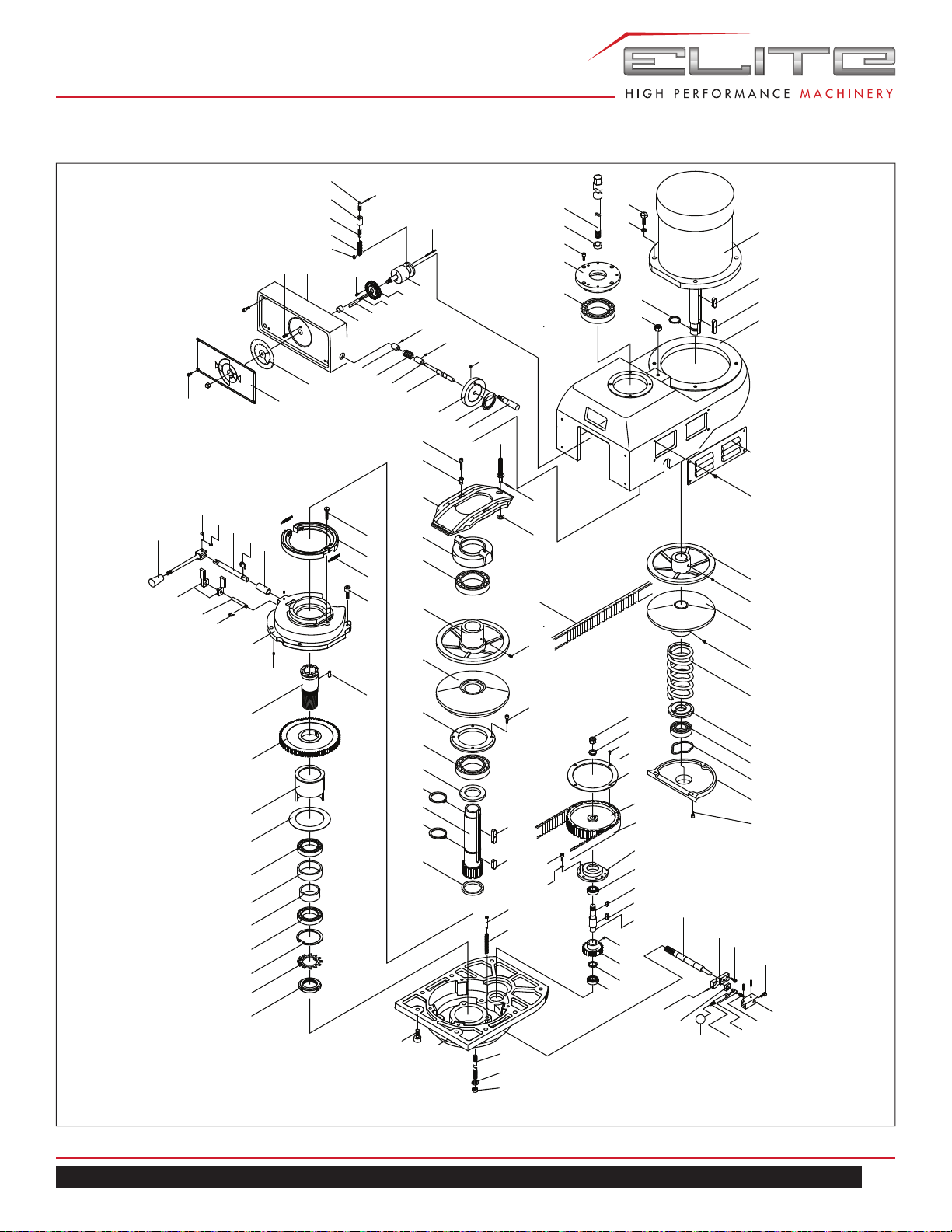
UPPER HEAD ASSEMBLY — ETM–949
MOTOR IS
R
UNNING
U
N
L
E
SS
D0
NAT
T
URN
CAUTION
SPINDLE
LO
60HZ 60-500
50H
Z 50-415
60HZ 500-4200
50HZ 410-3500
HI
SPEED
3300
500
340
2900
2600
260
300
120
100
1100
1300
1700
1500
140
1
8
0
700
900
60Hz
80
160
2100
1900
2300
200
230
430
420
390
500
440
3650
3450
3800
60
18
19
20
21
22
30
29
28
17
25
16
23
24
25
26
27
35
35
41
34
33
32
31
36
37
38
39
42
43
44
40
47
45
46
49
50
52
65
66
67
68
67
75
74
73
72
71
70
69
41
76
77
78
79
41
82
81
83
84
85
86
87
88
86
89
90
91
135
117
132
133
134
131
130
129
128
127
126
125
124
123
122
120
111
116
115
51
119
118
114
113
112
111
108
121
110
109
64
62
02
63
106
11
102
101
100
99
103
104
105
94
61
60
59
58
50
57
56
55
54
53
98
54
97
96
95
48
17
93
92
08
07
04
03
02
01
13
12
11
10
09
05
06

36
MILL
UPPER HEAD ASSEMBLY PARTS LIST
Index No. Part No. Description Size Qty.
1 ETM949-D01 Motor 1
ETM949-D01A Motor With Pulley Assembly (includes #
1,2,3,7,54,95-99)
1
2 ETM949-D02 Key 10×8×10 2
3 ETM949-D03 Key 1
4 ETM949-D04 Upper Pulley Box 1
5 TS-0209051 Screw 3/8”×1” 2
6 TS-0733061 Spring Washer 3/8” 4
7 ETM949-D07 Snap Ring C-Type S-30 2
8 TS-0561031 Nut 3/8” 1
ETM949-D09A Draw Bar w/ Nut Assembly( included # 9-10) 7/16”-20UNF1
9 ETM949-D09 Draw Bar Nst#30 1/2” 12unf 1
10 ETM949-D10 Washer (NT#30) S45C/cm 1
11 TS-1503051 Hex Socket Head Cap Screw M6×20 4
12 ETM949-D12 Top Bearing Bracket 1
13 BB-6007 Ball Bearing 6007 1
16 ETM949-D16 Hi-Low Detent Plunger Ø3×40 1
17 ETM949-D17 Hi-Low Detent Plunger Ø4×20 1
18 ETM949-D18 Speed Change Chain Stud 1
19 ETM949-D19 Speed Change Chain Stud 1
20 ETM949-D20 Speed Change Chain Stud 1
21 ETM949-D21 Chain #35-8P 1
22 ETM949-D22 Chain Washer 1
23 ETM949-D23 Speed Change Chain Drum 1
24 ETM949-D24 Feed Drive Worm Gear 1
25 ETM949-D25 Hi-Low Detent Plunger Ø5×10 2
26 ETM949-D26 Hi-Low Detent Plunger Ø5×30 1
27 ETM949-D27 Bushing 1
28 ETM949-D28 Speed Change Housing 1
29 ETM949-D29 Lock Screw 1
30 TS-1503081 Hex Socket Head Cap Screw M6×35 4
31 ETM949-D31 Vari Speed Dial 60 Hz 1
32 ETM949-D32 Speed Ind. Plate 1
33 TS-0561021 Nut 5/16” 1
34 ETM949-D34 Type III Phillips Screws M4×6 4
35 TS-1522011 Set Screw M5×6 3
36 ETM949-D36 Compression Spring 1
37 ETM949-D37 Worm 1
38 ETM949-D38 Worm Cradle Bushing 1
39 ETM949-D39 Speed Control Shaft 1
40 TS-1502051 Hex Socket Head Cap Screw M5×20 2
41 TS-1523011 Set Screw M6×6 3
42 ETM949-D42 Handle 1
43 ETM949-D43 Speed Change Warring Plate 1
44 ETM949-D44 Handle 5/16”-18UNC 1
45 ETM949-D45 Pivot Sleeve 2
46 ETM949-D46 Speed Change Plate 1

37
ETM–949 | ETM–949EVS
Index No. Part No. Description Size Qty.
47 ETM949-D47 Speed Change Plate Pivot Stud 1
48 ETM949-D48 Clutch Washer 10.2×21×1.2 1
49 ETM949-D49 Sliding Housing 1
50 BB-6010 Ball Bearing 6010 2
51 ETM949-D51 Set Screw M8×6 1
52 ETM949-D52 Adj. Driven Vari-Disc Assembly 1
53 ETM949-D53 Belt 38X890 1
54 TS-2245081 Screw M5×8 2
55 ETM949-D55 Stationary Driven Vari-Disc 1
56 TS-1503051 Hex Socket Head Cap Screw M6×20 4
57 ETM949-D57 Brake Brg. Cap 1
58 ETM949-D58 Spindle Pulley Spacer 1
59 ETM949-D59 Snap Ring C-Type S-35 1
60 ETM949-D60 Spindle Clutch Device 1
61 ETM949-D61 Snap Ring C-Type S-40 1
62 ETM949-D62 Sliding Key 1
63 ETM949-D63 Timing Belt 225l 1
64 ETM949-D64 Timing Pulley Clutch Sleeve 1
65 ETM949-D65 Brake Ring Screw 1
66 ETM949-D66 Brake Shoe 1
67 ETM949-D67 Brake Spring 2
68 TS-1504041 Hex Socket Head Cap Screw M8×20 3
69 ETM949-D69 Sleeve For Brake 1
70 ETM949-D70 Snap Ring C-Type S-12 1
71 ETM949-D71 Brake Lock Shaft 1
72 ETM949-D72 Snap Ring E-Type E-4 1
73 ETM949-D73 Brake Lock Pin, S45C 1
74 ETM949-D74 Brake Lock & Handle 1
75 ETM949-D75 Black Plastic Ball Handle 5/16”-18UNC 1
76 ETM949-D76 Brake Finger Pivot Stud 2
77 ETM949-D77 Brake Operation Finger 1
78 ETM949-D78 Snap Ring E-Type E-6 1
79 ETM949-D79 Brake Base 1
81 ETM949-D81 Key 8×12 1
82 ETM949-D82 Spindle Pulley Hub 1
83 ETM949-D83 Spindle Bull Gear Assembly 1
84 ETM949-D84 Bull Gear Bearing Sleeve 1
85 ETM949-D85 Bull Gear Bearing Sleeve Washer 1
86 BB-6908 Ball Bearing 6908 2
87A ETM949-D87A Bull Gear Bearing Spacer Assembly
(includes #87,88)
1
87 ETM949-D87 Bull Gear Bearing Spacer 1
88 ETM949-D88 Bull Gear Bearing Spacer 1
89 ETM949-D89 Snap Ring C-Type R-62 1
90 ETM949-D90 Spacer AW08 1
91 ETM949-D91 Bearing Lock Nut 1
92 ETM949-D92 Side Belt Housing Cover 2

38
MILL
Index No. Part No. Description Size Qty.
93 ETM949-D93 Cross-Recessed Head Screw M6×8 8
94 ETM949-D94 Timing Belt Pulley Flange 1
95 ETM949-D95 Stationary Motor Vari-Disc 1
96 TS-1523021 Set Screw M6×8 1
97 ETM949-D97 Adj.Motor Vari-Disc 1
98 ETM949-D98 Spring 1
99 ETM949-D99 Spring Washer 1
100 BB-6204 Ball Bearing 6204 1
101 ETM949-D101 Washer 6204 1
102 ETM949-D102 Motor Pulley Cover 1
103 TS-0561071 Nut 5/8” 1
104 TS-0680081 Washer 5/8” 1
105 ETM949-D105 Countersunk Screws M5×8 4
106 ETM949-D106 Pullet Set 1
108 ETM949-D108 Cover 1
109 TS-1502041 Hex Socket Head Cap Screw M5×16 3
110 TS-1550031 Washer M5 3
111 BB-6203 Ball Bearing 6203 2
112 ETM949-D112 Key 5×15 1
113 ETM949-D113 Key 5×18 1
114 ETM949-D114 Bull Gear Pinion Counter Shaft 1
115 ETM949-D115 Bull Gear Pinion Counter Gear 1
116 ETM949-D116 Spacer 1
117 ETM949-D117 Gear Housing 1
118 ETM949-D118 Spring Supported Pin 3
119 ETM949-D119 Spring 3
120 ETM949-D120 Bull Gear Shifter Pinion Shaft 1
121 ETM949-D121 Hi-Low Detent Plate 1
122 TS-1502031 Hex Socket Head Cap Screw M5×12 2
123 ETM949-D123 Hi-Low Detent Plunger Ø3×20 2
124 TS-1503031 Hex Socket Head Cap Screw M6×16 1
125 TS-1521051 Set Screw M4×16 1
126 ETM949-D126 Adj. Plate 1
127 ETM949-D127 Black Plastic Ball 1/4” Dia 1/4”-20UNC 1
128 ETM949-D128 Hi-Low Shift Crank 1
129 ETM949-D129 Hi-Low Detent Plunger 1
130 ETM949-D130 Spring 1
131 ETM949-D131 Hi-Low Pinion Block 1
132 ETM949-D132 Studs 3
133 ETM949-D133 Washer 3
134 TS-0561041 Nut 7/16” 3
135 TS-1504051 Hex Socket Head Cap Screw M8x25 6
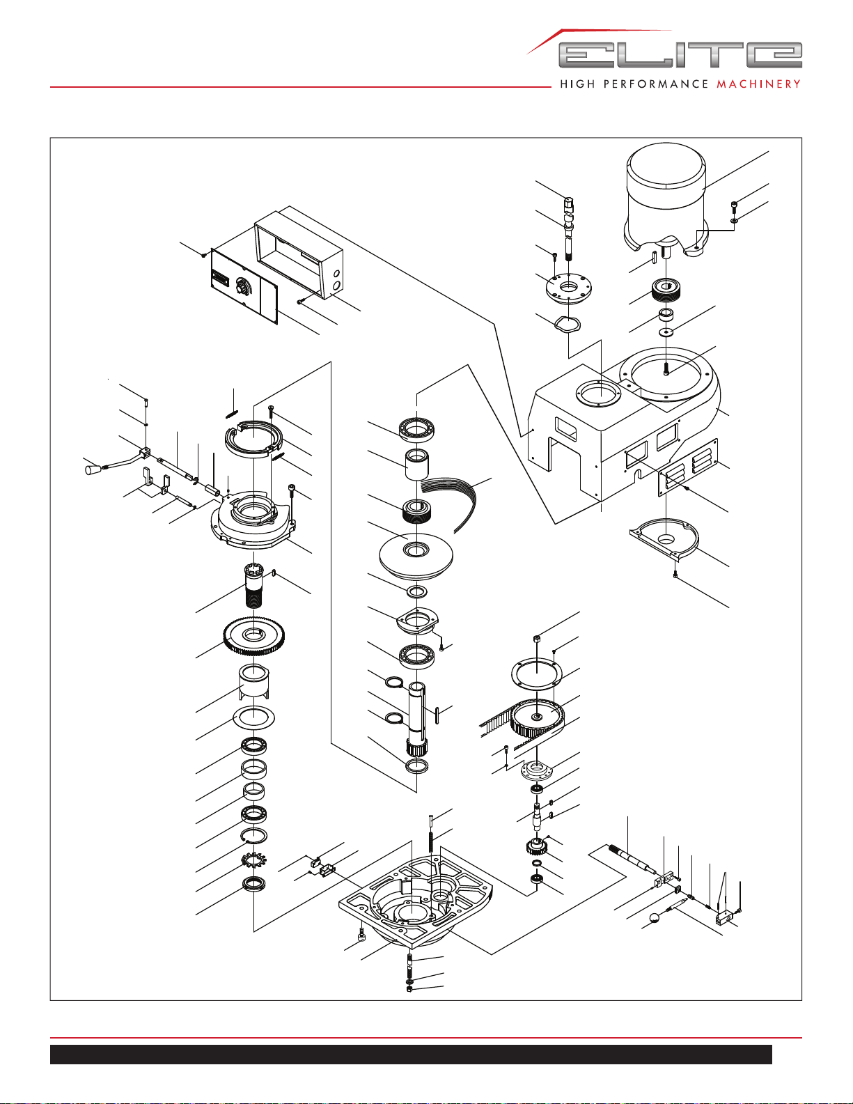
39
ETM–949 | ETM–949EVS
UPPER HEAD ASSEMBLY — ETM–949EVS
.M.CONTROL
5
103
100
101
102
36
35
37
26
34
33
32
29
28
27
26
25
38
39
40
41
23
21
20
19
18
15
17
22
16
15
14
13
12
11
9
10
8
5
4
1
2
3
6
7
79
76
75
74
73
81
80
78
77
72
71
70
56
57
58
59
60
61
62
56
63
64
65
67
66
104
68
69
96
42
55
43
44
45
46
48
47
49
50
51
53
54
52
95
99
98
97
94
93
92
91
90
86
85
84
83
82
89
88
87

40
MILL
UPPER HEAD ASSEMBLY PARTS LIST
Index No. Part No. Description Size Qty.
1 TS-0561041 Nut 7/16” 3
2 ETM949-D133 Washer 3
3 ETM949-D132 Studs 3
4 ETM949-D117 Gear Housing 1
5 TS-1504051 Hex Socket Head Cap Screw M8×25 6
6 ETM949-D118 Spring Supported Pin 3
7 ETM949-D119 Spring 3
8 ETM949EVS-D08 Limit Switch 1
9 TS-1501031 Hex Socket Head Cap Screw M4×10 2
10 ETM949EVS-D10 Limit Switch D2VW-5L2A-1M 1
11 TS-1540011 Nut M3×8 2
12 ETM949-D91 Bearing Lock Nut 1
13 ETM949-D90 Spacer AW08 1
14 ETM949-D89 Snap Ring C-Type R-62 1
15 BB-6908 Ball Bearing 6908 2
16 ETM949-D88 Bull Gear Bearing Spacer 1
17 ETM949-D87 Bull Gear Bearing Spacer 1
18 ETM949-D85 Bull Gear Bearing Sleeve Washer 1
19 ETM949-D84 Bull Gear Bearing Sleeve 1
20 ETM949-D83 Spindle Bull Gear Assembly 1
21 ETM949-D82 Spindle Pulley Hub 1
22 ETM949EVS-D22 Key 8×12 1
23 ETM949-D79 Brake Base 1
25 TS-1504041 Hex Socket Head Cap Screw M8×20 4
26 ETM949-D67 Brake Spring 2
27 ETM949-D66 Brake Shoe 1
28 ETM949EVS-D28 Brake Ring Screw 1/4”-20UNC 1
29 TS-1523011 Set Screw M6×6 1
32 ETM949-D69 Sleeve For Brake 1
33 ETM949-D70 Snap Ring C-Type S-12 1
34 ETM949-D71 Brake Lock Shaft 1
35 ETM949-D72 Snap Ring E-Type E-4 1
36 ETM949-D73 Brake Lock Pin S45C 1
37 ETM949-D74 Brake Lock & Handle 1
38 ETM949-D75 Black Plastic Ball Handle 5/16”-18UNC 1
39 ETM949-D76 Brake Finger Pivot Stud 2
40 ETM949-D77 Brake Operation Finger 1
41 ETM949-D78 Snap Ring E-Type E-6 1
42 ETM949-D64 Timing Pulley Clutch Sleeve 1
43 ETM949EVS-D43 Spindle Clutch Device 1
44 ETM949EVS-D44 Key 7×8×50 1
45 ETM949-D59 Snap Ring C-Type S-35 1
46 BB-6010 Ball Bearing 6010 2
47 ETM949EVS-D47 Brake Brg. Cap 1
48 TS-1503051 Hex Socket Head Cap Screw M6×20 4
49 ETM949EVS-D49 Spindle Pulley Spacer 1
50 ETM949EVS-D50 Stationary Driven Vari-Disc 1
51 ETM949EVS-D51 Spindle Pulley 1
52 ETM949EVS-D52 Spindle Belt 300J10 1
53 ETM949EVS-D53 Spacer 1

41
ETM–949 | ETM–949EVS
Index No. Part No. Description Size Qty.
54 BB-6007 Bearing 6007 1
55 ETM949-D61 Snap Ring C-Type S-40 1
56 BB-6203 Bearing 6203 2
57 ETM949EVS-D57 Spacer 1
58 ETM949-D115 Bull Gear Pinion Counter Gear 1
59 ETM949EVS-D59 Set Screw M8×6 1
60 ETM949-D114 Bull Gear Pinion Counter Shaft 1
61 ETM949EVS-D61 Key 5×18 1
62 ETM949EVS-D62 Key 5×15 1
63 ETM949-D108 Cover 1
64 TS-2361051 Washer M5 3
65 TS-1502041 Hex Socket Head Cap Screw M5×16 3
66 ETM949-D106 Pullet Set 1
67 ETM949-D63 Timing Belt 225l 1
68 ETM949EVS-D68 Screw M5×8 4
69 TS-0561071 Nut 5/8” 1
70 ETM949-D120 Bull Gear Shifter Pinion Shaft 1
71 ETM949-D121 Hi-Low Detent Plate 1
72 TS-1502031 Hex Socket Head Cap Screw M5×12 2
73 TS-1501051 Hex Socket Head Cap Screw M4×16 1
74 ETM949-D126 Adj. Plate 1
75 ETM949-D127 Black Plastic Ball 1/4” Dia 1/4”-20UNC 1
76 ETM949-D128 Hi-Low Shift Crank 1
77 ETM949-D129 Hi-Low Detent Plunger 1
78 ETM949-D130 Spring 1
79 ETM949-D131 Hi-Low Pinion Block 1
80 ETM949EVS-D80 Hi-Low Detent Plunger Ø3×20 2
81 TS-1503041 Hex Socket Head Cap Screw M6×16 1
ETM949-D09A Draw Bar W/ Nut Assembly (includes # 82-83) 7/16”-20UNF 1
82 ETM949-D09 Draw Bar 7/16” 1
83 ETM949-D10 Washer (Nt#30) S45c/Cm M5×8 1
84 TS-1503051 Hex Socket Head Cap Screw M6×20 4
85 ETM949EVS-D85 Top Bearing Bracket 1
86 ETM949EVS-D86 Spring 6007 1
87 ETM949EVS-D87 Motor 1
88 TS-0209051 Hex Socket Head Cap Screw 3/8”× 1” 2
89 TS-0680042 Washer 3/8” 2
90 ETM949EVS-D90 Key 8×8×35 1
91 ETM949EVS-D91 Motor Pulley 1
92 ETM949EVS-D92 Spacer Ø40×19 1
93 TS-1550061 Washer M8 1
94 TS-1504061 Hex Socket Head Cap Screw M8×30 1
95 ETM949-D102 Motor Pulley Cover 1
96 TS-1503051 Hex Socket Head Cap Screw M6×20 4
97 ETM949EVS-D97 Upper Gear Box 1
98 ETM949-D92 Side Belt Housing Cover 2
99 ETM949EVS-D99 Cross-Recessed Head Screw M6×8 8
100 ETM949EVS-D100 Electric Box 1
101 ETM949EVS-D101 Hex Socket Head Cap Screw M5×6 4
102 ETM949EVS-D102 Control Panel 1
103 ETM949EVS-D103 Cross-Recessed Head Screw 3/16”×10 6
104 ETM949-D94 Timing Belt Pulley Flange 1
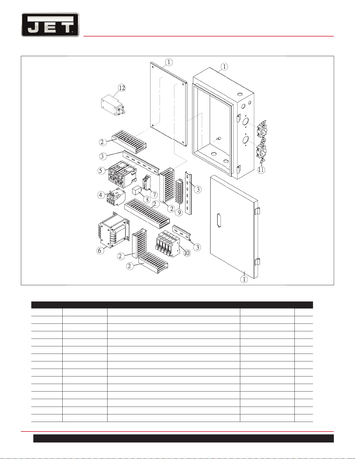
42
MILL
ELECTRICAL ASSEMBLY — ETM–949
ELECTRICAL PARTS LIST — ETM-949
Index No. Part No. Description Size Qty.
1 ETM949-E01 Electric Box Assembly 1
2 ETM949-E02 Wire Housing 3
3 ETM949-E03 Aluminum Plate 2
4 ETM949-E04 Overload (ETM949 only) 7.2-10A 1
5 ETM949-E05 Magnetic Switch CU11 1
6 ETM949-E06 Transformer 1
7 ETM949-E07 Relay Switch Base 1
8 ETM949-E08 Relay Switch 1
9 ETM949-E09 Terminal Block Plate 1
10 ETM949-E10 Fuse Base 5
ETM949-F2A Fuse (not shown) 2A 1
ETM949-F4A Fuse (not shown) 4A 1
ETM949-F20A Fuse (not shown) 20A 3
11 ETM949-E11 Power Socket 2
12 ETM949-E19 Limit Switch 1
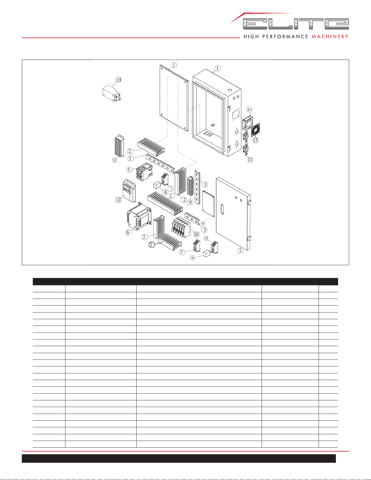
43
ETM–949 | ETM–949EVS
INVERTER ELECTRICAL ASSEMBLY — ETM–949EVS
INVERTER ELECTRICAL PARTS LIST — ETM-949EVS
Index No. Part No. Description Size Qty.
1 ETM949EVS-E01 EVS Inverter Electric Box Assembly 1
2 ETM949-E02 Wire Housing 2
3 ETM949-E03 Aluminum Plate 2
5 ETM949-E05 Magnetic Switch (serial No. 13080024 and lower) CU11 1
ETM949-E05N Magnetic Switch (serial No. 14070035 and higher) CU18 1
6 ETM949-E06 Transformer 1
7 ETM949-E07 Relay Switch Base AC24V 2
8 ETM949-E08 Relay Switch AC24V 1
9 ETM949-E09 Terminal Block Plate 1
10 ETM949-E10 Fuse Base 5
ETM949-F2A Fuse (not shown) 2A 1
ETM949-F4A Fuse (not shown) 4A 1
ETM949-F20A Fuse (not shown) 20A 3
ETM949EVS-F25A Fuse (not shown)(option) 25A 2
11 ETM949EVS-E11 Heatsink 1
12 ETM949EVS-E12 Inverter
(serial No. 13080024 and lower) 230V 3PH E type 1
ETM949EVS-E12-1PH Inverter
(serial No. 14070035 and higher) 230V 1/3PH B type 1
13 ETM949-E11 Power Socket 2
14 ETM949EVS-E14 Fan 1
15 ETM949EVS-E15 Filter 1
16 ETM949EVS-E16 Relay Switch DC24V 1
17 ETM949EVS-E17 Relay Switch Base DC24V 1
18 ETM949EVS-E18 PC board 1
19 ETM949-E19 Limit Switch 1
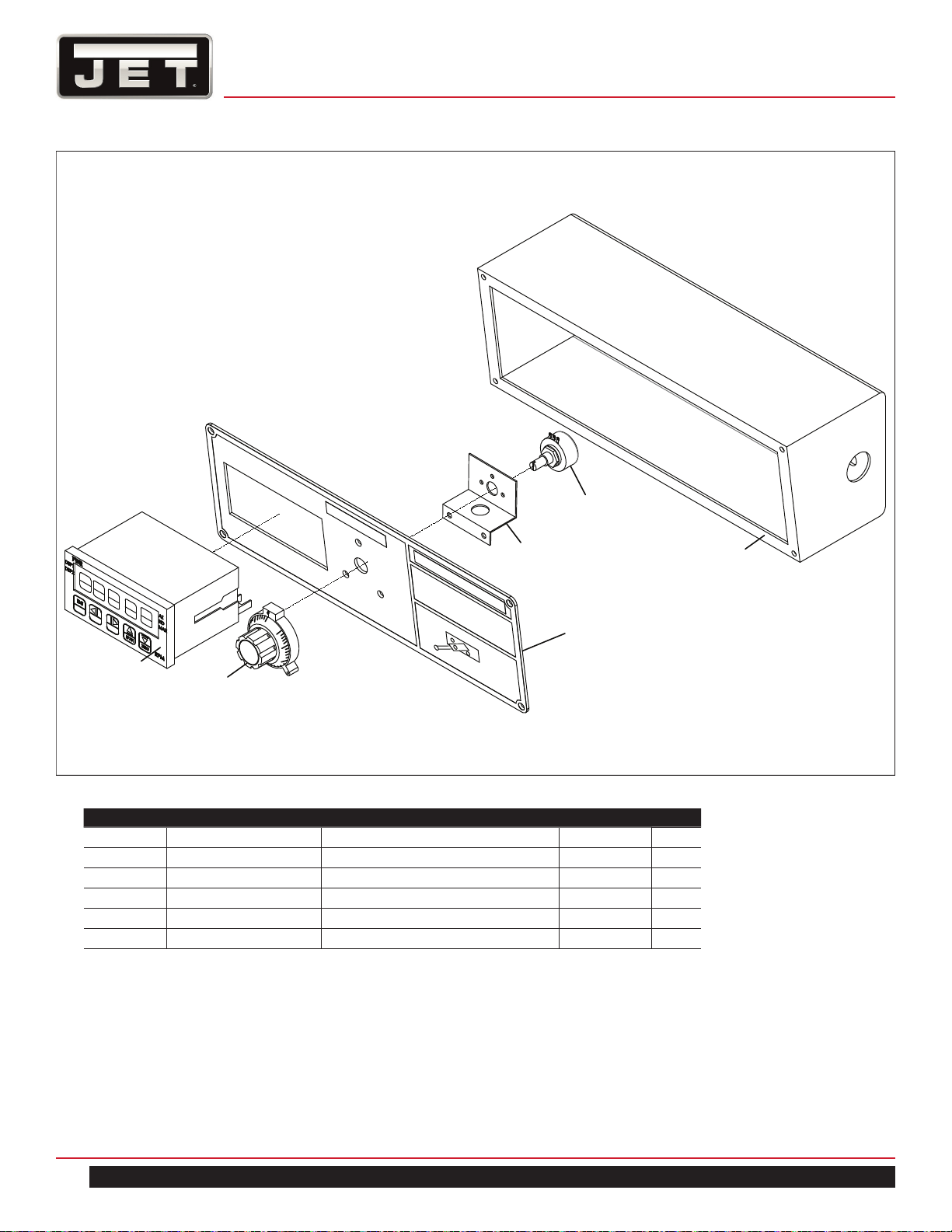
44
MILL
HEAD CONTROL PANEL — ETM–949EVS
1
2
5
6
3
4
HEAD CONTROL PANEL PARTS LIST
Index No. Part No. Description Size Qty.
1 ETM949EVS-D100 Control Box for EVS 1
2 ETM949EVS-D102 Control Panel for EVS 1
3 ETM949EVS-F03 VR Knob 1
4 ETM949EVS-F04 Digital Readout 1
5 ETM949EVS-F05 Metal Plate 1
6 ETM949EVS-F06 VR Variable Resistor 1
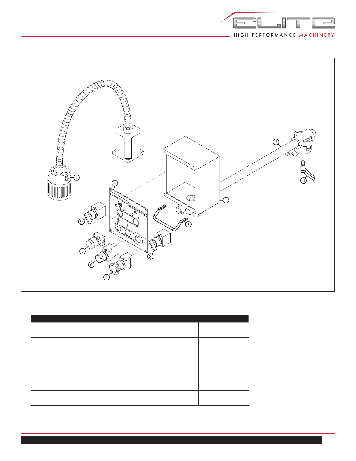
45
ETM–949 | ETM–949EVS
CONTROL PANEL ASSEMBLY — ETM–949, ETM–949EVS
CONTROL PANEL ASSEMBLY PARTS LIST
Index No. Part No. Description Size Qty.
1 ETM949-G01 Control Panel Box 1
2 ETM949-G02 Support Bar Assembly 1
3 ETM949-G03 Work Lamp 1
4 ETM949-G04 Control Panel label 1
5 ETM949-G05 Emergent Switch 1
6 ETM949-G06 Start Switch 1
7 ETM949-G07 Power Light 1
8 ETM949-G08 Coolant Pump Switch * 1
9 ETM949-G09 F/R Switch 1
10 ETM949-G10 Handle 1
11 ETM949-G11 Knob 1
* optional accessory, supplied with 894092 Coolant System
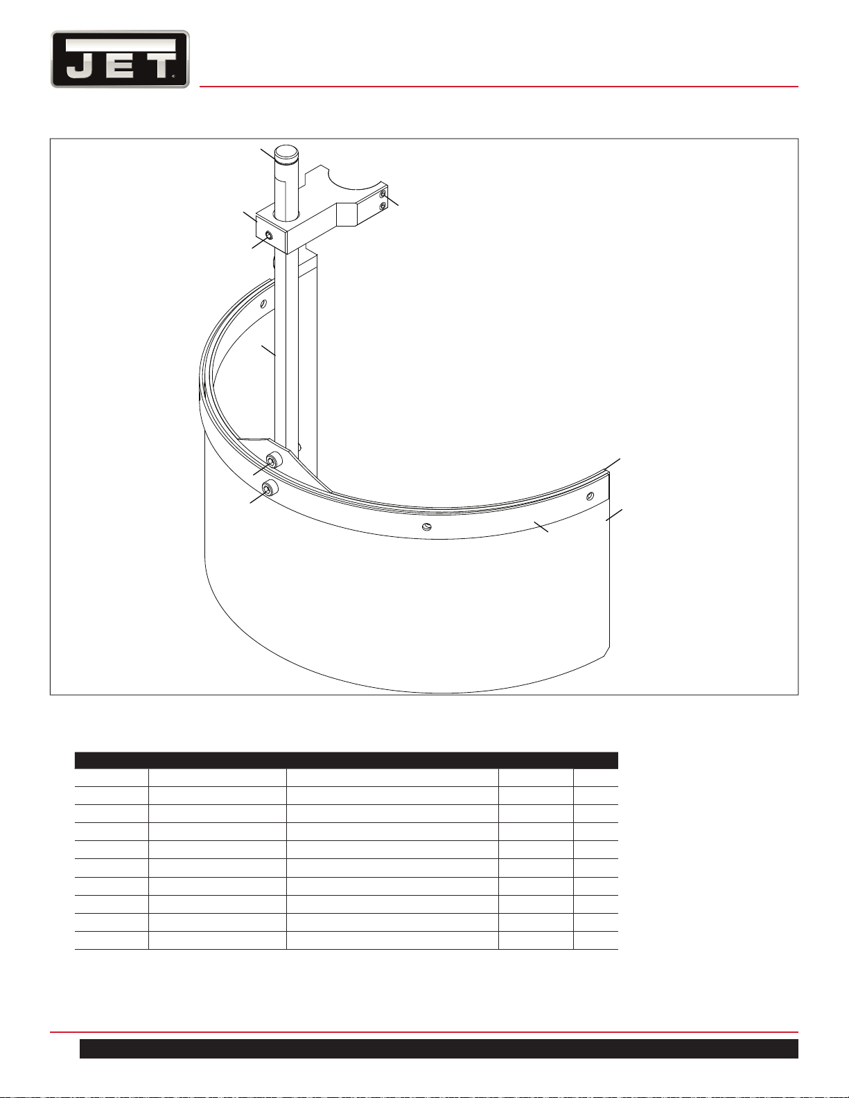
46
MILL
SPINDLE SHAFT GUARD ASSEMBLY — ETM–949, ETM–949EVS
1
2
3
4
9
10
8
6
5
7
SPINDLE SHAFT GUARD PARTS LIST
Index No. Part No. Description Size Qty.
1 ETM949-H01 Snap Ring C-Type S-16 1
2 ETM949-H02 Cover 1
3 TS-1503021 Set Screw M6x10 1
4 ETM949-H04 Shaft 1
5 TS-1502051 Hex Socket Head Cap Screw M5x20 1
6 ETM949-H06 Guard mounting plate (I) 1
7 ETM949-H07 Guard mounting plate (II) 1
8 ETM949-H08 Guard 1
9 ETM949-H09 Hex Socket Head Cap Screw M6x15 1
10 TS-1503051 Hex Socket Head Cap Screw M6x20 1
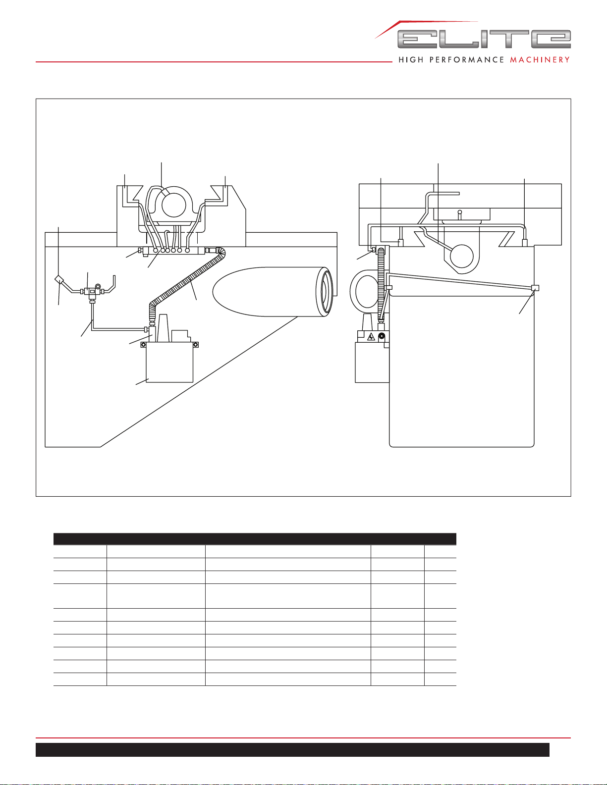
47
ETM–949 | ETM–949EVS
LUBRICATION SYSTEM ASSEMBLY — ETM–949, ETM–949EVS
R-Cross Slide Way
Cross Slide Way
L-Cross Slide Way
Cross Feed Nut Bracket
L-Knee Slide Way
F- Longitudinal Slide Way
Longitudinal Feed Nut Bracket
B- Longitudinal Slide Way
7
4
9
3
5
2
6
1
8
LUBRICATION SYSTEM PARTS LIST
Index No. Part No. Description Size Qty.
1 ETM949-B79 Automatic Oiler 1
2 ETM949-I02 Aluminum Pipe 1
3 ETM949-I03 Oil Regulating Distributor 1
3A ETM949-I03A Oil Regulating Distributor Assembly
(includes #3-5, 7-9)
1
4 ETM949-I04 T-Joint 1
5 ETM949-I05 Flexible Steel Tube 1
6 ETM949-I06 Check Joint 2
7 ETM949-I07 Elbow Joint 2
8 ETM949-I08 Straight Joint 14
9 ETM949-I09 Union 1
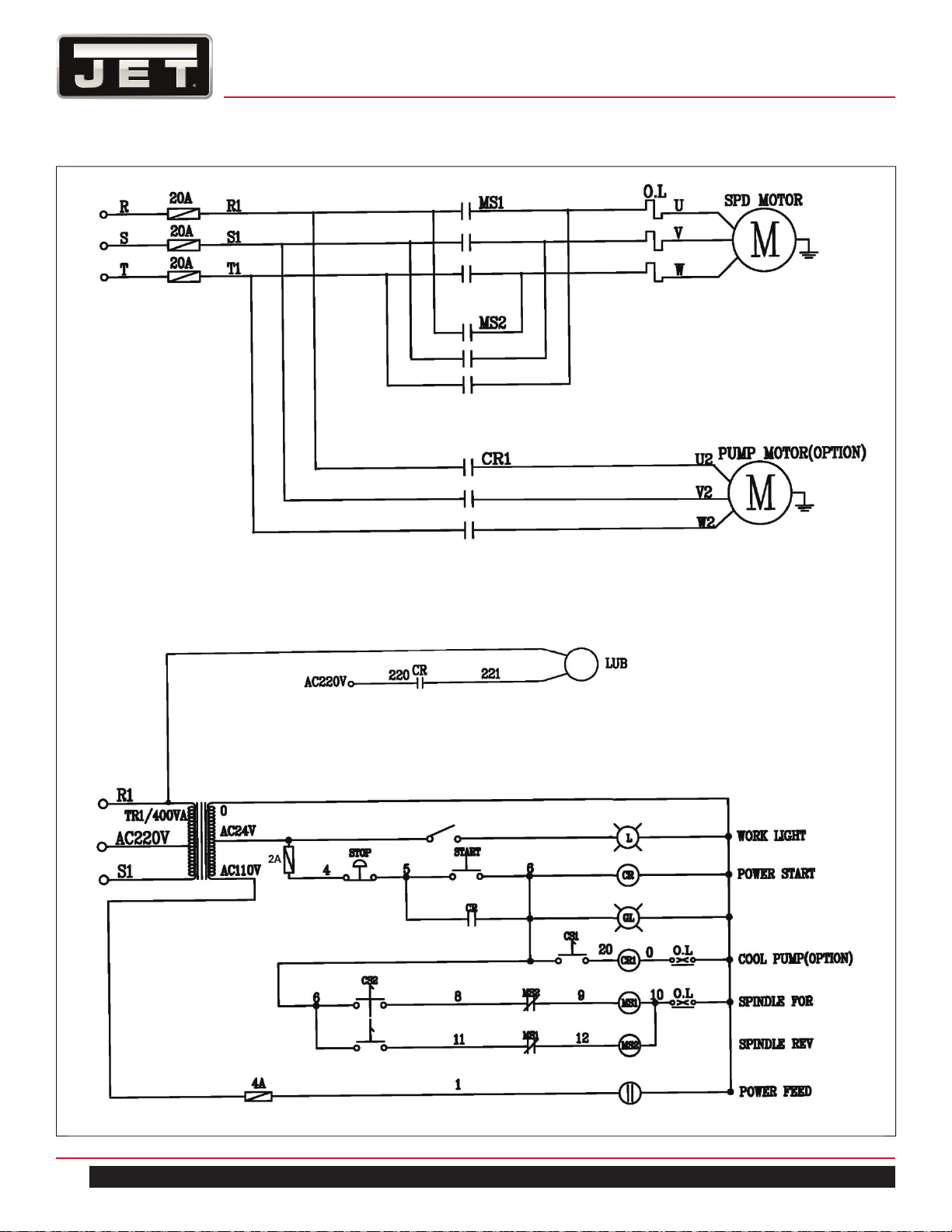
48
MILL
14.0 WIRING DIAGRAM — ETM-949
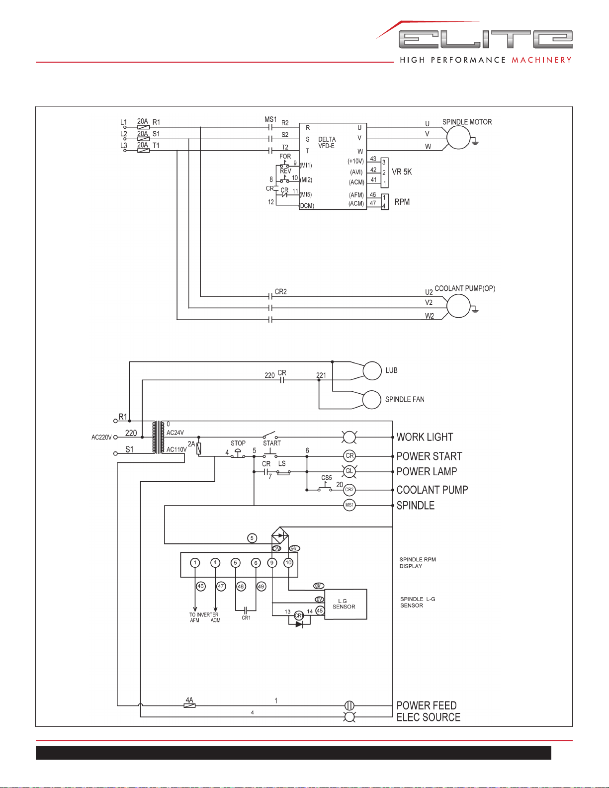
49
ETM–949 | ETM–949EVS
WIRING DIAGRAM — ETM-949EVS (E type inverter)
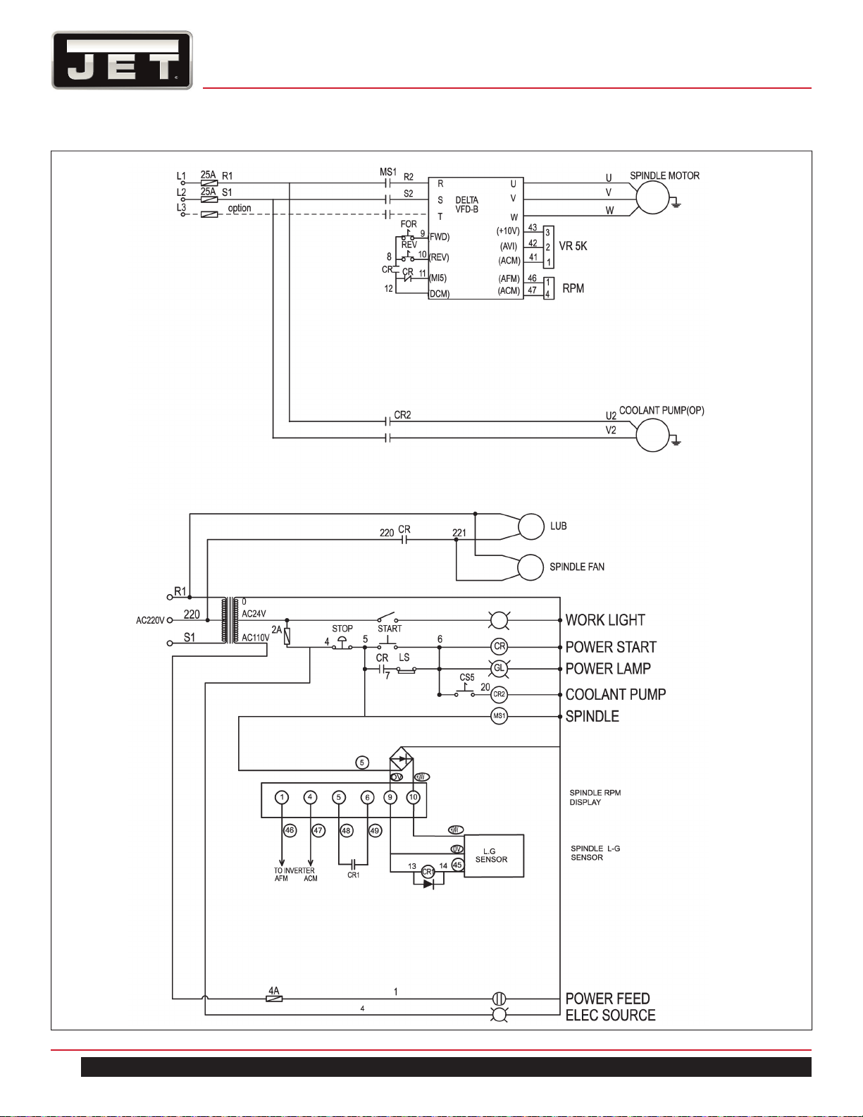
50
MILL
WIRING DIAGRAM — ETM-949EVS (B type inverter)

51
ETM–949 | ETM–949EVS
NOTES

52
MILL
NOTES