
User’s Manual
I
European Standard Electric Vehicle Charger
User’s Manual
V1.0.0
ZHEJIANG DAHUA VISION TECHNOLOGY CO., LTD.
User’s Manual
I
Foreword
General
This manual introduces the installation, functions and operations of the electric vehicle charger
(hereinafter referred to as the "EV Charger"). Read carefully before using the device, and keep the
manual safe for future reference.
Safety Instructions
The following signal words might appear in the manual.
Signal Words Meaning
DANGER
Indicates a high potential hazard which, if not avoided, will result in death
or serious injury.
WARNING
Indicates a medium or low potential hazard which, if not avoided, could
result in slight or moderate injury.
CAUTION
Indicates a potential risk which, if not avoided, could result in property
damage, data loss, reductions in performance, or unpredictable results.
TIPS
Provides methods to help you solve a problem or save time.
NOTE
Provides additional information as a supplement to the text.
Revision History
Revision Content Release Time Revision Content
V1.0.0 First release. April 2023

User’s Manual
II
Important Safeguards and Warnings
This section introduces content covering the proper handling of the device, hazard prevention, and
prevention of property damage. Read carefully before using the device, comply with the guidelines
when using it, and keep the manual safe for future reference.
Transportation Requirements
When you transport or move the EV Charger, please note the following safeguards to ensure product
safety.
The EV Charger is an electrical device. Please operate it in locations that will not expose it to
violent vibrations and shocks.
When transporting the EV Charger, do not place heavy stress on the front glass panel.
Do not transport the EV Charger by dragging the charging connector or charging cable.
Storage Requirements
Do not place flammable or explosive materials near the EV Charger. Otherwise, an explosion might
occur.
Do not place the EV Charger in a location that exposes it to direct sunlight or heat sources.
Keep all the original packing materials in case you need to pack and send the EV Charger back
for repairs. Pack the EV Charger with packaging material that comes with it. If the EV Charger
sustains accidental damage during transportation due to incorrect packaging, the owner must
bear responsibility.
Installation Requirements
All service personnel must have required certification or qualified training for performing
installations and maintenance of EV chargers. They must also have knowledge and skills in the
following areas:
Basic knowledge and skills in installing the EV Charger and its components.
Basic knowledge and skills in low-voltage wiring and in connecting low-voltage electronic
circuits.
The ability to read and understand this manual.
Safety protection is a must when installing the EV Charger.
Installation and wiring must be carried out by professionals to avoid electric shocks.
The power must be cut off before wiring to avoid electric shocks.
Strictly comply with the local electrical safety code and standards when performing installation
and other operations.

User’s Manual
III
The grounding terminal of the EV Charger must be correctly grounded to avoid electric shocks.
Do not leave bolts, washers, or other metals inside the EV Charger to avoid explosions and fire.
The exposed parts of the cable terminal must be wrapped with insulation tape to avoid fire and
property damage.
The post of the EV Charger must be installed on non-combustible materials, such as concrete, to
avoid fire breaking out.
Do not install the EV Charger in areas containing explosive gases. Otherwise, explosion might
occur.
Do not install the EV Charger in areas containing explosive gases to avoid explosions.
An emergency disconnect device must be installed during installation and wiring.
The front cover must be properly closed to avoid damage to the EV Charger.
The main loopback terminal of the EV Charger must be firmly connected to the wiring interface
to avoid property loss.
Do not install the EV Charger in an environment that might expose it to vibrations, shocks and
electromagnetic interference, to avoid it sustaining damage.
Install the EV Charger away from an environment that is saturated with water or other liquids.
Do not install the EV Charger in a location that exposes it to sunlight or heat sources.
To make the EV Charger work stably for a long time, do not install it in harsh weather. Expansion
due to heat or contraction due to cold might affect the installation process.
We recommend that you install the EV Charger in a well-ventilated place that is windproof and
rainproof. To ensure good ventilation, it should be installed vertically, leaving enough space for
ventilation.
The EV Charger should be installed in an area that does not have conductive dust and insulating
destructive gases or steam.
The installation foundation should be higher than the ground, and drainage ditches should be
set around the EV chargers, to avoid device damage.
Operation Requirements
An electric vehicle can only be charged when it is stationary with its engine off.
Minors and persons with limited ability are strictly prohibited from approaching the EV Charger
to avoid injury.
Force charging is strictly prohibited when the electric vehicle or the EV Charger fails.
In the event of an emergency (such as fire, smoke, abnormal noise, and water leakage), for your
personal safety, press the red emergency button and immediately move away from the EV
Charger. Contact the supplier afterwards.
When the charging adapter or the charging cable is defective, cracked, worn, broken, or the
charging cable is exposed, it is forbidden to use the EV Charger. If you find any of the above
problems, please contact the supplier.
Electric vehicles are not allowed to be charged during rains or thunderstorms.
Strictly comply with the local electrical safety code and standards when performing operations.
Use the power adapter provided by a certified manufacturer. See the specification for details.
To reduce the risk of fire and electric shock, do not expose the EV Charger to rain and damp
environments.

User’s Manual
IV
Do not place the EV Charger in a humid, dusty, extremely hot or cold site that is corrosive. For
details on the temperature and humidity requirements, see the specifications.
Ensure the EV Charger has adequate ventilation for heat dissipation.
Maintenance Requirements
Maintenance personnel must have required certification or qualified training for installing and
maintaining the EV Charger. They must also have knowledge and skills in the following areas.
Basic knowledge and skills in installing the EV Charger and its components.
Basic knowledge and skills in low-voltage wiring and in connecting low-voltage electronic
circuits.
The ability to read and understand this manual.
Personnel must wear protective shoes at all times during maintenance.
Accessories replacement must be performed by professionals. It is strictly prohibited to leave
wire or metal in the controller. Otherwise, explosion and fire might occur.
Accessories must be replaced by professionals. To avoid explosions and fire, wires and metals
are prohibited from being left in the controller of the EV Charger.
Contact your local retailer or customer service center if the EV Charger works abnormally. Do
not disassemble or repair the EV Charger by yourself. The company is not responsible for
problems caused by unauthorized modifications and repairs.
After replacing the main PCBA, adjust and match the parameters before you perform operations,
to avoid property damage.
We recommend you conduct routine safety checks on the EV Charger at least once a week.
To ensure the EV Charger functions for a long time, periodically perform maintenance on it
(usually monthly) based on the environment it is installed in.
The EV Charger should be maintained by professionals.
Check whether the EV Charger is correctly grounded and safe.
Check whether there are potential safety risks around the post of the EV Charger. Ensure
the EV Charger is not in an extremely hot, corrosive environment that has flammable and
explosive materials.
Check whether the connection points of the input terminals are in good contact and
whether there are abnormalities.
Check whether other connection points are loose.
Keep the connector clean and dry. If there is dirt, wipe it away with a clean and dry cloth after
powering off the EV Charger.

User’s Manual
V
Table of Contents
Foreword ............................................................................................................................................................ I
Important Safeguards and Warnings .............................................................................................................. II
1 Product Introduction .................................................................................................................................... 1
Product Overview ...................................................................................................................................................................... 1 1.1
Main Features .............................................................................................................................................................................. 1 1.2
Charging Information ............................................................................................................................................................... 1 1.3
1.3.1 Charging Mode .............................................................................................................................................................. 1
1.3.2 Charging Connection .................................................................................................................................................. 1
2 Unpacking and Structure .............................................................................................................................. 3
Unpacking..................................................................................................................................................................................... 3 2.1
Dimensions ................................................................................................................................................................................... 3 2.2
Structure ........................................................................................................................................................................................ 4 2.3
3 Installation and Network Configuration ...................................................................................................... 5
Installation Notes ....................................................................................................................................................................... 5 3.1
Preparation ................................................................................................................................................................................... 5 3.2
Installing and Configuring the EV Charger ....................................................................................................................... 6 3.3
3.3.1 Wall Mount ...................................................................................................................................................................... 6
3.3.2 Floor Standing ................................................................................................................................................................ 9
4 Operation ..................................................................................................................................................... 12
Web Operation .......................................................................................................................................................................... 12 4.1
4.1.1 Logging in to the Webpage .................................................................................................................................... 12
4.1.2 Changing the Password ............................................................................................................................................ 12
4.1.3 Changing Charging Mode ....................................................................................................................................... 13
4.1.4 Modifying Time ............................................................................................................................................................ 13
4.1.5 Configuring a New RFID Card ................................................................................................................................. 14
4.1.6 Changing the QR Code on the Screen ................................................................................................................ 15
4.1.7 Upgrading the Program ........................................................................................................................................... 15
4.1.8 Restarting the EV Charger ....................................................................................................................................... 15
4.1.9 Restoring Factory Default ........................................................................................................................................ 16
4.1.10 Changing the Network Mode of the EV Charger .......................................................................................... 16
4.1.11 Connecting to Management Platform through 4G ..................................................................................... 17
4.1.12 Adjusting the Charging Current ......................................................................................................................... 18
4.1.13 Using Current Transformer .................................................................................................................................... 19
4.1.14 Configuring APN of SIM Card ............................................................................................................................... 19
4.1.15 Changing Wi-Fi Password ...................................................................................................................................... 21
Charging the Vehicle ............................................................................................................................................................... 22 4.2
Stopping Charging ..................................................................................................................................................................
22 4.3
5 Troubleshooting .......................................................................................................................................... 23
Abbreviations ............................................................................................................................. 24 Appendix 1
Cybersecurity Recommendations ............................................................................................. 25 Appendix 2

User’s Manual
1
1 Product Introduction
Product Overview 1.1
This alternating current electric vehicle charger belongs to the special alternating current (AC) power
supply device for electric vehicles. It provides a 3.5-inch LCD screen, and is designed with a friendly
interface with corresponding control, communication and other functions.
The EV Charger is suitable for a variety of scenes that offer 230 VAC power supply. It is widely used for
charging all kinds of household electric vehicles, as well as various charging stations, parking lots,
community garages and public electric vehicle charging places.
Main Features 1.2
Supports 3 charging modes: free vending (plug & play), RFID control, and app control.
Supports operation status monitoring, fault status monitoring, charging metering and linkage
control of charging process, and more.
Reliable security monitoring to prevent short circuit, surge, over temperature, overvoltage,
undervoltage, overcurrent, and leakage.
Displays the charging current, charging voltage, charging power, charging time, status, failure
information and more.
Supports QR code scanning.
A 3-color LED indicator that will show different status of the EV Charger.
RFID card identification for convenient charging.
The EV Charger provides a plug that is applicable to models with charging ports of European
standard.
Supports various ways of connection, such as Ethernet (RJ-45 interface), Wi-Fi (2.4 GHz), cellular,
and more.
Charging Information 1.3
1.3.1 Charging Mode
The EV Charger conforms to EN IEC 61851-1:2019, and it uses charging mode 3 (AC charging with a
stationary charging point), which is a method that connects an electric vehicle (EV) to an AC EV
supply equipment and then provides AC power to the EV.
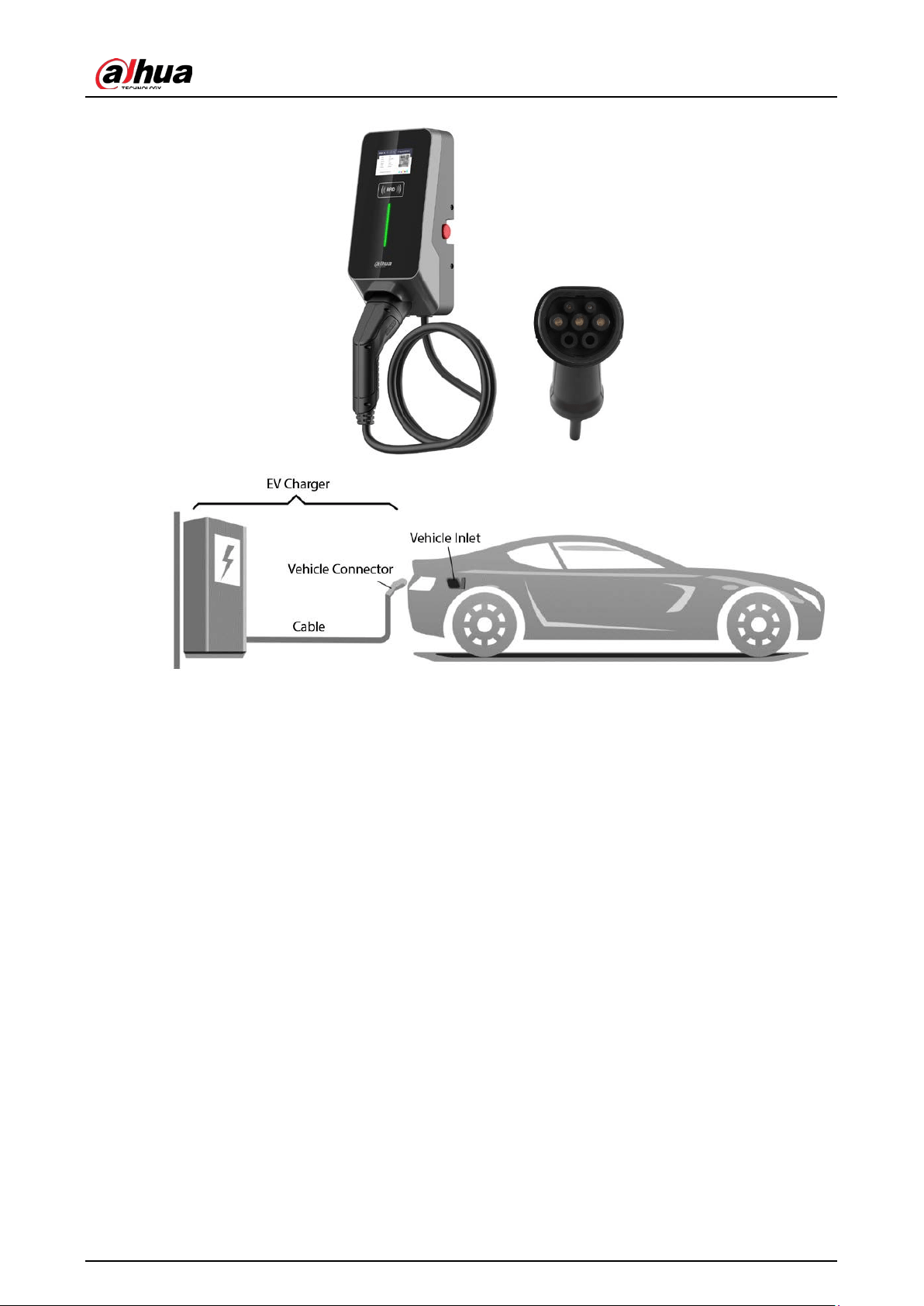
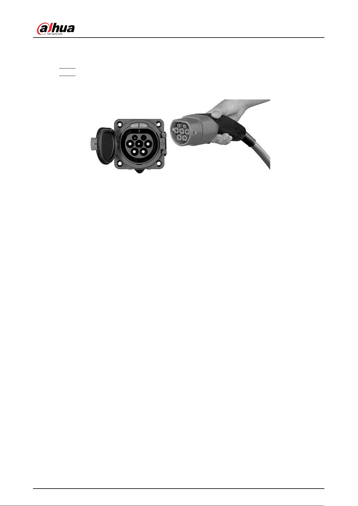
1.3.2 Charging Connection
According to EN IEC 61851-1:2019, the EV Charger uses type 2 tethered cable and meets case C
connection, which connects an EV to a supply network utilizing a cable and vehicle connector
permanently attached to the EV charger.
User’s Manual
2
Example of type 2 tethered cable Figure 1-1
Example of case C connection Figure 1-2
User’s Manual
3
2 Unpacking and Structure
Unpacking 2.1
When unpacking the package, carefully confirm that:
Whether the accessories are missing according to the packing list.
Whether there is any damage during transportation.
Whether the model and specifications on the device label are consistent with the order
requirements.
If any damage or missing parts are found, do not start the EV Charger. Contact the supplier as soon
as possible, and keep the packing box and packing materials for after-sales service.
Table 2-1 Packing list
Package Quantity
AC EV charger 1 piece
RFID card 2 pieces
Mounting accessories (including screws) 1 set
Quick start guide 1 piece
QR codes for acquiring user's manual, downloading Android app and iOS app 1 piece
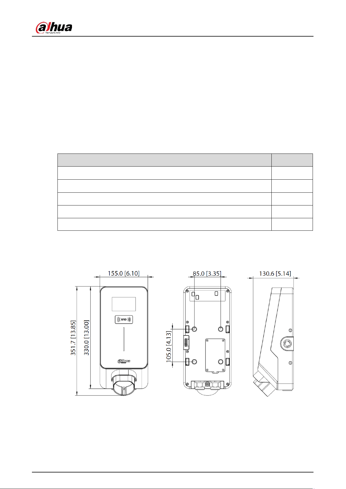
Dimensions 2.2
Dimensions (mm [inch]) Figure 2-1
User’s Manual
4
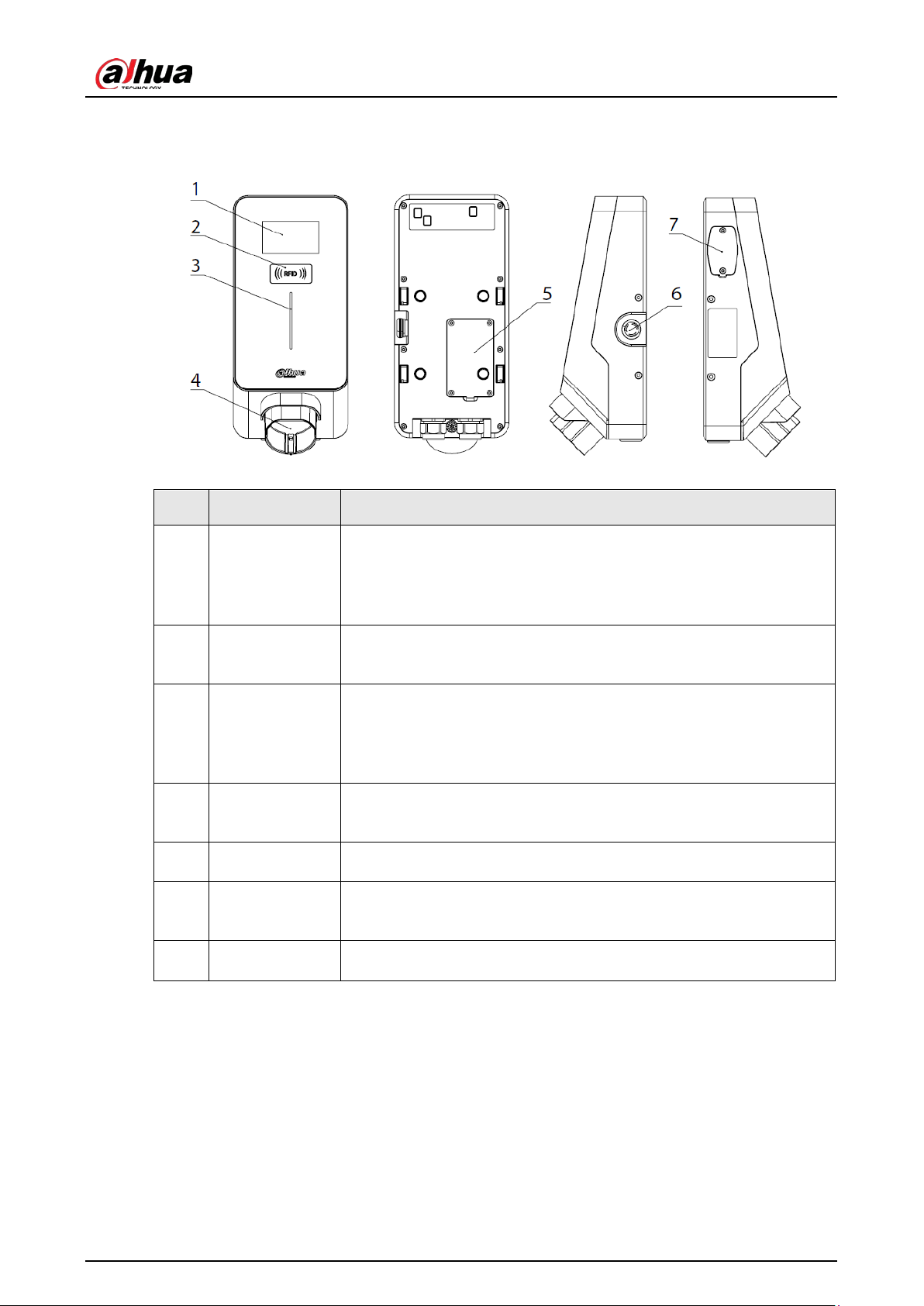
Structure 2.3
Structure Figure 2-2
Table 2-2 Structure description
No. Name Description
1 LCD screen
3.5-inch LCD screen that displays network connection, date and time,
charging status, welcome message and version informatin.
When the EV Charger is idle, ready, faulted, the vehicle is charging or
charged, Status shows Available, Preparing, Faulted, Charging, or
Finished respectively.
2 RFID reader
The EV Charger is equipped with RFID card reader by default. You can
swipe the RFID card that comes with the EV Charger on the RFID card
reader to start or stop the charging process.
3 LED indicator
Indicates different status of the EV Charger.
Solid blue: Standby.
Yellow: The EV Charger is plugged in, or a card is swiped.
Light green: Charging.
Flashes red: Fault.
4
Type 2 in-body
holster
Used for holding and fixing the charging cable of the EV Charger.
5 Rear cover plate
Open the rear cover plate, and then you will find L, N, and PE ports to
connect the power cable, RJ-45 network port, and CT port.
6
Emergency
button
When an emergency occurs, you can press this button to stop
charging. To restore charging, rotate the button clockwise.
7 Side cover plate
Open the side cover plate, and then you will find the SIM card slot, dial
button for network connection (N1, N2), USB port, and KEY button.
User’s Manual
5
3 Installation and Network Configuration
Installation Notes 3.1
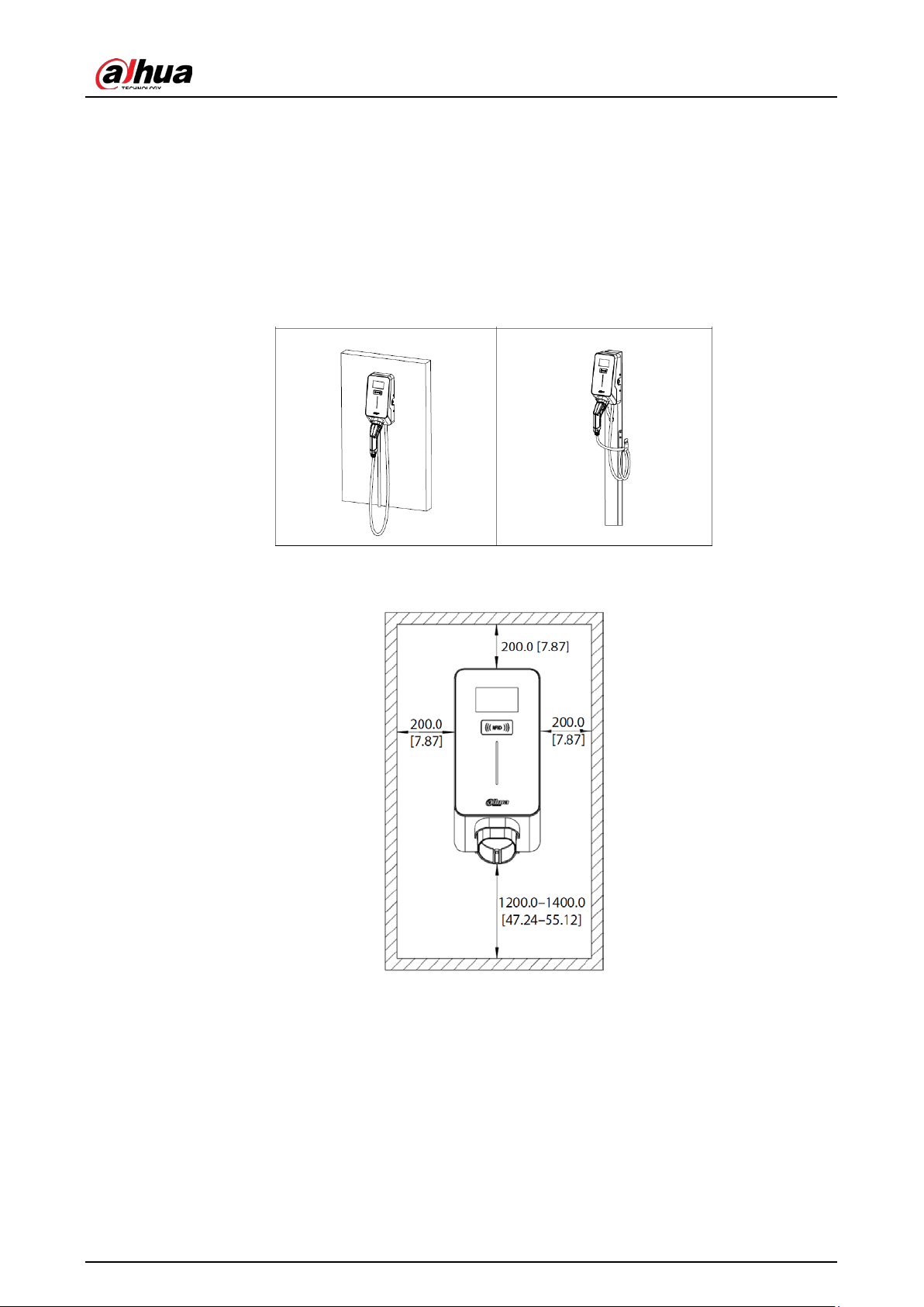
The EV Charger supports 2 installation methods: wall mount and floor standing.
For floor-standing installation, you need to purchase the mounting bracket separately.
Installation methods Figure 3-1
Wall Mount
Floor Standing
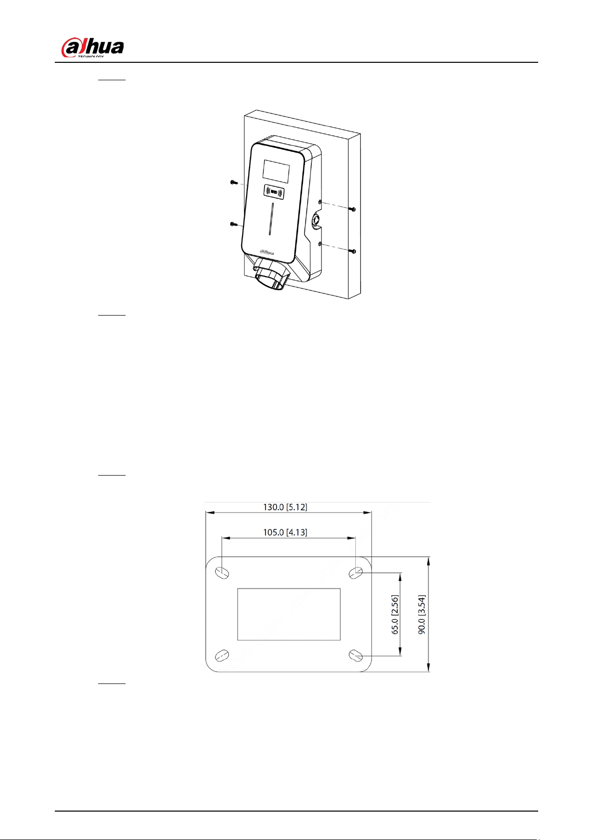
When the EV Charger is fixed to the wall, the minimum space requirements are shown in the
following figure.
Minimum space requirements for wall mounting (mm [inch]) Figure 3-2
Preparation 3.2
Prepare a computer for configuring the network of the EV Charger.
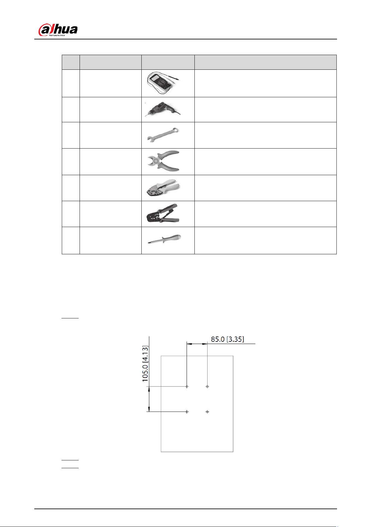
Prepare the following installation tools before installing the EV Charger.
User’s Manual
6
Table 3-1 Installation tools
No. Tool Image Usage
1 Multimeter
Check the electrical connection and measure the
voltage.
2 Electric impact drill
Drill fixing holes in the wall.
3 Wrench
Fastening bolt.
4 Diagonal plier
Cut the cable.
5 Wire stripper
Peeling cables.
6 Crimping plier
Pressed cable terminal.
7 Cross screwdriver
Fasten screws.
Installing and Configuring the EV Charger 3.3
3.3.1 Wall Mount
Drill 4 mounting holes with diameter of 8 mm and depth of 65 mm at an appropriate height, Step 1
with the spacing of holes shown in the following figure.
Spacing of holes (mm [inch]) Figure 3-3
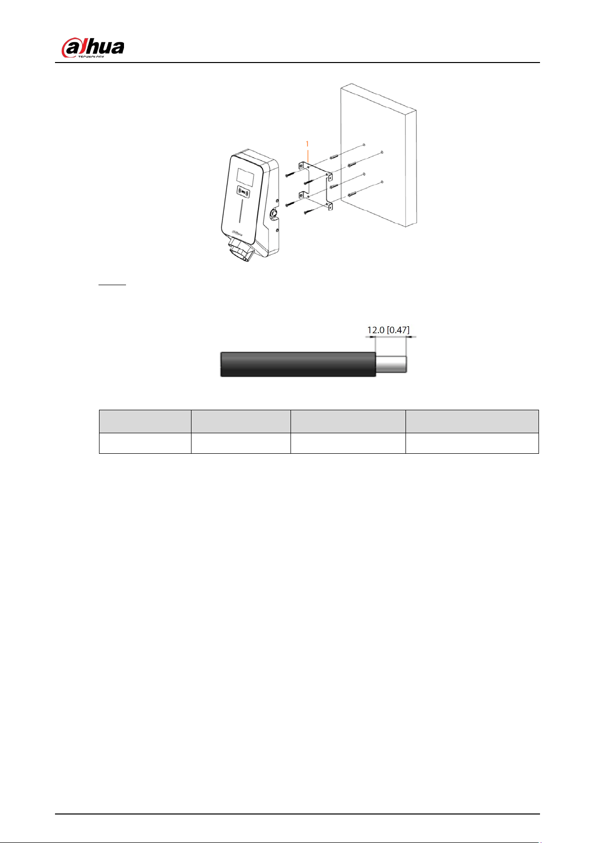
Fix the mounting accessories to the wall with the expansion screws in the package. Step 2
Use 4 screws (M6 × 60) to fix the mounting bracket (1 show in the following figure) to the Step 3
wall.
User’s Manual
7
Fix the mounting bracket to the wall Figure 3-4
1: mounting barcket.
Wiring. Step 4
1) Use a wire stripper to strip off the insulation layer of the cable (hardline cables are
recommended).
Stripe off the insulation layer (mm [inch]) Figure 3-5
Requirements on cable size are as below:
Table 3-2 Cable size
Rated Current Rated Power Input Terminals Cable Size Requirement
32 A 7 kW L/N/PE Copper, 3 × 6 mm
2
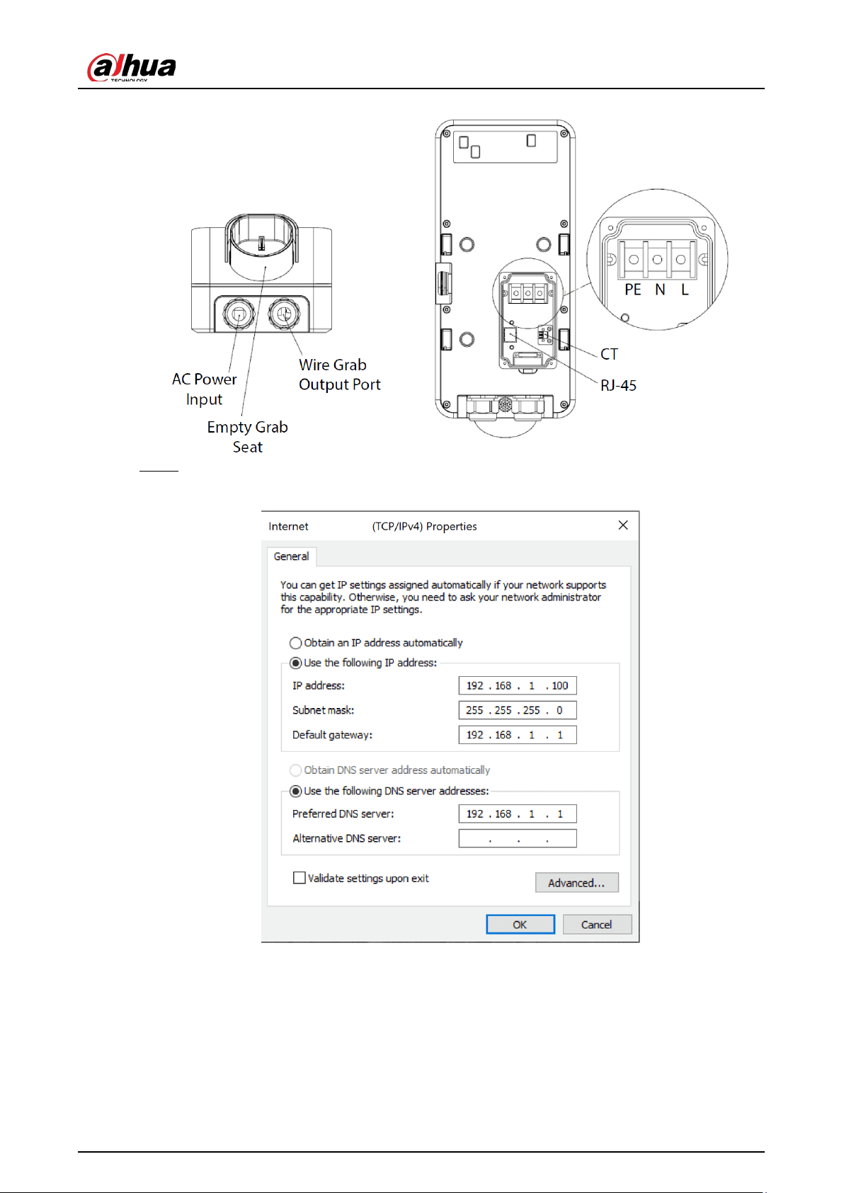
2) Thread the stripped cable through the cable inlet port at the bottom of the EV Charger,
and connect each cable to the cable inlet terminal inside the EV Charger.
Connect the live wire, neutral wire, and ground wire to the L, N, and PE cables
respectively.
After connecting the wires, secure the cable cover, and ensure that the junction
box does not leak.
If you need to connect the EV Charger to an Ethernet cable, you can connect the
network cable to the RJ-45 port at the bottom of the EV Charger.
User’s Manual
8
Wiring Figure 3-6
Configuring the parameters. Step 5
1) Set the network information of your computer as shown in the following figure.
Configure network parameters of your computer Figure 3-7
2) Connect your computer to the EV Charger through the RJ-45 port on the EV Charger.
3) Switch N1 and N2 under the left-side cover plate of the EV Charger to ON.
4) Power on the EV Charger.
After installing the EV Charger and connecting the live wire, neutral wire, and ground
wire to the L, N, and PE cables respectively, connect the EV Charger to power. The LED
indicator shows blue, meaning that the EV Charger is in standby status.
5) Refer to "4.1.1 Logging in to the Webpage" and "4.1.2 Changing the Password" to log in
and change the default password.
User’s Manual
9
Attach the EV Charger to the mounting bracket, and then use 4 M4 × 10 screws to fix the 2 Step 6
sides of the EV Charger.
Fix the EV Charger to the mounting bracket Figure 3-8
(Optional) Install the SIM card. Step 7
Home EV charger: No need to install the SIM card.
EV charger for charge point operator (CPO): Purchase the SIM card from the CPO, and
then insert the SIM card into the SIM card slot. For the 7 kW EV charger, open the
left-side cover plate, and then you will see the SIM card slot.
3.3.2 Floor Standing
Install the EV Charger at the proper position of the parking spot. We recommend that you install the
EV Charger on the concrete ground. If the EV Charger is installed in an area where expansion screws
cannot be used, such as the lawn, drill a hole and pour cement. Make sure that the dimensions of the
hole cannot be smaller than 300 mm × 300 mm × 200 mm.
Drill 4 holes with dimensions as shown in the following figure, diameter of Φ12 mm and Step 1
depth of 105 mm.
Dimensions of hole (mm [inch]) Figure 3-9
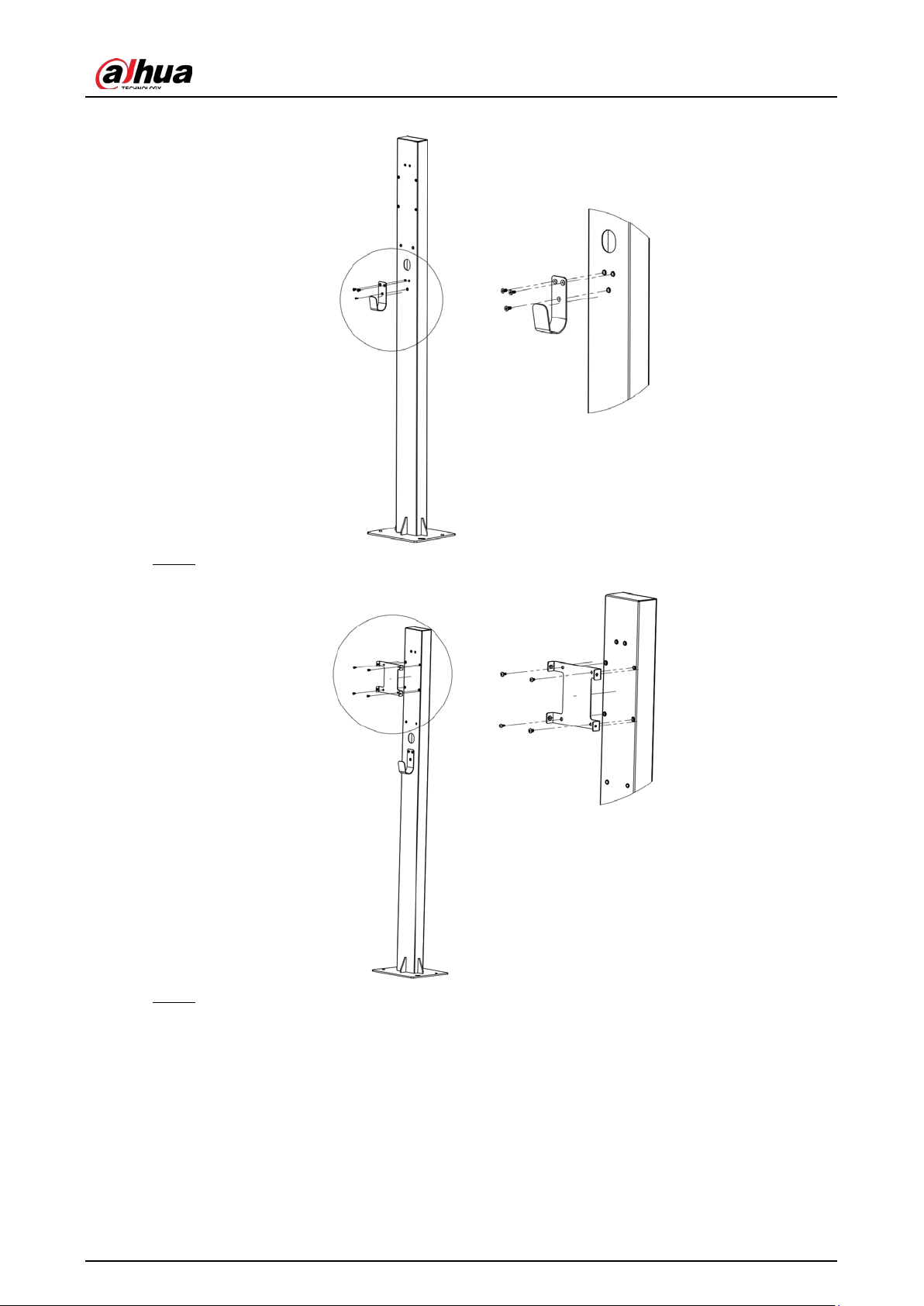
Use 3 M4 × 10 screws to install the mounting hook on the mounting bracket. Step 2
User’s Manual
10
Mounting hook Figure 3-10
Use 4 M4 × 10 screws to secure the mounting plate to the mounting bracket. Step 3
Secure mounting bracket Figure 3-11
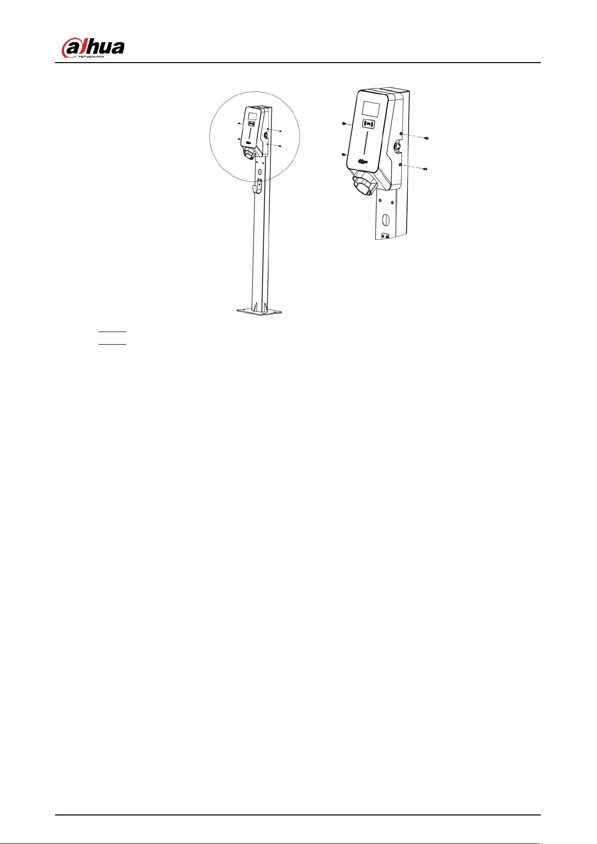
Fix the EV Charger to the mounting bracket, and then use 4 M4 × 10 screws to fix both sides Step 4
of the EV Charger.
The installation is complete.
User’s Manual
11
Fix EV Charger Figure 3-12
Configure the parameters. Refer to Step 5 in "3.3.1 Wall Mount". Step 5
(Optional) Install the SIM card. Step 6
Home EV charger: No need to install the SIM card.
EV charger for CPO: Purchase the SIM card from the CPO, and then insert the SIM card
into the SIM slot. For the 7 kW EV charger, open the left-side cover plate, and then you
will see the SIM slot.
User’s Manual
12
4 Operation
Web Operation 4.1
4.1.1 Logging in to the Webpage
Logging in to the Webpage by Connecting to Network Cable
We recommend using network cable to connect to the network, and then log in to the webpage.
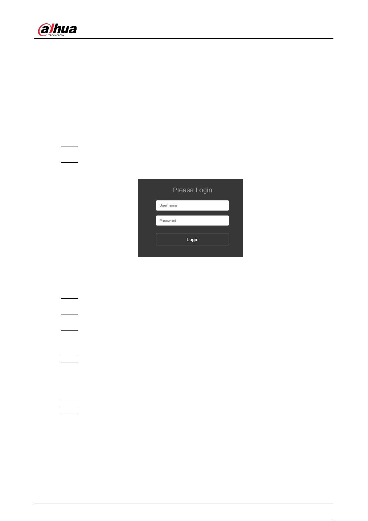
Enter http://192.168.1.253/index.html in the browser address bar, and then press the Enter Step 1
key.
Enter login username and password (root and root@123456 respectively), and then click Step 2
Login.
Login Figure 4-1
Logging in to the Webpage in AP Mode
If network cable connection is inconvenient, you can perform the following operations to log in to
the webpage in AP mode.
Switch N1 and N2 under the left-side cover plate of the EV Charger to ON, and then power Step 1
on the EV Charger.
On your computer, set Networking parameters: Select Internet Protocol Version 4 Step 2
(TCP/IPv4), and then select Obtain an IP address automatically.
Connect to WLAN: In network settings, find the network named evse-…, click Connect, and Step 3
then enter the password, which is root@123456.
It might take some time for the computer to search the evse-... network.
Enter http://192.168.4.1/index.html in the browser address bar, and then press the Enter key. Step 4
Enter the username and password, and then click Login. Step 5
4.1.2 Changing the Password
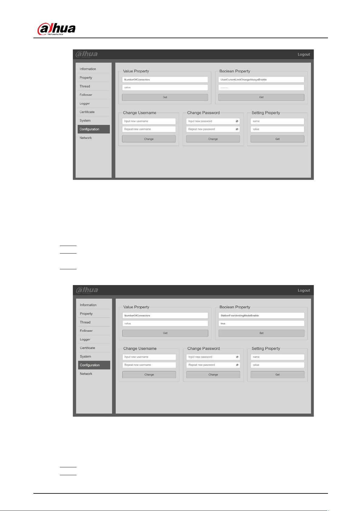
Log in to the webpage, and then select Configuration. Step 1
Modify the login username and password, and then click Change. Step 2
After configuration, restart the EV Charger. Step 3
The settings take effect after restart.
User’s Manual
13
Configuration Figure 4-2
4.1.3 Changing Charging Mode
The EV Charger is set to RFID control and app control by default. You can charge the vehicle by
swiping RFID card or through the app. If you need to change to the free vending (plug & play)
charging mode (in this mode, you can plug the in-body holster in the vehicle for charging), refer to
the following operations.
Log in to the webpage, and then select Configuration. Step 1
In the Boolean Property section, select StationFreeVendingModeEnable and true, and Step 2
then click Set.
After configuration, restart the EV Charger. Step 3
The settings take effect after restart.
Change charging mode Figure 4-3
4.1.4 Modifying Time
When the EV Charger is connected to network, you can modify the time if it is different from the local
time.
Log in to the webpage, and then select Configuration. Step 1
In the Value Property section, select LocationTimezone. Step 2
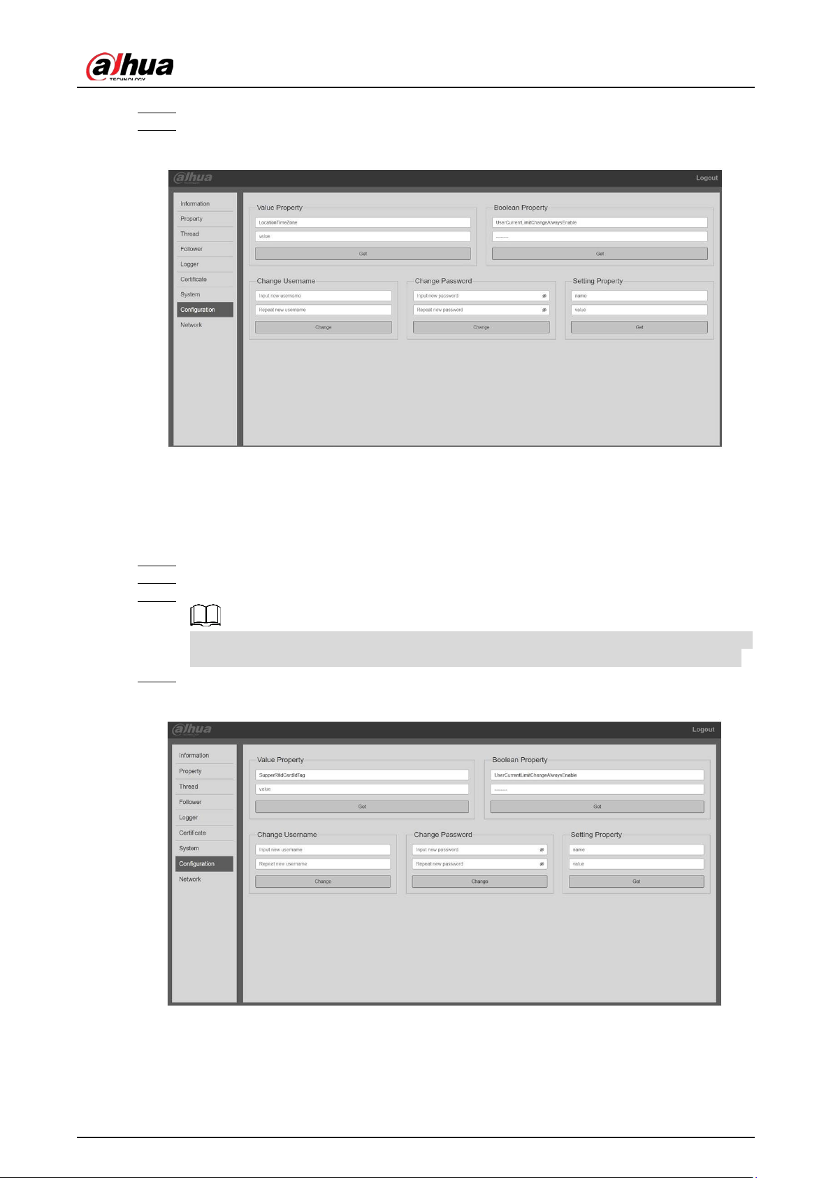
User’s Manual
14
Enter the local time zone in value, and then click Set. Step 3
After configuration, restart the EV Charger. Step 4
The settings take effect after restart.
Modify time Figure 4-4
4.1.5 Configuring a New RFID Card
You can configure a new RFID card if the RFID card comes with the EV Charger is lost, or you need a
new card.
Log in to the webpage, and then select Configuration. Step 1
In the Value Property section, select SupperRfidCardIdTag. Step 2
Enter the RFID card number in value, and then click Set. Step 3
If more than one RFID card is added, separate the card number by |. An EV Charger that is
not connected to the OCPP (Open Charge Point Protocol) system can add 28 cards at most.
After configuration, restart the EV Charger. Step 4
The settings take effect after restart.
Configure new RFID card Figure 4-5
User’s Manual
15
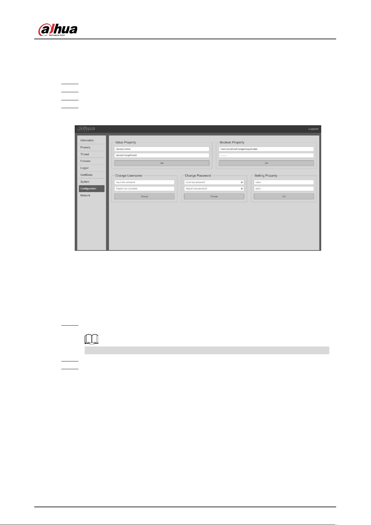
4.1.6 Changing the QR Code on the Screen
The screen shows the ID number of the EV Charger by default. You can change the content on the
screen to the QR code by referring to the following operations.
Log in to the webpage, and then select Configuration. Step 1
In the Value Property section, select QrcodeContext. Step 2
Enter the QR code settings, and then click Set. Step 3
After configuration, restart the EV Charger. Step 4
The settings take effect after restart.
Change the QR code on the screen Figure 4-6
4.1.7 Upgrading the Program
Prerequisites
Obtain the upgrade program from the sales personnel.
Procedure
After powering on the EV Charger, connect its USB port to the computer. Step 1
A new hard drive is displayed on your computer.
For the 7 kW EV Charger, open the left-side cover plate, and then you will see the USB port.
Double-click the hard drive, and then copy the upgrade program file to the firmware folder. Step 2
Unplug the USB cable, restart the EV Charger. Step 3
The upgrade is complete.
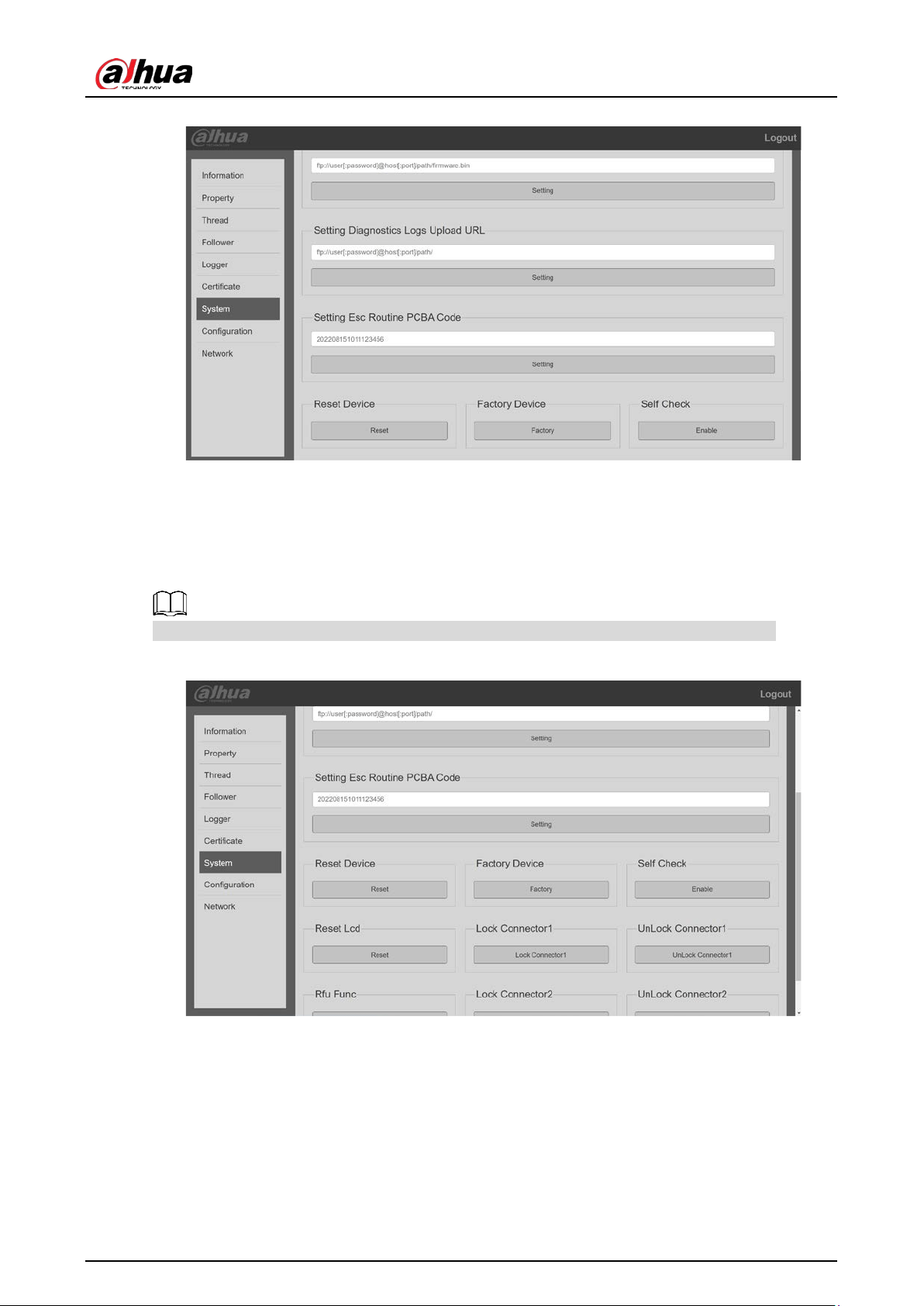
4.1.8 Restarting the EV Charger
To restart the EV Charger, you can:
Log in to the webpage, select System, and then click Reset.
Power off the EV Charger, and then power on it. The EV Charger restarts.
User’s Manual
16
Restart the EV Charger on webpage Figure 4-7
4.1.9 Restoring Factory Default
To restore factory settings and reset parameters, you can:
Press and hold the KEY button of the EV Charger for 10 seconds. After you hear 2 beeps, the
setting is complete.
For the 7 kW EV charger, open the left-side cover plate, and then you will see the KEY button.
Log in to the webpage, select System, and then click Factory.
Restore the EV Charger to factory default Figure 4-8
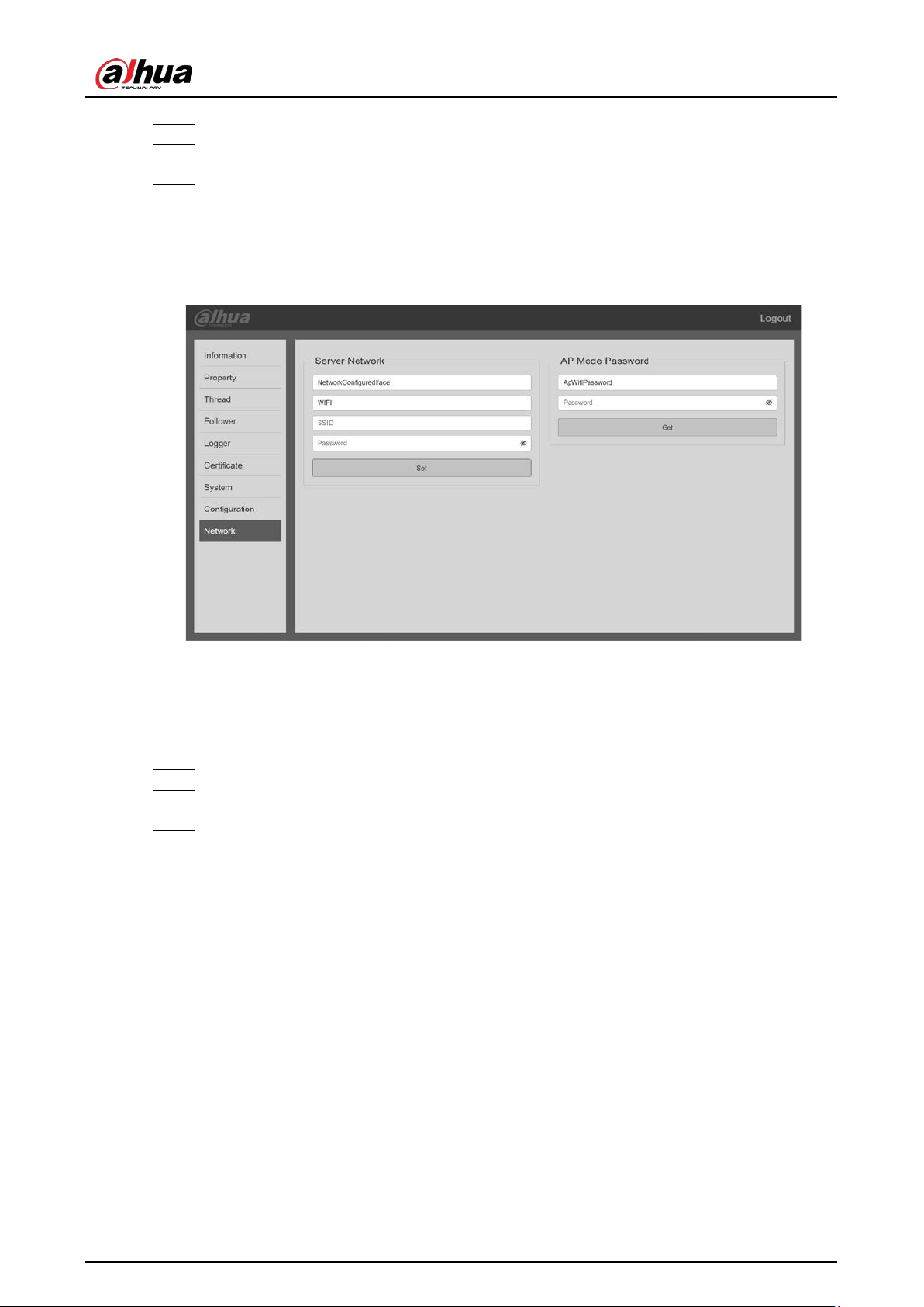
4.1.10 Changing the Network Mode of the EV Charger
The EV Charger supports AP (default) and STA network modes.
AP mode is recommended when external network is not available. To change to AP mode, press
and hold the KEY button of the EV Charger for 5 seconds, when you hear 2 beeps, the EV
Charger restarts, and the configuration is complete.
STA mode can be selected in a network environment with a router. You can change the network
mode to STA mode by referring to the following operations.
User’s Manual
17
Refer to "4.1.1 Logging in to the Webpage" to log in to the webpage. Step 1
In the Server Network section, select NetworkConfiguredlface, set WiFi, enter the Step 2
password of the Wi-Fi account, and then click Set.
After configuration, restart the EV Charger. The settings take effect after restart. Step 3
If you connect the EV Charger and the computer through network cable:
When you restart the EV Charger by logging in to the webpage, selecting System, and
then clicking Reset, unplug the network cable immediately.
When you restart the EV Charger by powering off the EV Charger, unplug the network
cable first, and then power the EV Charger on.
Change the network mode Figure 4-9
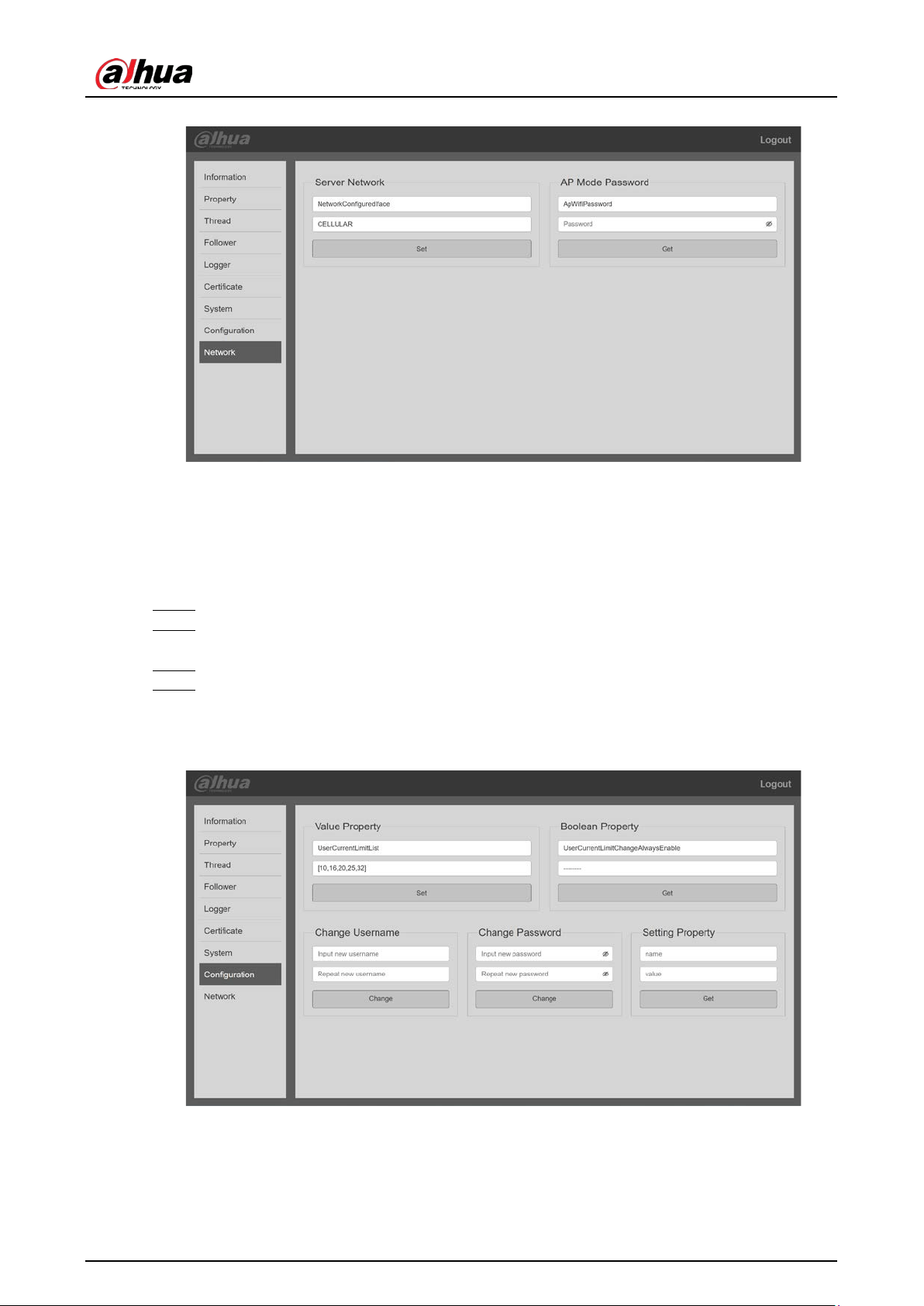
4.1.11 Connecting to Management Platform through 4G
4G is recommended when you need to connect the EV Charger to the management platform, and no
external network is available.
Log in to the webpage, select Network. Step 1
In the Server Network section, select NetworkConfiguredlface, set CELLULAR, and then Step 2
click Set.
After configuration, restart the EV Charger. Step 3
The settings take effect after restart.
If you connect the EV Charger and the computer through network cable:
When you restart the EV Charger by logging in to the webpage, selecting System, and
then clicking Reset, unplug the network cable immediately.
When you restart the EV Charger by powering off the EV Charger, unplug the network
cable first, and then power the EV Charger on.
User’s Manual
18
4G mode Figure 4-10
4.1.12 Adjusting the Charging Current
By default, the EV Charger charges a vehicle at the full load current of 32 A. You can adjust the
charging current on the webpage or through the app. Here introduces the operations on the
webpage.
Log in to the webpage, and then select Configuration. Step 1
In the Value Property section, select UserCurrentLimitList, and then enter the current. Step 2
The current range is 6 A–32 A.
Click Set. Step 3
After configuration, restart the EV Charger. Step 4
The settings take effect after restart.
Before charging a vehicle, or during the charging process, you can adjust the charging
current through the app.
Adjust the charging current Figure 4-11
User’s Manual
19
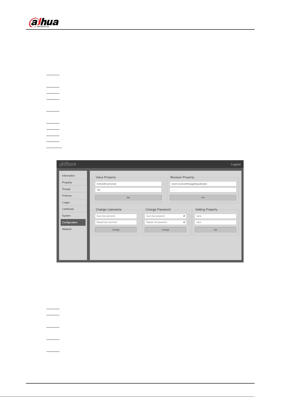
4.1.13 Using Current Transformer
For home EV chargers, when the residual power of the other appliances in the circuit is higher than
the maximum power of the EV charger, the EV Charger can be charged at the maximum power.
Otherwise, you need to adjust the working current of the EV Charger. For details, see the following
operations.
Install the current transformer on all remaining circuit loops in the total input line or output Step 1
line except the EV Charger circuit.
Log in to the webpage, and then select Configuration. Step 2
In the Value Property section, select CurrentSensorCT1Type. Step 3
Select GRID if the current transformer is installed in the input line, or MONITOR if the Step 4
current transformer is installed in the output line.
Lead the signal cable of the current transformer to the CT interface on the EV Charger. Step 5
For the 7 kW EV Charger, the CT interface is on the back of the device.
Log in to the webpage, and then select Configuration. Step 6
In the Value Property section, select GridLimitFuseCurrent. Step 7
Enter the maximum load current of the total circuit loop in value. Step 8
Click Set. Step 9
After configuration, restart the EV Charger. Step 10
The settings take effect after restart.
Use current transformer Figure 4-12
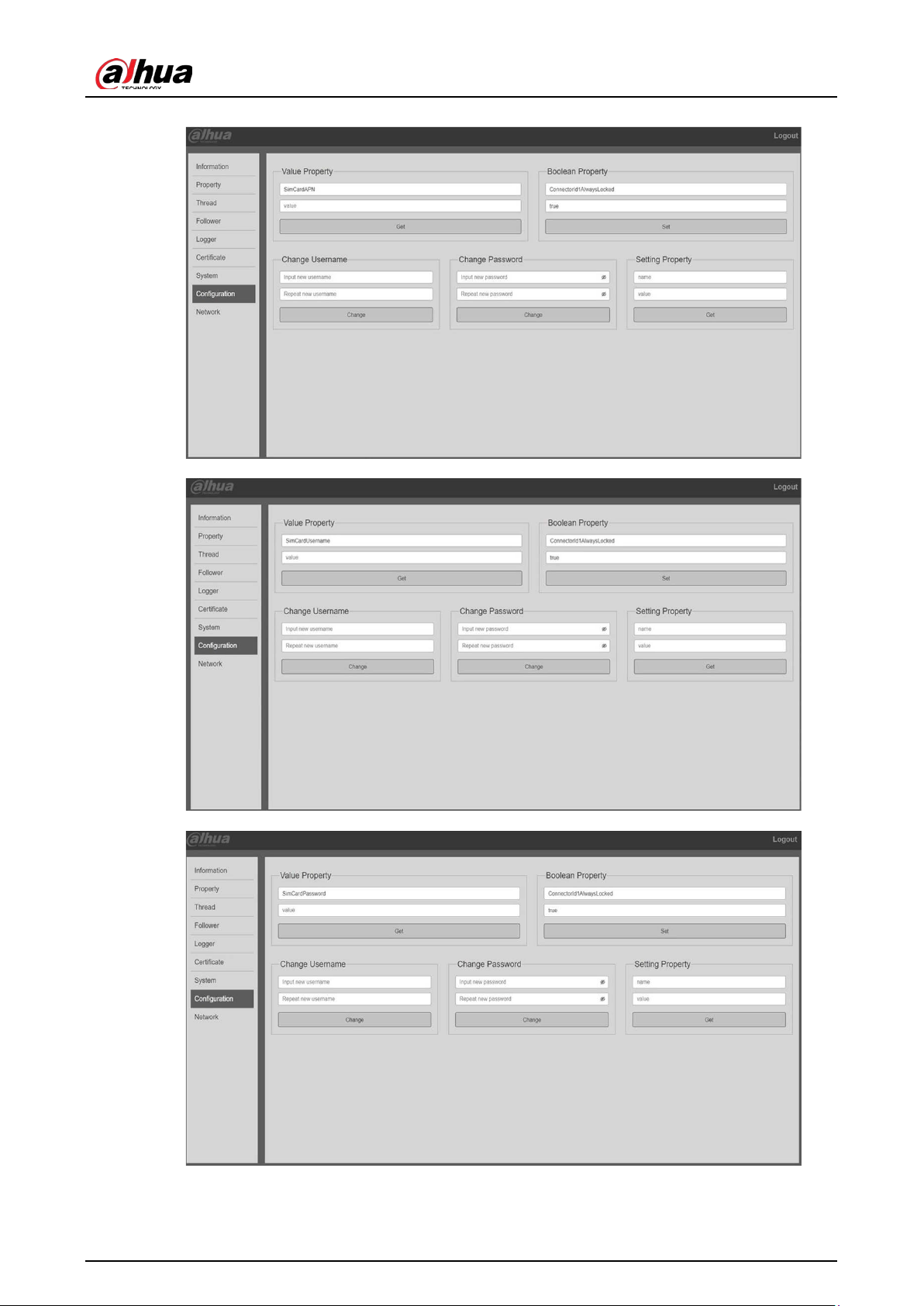
4.1.14 Configuring APN of SIM Card
Most SIM cards use standard access point name (APN), and you do not have to modify the settings.
If the SIM card supplier or the sales personnel specify the APN settings, you can modify the settings
on the webpage according to the following operations.
Log in to the webpage, and then select Configuration. Step 1
In the Value Property section, select SimCardAPN, enter APN access mode in value, and Step 2
then click Set.
In the Value Property section, select SimCardUsername, enter APN username in value, Step 3
and then click Set.
In the Value Property section, select SimCardPassword, enter APN password in value, and Step 4
then click Set.
After configuration, restart the EV Charger. Step 5
The settings take effect after restart.
User’s Manual
20
Enter APN access mode Figure 4-13
Enter APN username Figure 4-14
Enter APN password Figure 4-15
User’s Manual
21
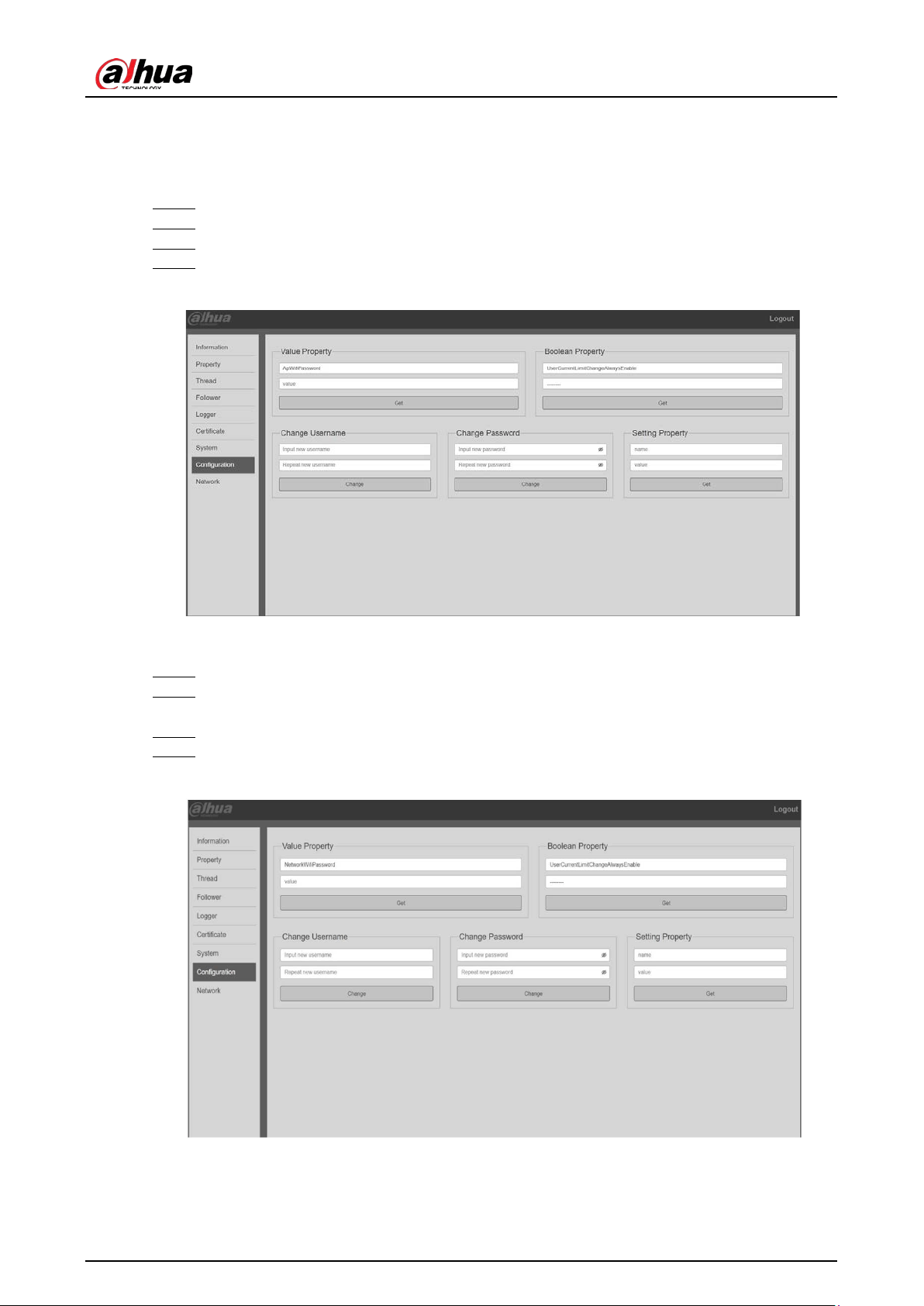
4.1.15 Changing Wi-Fi Password
In access point (AP) mode, you can reset the Wi-Fi password through the app. To change the Wi-Fi
password again, perform the following operations.
Log in to the webpage, select Configuration. Step 1
In the Value Property section, select ApWifiPassword, enter the new password in value. Step 2
Click Set. Step 3
After configuration, restart the EV Charger. Step 4
The settings take effect after restart.
Change Wi-Fi password (AP mode) Figure 4-16
In station (STA) mode, if you need to change the Wi-Fi password again, perform the following
operations.
Log in to the webpage, select Configuration. Step 1
In the Value Property section, select NetworkWifiPassword, enter the new password in Step 2
value.
Click Set. Step 3
After configuration, restart the EV Charger. Step 4
The settings take effect after restart.
Change Wi-Fi password (STA mode) Figure 4-17
User’s Manual
22
Charging the Vehicle 4.2
Park the electric vehicle in place, power off the vehicle, and put the vehicle in braking status. Step 1
Charge the vehicle. You can charge the vehicle in 3 ways. Step 2
Free vending (plug & play): Connect the type 2 tethered cable of the EV Charger to the
charging port of the vehicle. The EV Charger starts charging the vehicle.
Connect EV Charger to the charging port of the vehicle Figure 4-18
RFID control: Swipe the RFID card on the RFID reader of the EV Charger to charge the
vehicle.
App control: Scan the app QR code in the device package, and then you can download
and install the app. Follow the instructions on the app to bind the EV Charger, and
confirm start charging the vehicle on the app.
Stopping Charging 4.3
Normally Stopping Charging
The EV Charger will automatically stop charging the vehicle when the electric vehicle is fully charged.
You can also stop charging the vehicle in one of the following 3 ways:
Press the stop charging button on the electric vehicle (only if the vehicle supports this function).
If the charging does not stop, try to unplug the charging connector directly.
If you start charging by swiping RFID card, swipe again to stop charging the vehicle.
If you start charging through the app, tap the stop icon on the app to stop charging.
After stopping charging, unplug the charging connector, and plug it in the socket of the EV Charger.
Abnormally Stopping Charging
Forced fault stop: A fault stop caused by the charger of the vehicle.
Automatic fault stop: A fault stop caused by the EV Charger.
If charging stops abnormally, refer to "5 Troubleshooting" for troubleshooting, or contact
maintenance service personnel.

User’s Manual
23
5 Troubleshooting
The EV Charger is automatically protected in case of fault. General faults and the solutions are as
follows.
Table 5-1 Faults and solutions
Fault LCD Screen Message Solution
LCD screen is
off
None
Check whether the power supply and
distribution are normal.
Check whether the branch breaker is tripped.
Close the breaker after troubleshooting.
Check whether the connection is correct. If the
cable comes off, properly connect the cable.
CP failure
EV Communication
Error
Check whether the adapter is properly connected to
the electric vehicle. Pull and plug the adapter and try
charging again.
Emergency
stop
E-stop
Check whether the EV Charger is working properly,
and rotate the emergency button.
Undervoltage
fault
Under Voltage
Check whether the input cable is reliably
connected.
Check whether the parent grid is properly
connected.
Check whether the grid voltage is abnormal.
Overvoltage
fault
Over Voltage
Check whether the input cable is connected
correctly.
Check whether the grid voltage is abnormal.
Overtemperat
ure fault
High Temperature
Check whether the EV Charger is covered or installed
in a high-temperature environment.
Meter failure Power Meter Failure Power off, and then restart the device.
Leakage fault LeakageRcmuError
Check whether the charging adapter and its cable are
damaged or wet. Recover after pulling out the
adapter.
Overcurrent
fault
Over Current Failure
Check whether the charging adapter is correctly
connected to the vehicle.
Check whether the charger on the vehicle is
normal.
Vehicle has no
diode
EV Communication
Error
The vehicle does not conform to standards, and
cannot be charged.
Relay sticking
fault
Power Switch Failure
The device is damaged, and needs to be returned to
the factory for repair.
Ground fault Ground Failure
The EV Charger is not grounded, so the circuit needs
to be tested.

User’s Manual
24
Abbreviations Appendix 1
No. Abbreviation Description
1
IEC
International electrotechnical commission.
2 EV Electrical vehicle. This can be battery EV (BEV) or plug-in hybrid EV (PHEV).
3
EVSE
Electric vehicle supply equipment [IEC61851-1].
4
kW
Kilo watts. Unit of power.
5
A
Ampere. Unit of current.
6
V
Volt. Unit of voltage.
7
Hz
Hertz. Unit of frequency.
8
LCD
Liquid crystal display.
9
RFID
Radio frequency identification.
10 CMS
Central management system. Manages EVSE and has the information for
authorizing users for using its EVSE.
11 OCPP
Open charge point protocol. A standard open protocol for
communication between EVSE and a central system, and is designed to
accommodate any type of charging technique.
(www.openchargealliance.org)
12
IP
Ingress protection.
13
PE
Protective earthing.
14
HMI
Human-machine interface.
15
RCMU
Residual current monitoring unit.
16
MCB
Miniature circuit breaker.
17
OBC
On-board charger (of an EV).
18
RoHS
Restriction of hazardous substances.
19
REACH
Registration, evaluation and authorization of chemicals.

User’s Manual
25
Cybersecurity Recommendations Appendix 2
Cybersecurity is more than just a buzzword: it’s something that pertains to every device that is
connected to the internet. IP video surveillance is not immune to cyber risks, but taking basic steps
toward protecting and strengthening networks and networked appliances will make them less
susceptible to attacks. Below are some tips and recommendations from Dahua on how to create a
more secured security system.
Mandatory actions to be taken for basic device network security:
1. Use Strong Passwords
Please refer to the following suggestions to set passwords.
The length should not be less than 8 characters.
Include at least two types of characters; character types include upper and lower case
letters, numbers and symbols.
Do not contain the account name or the account name in reverse order.
Do not use continuous characters, such as 123, abc, etc.
Do not use overlapped characters, such as 111, aaa, etc.
2. Update Firmware and Client Software in Time
According to the standard procedure in Tech-industry, we recommend to keep your device
(such as NVR, DVR, IP camera, etc.) firmware up-to-date to ensure the system is equipped
with the latest security patches and fixes. When the device is connected to the public
network, it is recommended to enable the “auto-check for updates” function to obtain
timely information of firmware updates released by the manufacturer.
We suggest that you download and use the latest version of client software.
"Nice to have" recommendations to improve your device network security:
1. Physical Protection
We suggest that you perform physical protection to device, especially storage devices. For
example, place the device in a special computer room and cabinet, and implement well-done
access control permission and key management to prevent unauthorized personnel from
carrying out physical contacts such as damaging hardware, unauthorized connection of
removable device (such as USB flash disk, serial port), etc.
2. Change Passwords Regularly
We suggest that you change passwords regularly to reduce the risk of being guessed or cracked.
3. Set and Update Passwords Reset Information Timely
The device supports password reset function. Please set up related information for password
reset in time, including the end user’s mailbox and password protection questions. If the
information changes, please modify it in time. When setting password protection questions, it is
suggested not to use those that can be easily guessed.
4. Enable Account Lock
The account lock feature is enabled by default, and we recommend you to keep it on to
guarantee the account security. If an attacker attempts to log in with the wrong password
several times, the corresponding account and the source IP address will be locked.
5. Change Default HTTP and Other Service Ports
We suggest you to change default HTTP and other service ports into any set of numbers
between 1024–65535, reducing the risk of outsiders being able to guess which ports you are
using.
6. Enable HTTPS
We suggest you to enable HTTPS, so that you visit Web service through a secure communication
channel.
7. MAC Address Binding
We recommend you to bind the IP and MAC address of the gateway to the device, thus reducing
the risk of ARP spoofing.
8. Assign Accounts and Privileges Reasonably

User’s Manual
26
According to business and management requirements, reasonably add users and assign a
minimum set of permissions to them.
9. Disable Unnecessary Services and Choose Secure Modes
If not needed, it is recommended to turn off some services such as SNMP, SMTP, UPnP, etc., to
reduce risks.
If necessary, it is highly recommended that you use safe modes, including but not limited to the
following services:
SNMP: Choose SNMP v3, and set up strong encryption passwords and authentication
passwords.
SMTP: Choose TLS to access mailbox server.
FTP: Choose SFTP, and set up strong passwords.
AP hotspot: Choose WPA2-PSK encryption mode, and set up strong passwords.
10. Audio and Video Encrypted Transmission
If your audio and video data contents are very important or sensitive, we recommend that you
use encrypted transmission function, to reduce the risk of audio and video data being stolen
during transmission.
Reminder: encrypted transmission will cause some loss in transmission efficiency.
11. Secure Auditing
Check online users: we suggest that you check online users regularly to see if the device is
logged in without authorization.
Check device log: By viewing the logs, you can know the IP addresses that were used to log
in to your devices and their key operations.
12. Network Log
Due to the limited storage capacity of the device, the stored log is limited. If you need to save
the log for a long time, it is recommended that you enable the network log function to ensure
that the critical logs are synchronized to the network log server for tracing.
13. Construct a Safe Network Environment
In order to better ensure the safety of device and reduce potential cyber risks, we recommend:
Disable the port mapping function of the router to avoid direct access to the intranet
devices from external network.
The network should be partitioned and isolated according to the actual network needs. If
there are no communication requirements between two sub networks, it is suggested to
use VLAN, network GAP and other technologies to partition the network, so as to achieve
the network isolation effect.
Establish the 802.1x access authentication system to reduce the risk of unauthorized access
to private networks.
Enable IP/MAC address filtering function to limit the range of hosts allowed to access the
device.
More information
Please visit Dahua official website security emergency response center for security announcements
and the latest security recommendations.

User’s Manual