SAVE THESE INSTRUCTIONS FOR FUTURE REFERENCE.
4
Connecting the Water line (washer)
1. Place a level on top of the laundry center with the
unit within 3 ft (1m) of the final location.
2. Use an adjustable wrench to adjust the leveling
legs so the unit is level front-to-rear and
side-to-side, and stable corner-to-corner.
3. Press down on alternate corners and sides and feel
for the slightest movement. Adjust the appropriate
leg(s) so the unit sits solidly on the floor on ALL four
legs. Keep the leveling leg extension at a minimum
for best performance of the laundry center.
1. Plug both power cords into grounded outlets.
2. Turn on the power at a circuit breaker/fuse box. Carefully slide the laundry center to its final position.
Recheck leveling and rock corners for stability. See “2 Leveling the Laundry Center”. Remove and
discard any tape on doors.
3. Run the washer through a complete cycle, checking for water leaks and proper operation.
4. Run the dryer for a few minutes to check for proper operation.
5. If you have any questions during initial operation, please review the troubleshooting section in the Use
& Care manual before calling for service.
3
2
Leveling the Laundry Center
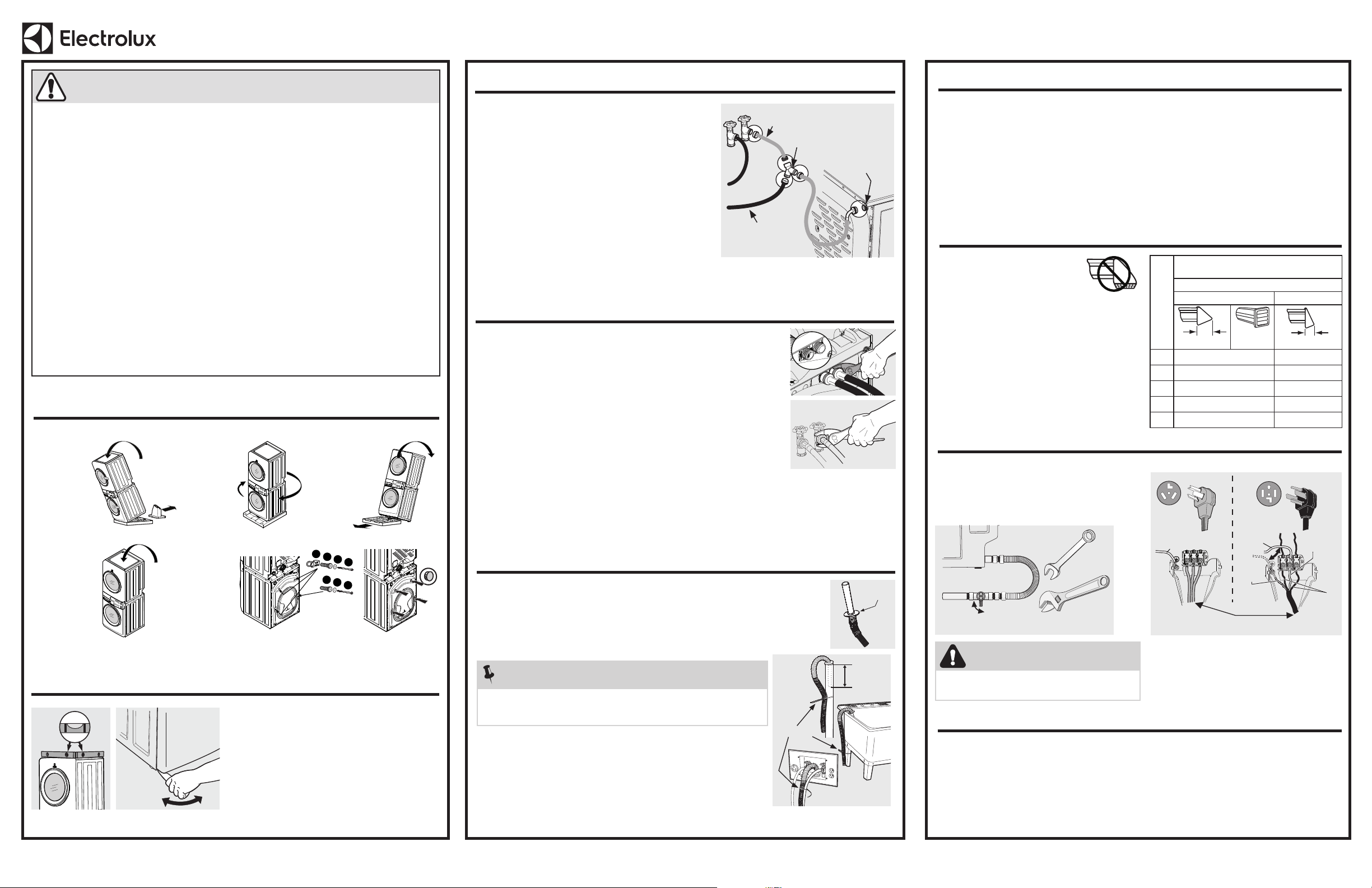
Connecting Water Line (steam dryer models only)
If this is not a steam model, skip to section 4
1. Inspect all hoses for rubber washers prior to use.
2. Run water from cold outlet to clear contaminants.
3. Connect the dryer Assembly Hose Kit hose extensions
from the cold supply to the “Y” connector, then from the
“Y” connector to the water inlet on the dryer.
4. Attach the washer cold water supply line to the “Y”
connector.
5. Tighten all connections by hand, then tighten additional
2/3 turn with pliers.
6. Turn on water and check for leaks.
Short Hose
Water Inlet
(steam)
Cold Water Supply
Hose to Washer
“Y” Connector
Assembly Hose Kit P/N 5304495002 is not included with
purchase of steam model and MUST be
purchased separately.
A25903101 (2303)
For support in the U.S. call 1-877-4ELECTROLUX (1-877-435-3287) or visit www.electroluxappliances.com. For support in Canada call 1-800-265-8352 or visit www.electroluxappliances.ca.
TO INSTALLER:
Leave these instructions with the customer.
*Please refer to the Use & Care manual provided with this appliance for further details.
Installation* for Electrolux Laundry Center
1
Removing Foam Packaging and Shipping Hardware
WARNING - RISK OF FIRE
Read all the following instructions before installing and using this appliance.
• The installation and service of this Laundry Center must be performed by a qualified installer, service
agency or the gas supplier.
• THIS EQUIPMENT HAS TWO CONNECTIONS TO THE POWER SUPPLY. DISCONNECT BOTH
POWER SUPPLY CONNECTIONS BEFORE SERVICING. Each appliance shall be connected to an
individual branch circuit only. The washer and dryer must be on separate circuits.
• DO NOT install a clothes dryer with flexible plastic or flexible foil venting material. Flexible venting
materials are known to collapse, be easily crushed and trap lint. These conditions will obstruct clothes
dryer airflow and increase the risk of fire.
• Ensure the entire dryer exhaust system is clean and free of lint and debris prior to the installation of your new
Laundry Center. The entire exhaust system should be inspected and cleaned a minimum of every 18 months
with normal usage. Failure to comply with cleaning your exhaust system will increase the RISK of FIRE.
• For your safety the information in this manual must be followed to minimize the risk of fire or explosion
or to prevent property damage, personal injury or loss of life. Do not store or use gasoline or other
flammable vapors and liquids in the vicinity of this or any other appliance.
• Install the appliance according to the manufacturer’s instructions and local codes.
• The electrical service to the appliance must conform with local codes and ordinances and the latest edition of
the National Electrical Code, ANSI/NFPA 70, or in Canada, the Canadian Electrical Code CSA C22.1 part 1.
• To avoid back or other injury, have more than one person move or lift the appliance.
• Do not stack this appliance on a pedestal.
• Turn off power at the circuit breaker or fuse box before installation.
The instructions in this manual and all other literature included with this appliance are not meant to cover
every possible condition and situation that may occur. Good safe practice and caution MUST be applied
when installing, operating and maintaining any appliance.
4
3
2
1
4
3
2
Tape doors closed. Do not allow the unit to fall.
1. Carefully tilt
forward.
5. Tilt backward
and remove
pad.
6. Return unit
upright.
7. Remove
and save
the shipping
bolts.
8. Insert hole
plugs (in
bag).
3. Return unit
upright.
• Skip steps 1 and 2 below if this model has a
steam dryer.
• Inlet hoses are not included and MUST be
purchased separately.
1. Run some water from the hot and cold faucets
to flush the water lines and remove particles
that might clog the water valve screens and
to determine which faucet is hot and which is
cold supply.
2. Check to ensure that the inlet hoses have the
rubber washer firmly in place.
3. Connect the HOT hose to the RED connection
on the washer and the COLD hose to the
BLUE connection on the washer. Tighten by
hand until snug. Then tighten each supply
connection another 2/3 turn with pliers. Do
not cross thread or over-tighten these
connections.
For detailed information, refer to "Connecting the Water (Steam Models Only)" in the
Installation sections of the Use & Care manual provided with this laundry center.
For detailed information, refer to "Connecting the Water" in the Installation sections of
the Use & Care manual provided with this laundry center.
4. Connect the HOT inlet
hose to the HOT water
supply and the COLD
inlet hose to the COLD
water supply, or to the
“Y” connector (section 3)
if this is a steam model.
5. Tighten by hand until
snug. Then tighten
each supply connection
another
2/3 turn with pliers.
Do not bend, kink
or pinch water inlet
hoses.
6. Turn on the water and check for leaks.
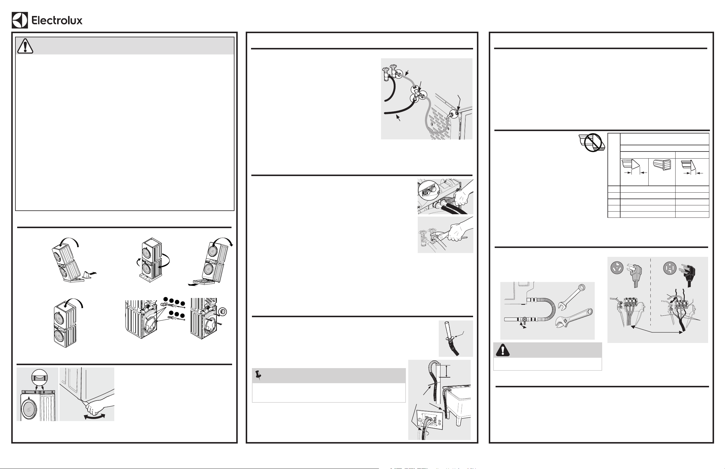
Exhaust system must be
vented outside with approved
vent hood. No screen or grate
of any mesh size is allowed
to cover the exhaust opening.
• Use only 4 inch rigid or semi-rigid metal ducting.
• Clean lint from duct system.
• Use only metal foil tape to connect ducts (no screws).
• Use 4" (10.2 cm) clamp to connect dryer & exhaust
system.
• Use 90° quick-turn elbow to vent left or right from
dryer. Never exceed more than 4 - 90˚ elbows in
the exhaust duct system.
MAX Number of 90°
turns
MAXIMUM LENGTH*
of 4” (10.2 cm) Rigid Metal Duct
VENT HOOD TYPE
(Preferred)
4” (10.2 cm)
louvered
2.5” (6.35 cm)
0 125 ft. (38 m) 110 ft. (33.5 m)
1 115 ft. (35 m) 100 ft. (30.5 m)
2 105 ft. (32 m) 90 ft. (27.5 m)
3 95 ft. (29 m) 80 ft. (24.5 m)
4 85 ft. (26 m) 70 ft. (21.5 m)
7
Connecting or Constructing Vent Exhaust (Dryer)
See Clearance Requirements in the Pre-Installation
sections of the Use & Care manual provided with this
laundry center.
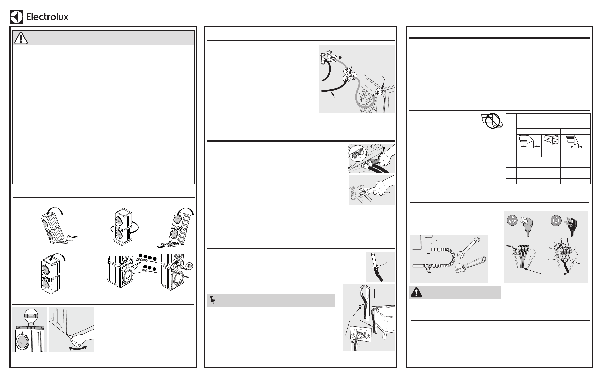
Electric Dryer
Don’t Move
White Wire
Move
White Wire
White
Wire
Green
Wire
Black
or
Red
Wire
Install
U.L.-Approved Strain Relief
30 AMP 30 AMP
8
Connecting to Gas or Electric (Dryer)
Gas Dryer
1. Apply approved thread sealant.
2. Wrench-tighten gas line.
3. Open gas valve and check for leaks with soapy
water.
Open
Close
Manual Shutoff
For detailed information, refer to the
Installation sections of the Use & Care
manual
provided with this laundry
center.
5
6
Connecting the Drain (Washer)
Electrical Requirements
1. Verify the anti-siphon disc is in place.
2. Form a “U” shape on the end of the drain hose with the hose pointed toward the drain.
Place the formed end in a laundry tub or a standpipe and secure the drain hose with
the cable tie (provided in the enclosure package) to the standpipe, inlet hose, laundry
tub, etc. so the hose does not pull out from the force of the water.
3. Run the washer through a complete cycle, checking for water leaks and proper
operation.
Electric Dryer
1. CIRCUIT - Individual 30A branch circuit fused with 30A time delay fuses or circuit breakers.
2. POWER SUPPLY - 3-wire or 4-wire, 240V, single phase, 60Hz, AC. The power cord is NOT supplied with unit.
3. OUTLET RECEPTACLE - NEMA 10-30R or NEMA 14-30R receptacle to be located so the power
supply cord is accessible when the dryer is in the installed position.
Gas Dryer and Washer
1. CIRCUIT - Individual, properly polarized and grounded 15A branch circuit fused with 15A time delay
fuse or circuit breaker.
2. POWER SUPPLY - 2 wire, with ground, 120V single phase, 60Hz, AC.
3. OUTLET RECEPTACLE - Properly grounded 3-prong receptacle to be located so the power supply
cord is accessible when the washer is in an installed position.
Anti-Siphon
Disc
Insert Less
Than 8.5"
(21.5 cm)
Cable Tie
For detailed information, refer to "Connecting the Drain" in
the Installation sections of the Use & Care manual provided
with this laundry center.
9
Completing the Installation
NOTE
The standpipe inside diameter must be 1-1/4” (3.2 cm) minimum. There
must be an air gap around the drain hose in the standpipe. A snug hose fit
can cause a siphoning action.
DANGER
If using LP (Liquid Propane) STOP and install the
LP kit before operating your gas dryer.
2. Remove
plug.
4. Twist and
slide unit to
rear of pad.
CONSERVEZ CES INSTRUCTIONS POUR CONSULTATION ULTÉRIEURE.
4
Raccordement de la conduite d’eau (laveuse)
1. Placez un niveau sur le dessus de l’ensemble laveuse/
sécheuse avec l’appareil à moins de 3pi (1m) de
l’emplacement final.
2. Utilisez une clé à molette pour régler les pieds de
nivellement de manière à ce que l’appareil soit au
niveau à l’avant comme à l’arrière et des deux côtés,
et que tous les coins soient stables.
3. Appuyez sur les coins et les côtés les uns après les
autres pour détecter le moindre mouvement. Réglez
le(s) pied(s) concerné(s) de manière à ce que les
QUATRE pieds de l’appareil reposent solidement
sur le sol. Gardez les pieds de nivellement le plus
bas possible de manière à obtenir les meilleures
performances de l’ensemble laveuse/sécheuse.
1. Branchez les deux cordons d’alimentation dans des prises mises à la terre.
2. Branchez les cordons d’alimentation dans des prises avec mise à la terre.
3. Mettez le disjoncteur/la boîte à fusibles sous tension. Faites glisser délicatement l’ensemble laveuse/sécheuse
jusqu’à ce qu’il atteigne sa position finale. Vérifiez de nouveau qu’elle est à niveau et stable en appuyant sur les
coins. Voir «2Mise au niveau de l’ensemble laveuse/sécheuse». Retirez et jetez tout ruban adhésif sur les portes.
4. Faites fonctionner la laveuse pendant un cycle complet, en vérifiant l’absence de fuite d’eau et son bon
fonctionnement.
5. Faites fonctionner la sécheuse pendant quelques minutes pour vérifier son bon fonctionnement.
6. Si vous avez des questions pendant le fonctionnement initial, veuillez consulter la section «Dépannage» du manuel
d’utilisation et d’entretien avant de faire appel au service après-vente.
3
2
Mise au niveau de l’ensemble laveuse/sécheuse
Raccordement de l’eau (modèles de sécheuses à vapeur seulement)
S’il ne s’agit pas d’un modèle à vapeur, passez à la section4
1. Inspectez tous les tuyaux pour déceler la présence de
rondelles en caoutchouc avant de les utiliser.
2. Faites couler l’eau de la sortie du froid pour éliminer les
contaminants.
3. Raccordez les rallonges de tuyau de la trousse de tuyau
d’assemblage de la sécheuse depuis l’alimentation en eau
froide jusqu’au connecteur en «Y», puis depuis le connec-
teur en «Y» jusqu’à l’entrée d’eau de la sécheuse.
4. Fixez la conduite d’alimentation en eau froide de la laveuse
au connecteur en «Y».
5. Serrer toutes les connexions à la main, puis serrer de 2/3
de tour supplémentaire avec une pince.
6. Ouvrez l’eau et vérifiez l’absence de fuite.
Tuyau court
Entrée d’eau
(vapeur)
Tuyau d’alimentation
en eau froide
de la laveuse.
Connecteur
en « Y »
La trousse de tuyau d’assemblage N/P 5304495002 n’est
pas incluse avec l’achat d’un modèle à vapeur et DOIT être
achetée séparément.
A25903101 (2303)
Pour obtenir de l’aide aux États-Unis, composez le 18774ELECTROLUX (1877435-3287) ou visitez www.electroluxappliances.com. Pour obtenir de l’aide au Canada, composez le 1800265-8352 ou visitez www.electroluxappliances.ca.
ÀL’INSTALLATEUR:
Laissez ces instructions auclient.
*Veuillez consulter le manuel d’utilisation et d’entretien fourni avec cet appareil pour plus dedétails.
Installation* de l’ensemble laveuse/sécheuse Electrolux
1
Retrait du matériel d’emballage en mousse et d’expédition
AVERTISSEMENT – RISQUE D’INCENDIE
Lisez toutes les instructions suivantes avant d’installer et d’utiliser cet appareil.
• L’installation et l’entretien de ce centre de buanderie doivent être effectués par un installateur qualifié, une
agence de service ou le fournisseur de gaz.
• CET ÉQUIPEMENT A DEUX CONNEXIONS À L’ALIMENTATION ÉLECTRIQUE. DÉBRANCHEZ LES
DEUX CONNEXIONS D’ALIMENTATION ÉLECTRIQUE AVANT L’ENTRETIEN. Chaque appareil doit être
connecté à un circuit de dérivation individuel uniquement. La laveuse et la sécheuse doivent être sur des
circuits séparés.
• N’INSTALLEZ PAS une sécheuse avec un matériau de ventilation en plastique souple ou en feuille
d’aluminium souple. Les matériaux de ventilation flexibles sont connus pour s’affaisser, être facilement
écrasés et emprisonner les peluches. Ces conditions obstrueront le débit d’air de la sécheuse et
augmenteront le risque d’incendie.
• Assurez-vous que tout le système d’évacuation de la sécheuse est propre et exempt de peluches et de
débris avant l’installation de votre nouveau centre de buanderie. L’ensemble du système d’échappement
doit être inspecté et nettoyé au moins tous les 18 mois dans le cadre d’une utilisation normale. Le non-
respect du nettoyage de votre système d’échappement augmentera le RISQUE d’INCENDIE.
• Pour votre sécurité, les informations contenues dans ce manuel doivent être suivies afin de limiter les
risques d’incendie ou d’explosion ou pour éviter tout dommage matériel, toute blessure corporelle ou la
mort. Ne pas entreposer ou utiliser de l’essence ou d’autres vapeurs et liquides inflammables à proximité
de cet appareil ou de tout autre appareil.
• Installez l’appareil conformément aux instructions du fabricant et aux codes locaux.
• L’entretien électrique de l’appareil doit être conforme aux codes et ordonnances locaux et à la dernière édition du
Code national de l’électricité, ANSI/NFPA70, ou, au Canada, au Code canadien de l’électricité, CSAC22.1, partie1.
• Pour éviter les blessures au dos ou d’autres types, veillez à ce qu’au moins deux personnes déplacent ou
soulèvent l’appareil.
• N’empilez pas cet appareil sur un piédestal.
• Coupez l’alimentation du disjoncteur ou de la boîte à fusibles avant l’installation.
Les instructions contenues dans ce manuel et toute la documentation fournie avec cet appareil ne visent
pas à couvrir toutes les conditions et situations possibles qui pourraient se produire. Lors de l’installation, du
fonctionnement et de l’entretien de tout appareil, il FAUT faire preuve de bonnes pratiques et de prudence.
Fermez les portes avec du ruban adhésif. Ne laissez pas l’appareil tomber.
1. Inclinez
soigneusement
vers l’avant.
5. Inclinez-la
vers l’arrière
et retirez la
plaque de
séparation.
6. Remettez
l’appareil à
la verticale.
7. Retirez et
conservez
les boulons
d’expédition.
8. Insérez les
bouchons
pour les trous
(dans le sac).
3. Remettez
l’appareil à
la verticale.
• Ignorez les étapes1 et 2 ci-dessous si cette
sécheuse est un modèle à vapeur.
• Les tuyaux d’entrée ne sont pas inclus et
DOIVENT être achetés séparément.
1. Faites couler l’eau des robinets d’eau
chaude et froide pour rincer les conduites
d’eau et éliminer les particules susceptibles
d’obstruer les crépines du robinet d’eau, et
pour déterminer quels sont les robinets d’eau
chaude et d’eau froide.
2. Assurez-vous que la rondelle en caoutchouc
est bien en place sur les tuyaux d’entrée.
3. Connectez le tuyau CHAUD à la connexion
ROUGE de la laveuse et le tuyau FROID à la
connexion BLEUE de la laveuse. Serrez à la
main jusqu’à ce qu’ils soient bien serrés. Serrez
ensuite chaque raccord d’alimentation de 2/3
de tour à l’aide de pinces. Ne pas visser en
diagonale ni trop serrer ces raccords.
Pour obtenir des renseignements détaillés, reportez-vous à la section «Raccordement
de l’eau (modèles à vapeur seulement)» dans les sections «Installation» du manuel
d’utilisation et d’entretien fourni avec cet ensemble laveuse/sécheuse.
Pour obtenir des renseignements détaillés, reportez-vous à la section «Raccordement
de l’eau» dans les sections «Installation» du manuel d’utilisation et d’entretien fourni
avec cet ensemble laveuse/sécheuse.
4. Branchez le tuyau
d'entrée d'eau CHAUDE
à l'alimentation d'eau
CHAUDE et le tuyau
d'entrée d'eau FROIDE
à l'alimentation d'eau
FROIDE, ou au
connecteur en «Y»
(section3) s'il s'agit d'un
modèle à vapeur.
5. Serrez à la main jusqu’à
ce qu’ils soient bien
serrés. Serrez ensuite
chaque raccord
d’alimentation de 2/3
de tour à l’aide de pinces. Ne pas plier, tordre, ni
pincer les tuyaux d’entrée d’eau.
6. Ouvrez l’eau et vérifiez l’absence de fuite.
Le système d’échappement doit
être ventilé à l’extérieur avec une
hotte d’évacuation approuvée.
Aucune grille ni aucun grillage,
peu importe la taille du maillage,
ne doit recouvrir l’ouverture d’évacuation.
• N’utilisez que des conduits en métal rigides ou
semi-rigides de 4pouces (10,2cm).
• Nettoyer les peluches du système de conduits.
• N’utilisez que du ruban métallique pour connecter
les conduits (pas de vis).
• Utilisez une pince de 4po (10,2cm) pour
connecter la sécheuse et le système
d’échappement.
• Utilisez un coude à rotation rapide de 90° pour
ventiler à gauche ou à droite de la sécheuse.
MAXIMUM
de coudes à90°
LONGUEUR MAXIMALE*
de conduit en métal rigide de 4po (10,2cm)
TYPE DE HOTTE À ÉVACUATION
(préférés)
4po
(10,2cm)
à persiennes
2,5po (6,35cm)
0 125pi (38m) 110pi (33,5m)
1 115pi (35m) 100pi (30,5m)
2 105pi (32m) 90pi (27,5m)
3 95pi (29m) 80pi (24,5m)
4 85pi (26m) 70pi (21,5m)
7
Raccordement ou construction de
l’échappement de ventilation (sécheuse)
Sécheuse électrique
Ne pas déplacer
le fil blanc
Déplacer
le fil blanc
Fil blanc
Fil vert
Fil noir
ou rouge
Installez un réducteur de tension approuvé par l’U.L.
30 A 30 A
8
Raccordement au gaz ou à l’électricité (sécheuse)
Sécheuse à gaz
1. Appliquez un enduit d’étanchéité pour filetage
approuvé.
2. Serrez la conduite de gaz avec une clé.
3. Ouvrez la vanne de gaz et vérifiez s’il y a des fuites
avec de l’eau savonneuse.
Ouvrir
Fermer
Arrêt manuel
5
Raccordement du drain (laveuse)
1. Vérifiez que le disque anti-siphon est en place.
2. Arrangez le tuyau de vidange de manière à former un «U» à son extrémité, avec le
tuyau orienté vers l’évacuation. Placez l’extrémité ainsi formée dans une cuve à lessive
ou un tuyau vertical et fixez le tuyau de vidange à l’aide du serre-câbles (fourni dans
l’emballage du boîtier) au tuyau vertical, au tuyau d’admission, à la cuve à lessive, etc.
afin que le tuyau ne soit pas éjecté par la force de l’eau.
3. Exécutez la laveuse à travers un cycle complet, en vérifiant les fuites d’eau et le bon
fonctionnement.
Disque
anti-siphon
Insérez
à moins
de 8,5 po
(21,5 cm)
Attache
de câble
Pour obtenir des renseignements détaillés, reportez-vous à
la section «Raccordement du conduit de drainage» dans les
sections «Installation» du manuel d’utilisation et d’entretien
fourni avec cet ensemble laveuse/sécheuse.
9
Fin de l’installation
REMARQUE
Le diamètre intérieur du tuyau vertical doit être de 1-1/4po (3,2cm)
minimum. Un vide d’air doit se trouver autour du tuyau de vidange dans le
tuyau vertical. Un tuyau trop serré peut entraîner le siphonnage.
DANGER
Si vous utilisez du propane liquide (PL), ARRÊTEZ et installez
la trousse de PL avant d’utiliser votre sécheuse à gaz.
2. Retirez le
bouchon.
4. Tournez et
faites glisser
l’unité vers
l’arrière de
la plaque de
séparation.
4
3
2
1
4
3
2
Pour des informations détaillées,
reportez-vous aux sections
«Installation» du manuel d'utilisation
et d'entretien fourni avec ce centre de
lavage.
6
Exigences électriques
Sécheuse électrique
1. CIRCUIT - Circuit de dérivation individuel de 30 A avec fusibles temporisés de 30 A ou disjoncteurs.
2. ALIMENTATION - 3 fils ou 4 fils, 240V, monophasé, 60Hz, AC. Le cordon d'alimentation n'est PAS
fourni avec l'appareil.
3. PRISE DE SORTIE - La prise NEMA 10-30R ou NEMA 14-30R doit être située de manière à ce que le
cordon d'alimentation soit accessible lorsque la sécheuse est en position installée.
Sécheuse et laveuse à gaz
1. CIRCUIT - Circuit de dérivation individuel de 15A correctement polarisé et mis à la terre, fusionné
avec un fusible temporisé de 15A ou un disjoncteur.
2. ALIMENTATION ÉLECTRIQUE - 2 fils, avec terre, 120V monophasé, 60Hz, AC.
3. PRISE DE SORTIE - Prise à 3 broches correctement mise à la terre à placer de sorte que le cordon
d'alimentation soit accessible lorsque la laveuse est en position installée.
Voir «Exigences de dégagement dans les sections de
«Pré-installation» du manuel d'utilisation et d'entretien
fourni avec ce centre de lavage.
GUARDE ESTAS INSTRUCCIONES PARA PODER CONSULTARLAS EN EL FUTURO.
4
Conexión de la línea de agua (lavadora)
1. Coloque un nivel en la parte superior del centro de
lavandería con la unidad a menos de 3 pies (1 m) de la
ubicación final.
2. Utilice una llave ajustable para ajustar las patas
niveladoras de modo que esté nivelada de adelante
hacia atrás y de lado a lado, y estable de esquina a
esquina.
3. Presione hacia abajo las esquinas y los lados
alternos y sienta el menor movimiento. Ajuste las
patas apropiadas de manera que quede firmemente
apoyada en el piso en las CUATRO patas. Mantenga
la extensión de la pata de nivelación al mínimo para un
mejor rendimiento del centro de lavandería.
1. Enchufe ambos cables de alimentación en tomas de corriente con conexión a tierra.
2. Conecte los cables de alimentación a un tomacorriente con conexiones a tierra.
3. Encienda la alimentación en un disyuntor/caja de fusibles. Deslice con cuidado el centro de lavandería
hasta su posición final. Vuelva a verificar la estabilidad de las esquinas niveladas. Consulte “2
Nivelación del centro de lavandería”. Retire y deseche cualquier cinta adhesiva de las puertas.
4. Haga funcionar la lavadora durante un ciclo completo, verificando que no haya fugas de agua y que
funcione correctamente.
5. Haga funcionar la secadora durante unos minutos para verificar que funcione correctamente.
6. Si tiene alguna pregunta durante la operación inicial, revise la sección Solución de problemas del
manual Uso y cuidado antes de llamar al servicio técnico.
3
2
Nivelación del centro de lavandería
Conexión de la tubería de agua
(solo para modelos a secadoras a vapor)
Si este no es un modelo de vapor, pase a la sección 4
1. Inspeccione todas las mangueras en busca de arandelas de
goma antes de usarlas.
2. Deje correr agua de la salida fría para eliminar los contami-
nantes.
3. Conecte las extensiones de manguera del kit de manguera
de ensamblaje de la secadora desde el suministro de frío
al conector en “Y”, luego desde el conector en “Y” hasta la
entrada de agua de la secadora.
4. Conecte la línea de suministro de agua fría de la lavadora al
conector en “Y”.
5. Ajuste todas las conexiones a mano, luego apriete 2/3 de
vuelta adicional con alicates.
6. Abra el suministro de agua y verifique que no haya fugas.
Manguera corta
Entrada de agua
(vapor)
Manguera de suministro
de agua fría a la lavadora
Conector en Y
Kit de manguera de montaje N/P 5304495002, para modelos a
vapor solamente, no está incluido y DEBE adquirirse por separado.
A25903101 (2303)
Para obtener asistencia en los EE.UU., llame al 1-877-4ELECTROLUX (1-877-435-3287) o visite www.electroluxappliances.com. Para obtener asistencia en Canadá, llame al 1-800-265-8352 o visite www.electroluxappliances.ca.
AL INSTALADOR:
Deje estas instrucciones al cliente.
*Consulte el manual de uso y cuidado proporcionado con este electrodoméstico para obtener más detalles.
Instalación* para Electrolux Laundry Center
1
Retiro del embalaje de espuma y los accesorios de envío
ADVERTENCIA: RIESGO DE INCENDIO
Lea todas las instrucciones antes de instalar y usar este electrodoméstico.
• La instalación y el servicio de este centro de lavado deben ser realizados por un instalador calificado, una
agencia de servicio o el proveedor de gas.
• ESTE EQUIPO TIENE DOS CONEXIONES A LA FUENTE DE ALIMENTACIÓN. DESCONECTE AMBAS
CONEXIONES DE LA FUENTE DE ALIMENTACIÓN ANTES DE DAR SERVICIO. Cada aparato debe estar
conectado a un circuito ramal individual solamente. La lavadora y la secadora deben estar en circuitos
separados.
• NO instale una secadora de ropa con material de ventilación de plástico flexible o lámina flexible. Se
sabe que los materiales de ventilación flexibles colapsan, se aplastan fácilmente y atrapan pelusas. Estas
condiciones obstruirán el flujo de aire de la secadora de ropa y aumentarán el riesgo de incendio.
• Asegúrese de que todo el sistema de escape de la secadora esté limpio y libre de pelusas y residuos antes
de la instalación de su nuevo centro de lavado. Todo el sistema de escape debe inspeccionarse y limpiarse
como mínimo cada 18 meses con un uso normal. El incumplimiento de la limpieza de su sistema de escape
aumentará el RIESGO de INCENDIO.
• Para su seguridad, se debe seguir la información de este manual para minimizar el riesgo de incendio o
explosión, o para evitar daños materiales, lesiones personales o la muerte. No almacene ni use gasolina ni
otros vapores o líquidos inflamables cerca de este o de ningún otro electrodoméstico.
• Instale el electrodoméstico de acuerdo con las instrucciones del fabricante y los códigos locales.
• El servicio eléctrico para el electrodoméstico debe cumplir con los códigos y las ordenanzas locales
y la última edición del Código Eléctrico Nacional, ANSI/NFPA 70, o en Canadá, el Código Eléctrico
Canadiense CSA C22.1 parte 1.
• Para evitar lesiones en la espalda o de otro tipo, haga que más de una persona mueva o levante el
electrodoméstico.
• No coloque este aparato encima de un pedestal.
• Apague la alimentación del disyuntor o la caja de fusibles antes de la instalación.
Las instrucciones de este manual y en la totalidad de la bibliografía que se incluye con este electrodoméstico no
pretenden cubrir todas las condiciones y situaciones posibles que pueden ocurrir. Se debe tener precaución e
implementar una buena práctica segura al instalar, operar y mantener cualquier electrodoméstico.
Cierre las puertas con cinta adhesiva. No deje caer la unidad.
1. Incline con
cuidado hacia
adelante.
5. Incline hacia
atrás y retire
la base de
poliestireno.
6. Vuelva a poner
la unidad
en posición
vertical.
7. Retire y guarde
los pernos de
envío.
8. Inserte los
tapones de los
orificios (en la
bolsa).
3. Vuelva a poner
la unidad en
posición vertical.
• Omita los pasos 1 y 2 a continuación si este
modelo tiene secadora a vapor.
• Las mangueras de entrada no están incluidas y
DEBEN comprarse por separado.
1. Deje correr un poco de agua de los grifos fríos
y calientes para enjuagar las líneas de agua y
eliminar las partículas que podrían obstruir las
rejillas de las válvulas de agua y para determinar
qué grifos están calientes y cuál es el suministro
de agua fría.
2. Verifique que las mangueras de entrada
de la lavadora tengan la arandela de goma
firmemente en su lugar.
3. Conecte la manguera CALIENTE a la conexión
ROJA de la lavadora y la manguera FRÍA a la
conexión AZUL de la lavadora. Ajuste a mano
hasta que quede apretado. Luego apriete cada
conexión de suministro 2/3 de vuelta más
con pinzas. No cruce la rosca ni apriete en
exceso estas conexiones.
Para obtener información detallada, consulte “Conexión del agua (solo modelos de
vapor)” en las secciones de instalación del manual de uso y cuidado proporcionado con
este centro de lavandería.
Para obtener información detallada, consulte “Conexión del agua” en las secciones
Instalación del manual Uso y cuidado que se proporciona con este centro de lavandería.
4. Conecte la manguera
de entrada CALIENTE
al suministro de agua
CALIENTE y la manguera
de entrada FRÍA al
suministro de agua FRÍA,
o al conector en “Y”
(sección 3) si este es un
modelo de vapor.
5. Ajuste a mano hasta que
quede apretado. Luego
apriete cada conexión
de suministro 2/3 de
vuelta más con pinzas.
No doble, retuerza
ni pellizque las
mangueras de entrada de agua.
6. Abra el suministro de agua y verifique que no haya
fugas.
El sistema de escape debe
ventilarse afuera con una
campana de ventilación aprobada.
No permita que un filtro o rejilla
de malla de ningún tamaño cubra
la abertura del escape.
• Utilice únicamente conductos metálicos rígidos o
semirrígidos de 4pulgadas.
• Limpie la pelusa del sistema de conductos.
• Use solamente cinta de papel de aluminio para
conectar los conductos (sin tornillos).
• Use una abrazadera de 4" (10.2 cm) para conectar
la secadora y el sistema de escape.
• Use el codo de giro rápido de 90° para ventilar a
la izquierda o a la derecha de la secadora.
Número MÁXIMO
de giros de 90°
LONGITUD MÁXIMA*
de conducto de metal rígido de 4” (10.2cm)
TIPO DE CAMPANA DE VENTILACIÓN
(Preferido)
4”
(10.2 cm)
con
persianas
2.5”
(6.35 cm)
0 125 ft (38 m) 110 ft (33.5 m)
1 115 ft (35 m) 100 ft (30.5 m)
2 105 ft (32 m) 90 ft (27.5 m)
3 95 ft (29 m) 80 ft (24.5 m)
4 85 ft (26 m) 70 ft (21.5 m)
7
Conexión o construcción del escape de ventilación (secadora)
Consulte los requisitos de espacio libre en las secciones
de preinstalación del manual de uso y cuidado.
Secadora eléctrica
No mueva
el cable blanco
Mueva el
cable blanco
Cable
blanco
Cable
verde
Cable
negro
o rojo
Instale alivio de tensión aprobado por U.L.
30 A 30 A
8
Conexión a gas o electricidad (secadora)
Secador de gas
1. Aplique sellador de roscas aprobado.
2. Apriete con una llave la línea de gas.
3. Abra la válvula de gas y verifique si hay fugas con
agua jabonosa.
Abrir
Cerrar
Apagado manual
5
Conexión del drenaje (lavadora)
1. Verifique que el disco antisifón esté en su lugar.
2. Forme una “U” en el extremo de la manguera de drenaje con la manguera apuntando
hacia el drenaje. Coloque el extremo formado en una tina de lavandería o en una
tubería vertical y asegure la manguera de drenaje con el sujetacables (proporcionado
en el paquete de la caja) a la tubería vertical, la manguera de entrada, la tina de
lavandería, etc. para que la manguera no se salga de la fuerza del agua.
3. Haga funcionar la lavadora a través de un ciclo completo, verificando que no haya
fugas de agua y que funcione correctamente.
Disco antisifón
Insertar
menos
de 8.5"
(21.5 cm)
Corbata de cable
Para obtener información detallada, consulte "Conexión
del drenaje" en las secciones Instalación del manual Uso y
cuidado que se proporciona con este centro de lavandería.
9
Cómo completar la instalación
NOTA
El diámetro interno de la tubería de subida debe ser de 1-1/4” (3.2cm)
como mínimo. Debe haber un espacio de aire alrededor de la manguera
de drenaje en el tubo vertical. Si la manguera está muy ajustada, se puede
causar sifonamiento.
PELIGRO
Si utiliza LP (propano líquido), DETÉNGASE e instale el kit
de LP antes de operar su secadora a gas.
2. Retire el
soporte de
poliestireno.
4. Gire y deslice
la unidad
hacia la parte
trasera de
la base de
poliestireno.
4
3
2
1
4
3
2
6
Requisitos eléctricos
Secador eléctrico
1. CIRCUITO: circuito derivado individual de 30 A con fusibles de retardo de tiempo de 30 A o disyuntores.
2. FUENTE DE ALIMENTACIÓN: 3 o 4 hilos, 240 V, monofásica, 60 Hz, CA. El cable de alimentación NO
se suministra con la unidad.
3. RECEPTÁCULO DE SALIDA: el receptáculo NEMA 10-30R o NEMA 14-30R debe ubicarse de modo
que se pueda acceder al cable de alimentación cuando la secadora esté en la posición instalada.
Secadora y lavadora a gas
1. CIRCUITO: circuito derivado de 15 A individual, debidamente polarizado y conectado a tierra, con
fusible de retardo de tiempo de 15 A o disyuntor.
2. FUENTE DE ALIMENTACIÓN - 2 hilos, con tierra, monofásico de 120 V, 60 Hz, CA.
3. RECEPTÁCULO DE SALIDA: un receptáculo de 3 clavijas correctamente conectado a tierra debe ubicarse de
modo que se pueda acceder al cable de alimentación cuando la lavadora esté en una posición instalada.
Para obtener información detallada,
consulte las secciones de "Instalación"
del manual de uso y cuidado
proporcionado con este centro de
lavado.