
GNX
™
Wind
Owner’s Manual

© 2016 Garmin Ltd. or its subsidiaries
All rights reserved. Under the copyright laws, this manual may not be copied, in whole or in part, without the written consent of Garmin. Garmin reserves the right to change or
improve its products and to make changes in the content of this manual without obligation to notify any person or organization of such changes or improvements. Go to
www.garmin.com for current updates and supplemental information concerning the use of this product.
Garmin
®
, the Garmin logo, and quatix
®
are trademarks of Garmin Ltd. or its subsidiaries, registered in the USA and other countries. GNX
™
is a trademark of Garmin Ltd. or its
subsidiaries. These trademarks may not be used without the express permission of Garmin.
NMEA 2000
®
and the NMEA 2000 logo are registered trademarks of the National Marine Electronics Association.

Table of Contents
Getting Started................................. 1
Keys..........................................................1
Instrument Screen................................... 2
Viewing Sensor Information................... 2
Wind Rose............................................ 2
Steer-Pilot Mode.............................. 5
Using Steer-Pilot Mode with the AWA or
TWA Setting............................................. 6
Using Steer-Pilot Mode with the TAWA or
TTWA Setting...........................................6
Using Steer-Pilot Mode with the BTW or
CTS Setting.............................................. 6
Using Steer-Pilot Mode with the MEM
Settings.................................................... 7
Configuration................................... 8
Changing a Configuration Setting.......... 8
Adjusting the Number of Instrument
Screens.................................................... 9
Customizing an Instrument Screen........9
Connecting to a Garmin® Wearable
Device...................................................... 9
Configuration Menus.............................. 9
1.0 DATA Configuration Settings..... 10
2.0 FILT Configuration Settings....... 10
3.0 UNIT Configuration Settings...... 10
4.0 SENS Configuration Settings......10
5.0 WEAR Configuration Settings.....10
6.0 SYST Configuration Settings...... 11
Appendix........................................ 11
Specifications........................................11
Abbreviation Glossary...........................12
Velocity Made Good.......................... 13
Table of Contents i

Getting Started
WARNING
See the Important Safety and Product Information guide in the product box for product warnings and other
important information.
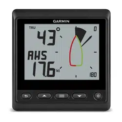
Keys
The keys on this instrument allow you to move through data screens, navigate menus, and turn the device on
and off. The functions of the keys depend on the device screen you are viewing.
Key Function
Press to turn the instrument on.
Press to change the backlight level.
Hold to turn the instrument off.
Press to move through the instrument screens and menu items.
Press to adjust the values of submenu settings.
Press to enter the menu when viewing an instrument screen.
Press to enter a submenu when viewing a menu item.
Press to select a value to adjust when viewing a submenu.
Press to confirm a setting after adjusting the value in a submenu.
Hold to enter the steer pilot mode (Steer-Pilot Mode, page 5).
Press to return to the instrument screens when viewing the menu.
Press to return to the menu when viewing a submenu.
Press to cancel a setting when adjusting the value in a submenu.
Getting Started 1
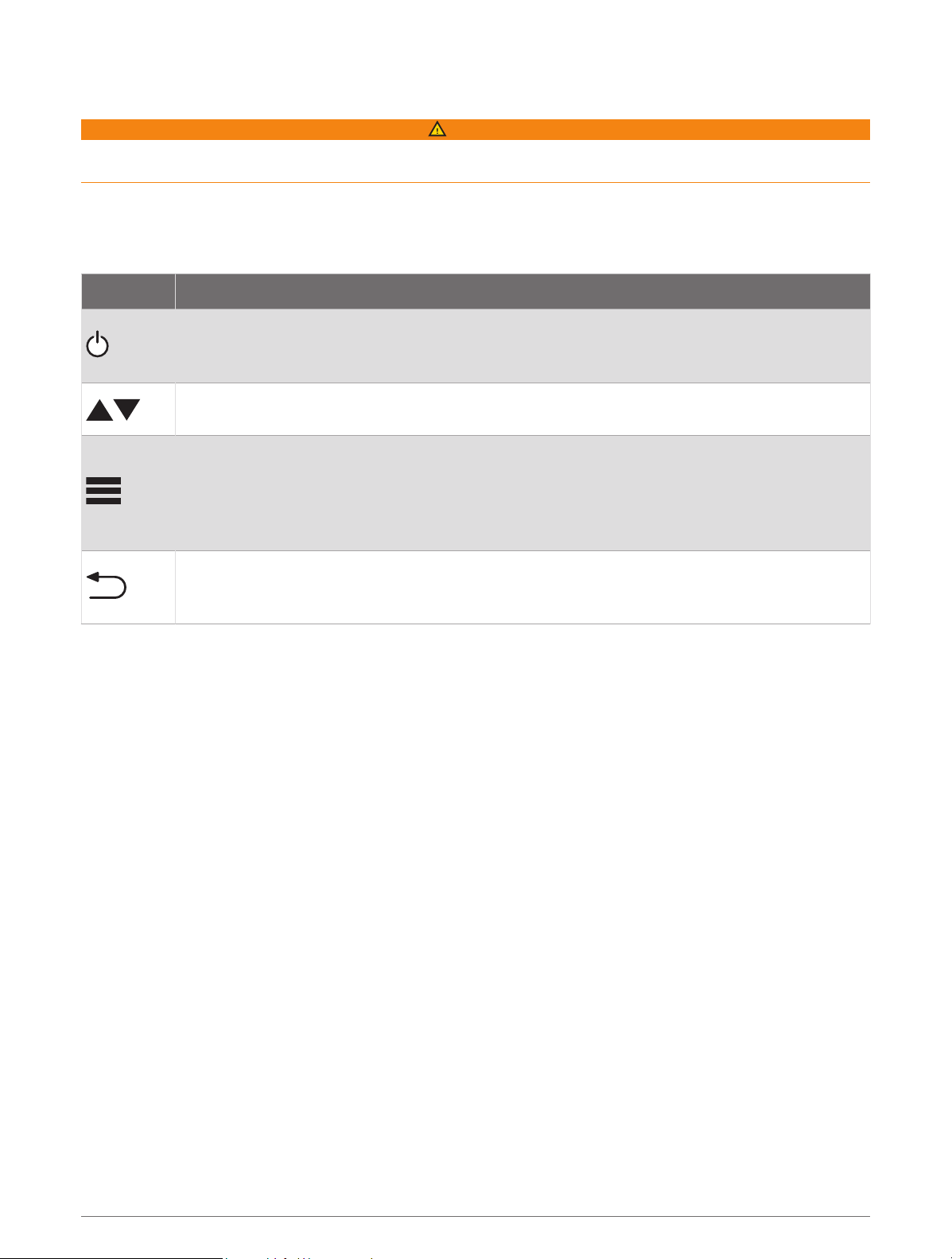
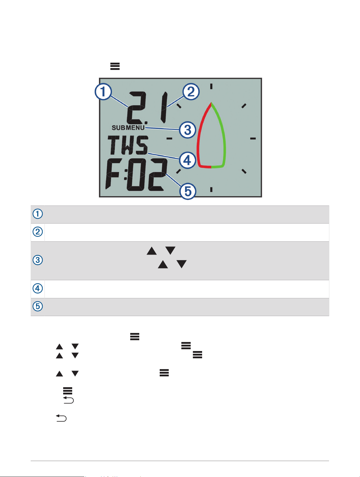
Instrument Screen
Item Description Notes
Upper data field
Instrument screen: shows numeric wind angle or direction information (Customizing an
Instrument Screen, page 9).
Menu screen: shows the decimal value of the menu category and sub-menu item.
Wind rose Shows wind direction or angle information on the boat diagram. (Wind Rose, page 2)
Wind rose span
Shows the scope of the wind rose, which changes when configured for close-hauled
sailing (Close-Hauled Wind Rose, page 4).
Lower data field
Instrument screen: shows sensor speed information (Customizing an Instrument
Screen, page 9).
Menu screen: shows the name of the menu category or name and value of the sub-
menu item.
Viewing Sensor Information
The instrument shows sensor information using up to four instrument screens. You can customize the number
of instrument screens (Adjusting the Number of Instrument Screens, page 9), and you can customize the data
shown on each instrument screen (Customizing an Instrument Screen, page 9).
1 When MENU or SUBMENU is shown, press repeatedly until you view an instrument screen.
2 Press and to move through the available instrument screens.
Wind Rose
The wind rose shows a visual representation of the wind angle or direction provided by the connected wind
sensor.
You can configure the wind rose to show three types of wind information on an instrument screen:
• Both the true wind angle and apparent wind angle at the same time
• A focused view for close-hauled sailing
• The true wind direction
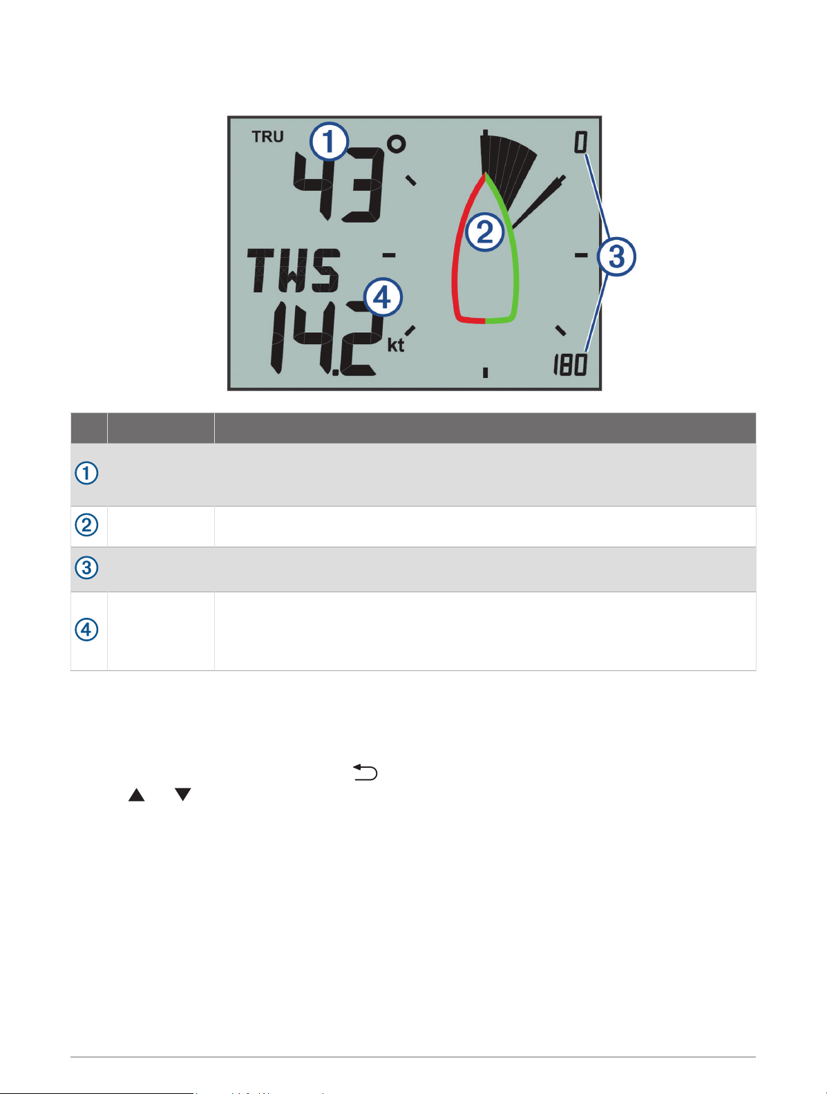
True and Apparent Wind Rose
When the center of the wind rose is empty, the wind rose shows both true and apparent wind angles using two
types of needles.
2 Getting Started
Shaded needle: the apparent wind angle (AWA)
Single needle: the true wind angle (TWA)
Getting Started 3
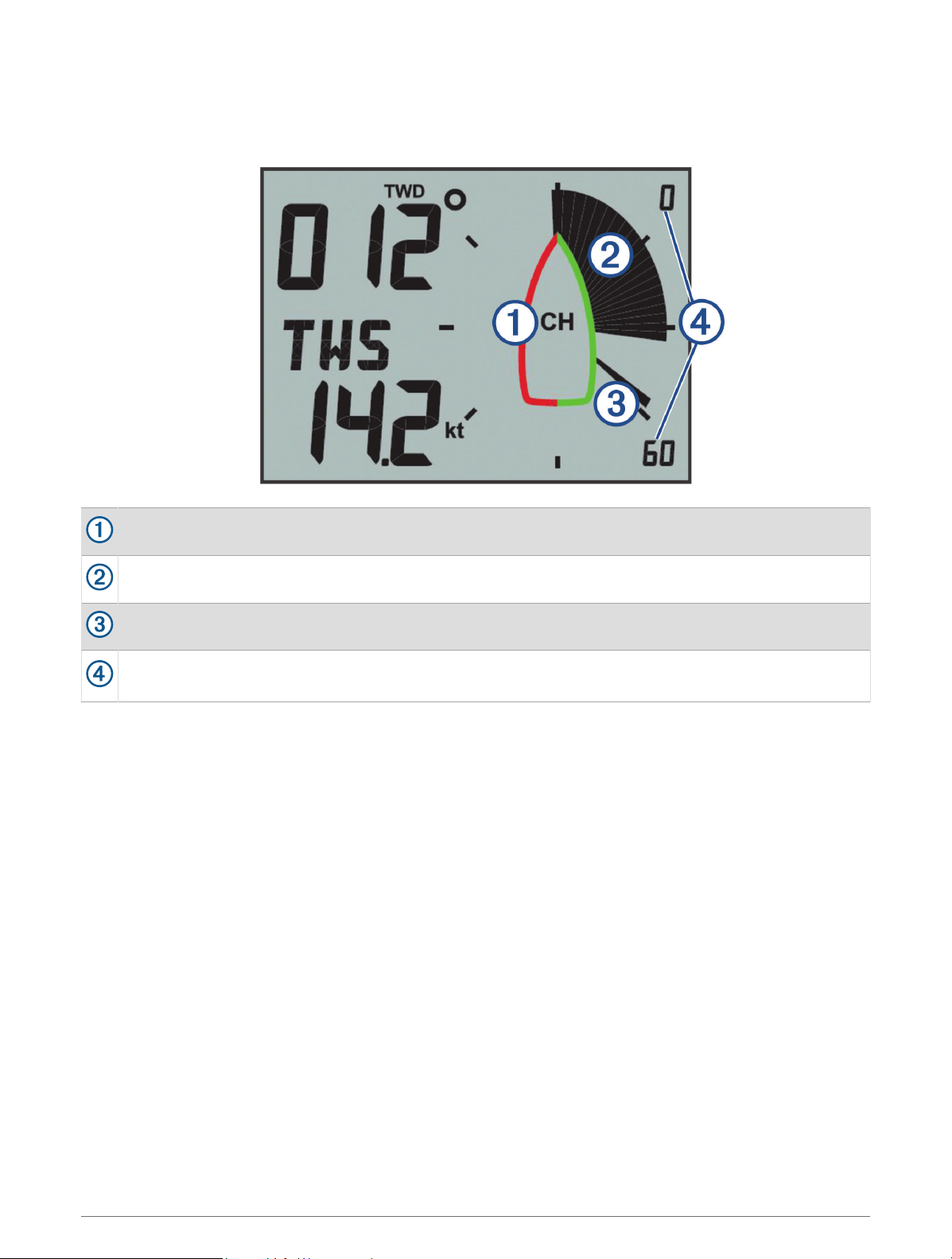
Close-Hauled Wind Rose
When CH appears in the center of the wind rose, the wind rose shows both the true and apparent wind angles in
a focused section for close-hauled sailing.
CH: the wind rose is focused for close-hauled (CH) sailing.
Shaded needle: the apparent wind angle (AWA)
Single needle: the true wind angle (TWA)
Wind rose scale: the scope of the focused area, which adjusts automatically based on the direction of the
boat.
4 Getting Started
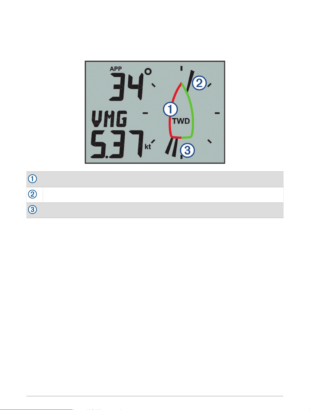
Wind Direction Wind Rose
When TWD appears in the center of the wind rose, the wind rose shows the true wind direction using two types
of needles. The needles indicate the true wind direction based on relative north. You should disregard the boat
symbol on the wind rose in this mode.
True wind direction (TWD): the wind rose is showing the true wind direction.
Single needle: the direction the wind is coming from.
Double needle: the direction the wind is heading to.
Steer-Pilot Mode
You can use the marine instrument to help you steer using a specific wind angle or information received from
connected sensors and a GPS device.
You can also use the marine instrument to help when tacking.
Steer-Pilot Mode 5
Using Steer-Pilot Mode with the AWA or TWA Setting
Before you can use steer-pilot mode with the Apparent Wind Angle (AWA) setting, you must connect the
instrument to a wind sensor, either wirelessly or through the NMEA 2000
®
network.
Before you can use steer-pilot mode with the True Wind Angle (TWA) setting, you must connect the instrument
to a wind sensor, either wirelessly or through the NMEA 2000 network, and you must connect it to a speed
sensor or GPS device through the NMEA 2000 network.
You can enter a specific wind-angle value and use the instrument as a steering guide when sailing.
1 From an instrument screen, hold .
The instrument enters steer-pilot mode.
2 Select an option:
• If AWA or TWA is shown, proceed to step 4.
• If something other than AWA or TWA is shown, hold until the text flashes.
3 Press or to select AWA or TWA, and press .
4 Press or to enter a numeric value for the wind angle to use when steering.
5 Press to confirm the wind angle.
6 Steer the boat while keeping the needle pointing straight ahead.
Using Steer-Pilot Mode with the TAWA or TTWA Setting
Before you can use steer-pilot mode with the Target Apparent Wind Angle (TAWA) or Target True Wind Angle
(TTWA) values, you must connect the instrument to a compatible chartplotter with a polar table loaded and
enabled.
You can enter use TAWA or TTWA to find the optimal wind-angle for maximum boat speed in the current
conditions and use the instrument as a steering guide when sailing.
1 From an instrument screen, hold .
The instrument enters steer-pilot mode.
2 Select an option:
• If TAWA or TTWA is shown, proceed to step 4.
• If something other than TAWA or TTWA is shown, hold until the text flashes.
3 Press or to select TAWA or TTWA, and press .
4 Steer the boat while keeping the needle pointing straight ahead.
Using Steer-Pilot Mode with the BTW or CTS Setting
Before you can use steer-pilot mode with the Bearing to Waypoint (BTW) setting, you must connect the
instrument to a GPS device through the NMEA 2000 network.
Before you can use steer-pilot mode with the Course to Steer (CTS) setting, you must connect the instrument to
a GPS device, a heading sensor, and a speed sensor through the NMEA 2000 network.
You can use the instrument to help you steer to a waypoint on a connected GPS device.
1 Begin navigating to a destination on the connected GPS device.
2 From an instrument screen, hold .
The instrument enters steer-pilot mode.
3 Select an option:
• If BTW or CTS is shown, proceed to step 5.
• If something other than BTW or CTS is shown, hold until the text flashes.
4 Press or to select BTW or CTS, and press .
5 Steer the boat while keeping the needle pointing straight ahead.
6 Steer-Pilot Mode
Using Steer-Pilot Mode with the MEM Settings
Before you can use steer-pilot mode with the Memory (MEM) settings, you must connect the instrument to a
heading sensor through the NMEA 2000 network.
The marine instrument can help you when tacking by using stored port and starboard tack angles.
1 From an instrument screen, hold .
The instrument enters steer-pilot mode.
2 Select an option:
• If MEM is shown, proceed to step 4.
• If something other than MEM is shown, hold until the text flashes.
3 Press or to select MEM, and press .
4 Begin tacking port or starboard.
5 After you make your first trim, push to store the heading value as MEM1.
6 Continue tacking.
7 After you make your second trim, push to store the heading value as MEM2.
8 Continue tacking while observing the needle.
When the needle moves from the center, it indicates the timing for the next tacking maneuver.
The MEM1 and MEM2 values change automatically as you are tacking.
Steer-Pilot Mode 7
Configuration
You can configure the instrument displays and settings using the configuration menu.
There are two levels in the configuration menu, indicated by the decimal value that appears in the upper-left side
of the screen when you press .
The value to the left of the decimal point indicates the primary menu category.
The value to the right of the decimal point indicates the sub-menu item within the primary menu category.
When MENU is shown, you can press or to move through the primary menu categories.
When SUBMENU is shown, you can press or to move through the sub-menu items within the
primary menu category.
The name of the primary menu category or sub-menu item.
The value of the menu or sub-menu item.
Changing a Configuration Setting
1 From an instrument screen, press .
2 Press or to select a MENU category, and press .
3 Press or to select a SUBMENU category, and press .
The value in the selected category flashes.
4 Press or to adjust the value, and press to confirm the setting.
5 Select an option:
• Press to confirm the new value and return to the SUBMENU category.
• Press to cancel all changes and return to the SUBMENU category.
The value in the selected category stops flashing.
6 Press two times to return to the instrument screens.
8 Configuration
Adjusting the Number of Instrument Screens
You can customize a maximum of four instrument screens.
1 From an instrument screen, press .
2 Press or to select SYST, and press .
3 Press or to select PGES, and press .
4 Press or to select the number of instrument screens (1 through 4), and press to confirm the
setting.
5 Press two times to return to the instrument screens.
Customizing an Instrument Screen
You can customize the data shown in the three main areas of each instrument screen.
1 From an instrument screen, press or to select an instrument screen to customize.
2 Press .
3 Press to select DATA.
4 Press or to select an option:
• Select SUBMENU 1.1 to change the lower-left (speed) value.
• Select SUBMENU 1.2 to change the upper-left (direction) value.
• Select SUBMENU 1.3 to change the wind rose function.
5 Press .
6 Press or to change the value.
7 Press to confirm the change.
8 Repeat steps 4 through 7 for every value or function you need to change on the current instrument screen.
9 Press two times to return to the instrument screens.
Connecting to a Garmin
®
Wearable Device
Your compatible Garmin wearable device communicates with the instrument using the Boat Data Garmin
Connect IQ
™
app. If this app is not already installed on your wearable device, you must download the app from
the Garmin Connect IQ store. See the owner's manual for your Garmin wearable device for more information
about Connect IQ apps.
You can connect to a compatible Garmin wearable device, such as a quatix
®
5, to view wind information from
the instrument.
1 From an instrument screen, press .
2 Press or to select WEAR, and press .
3 Select an option:
• If the setting for ENBL is set to OFF, press , press or to select ON, and press .
• If the setting for ENBL is set to ON, proceed to the next step.
4 Press or to select CONN, and press .
ADD appears on the screen.
5 Launch the Boat Data app on your Garmin wearable device to complete the connection to the instrument.
Configuration Menus
This section provides details for the items in the configuration menu, organized by menu and sub-menu decimal
values.
Configuration 9

1.0 DATA Configuration Settings
1.1 Lower data field configuration: Changes the speed type on the current instrument page.
1.2 Upper data field configuration: Changes the wind direction or angle type on the current instrument page.
1.3 Wind rose configuration: Changes the function of the wind rose on the current instrument page.
2.0 FILT Configuration Settings
In the filter configuration menu, you can adjust damping of the data received from the sensor before it is shown
in each data category (2.1 through 2.d).
The higher you set the filter value (0 through d) for each data category, more the data is dampened to remove
the more extreme readings. For example, setting a higher filter for TWS may provide a more stable wind-speed
reading in gusty conditions.
The glossary defines the data-type abbreviations used in this menu (Abbreviation Glossary, page 12).
3.0 UNIT Configuration Settings
3.1 WIND: Changes the units of measure used for wind speed.
3.2 BSP: Changes the units of measure used for boat speed.
3.3 NRTH: Changes the north reference for the heading and wind direction. MAG stands for magnetic north, TRU
stands for true north, and GRD stands for grid.
4.0 SENS Configuration Settings
4.1 WIND: Turns data from the connected wireless wind sensor on or off. When off, data from the connected
wireless wind sensor is not transmitted over the NMEA 2000 network.
4.2 ANGL: Adjusts the angle of the wind sensor to align with the front of the boat.
4.3 RSSI: Shows the signal strength between the instrument and the wireless wind sensor.
4.4 BSP%: Adjusts the calibration of boat speed information shown on the instrument.
NOTE: This adjustment affects the information as shown on the marine instrument only. Other devices using
speed information from the NMEA 2000 network must be calibrated separately, if needed.
5.0 WEAR Configuration Settings
5.1 ENBL: Enables the connection to a compatible Garmin wearable device.
5.2 CONN: Initiates a connection to a compatible Garmin wearable device.
10 Configuration
6.0 SYST Configuration Settings
6.1 LGHT: Adjusts the backlight level on a scale of 0 through 100%.
6.2 COLR: Sets the color of the instrument display.
Settings C00 through C06 are the custom colors available locally on the marine instrument.
Setting C07 is a custom-color setting controlled by other instruments on the NMEA 2000 network.
6.3 BEEP: Tuns the key-press sounds on or off.
6.4 POWR: Allows you to change how the instrument turns on.
The AuT option turns the instrument on automatically when the NMEA 2000 network turns on.
The OFF option keeps the instrument off when the NMEA 2000 network turns on. The instrument must be
turned on by pressing .
6.5 PGES: Sets the number of instrument pages.
6.6 SCRL: Sets and adjusts your instrument screens to scroll automatically. The value you set (1 through 9)
represents the number of seconds between each screen change.
A setting of OFF turns off scrolling.
6.7 FILT: Sets and adjusts the filter settings.
The SYN option syncs filter settings between the GNX Wind device and connected chartplotters and other
compatible instruments.
The LOC option restricts filter settings to the GNX Wind device. Settings are not shared with connected
chartplotters or other compatible instruments.
6.8 DFLT: Restores the marine instrument to factory default settings.
6.9 VER: Shows the installed software version.
Appendix
Specifications
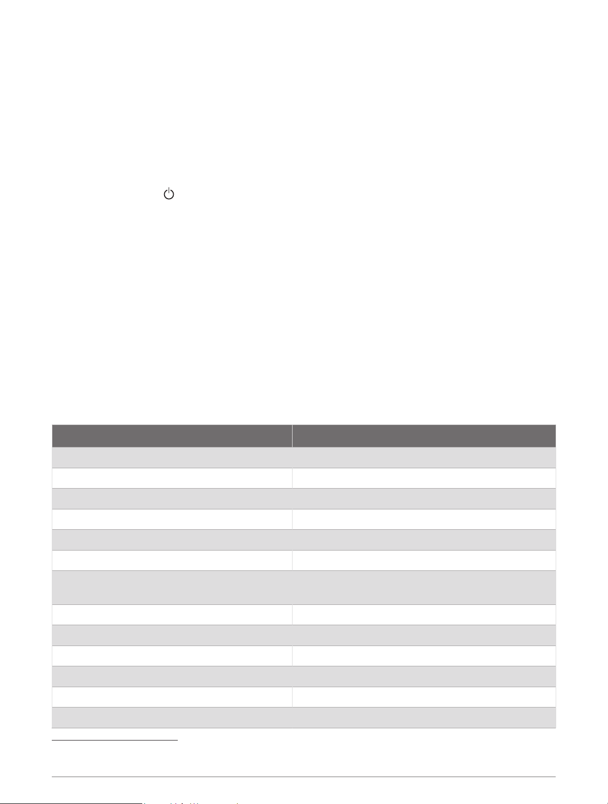
Specification Measurement
Dimensions without sun cover (H×W×D) 110 x 115 x 30 mm (4.33 x 4.53 x 1.18 in.)
Dimensions with sun cover (H×W×D) 115 x 120 x 35.5 mm (4.53 x 4.72 x 1.40 in.)
Weight without sun cover 247 g (8.71 oz.)
Weight with sun cover 283 g (9.98 oz.)
Temperature range From 5° to 158°F (from -15° to 70°C)
Compass-safe distance 209 mm (8.25 in.)
Material
Case: fully-gasketed polycarbonate
Lens: glass with an anti-glare finish
Water rating IEC 60529 IPX7
1
Power usage 1.35 W max
Unit max. voltage 32 Vdc
NMEA 2000 input voltage 9 to 16 Vdc
NMEA 2000 LEN @ 9 Vdc 3
NMEA 2000 draw 150 mA
1
The device withstands incidental exposure to water of up to 1 m for up to 30 min. For more information, go to www.garmin.com/waterrating.
Appendix 11

Abbreviation Glossary
This device uses abbreviations on many screens to indicate the menu, setting, or type of data being shown.
ALOG: (Analog sub menu) The filter sub menu that adjusts the dampening rate for wind data on the wind rose.
ANGL: (Angle sub menu) The sensor sub menu that adjusts the wind-angle offset of the data from the wind
sensor.
APP: (Apparent Wind Angle) Shown in the upper-left data field. The wind angle measured relative to the bow of
the vessel.
AWA: (Apparent Wind Angle) The wind angle measured relative to the bow of the vessel.
AWS: (Apparent Wind Speed) The measured speed of the wind.
BEEP: (Beep sub menu) The system sub menu that enables and disables key-press sounds.
BSP: (Boat Speed) The speed of the boat through the water.
BSP%: (Boat speed sub menu) The sensor sub menu that adjusts the speed data shown from a connected
speed sensor.
BTW: (Bearing to Waypoint) The direction of travel towards a destination waypoint.
COLR: (Color sub menu) The system sub menu that changes the color of the instrument display.
CTS: (Course to Steer) The calculated course to a destination, compensating for drift.
DATA: (Data menu) The menu category containing instrument page configuration items.
FILT: (Filter menu) The menu category containing data filter configuration items.
LGHT: (Backlight) The system sub menu that adjusts the backlight brightness level.
LOC: (Local) Filter settings only apply to the GNX Wind device.
MEM: (Memory: MEM1 and MEM2) Saved values for port and starboard, used when tacking in steer pilot mode.
PBS%: (Polar Boat Speed Percentage) The present boat speed as a percentage of the maximum possible boat
speed given the present wind speed and angle.
2
PGES: (Pages sub menu) The system sub menu that configures the number of instrument screens shown.
POWR: (Power sub menu) The system sub menu that enables auto power-on.
RSSI: (Signal strength sub menu) The sensor sub menu that shows the signal strength between the instrument
and the wireless wind sensor.
SENS: (Sensor menu) The menu category containing sensor configuration items.
STR: (Steer sub menu) The filter sub menu that adjusts the update rate for the steering guide.
SYN: (Sync) Filter settings are synchronized with connected devices.
SYST: (System menu) The menu category containing system configuration items.
TAWA: (Target Apparent Wind Angle) The apparent wind angle that provides the highest velocity made good
against the wind given the present wind direction and speed.
2
TBS%: (Target Boat Speed Percentage) The present boat speed as a percentage of the maximum possible boat
speed at the target wind angle.
2
TRU: (True Wind Angle) Shown in the upper-left data field. The angle of the wind, compensated by the forward
speed of the vessel.
TTWA: (Target True Wind Angle) The true wind angle that provides the highest velocity made good against the
wind given the present wind direction and speed.
2
TWA: (True Wind Angle) The angle of the wind, compensated by the forward speed of the vessel.
TWD: (True Wind Direction) The true direction of the wind relative to north.
TWS: (True Wind Speed) The speed of the wind, compensated by the forward speed of the vessel.
VMG: (Velocity Made Good).
WIND: (Wind sub menu) The unit sub menu that adjusts the units of measure used to represent wind speed.
WIND: (Wind transducer sub menu) The sensor sub menu that turns on and off data from the connected wind
sensor.
2
Before you can view this value, you must connect the instrument to a compatible chartplotter with a polar table loaded and enabled.
12 Appendix
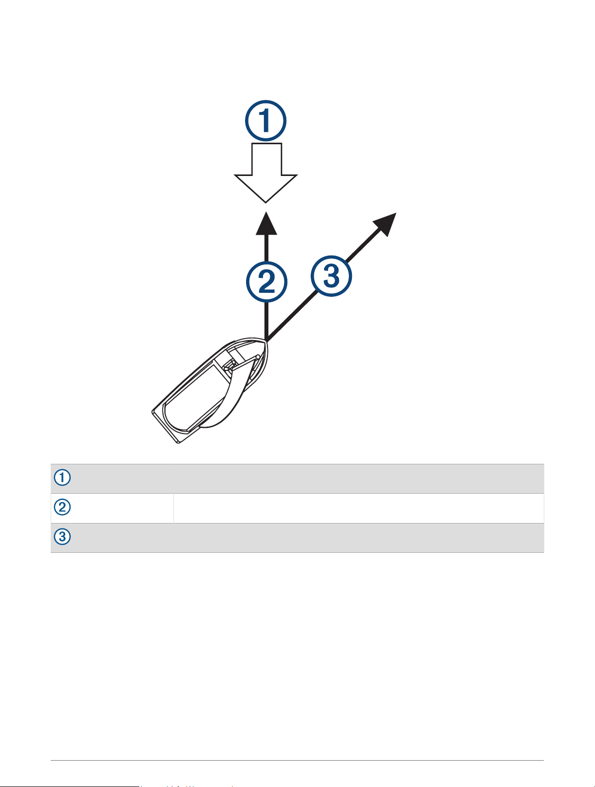
Velocity Made Good
Velocity made good (VMG) is the speed into or away from the wind. VMG is calculated using boat-speed data
from sensors on the NMEA 2000 network.
Wind direction
VMG
Boat speed
Appendix 13

support.garmin.com
GUID-6A13DE9A-5914-44D6-ACBB-3A1F90360E86 v5June 2022