Loading ...
Loading ...
Loading ...

English
6
SHOCKS® Active Vibration Control
System
For best vibration control, hold the tool as described in
Proper Hand Position and apply just enough pressure so
the damping device on the main handle is approximately
mid stroke. The hammer only needs enough pressure to
engage the active vibration control. Applying too much
pressure will not make the tool actuate faster and active
vibration control will notengage.
DeWALT
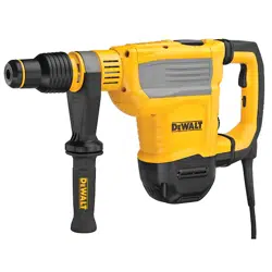
Tool Tag Ready (Fig. A)
Optional Accessory
Your hammer comes with mounting holes
11
and
fasteners for installing a
DeWALT
Tool Tag. You will need a
T15 bit tip to install the tag. Only use the screws provided.
The
DeWALT
Tool Tag is designed for tracking and locating
professional power tools, equipment, and machines using
the
DeWALT
Tool Connect™ app. For proper installation
and use of the
DeWALT
Tool Tag refer to the
DeWALT
Tool
Tagmanual.
Lock-On Button (Fig. A)
Hammering mode only
The lock-on button
8
offers increased comfort in extended
use applications. To lock the tool on, depress the lock-on
button while the tool is running. The tool will continue to
run after the switch is released. To unlock and turn off the
tool, depress and release theswitch.
nOTE: The lock-on button will not function in Rotary
hammeringmode.
Electronic Speed and Impact Control (Fig.A)
The electronic speed and impact control allows the
use of smaller drill bits without the risk of bit breakage,
hammerdrilling into light and brittle materials without
shattering and optimal tool control for precisechiseling.
To set the speed dial
9
, turn the dial to the desired level.
The higher the number, the greater the speed and impact
energy. Dial settings make the tool extremely flexible and
adaptable for many different appli cations. The required
setting depends on the bit size and hardness of material
beingdrilled.
Overload Clutch
In case of jamming of a drill bit, the drive to the drill spindle
is interrupted by the overload clutch. Due to the resulting
forces, always hold the tool with both hands and take a
firmstance. After the overload, release and depress the
trigger to re-engagedrive.
WARNING: Drill may stall if overloaded causing a
sudden twist. Always expect the stall. Grip the drill
firmly to control the twisting action and avoidinjury.
E-Clutch® System (Fig. A)
In addition to the integral (mechanical) clutch, the
DeWALT
anti-rotation E-Clutch® system, offers technology capable
of detecting the motion of the tool. This feature senses the
motion of the tool and shuts it down if necessary. The red
indicator LED
10
illuminates when the E-Clutch® System
isengaged.
E-Clutch® and Service Indicator LEDs
(Fig.A)
Your rotary hammer has two LEDs
10
, indicating the
E-Clutch® (ADC) function and a service indicator. Refer to
the table for more information on LEDfunctionality.
lED Function Description
Red
(flashing)
lock-on/service
The red indicator LED
10
lights
up if the lock-on button
8
is used
in any mode except the chipping
mode or if there is a fault with
the tool or the brushes have
completely worn out
Red
(permanently on)
E-Clutch®
E- Clutch® is engaged.
Yellow
(permanently on)
Brush service
The yellow brushwear indicator
LED
10
lights up when the
carbon brushes are nearly worn
out, indicating that the tool needs
servicing within the next 8 hours
ofuse.
Operation Modes (Fig.E)
WARNING: Do not select the operating mode when
the tool isrunning.
CAUTION: Never use in Rotary Drilling or Rotary
Hammering mode with a chisel bit in the bit holder.
Personal injury and damage to the the tool mayresult.
Your tool is equipped with a mode selector dial
4
to
selectthe mode appropriate to desiredoperation.
symbol Mode Application
Rotary
hammering
Drilling into concrete
and masonry
hammering
only
Chipping
Bit Adjustment
Chisel bit position
adjustment
To select an operating mode
• Rotate the mode selector dial
4
so that the
arrow points to the symbol corresponding for the
desiredmode.
Loading ...
Loading ...
Loading ...