
Version: V1.00.000
Revised date: 2020-03-26

LAUNCH Coypright & Safety Precautions
i
Copyright Information
Copyright © 2020 by LAUNCH TECH CO., LTD. All rights reserved. No part of
this publication may be reproduced, stored in a retrieval system, or transmitted
in any form or by any means, electronic, mechanical, photocopying, recording or
otherwise, without the prior written permission of LAUNCH. The information
contained herein is designed only for the use of this unit. LAUNCH is not
responsible for any use of this information as applied to other units.
Neither LAUNCH nor its affiliates shall be liable to the purchaser of this unit or
third parties for damages, losses, costs, or expenses incurred by purchaser or
third parties as a result of: accident, misuse, or abuse of this unit, or
unauthorized modifications, repairs, or alterations to this unit, or failure to strictly
comply with LAUNCH operating and maintenance instructions. LAUNCH shall
not be liable for any damages or problems arising from the use of any options or
any consumable products other than those designated as Original LAUNCH
Products or LAUNCH Approved Products by LAUNCH.
Trademark Information
LAUNCH is a registered trademark of LAUNCH TECH CO., LTD. (also called
LAUNCH for short) in China and other countries. All other LAUNCH trademarks,
service marks, domain names, logos, and company names referred to in this
manual are either trademarks, registered trademarks, service marks, domain
names, logos, company names of or are otherwise the property of LAUNCH or
its affiliates. In countries where any of the LAUNCH trademarks, service marks,
domain names, logos and company names are not registered, LAUNCH claims
other rights associated with unregistered trademarks, service marks, domain
names, logos, and company names. Other products or company names referred
to in this manual may be trademarks of their respective owners. You may not
use any trademark, service mark, domain name, logo, or company name of
LAUNCH or any third party without permission from the owner of the applicable
trademark, service mark, domain name, logo, or company name. You may
contact LAUNCH by visiting the website at www.cnlaunch.com, or writing to
LAUNCH TECH CO., LTD.,Launch Industrial Park, North of Wuhe Avenue,
Banxuegang, Bantian, Longgang, Shenzhen, Guangdong, P.R.China, to request
written permission to use Materials on this manual for purposes or for all other
questions relating to this manual.

LAUNCH Coypright & Safety Precautions
ii
Important Safety Precautions
Important: To avoid personal injury, property damage, or accidental damage to
the product, read all of the information in this section before using the product.
y
Never collide, throw, or puncture the tool, and avoid falling, extruding and
bending it.
y
Do not insert foreign objects into or place heavy objects on your device.
Sensitive components inside might cause damage.
y
Do not use the tool in exceptionally cold or hot, dusty, damp or dry
environments.
y
In places using the tool may cause interference or generate a potential risk,
please turn it off.
y
The tool is a sealed unit. There are no end-user serviceable parts inside. All
internal repairs must be done by an authorized repair facility or qualified
technician. If there is any inquiry, please contact the dealer.
y
Never place the tool into apparatus with strong electromagnetic field.
y
Keep the tool far away from magnetic devices because its radiations can
damage the screen and erase the data stored on the tool.
y
DANGER: Do not attempt to replace the internal rechargeable lithium battery.
Contact the dealer for factory replacement.
y
CAUTION: Please use the included battery and charger. Risk of explosion if
the battery is replaced with an incorrect type.
y
Do not delete unknown files or change the name of files or directories that
were not created by you, otherwise your software might fail to work.
Precautions on using the tool
Before using this test equipment, please read the following safety information
carefully.
y
Always perform automotive testing in a safe environment.
y
Wear an ANSI-approved eye shield when testing or repairing vehicles.
y
The vehicle shall be tested in a well ventilated work area, as engines produce
various poisonous compounds (hydrocarbon, carbon monoxide, nitrogen
oxides, etc.)
y
Do not connect or disconnect any test equipment while the ignition is on or

LAUNCH Coypright & Safety Precautions
iii
the engine is running.
y
Put blocks in front of the drive wheels and never leave the vehicle unattended
while testing.
y
Keep the test equipment dry, clean, free from oil, water or grease. Use a mild
detergent on a clean cloth to clear the outside of the equipment as
necessary.
y
Do not drive the vehicle and operate the test equipment at the same time.
Any distraction may cause an accident.
y
Keep clothing, hair, hands, tools, test equipment, etc. away from all moving or
hot engine parts.
y
Before starting the engine, put the gear lever in the Neutral position (for
manual transmission) or in the Park (for automatic transmission) position to
avoid injury.
y
To avoid damaging the test equipment or generating false data, please make
sure the vehicle battery is fully charged and the connection to the vehicle
DLC (Data Link Connector) is clear and secure.
y
Automotive batteries contain sulfuric acid that is harmful to skin. In operation,
direct contact with the automotive batteries should be avoided. Keep the
ignition sources away from the battery at all times.
Precautions on operating vehicle’s ECU
y
Do not disconnect battery or any wiring cables in the vehicle when the ignition
switch is on, as this could avoid damage to the sensors or the ECU.
y
Do not place any magnetic objects near the ECU. Disconnect the power
supply to the ECU before performing any welding operations on the vehicle.
y
Use extreme caution when performing any operations near the ECU or
sensors. Ground yourself when you disassemble PROM, otherwise ECU and
sensors can be damaged by static electricity.
y
When reconnecting the ECU harness connector, be sure it is attached firmly,
otherwise electronic elements, such as ICs inside the ECU, can be damaged.
FCC Warning
Any Changes or modifications not expressly approved by the party responsible
for compliance could void the user’s authority to operate the equipment.

LAUNCH Coypright & Safety Precautions
iv
This device complies with Part 15 of the FCC Rules. Operation is subject to the
following two conditions:
(1) This device may not cause harmful interference, and
(2) This device must accept any interference received, including interference
that may cause undesired operation.
Note: This equipment has been tested and found to comply with the limits for a
Class B digital device, pursuant to Part 15 of the FCC Rules. These limits are
designed to provide reasonable protection against harmful interference in a
residential installation. This equipment generates, uses, and can radiate radio
frequency energy, and if not installed and used in accordance with the
instructions, may cause harmful interference to radio communications. However,
there is no guarantee that interference will not occur in a particular installation. If
this equipment does cause harmful interference to radio or television reception,
which can be determined by turning the equipment off and on, the user is
encouraged to try to correct the interference by one or more of the following
measures:
– Reorient or relocate the receiving antenna.
– Increase the separation between the equipment and receiver.
– Connect the equipment into an outlet on a circuit different from that to which
the receiver is connected.
– Consult the dealer or an experienced radio/TV technician for help.
The device has been evaluated to meet general RF exposure requirement. The
antenna(s) used for this transmitter must not transmit simultaneously with any
other antenna or transmitter, except in accordance with FCC multi-transmitter
product procedures. The highest reported SAR value is 0.950W/kg. This device
has a 20MHz and 40MHz bandwidth mode.
Hereby, Launch Tech Co., Ltd. declares that this AUTO Smart Diagnostic Tool
(Model X-431 Diagun v) is in compliance with the essential Requirements and
other relevant provisions of Radio Equipment Directive 2014/53/EU.
Operation frequency and Max. RF output power:
WiFi 802.11b/g/n(2.4G): 2412-2472MHz, 17.77dBm;
Bluetooth 2402-2480MHz, 9.72dBm;
The RF frequencies can be used in Europe without restriction.

LAUNCH Table of Contents
v
TABLE OF CONTENTS
1 INTRODUCTIONS ........................................................................................... 1
1.1 P
RODUCT PROFILE ..................................................................................... 1
1.2 F
EATURES .................................................................................................. 1
1.3 C
OMPONENTS & CONTROLS ....................................................................... 1
1.3.1 Display Tablet ................................................................................... 2
1.3.2 VCI Connector (Only applies to 12V passenger cars) ..................... 5
1.4 T
ECHNICAL PARAMETERS ........................................................................... 6
1.5 P
ACKAGE LIST ............................................................................................ 6
2 PREPARATIONS ............................................................................................. 8
2.1
CHARGING THE TABLET .............................................................................. 8
2.2
USING YOUR BATTERY ................................................................................ 8
2.3
POWER ON/OFF .......................................................................................... 8
2.3.1 Power on ........................................................................................... 8
2.3.2 Power off ........................................................................................... 8
2.4
TIPS ON FINGER OPERATIONS ..................................................................... 9
2.5
SCREEN LAYOUT ........................................................................................ 9
2.6
ADJUST BRIGHTNESS ............................................................................... 10
2.7
CHANGE SYSTEM LANGUAGE ................................................................... 10
2.8
SET STANDBY TIME .................................................................................. 10
3 NETWORK SETUP ........................................................................................ 11
3.1
CONNECT TO A WLAN NETWORK ............................................................. 11
3.2
DISCONNECT FROM A WLAN NETWORK ................................................... 11
4 GETTING STARTED & VEHICLE CONNECTION ....................................... 12
4.1
DIAGNOSIS FLOWCHART .......................................................................... 12
4.2
GETTING STARTED ................................................................................... 12
4.2.1 User registration ............................................................................. 13
4.2.2 Job menu ........................................................................................ 15
4.3
CONNECTIONS ......................................................................................... 16
4.3.1 Preparation ..................................................................................... 16

LAUNCH Table of Contents
vi
4.3.2 DLC location ................................................................................... 16
4.3.3 Vehicle connection .......................................................................... 17
4.4
COMMUNICATION SETUP .......................................................................... 18
5 START DIAGNOSTICS ................................................................................. 19
5.1
HEALTH REPORT (QUICK TEST)................................................................ 19
5.1.1 View fault report .............................................................................. 21
5.1.2 Clear DTC ....................................................................................... 22
5.2
SYSTEM SCAN ......................................................................................... 23
5.3
SYSTEM SELECTION ................................................................................. 23
5.3.1 Version Information ......................................................................... 25
5.3.2 Read Fault Code ............................................................................ 25
5.3.3 Clear Fault Code ............................................................................ 26
5.3.4 Read Data Stream .......................................................................... 26
5.3.5 Actuation Test ................................................................................. 31
5.3.6 Special Function ............................................................................. 32
6 RESET ........................................................................................................... 33
6.1
OIL RESET SERVICE ................................................................................. 34
6.2
ELECTRONIC PARKING BRAKE RESET....................................................... 34
6.3
STEERING ANGLE CALIBRATION ............................................................... 35
6.4
ABS BLEEDING ........................................................................................ 35
6.5
TIRE PRESSURE MONITOR SYSTEM RESET .............................................. 35
6.6
GEAR LEARNING ...................................................................................... 35
6.7
IMMO SERVICE ....................................................................................... 36
6.8
INJECTOR CODING ................................................................................... 36
6.9
BATTERY MAINTENANCE SYSTEM RESET ................................................. 37
6.10
DIESEL PARTICULATE FILTER (DPF) REGENERATION ............................. 37
6.11
ELECTRONIC THROTTLE POSITION RESET .............................................. 38
7 FEEDBACK ................................................................................................... 39
8 SOFTWARE UPGRADE ............................................................................... 41
8.1
UPDATE DIAGNOSTIC SOFTWARE & APP.................................................. 41
8.2
RENEW SUBSCRIPTION ............................................................................ 42

LAUNCH Table of Contents
vii
9 PERSONAL CENTER ................................................................................... 45
9.1
MY REPORT ............................................................................................. 45
9.2
MY CONNECTOR ...................................................................................... 45
9.3
ACTIVATE CONNECTOR ............................................................................ 45
9.4
FIRMWARE FIX ......................................................................................... 46
9.5
MY ORDER .............................................................................................. 46
9.6
INQUIRE SUBSCRIPTION RENEWAL CARD STATUS .................................... 46
9.7
PROFILE .................................................................................................. 47
9.8
CHANGE PASSWORD ................................................................................ 47
9.9
SETTINGS ................................................................................................ 47
9.9.1 Units of Measurement .................................................................... 47
9.9.2 About ............................................................................................... 48
9.9.3 Log out ............................................................................................ 48
10 OTHERS ...................................................................................................... 49
10.1
SYNCHRONIZATION ................................................................................ 49
10.1.1 Connect to PC .............................................................................. 49
10.1.2 Run on PC .................................................................................... 49
10.1.3 Install an application ..................................................................... 49
10.2
CLEAR CACHE ....................................................................................... 49
11 FAQ .............................................................................................................. 50

LAUNCH Introductions
1
1 Introductions
1.1 Product Profile
Featuring a quad-core processor, and a 5.5 inch capacitive screen, X-431
Diagun v delivers diagnostic functionality which helps to diagnose vehicle issues
more efficiently.
In addition, the tablet supports WLAN connection, one-click update, diagnostic
feedback and all kinds of common service functions.
1.2 Features
1. Diagnostics:
A. Diagnose
Diagnose the electronic control systems of prevailing vehicle models
covering Asian, European, American and Chinese. Diagnosis functions
include: Read DTCs, Clear DTCs and Read data stream etc.
Specially designed for Android platform with clear and user-friendly
interface.
B. Special function: some common maintenance and reset items including
Oil lamp reset, DPF regeneration, ABS bleeding etc. can be done.
C. Feedback: enables you to submit the vehicle issue to us for analysis and
troubleshooting.
D. One-click Update: lets you update diagnostic software and APK more
efficiently.
2. Browser: built-in WLAN module makes surfing on the internet freely.
3. Email: allows you to send and receive emails.
4. Settings: configures personalized tablet through it.
5. Applications: other android based applications can be customized to install
or uninstall.
1.3 Components & Controls
There are two main components to the diagnostic system:
LAUNCH Introductions
2
y
Display tablet
-- the central system and monitor for the system (for details,
please refer to Chapter 1.3.1).
y
VCI connector
-- the Vehicle Communication Interface for accessing vehicle
data (for details, please refer to Chapter 1.3.2).
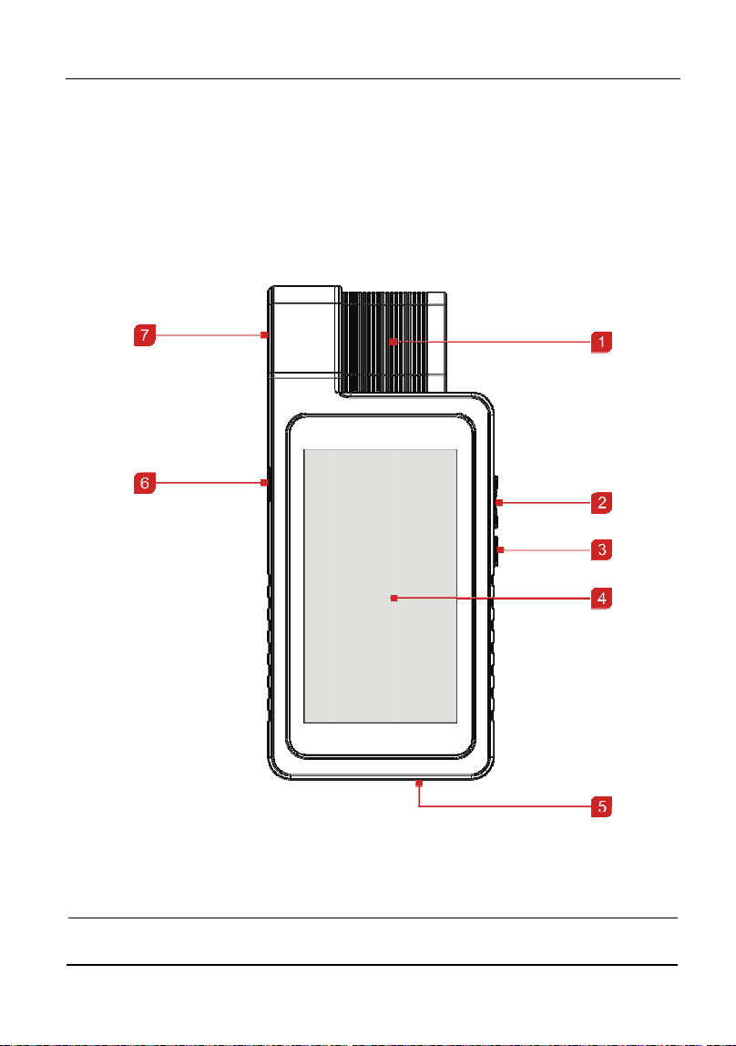
1.3.1 Display Tablet
Fig. 1-1 Front View
1
V
CI connecto
r
2
VOLUME +/- Key
To adjust the volume.

LAUNCH Introductions
3
To print the screen, hold and press the
POWER and VOLUME – key until a
snapshot pops up on the screen. The
captured snapshot is saved in the
“Screenshots” folder.
3
POWER/Screen lock
key
In Off mode, press it for 3 seconds to turn
the tablet on.
In On mode:
Press it to activate the LCD if the LCD is
off.
Press it to turn off the LCD if the LCD
lights up.
Press it for 3 seconds to turn it off.
Press it for 8 seconds to perform forced
shutdown.
4
LCD screen
5
Microphone
6
Charging port
Connects the power adaptor for charging
the tablet.
7
Slot for VCI connector
For housing the VCI connector.
Note: When the VCI connector is not in use,
please insert it into the slot to avoid loss.
LAUNCH Introductions
4
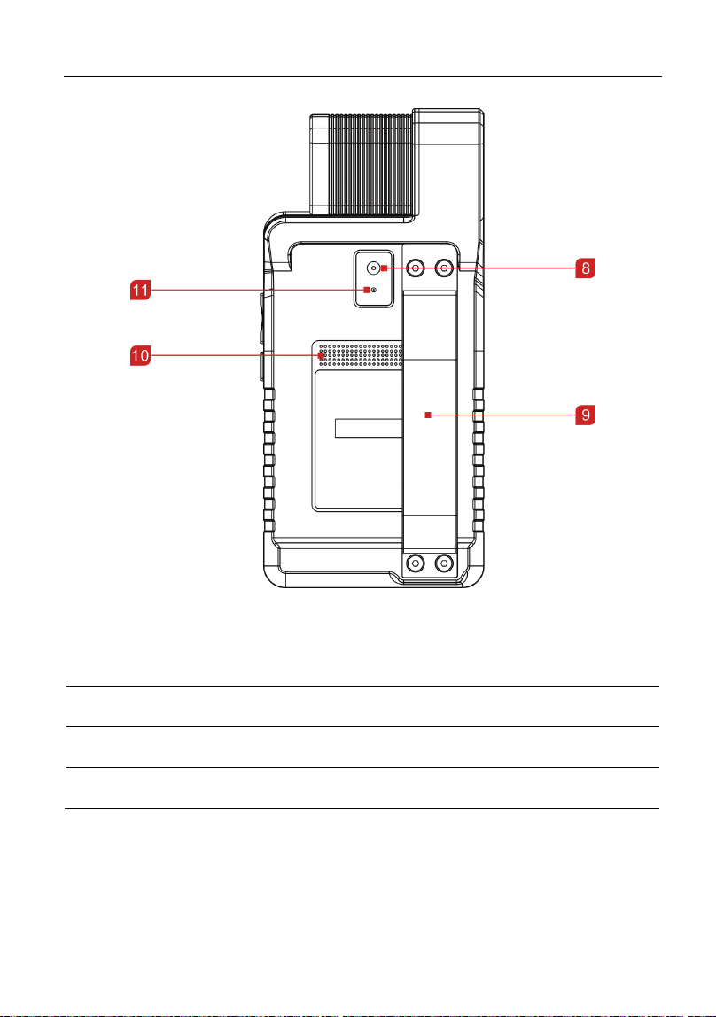
Fig. 1-2 Rear View
8
Rear camera
9
Soft rubber belt
10
Speakers
11
Camera flash
LAUNCH Introductions
5
1.3.2 VCI Connector (Only applies to 12V passenger cars)
The VCI connector works as a vehicle communication interface device, which is
used to connect to the vehicle’s DLC (Data Link Connector) socket directly or via
OBD II extension cable to read the vehicle data and then send it to the tablet via
wireless BT communication.
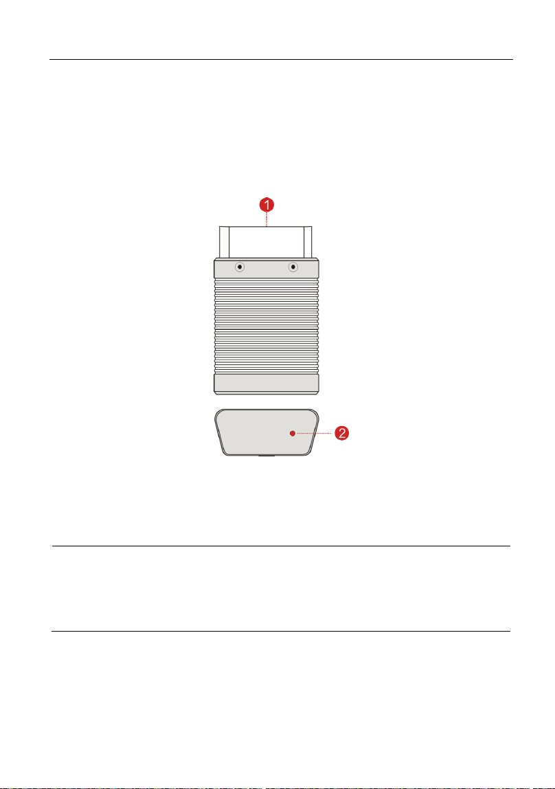
Fig. 1-3 VCI connector
1
OBD-16 diagnostic
connector
Connect to the vehicle’s DLC or OBD II
extension cable.
2
Mode indicator
y It illuminates red when the VCI connector is
connected to the vehicle’s DLC.
y Blue indicates the VCI connector is working
in wireless BT communication mode.

LAUNCH Introductions
6
1.4 Technical Parameters
Display tablet:
Operating system
Android
Processo
r
Quad core
Memory
2GB
Storage
32GB
LCD screen
5.5 inch high definition screen with a resolution of
1280 x 720 pixels
Camera
Rear-facing 5MP camera
Working temperature 0℃ ~ 50℃
VCI connector:
Working voltage
9~18V
Working temperature
0℃ ~ 50℃
Storage temperature
-20 ~ 70℃℃
Relative humidity
20% ~ 90%
1.5 Package List
While opening the package for the first time, please carefully check the following
components. Common accessories are same, but for different destinations, the
accessories may vary. Please consult from the local agency or check the
package list supplied with the tool together.
y Display tablet
y VCI connector (For connecting OBD II vehicles)
y Password envelope (A piece of paper bearing Product S/N and Activation
Code for product registration)
y OBD II extension cable (For connecting the VCI connector to OBD II vehicle)

LAUNCH Introductions
7
y OBD I adaptor (Optional. For connecting the non-16pin connector and the
VCI connector)
y Cigarette lighter cable (Optional. To supply power to the non-16pin connector
from the vehicle’s cigarette lighter receptacle)
y Battery clamps cable (Optional. To supply power to the non-16pin connector
from the vehicle’s battery)
y Power adaptor (For charging the tablet)
y Non-16pin connectors (Optional. For connecting vehicles equipped with
non-OBD II management system)

LAUNCH Initial Setup
8
2 Preparations
2.1 Charging the tablet
1. Plug one end of the included power adaptor into the charging port of the
tablet.
2. Connect the other end to the AC outlet.
If
appears on the screen, it indicates it is being charged. If the logo changes
into
, it indicates that the battery is fully charged. Unplug the power adaptor
from the tablet.
2.2 Using your battery
If the battery remains unused for a long period of time or the battery is
completely discharged, it is normal that the tool will not power on while being
charged. Please charge it for a period of 5 minutes and then turn it on.
Please use the included power adaptor to charge your tool. No responsibility
can be assumed for any damage or loss caused as a result of using power
adaptors other than the one supplied.
While the tablet has low battery, a beep will sound. If it is very low, the tablet
will be switched off automatically.
2.3 Power on/off
2.3.1 Power on
Press [POWER] to turn the tool on.
*Note: If it is the first time you have used this tool or the tool remains idle for a long
period of time, the tool could fail to turn on. Please charge the tool for a minimum of 5
minutes and attempt to turn on again.
2.3.2 Power off
Press [POWER] for 3 seconds, an option menu will pop up on the screen. Tap
“Power off” to turn the tool off.
LAUNCH Initial Setup
9
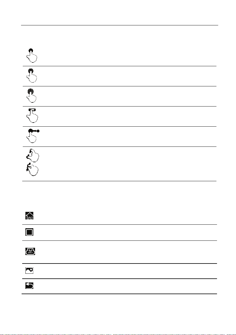
2.4 Tips on finger operations
Single-tap: To select an item or launch a program.
Double-tap: To zoom in so that the text on a webpage appears in a
column that fits your device’s screen.
Long press: Tap and hold on the current interface or area until a
contextual menu pops up on the screen, and then release it.
Slide: To jump to different pages.
Drag: Tap the application icon and drop it to other location.
Spread apart
/
pinch togethe
r
: To zoom in manually, place two
fingers on the screen and then spread them apart. To zoom out,
place two fingers apart on the screen and then pinch them
together.
2.5 Screen layout
There are five on-screen buttons available on the bottom of the screen.
HOME
Tap it to navigate to the Android’s home screen.
RECENT APP
Tap it to view the currently running applications.
VCI STATUS
Shows whether the VCI device is properly
connected or not.
SCREENSHOT
Tap it to capture the current screen.
BACK
Tap it to return to the previous screen.

LAUNCH Initial Setup
10
2.6 Adjust brightness
Tips: Reducing the brightness of the screen is helpful to conserve the battery power.
1. On the home screen, tap Settings -> Display -> Brightness level.
2. Drag the slider to adjust it.
2.7 Change System Language
The tool supports multiple system languages. To change the language of the
tool, please do the following:
1. On the home screen, tap Settings -> Language & Input -> Languages.
2. Tap Add a language, and then choose the desired language from the list.
3. Tap and hold the desired language and drag it to the top of the screen and
then release it, the system will change into the target language.
2.8 Set Standby time
If no activities are made within the defined standby period, the screen will be
locked automatically and the system enters sleep mode to save power.
1. On the home screen, tap Settings -> Display -> Sleep.
2. Choose the desired sleep time.

LAUNCH Network Setup
11
3 Network Setup
*Note: If you don’t need to use WLAN for a while, you can turn it off to conserve
battery life.
The tablet has built-in WLAN module that can be used to get online. Once you’re
online, you can register App, surf the Internet, get apps, send email, and check
for software updates etc.
3.1 Connect to a WLAN network
1. On the home screen, tap
Settings -> WLAN
.
2. Slide the switch to ON, the tablet will start searching for all available wireless
networks.
3. Select a desired wireless network,
y
If the chosen network is open, the tablet will connect automatically;
y
If the selected network is encrypted, a network password will need to be
entered.
4. When “Connected” appears, it indicates the WLAN connection is complete.
*Note: When WLAN is not required, this should be disabled to conserve battery power.
When this tool is in range, it will connect to the previously linked network
automatically.
3.2 Disconnect from a WLAN network
1. On the home screen, tap
Settings -> WLAN
.
2. Tap the network with a
Connected
status, then tap “Disconnect”.
LAUNCH Getting Started & Connections
12
4 Getting Started & Vehicle Connection
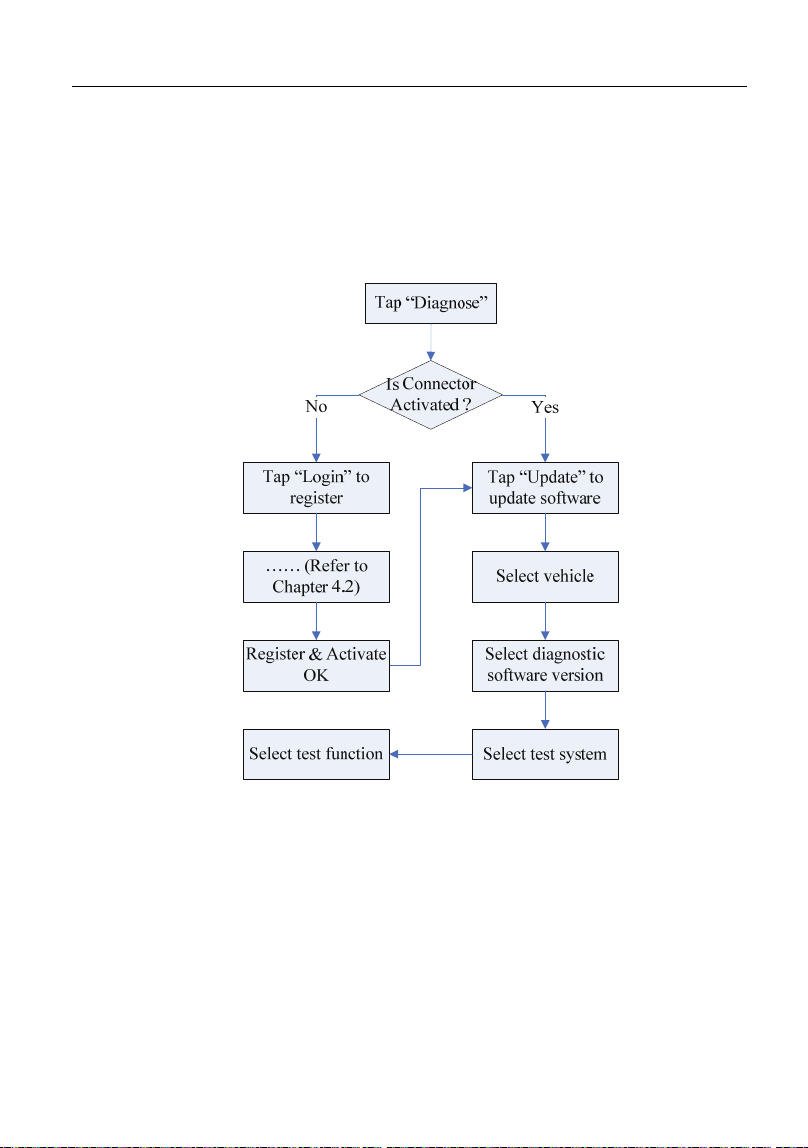
4.1 Diagnosis Flowchart
For new users, please follow the operation chart shown in Fig. 4-1 to get familiar
with and start using this tool.
Fig. 4-1
4.2 Getting Started
During initial use, tap the application icon on the home screen to launch it and
enter the main menu screen.
By default, all software is pre-installed on the tablet and can be used to diagnose
vehicles even if you do not experience the product registration. To enable you to
get one-click update and enjoy more functions and better service, you are
recommended to make app sign-up and product activation for the first time.
LAUNCH Getting Started & Connections
13
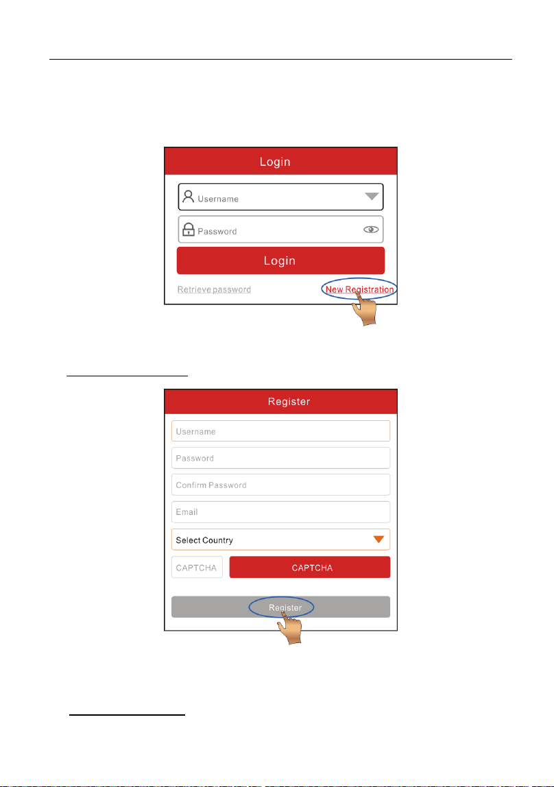
4.2.1 User registration
Tap “Login” on the upper right corner of the Job menu, the following window will
pop up on the screen:
Fig. 4-2
1. If you are a new user, tap “New Registration”. See Fig. 4-3.
Fig. 4-3
*Note: To obtain better service, you need to provide real information.
A. Create App account: In Fig. 4-3, fill in the information in each field and then
tap “Register”, a screen similar to the following will appear:
LAUNCH Getting Started & Connections
14
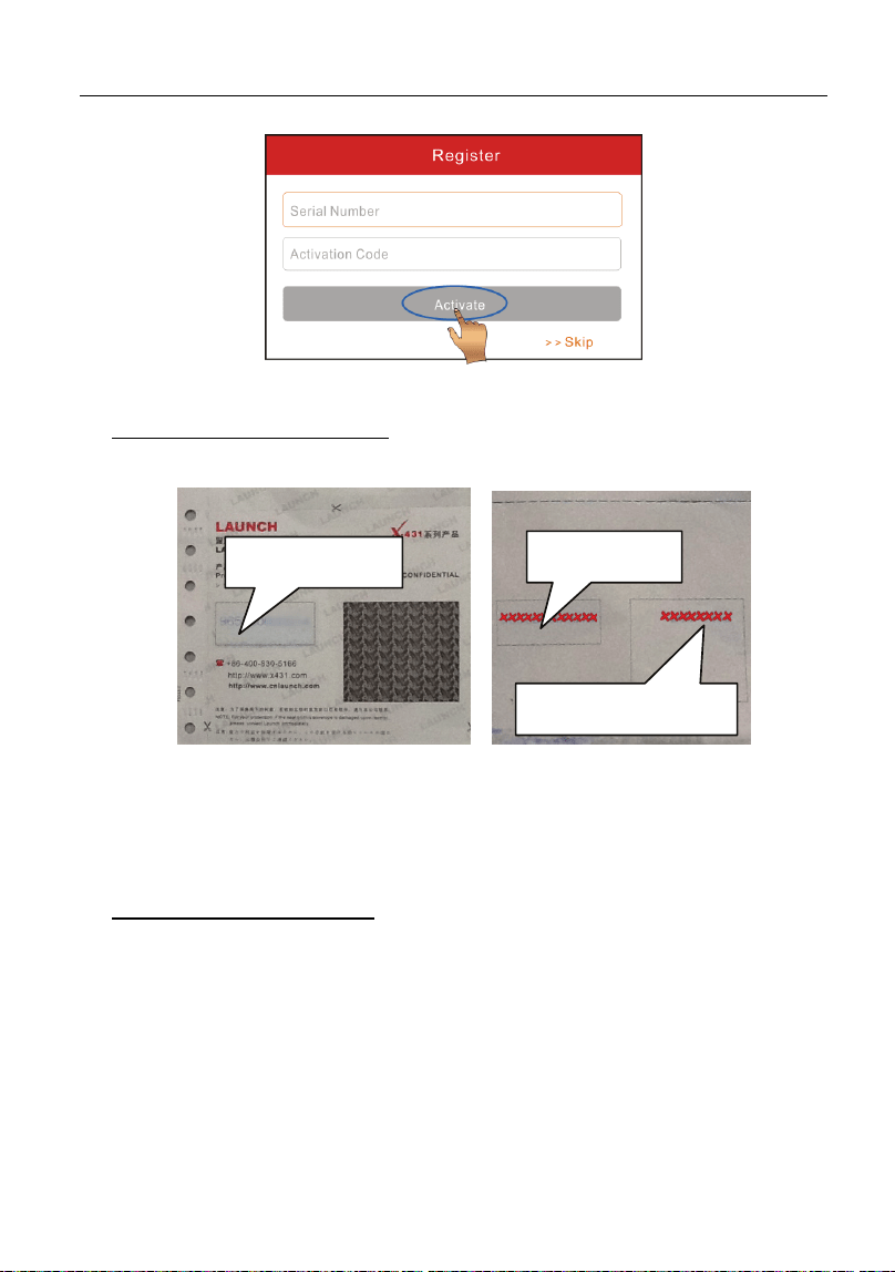
Fig. 4-4
B. Activate the VCI connector: In Fig. 4-4, input the Serial Number and
Activation Code, which can be found in the password envelope.
Fig. 4-5
*Note: To exit and activate it later, tap “Skip”. In this case, you can activate your
connector by tapping “Activate Connector” in “Personal Center”. For details, please
refer to Chapter 9.3 Activate Connector.
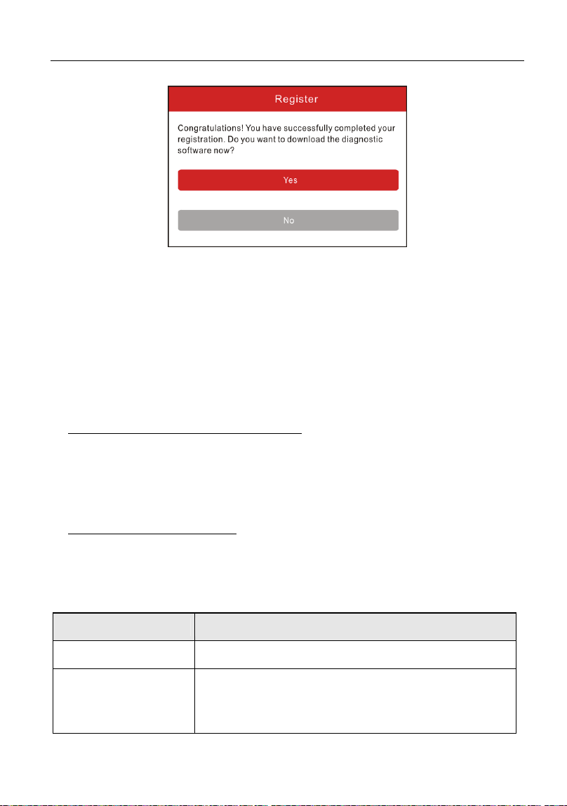
C. Update diagnostic software: Tap “Activate”, a dialog box similar to Fig. 4-6
will appear:
Product SN
Activation code
Product SN
LAUNCH Getting Started & Connections
15
Fig. 4-6
To download the diagnostic software, tap “Yes” to enter the software download
page. Tap “No” to download it later.
On the download page, tap “Update” to start downloading. It may take several
minutes to finish it, please be patient to wait. To pause downloading, tap “Pause”.
To resume it, tap “Continue”.
Once download is complete, the system will install the software package
automatically.
2. If you have registered to be a member, input your name and password, and
then tap the “Login” button to enter the main menu screen directly.
*Note: The tablet has an auto-save function. Once the username and password are
correctly entered, the system will automatically store it. Next time you login the system,
you will not be asked to input the account manually.
3. If you forgot the password, tap “Retrieve Password”, and then follow the
on-screen instructions to retrieve it.
4.2.2 Job menu
It mainly includes the following items:
Name Description
Diagnose
Configures the tablet to operate as a diagnostic tool.
Special Function
To perform some maintenance items, including
electronic throttle position reset, ABS bleeding, oil
lamp reset etc.

LAUNCH Getting Started & Connections
16
Feedback
This option allows you to feed back the diagnostic
reports/software bugs to us for troubleshooting and
analysis.
Software Upgrade
To update vehicle diagnostic software.
Maintenance Help
To browse the FAQ, Quick Start Guide, User Manual
and How-To videos.
Personal Center
To manage, activate your VCI connector, diagnostic
report or personal information etc.
4.3 Connections
4.3.1 Preparation
Normal testing conditions
y
Turn on the vehicle ignition key.
y
Vehicle battery voltage range should be 9-18 Volts.
y
Throttle should be in a closed position.
Select the VCI connector
If the tool is testing vehicles equipped with universal OBD II diagnostic socket,
please use the included VCI connector (For vehicles with non-OBD II diagnostic
socket, a non-16 pin connector is required).
4.3.2 DLC location
The DLC (Data Link Connector) is typically a standard 16-pin connector where
diagnostic tools interface with a vehicle’s on-board control modules. The DLC is
usually located 12 inches from the center of the instrument panel, under or
around the driver’s side for most vehicles. See Fig. 4-7 for DLC location of
different vehicles. If DLC is not located under dashboard, a label should be there
telling location. For some Asian and European vehicles, the DLC is located
behind the ashtray and the ashtray must be removed to access the connector. If
the DLC cannot be found, refer to the vehicle’s service manual.

LAUNCH Getting Started & Connections
17
Fig. 4-7
4.3.3 Vehicle connection
The method used to connect the VCI connector to a vehicle’s DLC depends on
the vehicle’s configuration as follows:
y
A vehicle equipped with an OBD II management system supplies both
communication and 12V power through a standardized DLC.
y
A vehicle not equipped with an OBD II management system supplies
communication through a DLC connection, and in some cases supplies 12V
power through the cigarette lighter receptacle or a connection to the vehicle
battery.
Follow the steps mentioned below to connect OBD II vehicle:
1. Locate vehicle’s DLC.
2. Plug the VCI connector into the vehicle’s DLC (It is suggested to use the
OBD II extension cable to connect the VCI connector and DLC socket).
3. Choose one of the two ways to obtain power from:
A. Power adaptor: Connect one end of the included power adaptor to
charging port of the tablet, and the other end to AC outlet.
B. Internal battery pack
For non-OBDII vehicle, proceed as follows:
1. Locate vehicle’s DLC.
2. Select the corresponding non-16pin connector.
3. Plug the non-16pin end of the connector into the DLC, then connect the other
end to the OBD I adaptor, and then tighten the captive screws.
4. Connect the other end of the adaptor to the included VCI connector.
LAUNCH Getting Started & Connections
18
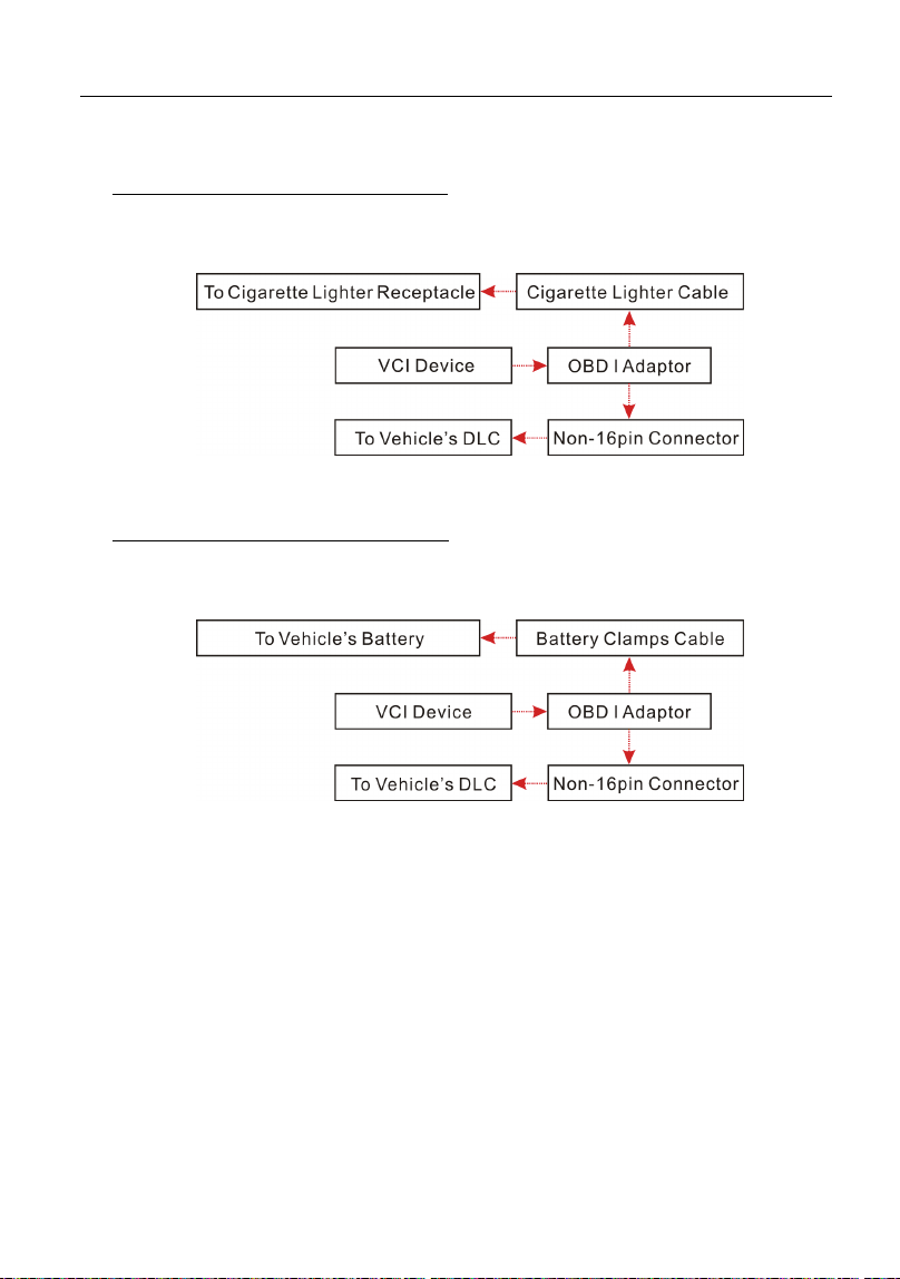
5. To supply power to OBD I adaptor from:
A. Cigarette Lighter Cable (optional): Connect one end of the cigarette lighter
cable to vehicle’s cigarette lighter receptacle, and the other end to the power
jack of OBD I adaptor.
Fig. 4-8
B. Battery Clamps Cable (optional): Connect one end of the battery clamps
cable to vehicle’s battery, and the other end to the power jack of OBD I
adaptor.
Fig. 4-9
4.4 Communication Setup
1. Go to the Bluetooth setting screen by tapping “Settings” -> “Bluetooth”, slide
the Bluetooth switch to ON and the tablet starts searching for all available
Bluetooth device.
2. Tap the desired VCI to pair and match. By default, the Bluetooth ID of the VCI
is 98********00 (where ******** stands for 8 digits).
3. If the Bluetooth pair request pops up on the screen, enter the request pin
code (default code: 0000 or 1234).
4. Once the VCI is paired with the tablet, it will be shown under the paired device
tab.
LAUNCH Start Diagnostics
19
5 Start Diagnostics
Follow the steps mentioned below to start a new diagnostic session.
Tap “Diagnose”, and then tap a corresponding diagnostic software logo.
Take Demo as an example to demonstrate how to diagnose a vehicle.
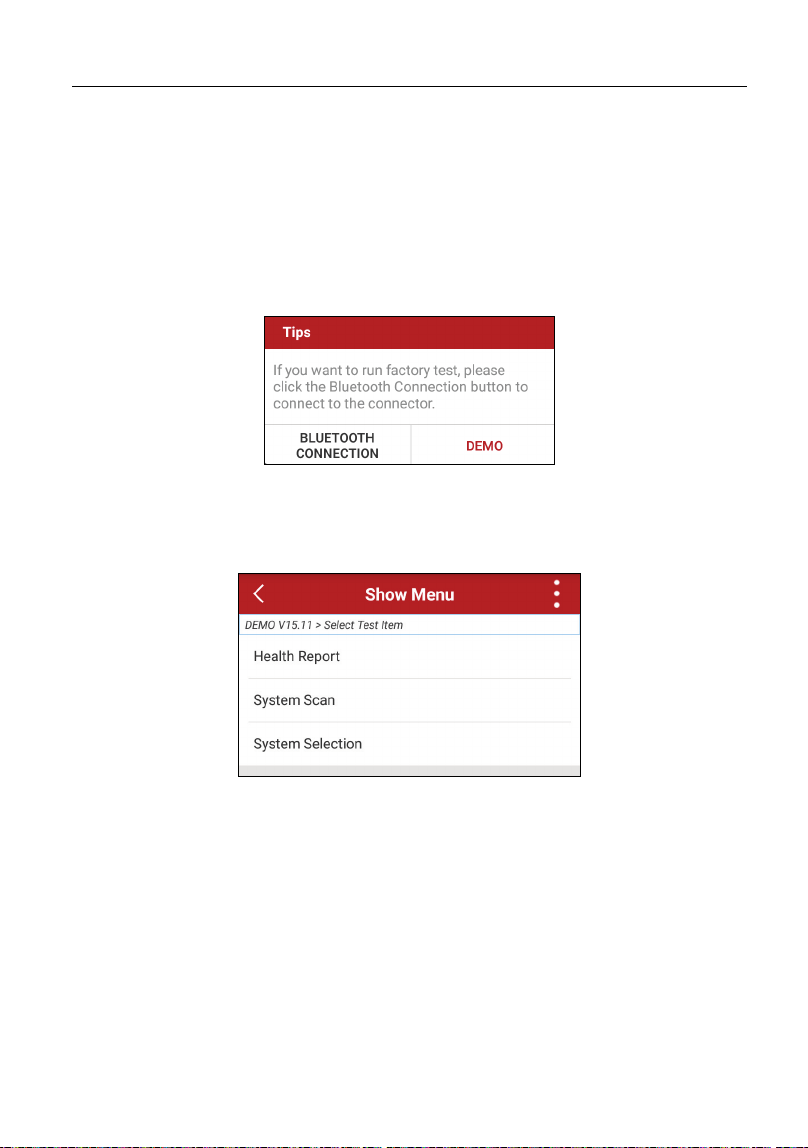
1). Tap the “DEMO”, a screen similar to the following appears:
Fig. 5-1
2). Tap “Demo” to ignore the connection and jump to the test item selection
screen
(*Note: No connection is required for DEMO program).
Fig. 5-2
5.1 Health Report (Quick Test)
This function varies from vehicle to vehicle. It enables you to quickly access all
the electronic control units of the vehicle and generate a detailed report about
vehicle health.
*Note: Diagnostic Trouble Codes or Fault Codes can be used to identify which engine
systems or components that are malfunctioning. Never replace a part based only on the
DTC definition. Retrieving and using DTCs for troubleshooting vehicle operation is
only one part of an overall diagnostic strategy. Follow testing procedures (in vehicle’s
LAUNCH Start Diagnostics
20
service manual), instructions and flowcharts to confirm the locations of the problem.
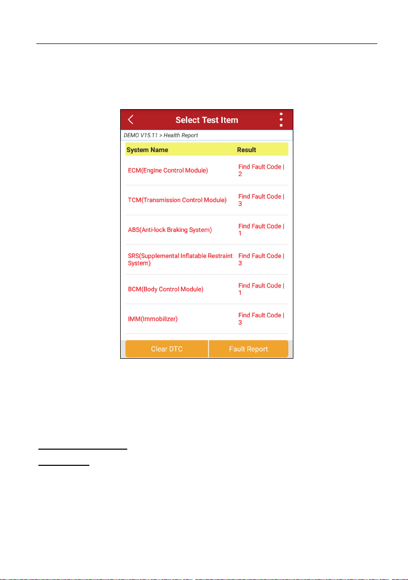
Tap “Health Report”, the system start scanning the ECUs. Once the scanning is
complete, a screen similar to the following appears:
Fig. 5-3
In Fig. 5-3, the tested system with fault code appears in red and the system with
OK displays in black (normally).
Tap the desired system to enter the test function selection page. For detailed
operations on test function, please refer to Chapter 5.3.
On-screen Buttons:
Clear DTC:
Tap to clear the existing diagnostic trouble codes. See Chapter
5.1.2.
*Note: Clearing DTCs does not fix the problem(s) that caused the code(s) to be set. If
proper repairs to correct the problem that caused the code(s) to be set are not made, the
code(s) will appear again and the check engine light will illuminate as soon as the
problem that cause the DTC to set manifests itself.
LAUNCH Start Diagnostics
21
Fault Report:
Tap to view the health report in details. See Chapter 5.1.1.
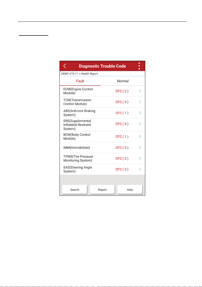
5.1.1 View fault report
This function allows you to view the health report in details.
Fig. 5-4
In Fig. 5-4:
The systems that have been found OK are displayed in black under the Normal
tab.
The tested systems with faults are listed under the Fault tab and the number of
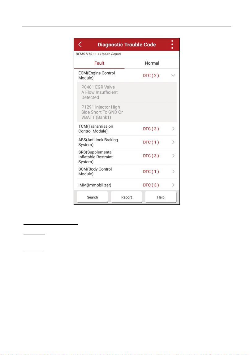
DTC is displayed in red next to the system. Tap > to view the detailed DTC
information of the current system.
LAUNCH Start Diagnostics
22
Fig. 5-5
On-screen Buttons:
Search:
Highlight a certain DTC item, and then tap it to launch the browser to
search for more detailed information about the selected DTC online.
Report:
To save the current data in text format.
All reports are saved under the tab
“Report” in “My Report” from “Personal Center” menu. For details on report
operations, please refer to Chapter 9.1 “My Report”.
5.1.2 Clear DTC
This function lets you clear the existing diagnostic trouble codes in health report.
Tap “Clear DTC”, a confirmation dialog box appears. Tap “Yes” to clear all the
diagnostic trouble codes. Tap “No” to abort it.
LAUNCH Start Diagnostics
23
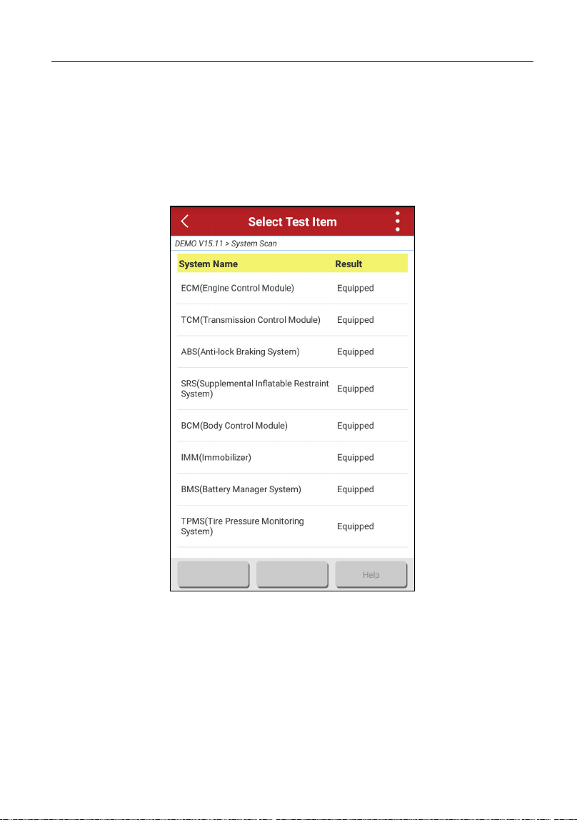
5.2 System Scan
This option allows you to quickly scan which systems are installed on the
vehicle.
In Fig. 5-2, tap “System Scan”, the system start scanning the systems. Once the
scanning is complete, the screen will display the result. See Fig. 5-6.
Fig. 5-6
In Fig. 5-3, tap the desired system to advance to the test function selection page.
For detailed operations on test function, please refer to Chapter 5.3.
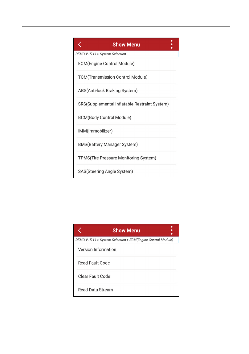
5.3 System Selection
This option allows you manually select the test system and function step by step.
In Fig. 5-2, tap “System Selection”, the screen displays as follows:
LAUNCH Start Diagnostics
24
Fig. 5-7
Swipe the screen from the bottom to view the vehicle system on the next page.
Tap the desired system (take “ECM” for example) to jump to the test function
page.
Fig. 5-8
*Note: Different vehicle has different diagnostic menus.
LAUNCH Start Diagnostics
25
5.3.1 Version Information
This function is used to read the version information of system mode, vehicle
VIN, software and ECU.
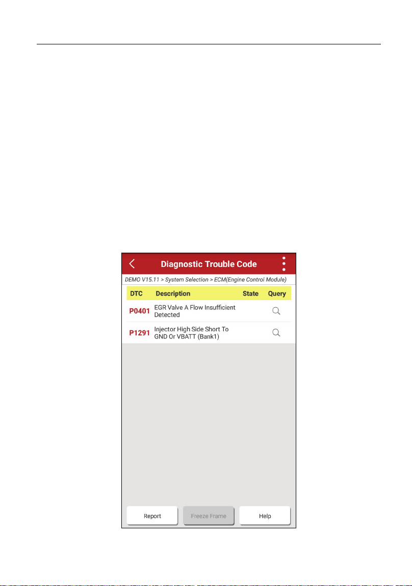
5.3.2 Read Fault Code
This function displays the detailed information of DTC records retrieved from the
vehicle’s control system.
*Note: Retrieving and using DTCs for troubleshooting vehicle operation is only one
part of an overall diagnostic strategy. Never replace a part based only on the DTC
definition. Each DTC has a set of testing procedures, instructions and flow charts that
must be followed to confirm the location of the problem. This information can be found
in the vehicle’s service manual.
In Fig. 5-8, tap “Read DTC”, the screen will display the diagnostic result.
Fig. 5-9

LAUNCH Start Diagnostics
26
On-screen Buttons:
:
Highlight a certain DTC item, and then tap it to search for more information
about the selected DTC online.
Report:
To save the current data in text format.
All reports are saved under the tab
“Diagnostic Report” in “My Report” from “Personal Center” menu. For details on
report operations, please refer to Chapter 9.1 “My Report”.
Freeze Frame:
When an emission-related fault occurs, certain vehicle conditions are
recorded by the on-board computer
. This information is referred to as freeze frame
data. Freeze frame data includes a snapshot of critical parameter values at the
time the DTC is set.
5.3.3 Clear Fault Code
After reading the retrieved codes from the vehicle and certain repairs have been
carried out, you can use this function to erase the codes from the vehicle. Before
performing this function, please be sure the vehicle’s ignition key is in the ON
position with the engine off.
Clearing DTCs does not fix the problem(s) that caused the code(s) to be set. If
proper repairs to correct the problem that caused the code(s) to be set are not
made, the code(s) will appear again and the check engine light will illuminate as
soon as the problem that cause the DTC to set manifests itself.
In Fig. 5-8, tap “Clear Fault Code”, a confirmation dialog box pops up on the
screen. Tap “Yes”, the system will automatically delete the currently existing
trouble code.
*Note: After clearing, you should retrieve trouble codes once more or turn ignition on
and retrieve codes again. If there are still some trouble codes in the system, please
troubleshoot the code using a factory diagnosis guide, then clear the code and recheck.
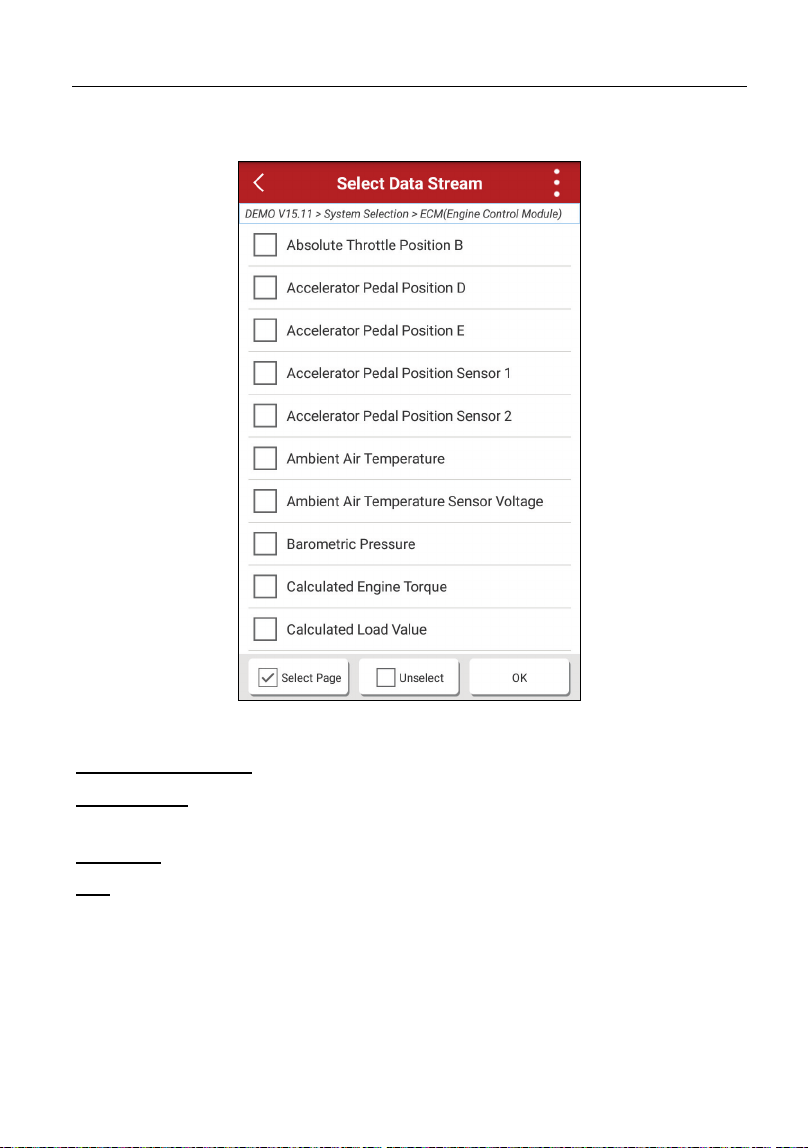
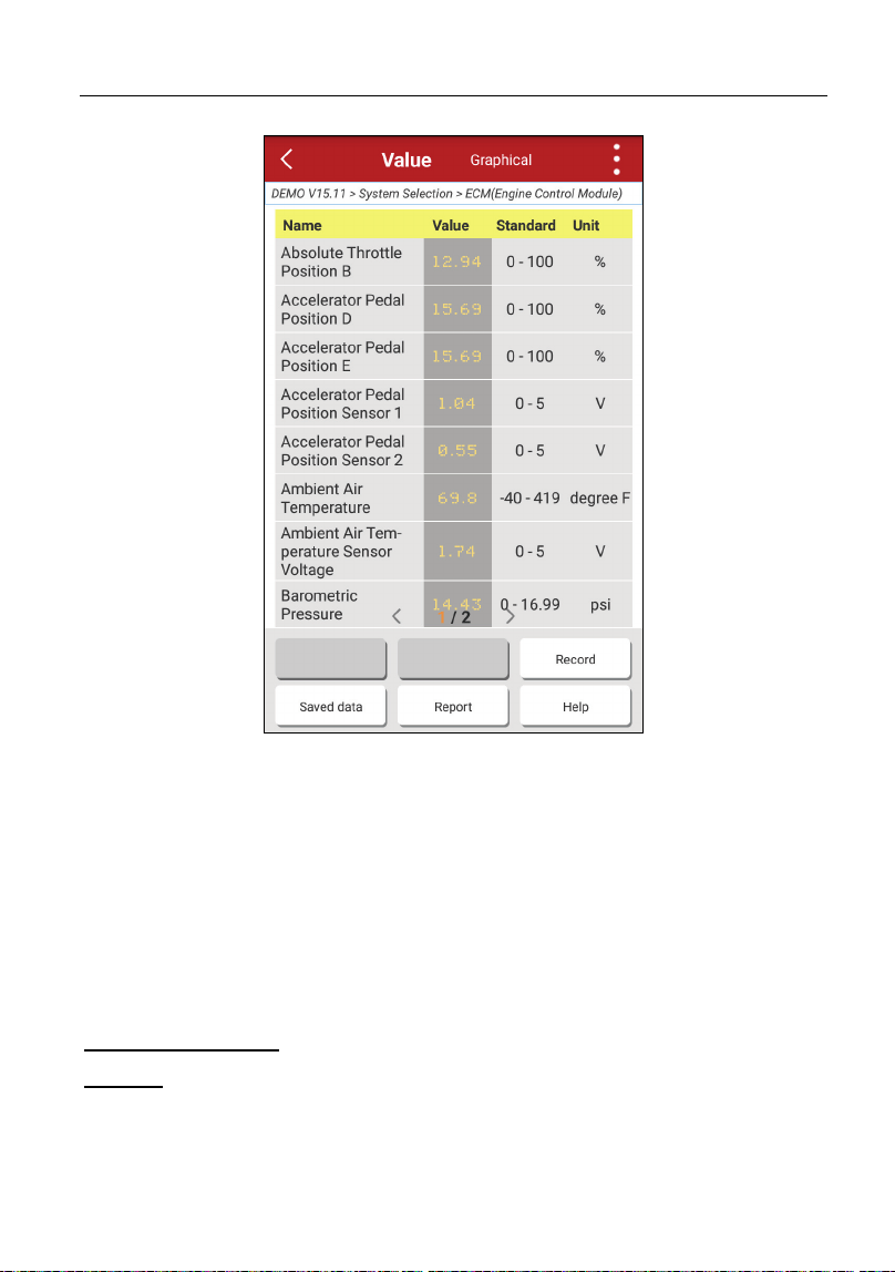
5.3.4 Read Data Stream
This option lets you view and capture (record) real-time Live Data. This data
including current operating status for parameters and/or sensor information can
provide insight on overall vehicle performance. It can also be used to guide
vehicle repair.
*Note: If you must drive the vehicle in order to perform a troubleshooting procedure,
ALWAYS have a second person help you. Trying to drive and operate the diagnostic
tool at the same time is dangerous, and could cause a serious traffic accident.
LAUNCH Start Diagnostics
27
In Fig. 5-8, tap “Read Data Stream”, the system will display data stream items.
Fig. 5-10
On-screen Buttons:
Select Page:
Tap it to select all items of the current page. To select certain data
stream item, just check the box before the item name.
Unselect:
Tap it to deselect all data stream items.
OK:
Tap it to confirm and jump to the next step.
After selecting the desired items, tap “Confirm” to enter the data stream reading
page.
LAUNCH Start Diagnostics
28
Fig. 5-11
*Notes:
1.
If the value of the data stream item is out of the range of the standard (reference)
value, the whole line will display in red. If it complies with the reference value, it
displays in black (normal mode).
2.
The indicator 1/X shown on the bottom of the screen stands for the current page
/total page number. Swipe the screen from the right/left to advance/return to the
next/previous page.
On-screen Buttons:
Record:
Tap to start recording diagnostic data for future playback and analysis.
The saved file follows the naming rule: It begins with vehicle type, and then the
record starting time and ends with .x431 (To differentiate between files, please
configure the accurate system time). The file is stored in “My Report” under
LAUNCH Start Diagnostics
29
“
Personal Center
” menu. For details on playback operations, please refer to
Chapter 9.1 “My Report”.
To stop reading the data stream, tap
before the recording progress bar.
Saved data:
Tap to access to “My Reports”.
Report:
Tap to save the current waveform as a diagnostic record.
There are 3 types of display modes available for data viewing, allowing you to
view various types of parameters in the most suitable way.
9
Value – this is the default mode which displays the parameters in texts and
shows in list format.
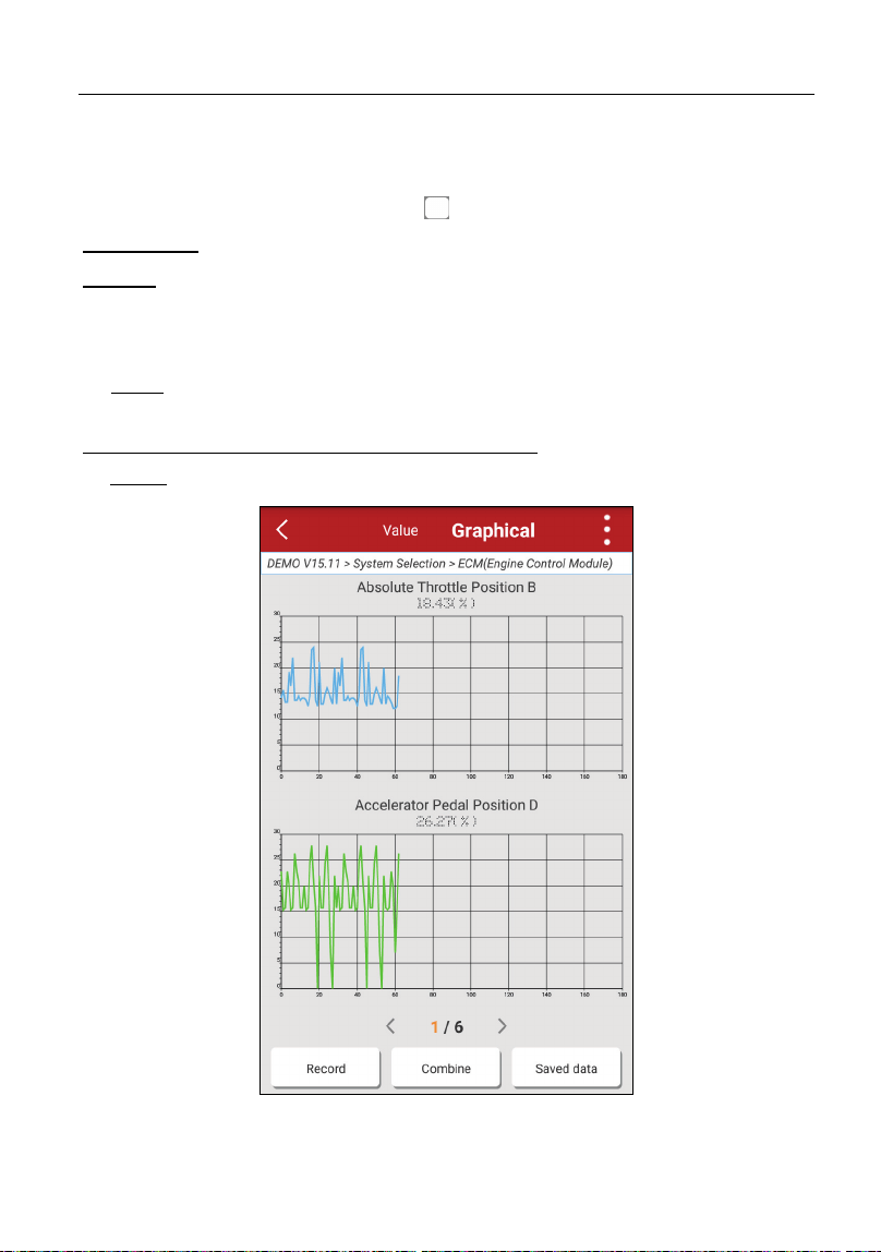
The following display modes are under Graph tab.
9
Graph – displays the parameters in waveform graphs. Refer to Fig. 5-12.
Fig. 5-12
LAUNCH Start Diagnostics
30
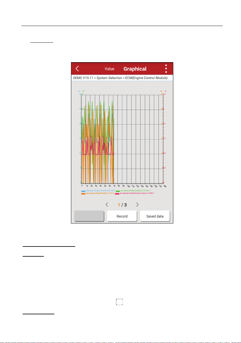
9
Combine – this option is mostly used in graph merge status for data
comparison.
In this case, different items are marked in different colors. See
Fig. 5-13.
Fig. 5-13
On-screen Buttons:
Record:
Tap to start recording diagnostic data for future playback and analysis.
The saved file follows the naming rule: It begins with vehicle type, and then the
record starting time and ends with .x431 (To differentiate between files, please
configure the accurate system time). The file is stored in “My Report” under
“
Personal Center
” menu. For details on playback operations, please refer to
Chapter 9.1 “My Report”.
To stop reading the data stream, tap
before the recording progress bar.
Saved data:
Tap to access to “My reports”.
LAUNCH Start Diagnostics
31
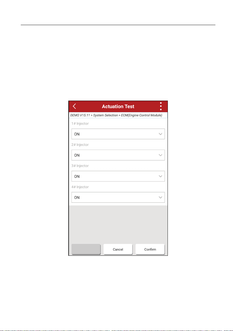
5.3.5 Actuation Test
This option is used to access vehicle-specific subsystem and component tests.
Available test vary by vehicle manufacturer, year, and model.
During the actuation test, the Phoenix Pro handset outputs commands to the
ECU in order to drive the actuators, and then determines the integrity of the
system or parts by reading the ECU data, or by monitoring the operation of the
actuators, such as switching a injector between two operating states.
In Fig. 5-8, tap “Actuation Test”, the system will display as follows:
Fig. 5-14
Simply follow the on-screen instructions and make appropriate selections to
complete the test. Each time when an operation is successfully executed,
“Completed” displays.
LAUNCH Start Diagnostics
32
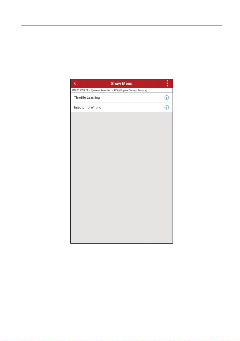
5.3.6 Special Function
In addition to amazing & powerful diagnostic function, the tool also features
various reset functions, which varies from vehicle to vehicle. In this case, just
choose the desired special functions to perform. For detailed information, please
refer to Chapter 6 Reset.
Fig. 5-15

LAUNCH Special Functions
33
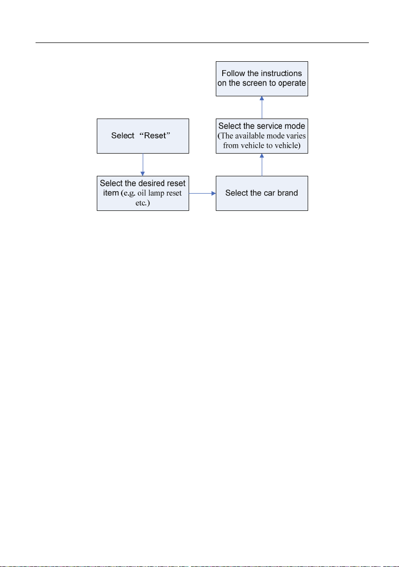
6 Reset
Except that the special functions can be performed from the diagnostic menus
(See Chapter 5.3.6) of certain vehicle model, this module provides an easy dial to
quickly access the special functions.
The most commonly performed service functions contain:
y Oil Reset Service
y Electronic Parking Brake Reset
y Steering Angle Calibration
y ABS Bleeding
y TPMS (Tire Pressure Monitor System) Reset
y Gear Learning
y IMMO Service
y Injector Coding
y Battery Maintenance System
y Diesel Particulate Filter (DPF) Regeneration
y Electronic Throttle Position Reset
There are two methods to reset service lamp: Manual reset or Auto reset. Auto
reset follows the principle of sending command from the tool to vehicle’s ECU to
do resetting. While using manual reset, users just follow the on-screen
instructions to select appropriate execution options, enter correct data or values,
and perform necessary actions, the system will guide you through the complete
performance for various service operations.
LAUNCH Special Functions
34
Figure 6-1
6.1 Oil Reset Service
This function allows you to perform reset for the engine oil life system, which
calculates an optimal oil life change interval depending on the vehicle driving
conditions and climate.
This function can be performed in the following cases:
1. If the service lamp is on, you must provide service for the car. After service,
you need to reset the driving mileage or driving time so that the service lamp
turns off and the system enables the new service cycle.
2. After changing engine oil or electric appliances that monitor oil life, you need
to reset the service lamp.
6.2 Electronic Parking Brake Reset
1. If the brake pad wears the brake pad sense line, the brake pad sense line
sends a signal sense line to the on-board computer to replace the brake pad.
After replacing the brake pad, you must reset the brake pad. Otherwise, the
car alarms.
2. Reset must be performed in the following cases:
a) The brake pad and brake pad wear sensor are replaced.
b) The brake pad indicator lamp is on.
c) The brake pad sensor circuit is short, which is recovered.

LAUNCH Special Functions
35
d) The servo motor is replaced.
6.3 Steering Angle Calibration
To reset the steering angle, first find the relative zero point position for the car to
drive in straight line. Taking this position as reference, the ECU can calculate the
accurate angle for left and right steering.
After replacing the steering angle position sensor, replacing steering mechanical
parts (such as steering gearbox, steering column, end tie rod, steering knuckle),
performing four-wheel alignment, or recovering car body, you must reset the
steering angle.
6.4 ABS Bleeding
This function allows you to perform various bi-directional tests to check the
operating conditions of Anti-lock Braking System (ABS).
1. When the ABS contains air, the ABS bleeding function must be performed to
bleed the brake system to restore ABS brake sensitivity.
2. If the ABS computer, ABS pump, brake master cylinder, brake cylinder, brake
line, or brake fluid is replaced, the ABS bleeding function must be performed
to bleed the ABS.
6.5 Tire Pressure Monitor System Reset
This function allows you to quickly look up the tire sensor IDs from the vehicle’s
ECU, as well as to perform TPMS replacement and sensor test.
1. After the tire pressure MIL turns on and maintenance is performed, the tire
pressure resetting function must be performed to reset tire pressure and turn
off the tire pressure MIL.
2. Tire pressure resetting must be performed after maintenance is performed in
the following cases: tire pressure is too low, tire leaks, tire pressure
monitoring device is replaced or installed, tire is replaced, tire pressure sensor
is damaged, and tire is replaced for the car with tire pressure monitoring
function.
6.6 Gear Learning
The crankshaft position sensor learns crankshaft tooth machining tolerance and

LAUNCH Special Functions
36
saves to the computer to more accurately diagnose engine misfires. If tooth
learning is not performed for a car equipped with Delphi engine, the MIL turns on
after the engine is started. The diagnostic device detects the DTC P1336 'tooth
not learned'. In this case, you must use the diagnostic device to perform tooth
learning for the car. After tooth learning is successful, the MIL turns off.
After the engine ECU, crankshaft position sensor, or crankshaft flywheel is
replaced, or the DTC 'tooth not learned' is present, tooth learning must be
performed.
6.7 IMMO Service
An immobilizer is an anti-theft mechanism that prevents a vehicle’s engine from
starting unless the correct ignition key or other device is present. Most new
vehicles have an immobilizer as standard equipment. An important advantage of
this system is that it doesn’t require the car owner to activate it since it operates
automatically. An immobilizer is considered as providing much more effective
anti-theft protection than an audible alarm alone.
As an anti-theft device, an immobilizer disables one of the systems needed to
start a car’s engine, usually the ignition or the fuel supply. This is accomplished
by radio frequency identification between a transponder in the ignition key and a
device called a radio frequency reader in the steering column. When the key is
placed in the ignition, the transponder sends a signal with a unique identification
code to the reader, which relays it to a receiver in the vehicle’s computer control
module. If the code is correct, the computer allows the fuel supply and ignition
systems to operate and start the car. If the code is incorrect or absent, the
computer disables the system, and the car will be unable to start until the correct
key is placed in the ignition.
To prevent the car being used by unauthorized keys, the anti-theft key matching
function must be performed so that the immobilizer control system on the car
identifies and authorizes remote control keys to normally use the car.
When the ignition switch key, ignition switch, combined instrument panel, ECU,
BCM, or remote control battery is replaced, anti-theft key matching must be
performed.
6.8 Injector Coding
Write injector actual code or rewrite code in the ECU to the injector code of the

LAUNCH Special Functions
37
corresponding cylinder so as to more accurately control or correct cylinder
injection quantity.
After the ECU or injector is replaced, injector code of each cylinder must be
confirmed or re-coded so that the cylinder can better identify injectors to
accurately control fuel injection.
6.9 Battery Maintenance System Reset
This function enables you to perform a resetting operation on the monitoring unit
of vehicle battery, in which the original low battery fault information will be
cleared and battery matching will be done.
Battery matching must be performed in the following cases:
a) Main battery is replaced. Battery matching must be performed to clear
original low battery information and prevent the related control module from
detecting false information. If the related control module detects false
information, it will invalidate some electric auxiliary functions, such as
automatic start & stop function, sunroof without one-key trigger function,
power window without automatic function.
b) Battery monitoring sensor. Battery matching is performed to re-match the
control module and motoring sensor to detect battery power usage more
accurately, which can avoid an error message displaying on the instrument
panel.
6.10 Diesel Particulate Filter (DPF) Regeneration
DPF regeneration is used to clear PM (Particulate Matter) from the DPF filter
through continuous combustion oxidation mode (such as high temperature
heating combustion, fuel additive or catalyst reduce PM ignition combustion) to
stabilize the filter performance.
DPF regeneration may be performed in the following cases:
a) The exhaust back pressure sensor is replaced.
b) The PM trap is removed or replaced.
c) The fuel additive nozzle is removed or replaced.
d) The catalytic oxidizer is removed or replaced.
e) The DPF regeneration MIL is on and maintenance is performed.
f) The DPF regeneration control module is replaced.

LAUNCH Special Functions
38
6.11 Electronic Throttle Position Reset
This function enables you to make initial settings to throttle actuators and returns
the “learned” values stored on ECU to the default state. Doing so can accurately
control the actions of regulating throttle (or idle engine) to adjust the amount of
air intake.
LAUNCH Diagnostic Feedback
39
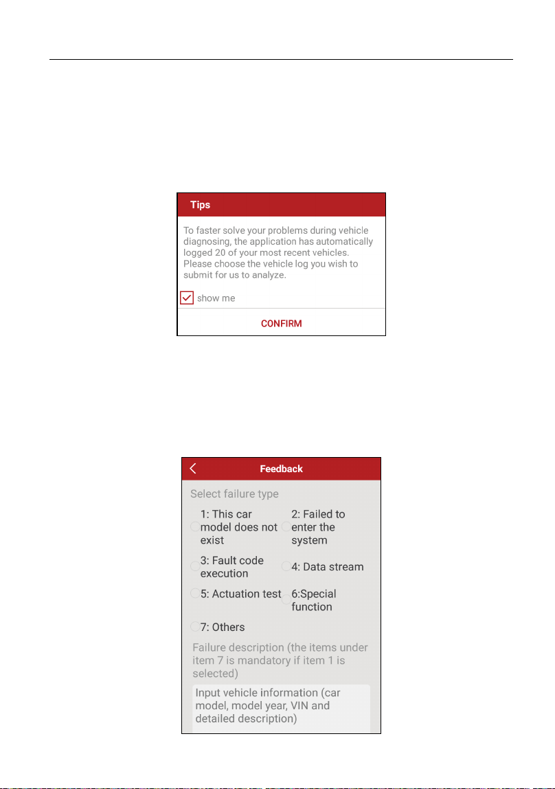
7 Feedback
This item allows you to feedback your diagnostic problems to us for analysis and
troubleshooting.
Tap “Feedback”, a pop-up message will appear:
Fig. 7-1
Tap “CONFIRM” to choose the vehicle diagnostic record page.
A). Tap the desired vehicle to enter the diagnostic log selection page.
Select the check box and tap “Submit”. A screen similar to the following will
appear:

LAUNCH Diagnostic Feedback
40
Fig. 7-2
Check the box before the failure type, fill in the detailed failure description in the
blank text box and telephone or email address. After inputting, tap “Submit
Result” to send it to us.
B). Tap “History”, the diagnostic logs marked with different color indicate the
process status of the diagnostic feedback. Black/Red/Blue means the diagnostic
feedback is fixed/pending/in process respectively.
LAUNCH Software Update
41
8 Software Upgrade
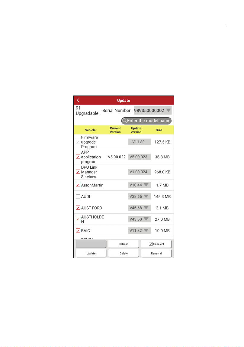
8.1 Update Diagnostic Software & APP
Once a newer diagnostic software version is detected, a prompt message will
pop up on the screen. To keep synchronized with the latest version, tap “Update
now” to enter the update center.
Fig. 8-1
All software is selected by default, tap “Update” to start downloading all software.
To update certain software, input the software name in the model name search
bar to quickly locate it and tap “Update” to download it. Once downloading is
finished, the software package will be installed automatically.
To delete the older version saved on the local storage, select the check box and
then tap “Delete”. Once it is successfully removed, the vehicle logo on the
LAUNCH Software Update
42
diagnostics main menu will disappear at the same time.
*Note: Before update, please make sure the tablet has a strong WLAN connection.
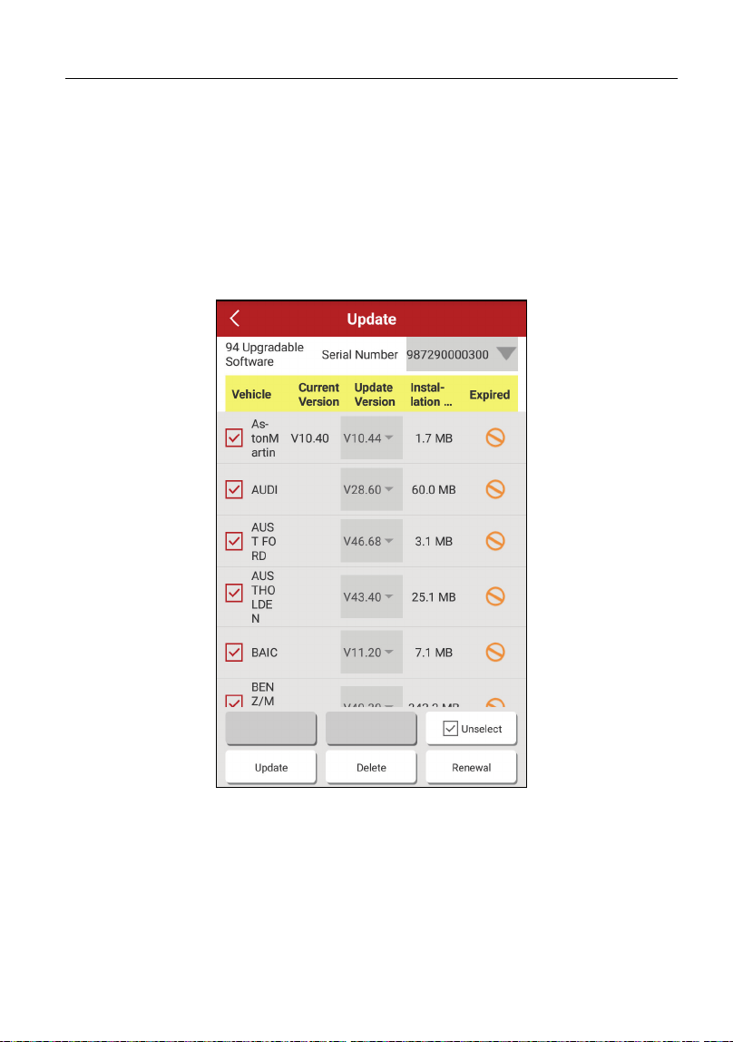
8.2 Renew Subscription
If the software subscription is due or expires, the system will prompt you to
renew your subscription and a “Renew” button will appear on the bottom of the
update page.
Fig. 8-2
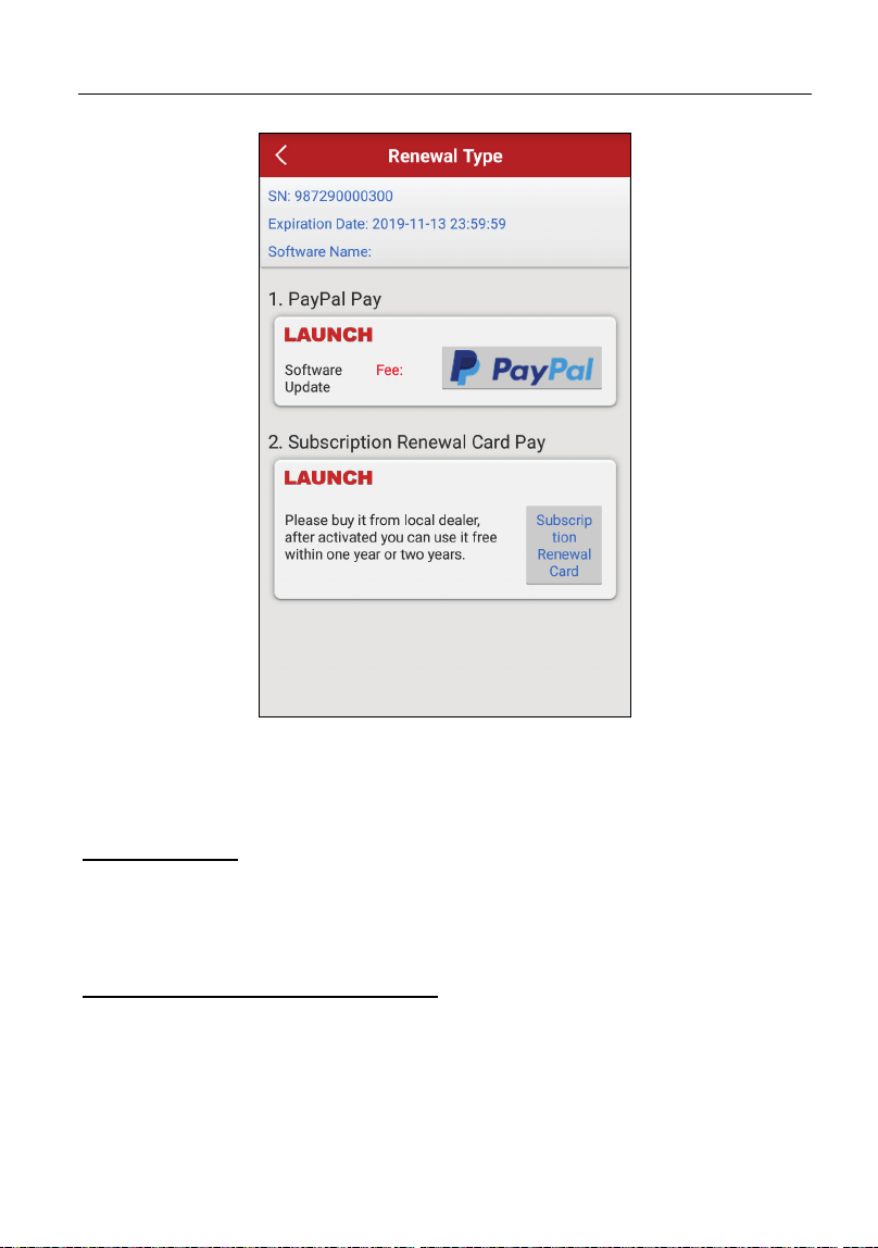
Tap “Renewal” to navigate to the payment screen.
LAUNCH Software Update
43
Fig. 8-3
There are two ways available for you to make payment: PayPal and Subscription
Renewal Card
(*needtobuyitfromthelocaldealerwhereyoupurchasedthetool)
.
A. Using PayPal
1. Select “PayPal”, and then follow the on-screen instructions to finish the
transaction.
2. After payment, go to update center to update the diagnostic software.
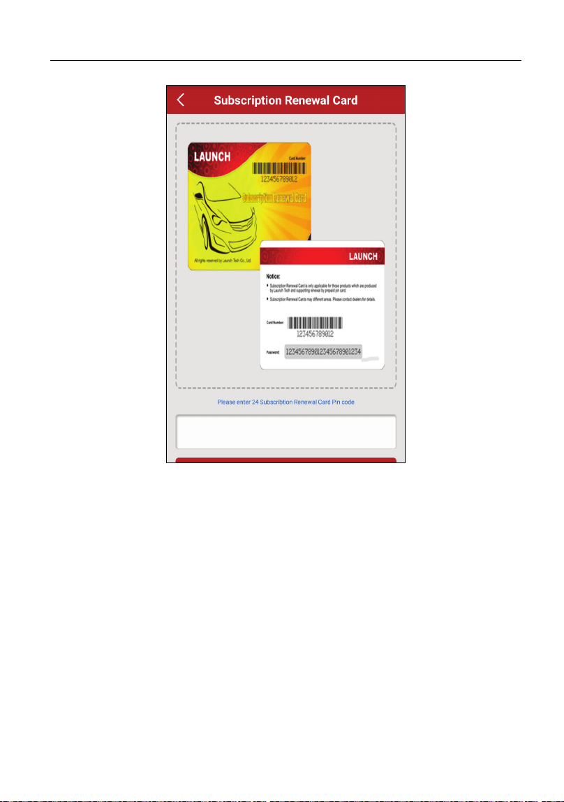
B. Using Subscription Renewal Card
1. Select “Subscription Renewal Card”.
LAUNCH Software Update
44
Fig. 8-4
2. Input the 24-digit pin code of Subscription Renewal Card and then tap
“Submit” to finish the renewal.
3. Go to update center to update the diagnostic software.
LAUNCH Personal Center
45
9 Personal Center
This function allows users to manage the VCI connector and diagnostic reports,
and personal information.
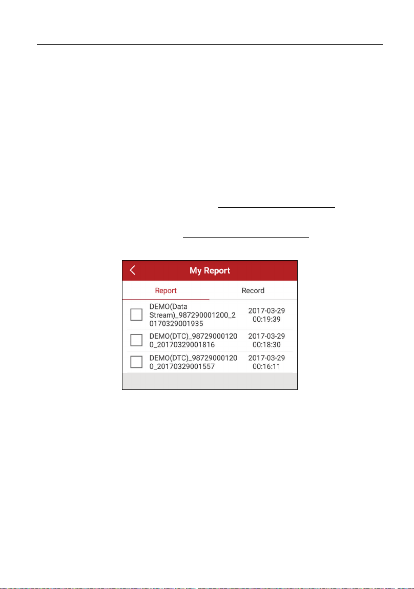
9.1 My Report
This option is used to view the diagnostic report generated in process of vehicle
diagnosis. Additionally, delete, share operations are also supported.
Tap “
My Report
”, there are total 2 options available.
If user records the running parameters while reading data stream, it will be
saved as .x431 file and appear under
Record
tab.
In case the DTC result is saved on Read Trouble Code page, the files will be
listed under
Report
tab.
Fig. 9-1
9.2 My Connector
This option is used to manage all your activated connectors.
If several VCI connectors are activated on this tool, a list of connectors will be
displayed on the screen. Once you choose the connector that belongs to other
account, you have to log out, and then input the right account to continue.
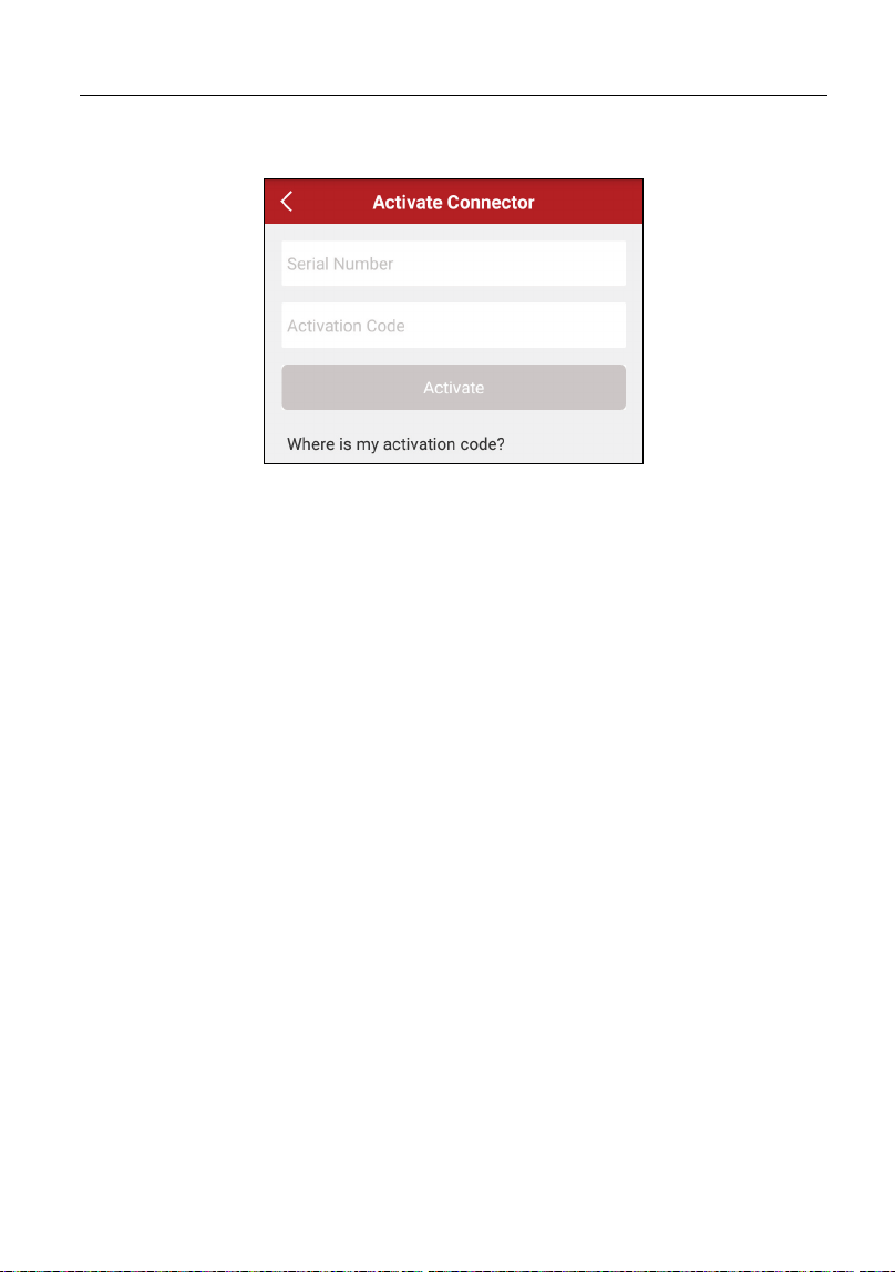
9.3 Activate Connector
If the VCI connector has not been activated during the product registration, or if
you have lost the bound connector and bought another brand-new one, please
LAUNCH Personal Center
46
use this option to activate it.
Fig. 9-2
Input the Serial Number and Activation Code, and then tap “Activate” to activate
it.
*Note: The Serial Number and Activation Code can be found from the password
envelope.
9.4 Firmware Fix
Use this item to upgrade and fix diagnostic firmware. During fixing, please do not
cut power or switch to other interfaces.
9.5 My Order
Use this item to check the historical order information.
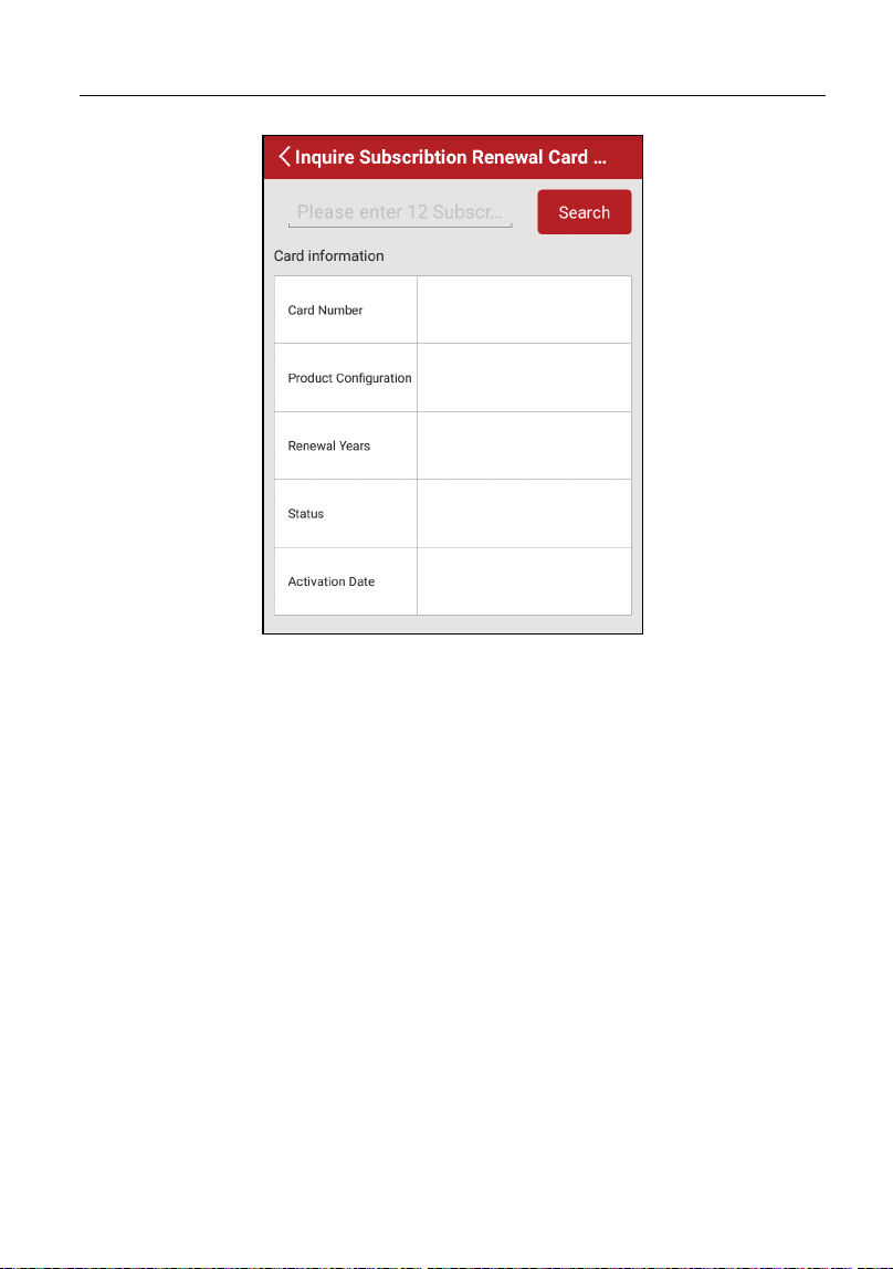
9.6 Inquire Subscription Renewal Card Status
If you renew your subscription with the subscription renewal card, use this option
to check the status of the renewal card.
LAUNCH Personal Center
47
Fig. 9-3
Enter the 12-digit subscription renewal card number, and tap or click “Search” to
check the status. It mainly includes the product configuration, renewal years and
activation date etc.
9.7 Profile
Use this item to view and configure personal information.
9.8 Change password
This item allows you to modify your login password.
9.9 Settings
This function allows users to configure system settings.
9.9.1 Units of Measurement
It is designed to set the measurement unit. Metric System and English System

LAUNCH Personal Center
48
are available.
9.9.2 About
The software version information and disclaimer are included.
9.9.3 Log out
This option allows you to logout the system.
To logout the current user ID, tap “Exit from current account”.

LAUNCH Others
49
10 Others
10.1 Synchronization
You can transfer media files and APK between the PC and tablet.
10.1.1 Connect to PC
1. Use the data cable (optional) to connect the tablet to your PC.
2. Swipe from the top, a message “Connected as a media device” appears.
10.1.2 Run on PC
Perform the following steps:
y Locate the new disc.
y Copy the files.
10.1.3 Install an application
Do the following steps:
1. Tap Settings -> Security, and set the “Unknown sources” to ON, which
allows you to install apps from unknown sources.
2. A dialog box appears on the screen, tap “OK” to confirm.
3. Set the tool as “Connected as a media device”, and copy the APK file from
the PC to the tool.
10.2 Clear Cache
Warning: Doing so clears all browsing records and accounts and enables the tablet
to run smoothly and quickly.
1. Tap Settings -> Apps.
2. Tap
and select “Sort by size” to arrange all applications in size order.
3. Tap certain application, then tap “Clear Cache” to release the space these
cache files are occupied.

LAUNCH FAQ
50
11 FAQ
1. How to save power?
¾ Please turn off the screen while the tool keeps idle.
¾ Set a shorter standby time.
¾ Decrease the brightness of the screen.
¾ If WLAN connection is not required, please turn it off.
¾ Disable GPS function if GPS service is not in use.
2. Communication error with vehicle ECU?
Please confirm:
1. Whether diagnostic connector is correctly connected.
2. Whether ignition switch is ON.
3. If all checks are normal, send vehicle year, make, model and VIN number to
us using Feedback feature.
3. Failed to enter into vehicle ECU system?
Please confirm:
1. Whether the vehicle is equipped with this system.
2. Whether the VCI dongle is correctly connected.
3. Whether ignition switch is ON.
4. If all checks are normal, send vehicle year, make, model and VIN number to
us using Feedback feature.
4. How to reset the tablet?
Warning: Resetting may cause data loss. Before doing so, please make sure
important data and information has been backed up.
Do the following to reset the tablet:
1. Tap “Settings” -> “Back & Reset”.
2. Tap “Factory data reset”.
3. Tap “Reset tablet”.
4. Tap “Clear all data” to start resetting until the tool automatically reboots.

LAUNCH FAQ
51
5. How to download the X-431 Diagun v App after resetting the tablet?
*Note: Before registration, please make sure the network is properly connected.
After the tablet has been successfully reset, follow the steps below to download
the App:
1. Launch the browser and the default official Launch website opens (If a blank
page pops up, just type in www.x431.com in the input bar).
2. Tap “Login”, input the username and password and tap “Log In.”
3. Make sure that the serial number is correct, tap “APP application program”
and tap the Download icon to start downloading.
4. After the download is complete, follow the on-screen instructions to install it.
5. After installation, use the existing username and password to login and go to
update center to download the diagnostic software.
6. What to do if the language of vehicle diagnostic software does not
match the system language?
English is the default system language of the tool. After the system language is
set to the preference language, please go to the update center to download the
vehicle diagnostic software of the corresponding language.
If the downloaded diagnostic software is still displayed in English, it indicates
that the software of the current language is under development.
7. How to activate the VCI?
*Note: Before registration, please make sure the network is properly connected.
If you have activated a VCI device before, but bought a new VCI one due to the
loss or other reasons, please follow the below steps to activate:
1. Tap the application icon on the home screen to launch it.
2. Tap "Personal Center" -> "Activate Connector".
3. Input product S/N and activation code, which can be found from the included
password envelope, then tap "Activate".
4. After activation is complete, go to "Personal Center" -> "My Connector" to
check if the activated VCI is displayed in the list or not. Multiple VCIs can be
bound to one tool. If you intend to use one of the VCIs to diagnose or test a
vehicle, just switch to the corresponding one.

LAUNCH Warranty
52
Warranty
THIS WARRANTY IS EXPRESSLY LIMITED TO PERSONS WHO PURCHASE
LAUNCH PRODUCTS FOR PURPOSES OF RESALE OR USE IN THE
ORDINARY COURSE OF THE BUYER’S BUSINESS.
LAUNCH electronic product is warranted against defects in materials and
workmanship for one year from date of delivery to the user.
This warranty does not cover any part that has been abused, altered, used for a
purpose other than for which it was intended, or used in a manner inconsistent
with instructions regarding use. The exclusive remedy for any automotive meter
found to be defective is repair or replacement, and LAUNCH shall not be liable
for any consequential or incidental damages.
Final determination of defects shall be made by LAUNCH in accordance with
procedures established by LAUNCH. No agent, employee, or representative of
LAUNCH has any authority to bind LAUNCH to any affirmation, representation,
or warranty concerning LAUNCH automotive meters, except as stated herein.
Disclaimer
The above warranty is in lieu of any other warranty, expressed or implied,
including any warranty of merchantability or fitness for a particular purpose.
Purchase Order
Replaceable and optional parts can be ordered directly from your LAUNCH
authorized tool supplier. Your order should include the following information:
Order quantity
Part number
Part name
Customer Service
Any question during the operation, please call +86-755-84557891 or send Email
to our official after-sale service email address: [email protected].
If your unit requires repair service, return it to the manufacturer with a copy of
the sales receipt and a note describing the problem. If the unit is determined to
be in warranty, it will be repaired or replaced at no charge. If the unit is

LAUNCH Warranty
53
determined to be out of warranty, it will be repaired for a nominal service charge
plus return freight. Send the unit pre-paid to:
Attn: Customer Service Department
LAUNCH TECH CO., LTD.
Launch Industrial Park,
North of Wuhe Avenue,
Banxuegang, Bantian,
Longgang, Shenzhen, Guangdong
P.R.China, 518129
Launch website: http://www. cnlaunch.com
http://www.x431.com
Statement:
LAUNCH reserves the rights to make any change to product designs and
specifications without notice. The actual object may differ a little from the
descriptions in the manual in physical appearance, color and configuration. We
have tried our best to make the descriptions and illustrations in the manual as
accurate as possible, and defects are inevitable, if you have any question,
please contact local dealer or after-sale service center of LAUNCH, LAUNCH
does not bear any responsibility arising from misunderstandings.