
INSTALLATION GUIDE
PROFESSIONAL
OS76NPX1 models
COMBINATION STEAM OVEN
INSTALLATION GUIDE
NZ AU

3
SAFETY AND WARNINGS
IMPORTANT!
SAVE THESE INSTRUCTIONS
Installation
WARNING!
Fire Hazard
Do not use adapters, reducers, or branching devices to connect this
appliance to the mains power supply.
Failure to follow this advice may result in overheating, burning, or fire.
WARNING!
Cut Hazard
Take care – some edges are sharp.
Failure to use caution could result in injury or cuts.
WARNING!
Electrical Shock Hazard
Before carrying out any work on the electrical section of the appliance, it
must be disconnected from the mains electricity supply.
Connection to a good earth wiring system is absolutely essential
and mandatory.
Alterations to the domestic wiring system must only be made by a
qualified electrician
Failure to follow this advice may result in electrical shock or death.
●
Do not allow children and animals to stop or linger near the appliance when it is pulled
out of the cabinet.
●
If the installation requires alterations to the domestic electrical system, call a qualified
electrician. The electrician should also check that the socket cable section is suitable
for the electricity drawn by the oven.
●
The oven must be earthed.
●
Installation must comply with your local building and electricity regulations.
●
This appliance must be installed and connected to the mains power supply only by a
suitably qualified person according to these installation instructions and in compliance
with any applicable local building and electricity regulations. Failure to install the
appliance correctly could invalidate any warranty or liability claims.
●
If the power supply cable is damaged, it must be replaced by the manufacturer, its
service agent or similarly qualified person in order to avoid a hazard.
●
A circuit breaker is recommended.
●
Do not use adaptors, reducers or branching devices to connect the oven to the mains
electricity supply, as they can cause overheating and burning.
Electrical requirements
●
Connect oven with copper wire only.
●
Do not cut the conduit.
●
A U.L. listed conduit connector must be provided at the junction box.
●
Do not earth to a gas pipe.
●
Do not have a fuse in the earthed or neutral circuit.
●
Fuse both sides of the line.
●
A time delay fuse or circuit breaker is recommended. If using a time delay fuse, then
fuse both sides of the line.
●
Flexible armored cable from the appliance should be connected directly
to the junction box.
●
Connect directly to the fused disconnect (or circuit breaker box) through flexible,
armored or non-metallic sheathed, copper cable (with earthed wire).
●
If codes permit and a separate earthed wire is used, it is recommended that a
qualified electrician determine that the earthed path and wire gauge are in
accordance with local codes.
IMPORTANT SAFETY INSTRUCTIONS!
To avoid hazard, follow these instructions carefully before installing or using this appliance.
●
Save these instructions for the local inspectors use.
●
Please make this information available to the person installing the appliance – doing
so could reduce your installation costs.
●
This oven is to be installed and connected to the electricity supply only by an
authorised person.
4
Prior to installing your oven, ensure the following:
z
The countertop and oven cavity are square and level, and are the required dimensions.
z
The installation will comply with all clearance requirements and applicable standards
and regulations.
z
The isolating switch will be easily accessible to the customer with the oven installed.
z
The electrician provides sufficient free length of power supply cable to reach from the
bottom rear of the cavity to at least 1.5m in front of the bottom edge of the opening.
z
The cable may enter the cavity from the side, top or bottom, but top entry must be at the
rear of the cavity.
z
The oven connection socket (if fitted) is outside the cavity if the oven is flush to the
rear wall.
z
The oven will rest on a surface that can support its weight.
z
The height from the floor suits the customer.
z
You consult local building authorities and by-laws if in doubt regarding installation.
WARNING!
Some environmental factors and cooking habits can cause condensation in and around
the oven during use. To protect surrounding cabinetry from possible damage caused by
frequent or excessive condensation, we recommend moisture-proofing the oven cavity.
During installation, please ensure the following:
z
The oven door(s) can open fully without obstruction.
z
The power supply cable does not touch any hot metal parts.
z
The isolating switch is easily accessible to the customer with the oven installed.
z
You complete the ‘Final checklist’ at the end of the installation.
z
If, after following the instructions given, correct performance cannot be achieved, please
contact your nearest Fisher & Paykel Service Centre, Customer Care, or contact us through
our local website listed at the end of this document.
WARNING!
Take extra care not to damage the lower trim of the oven during installation. The
trim is important for correct air circulation and allows the door to open and close
without obstruction.
The manufacturer does not accept any responsibility for damage resulting from
incorrect installation.
●
The oven can be installed under a cooktop, in a column, or combined with the companion
warmer drawer or coffee maker.
●
The cabinet material must be able to withstand heat.
●
The oven must be centered within the walls of the cabinet and fixed with the screws that
are provided.
z
Keep all packing materials until the unit has been inspected.
z
Inspect the product to ensure there is no shipping damage. If any damage is detected
contact the dealer or retailer you bought the product from to report the damage.
z
Fisher & Paykel is not responsible for shipping damage.
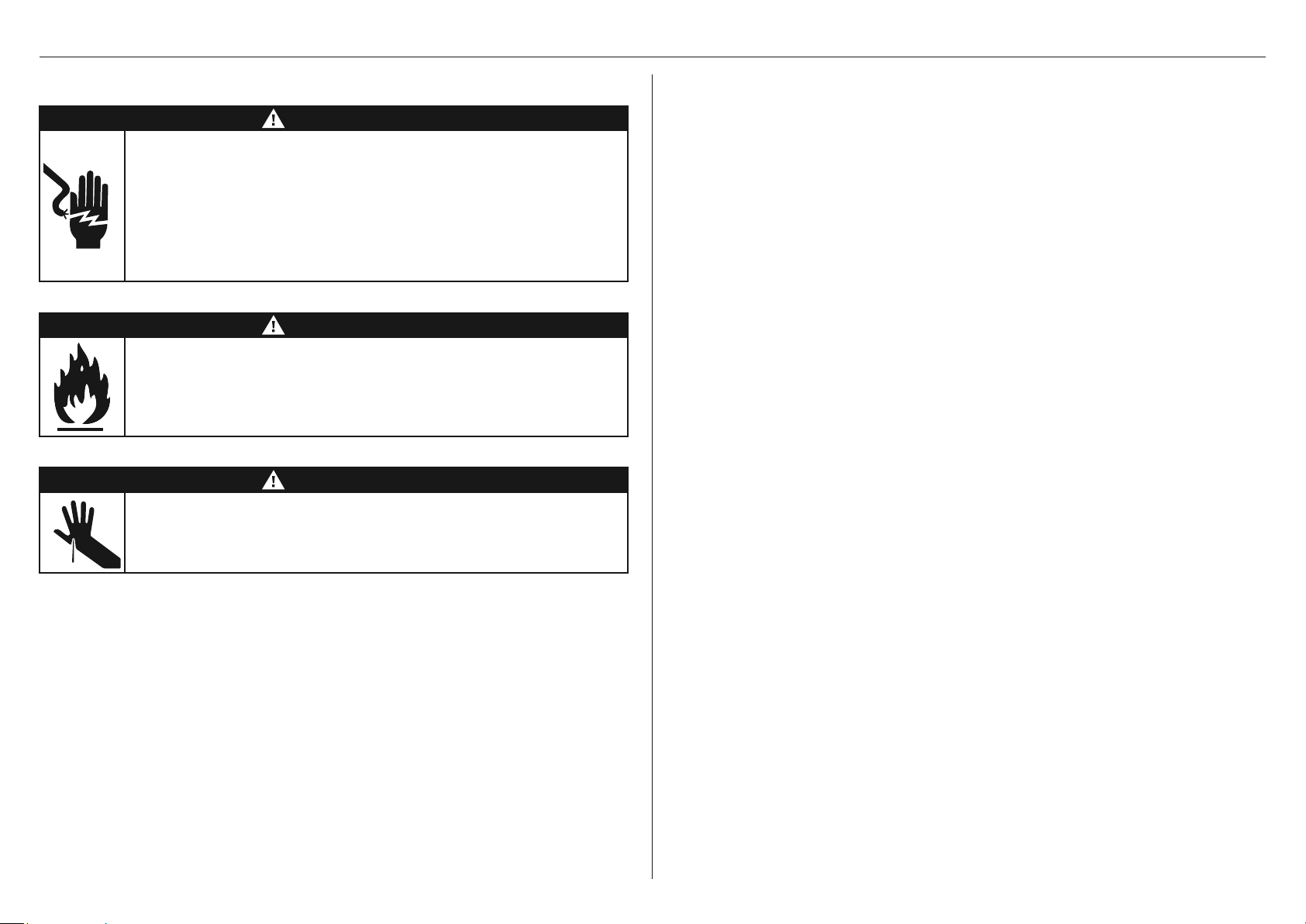
Supplied
Mounting
screws (2)
Mounting
washers (2)
Not supplied
Crosshead
screwdriver
Power drill Scissors
Lower trim (1) Lower trim
screws (4)
PRIOR TO INSTALLATION
DURING INSTALLATION
PARTS SUPPLIED
TOOLS REQUIRED
COMPONENTS REQUIREDINSTALLATION CONSIDERATIONS
5
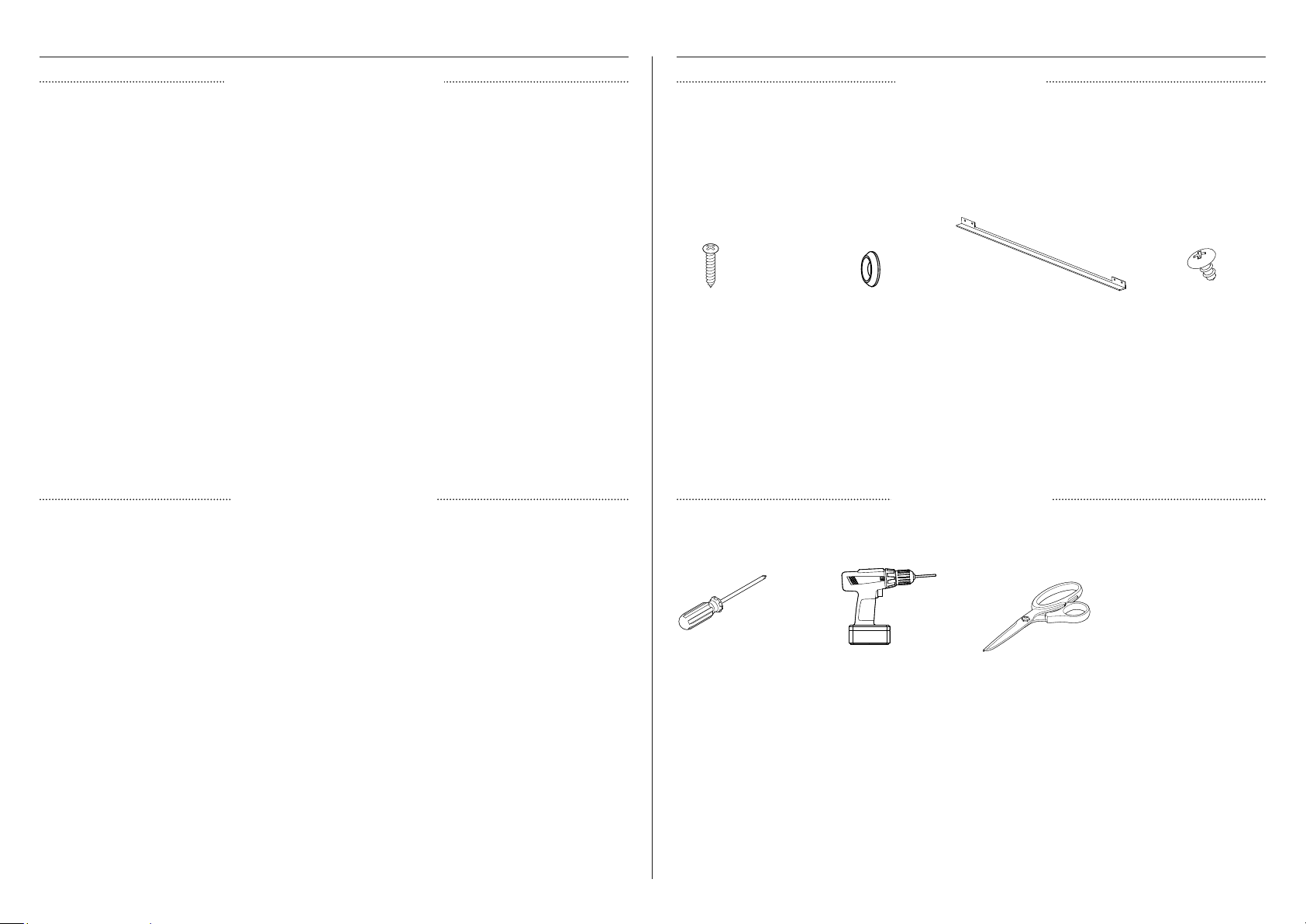
PRODUCT DIMENSIONS
OS76 MODELS
MM
A Overall height 470
B Overall width 757
C Overall depth (excluding handles and dials) 567
D Height of chassis 446
E Width of chassis 645
F Depth of chassis 528
G Depth of oven frame and control panel
(distance between front of chassis and front
of oven door, excl. handle)
39
H Height of stepdown from top of control
panel to top of chassis
14
I Height of stepdown from bottom of chassis
to bottom of lower trim
10
J Depth of oven door when fully opened
(measured from front of control panel)
308
Actual product dimensions may vary by + 2 mm.
FRONT
PLAN ISOMETRIC
PROFILE
F
C
J
G
H
D
I
A
b
PRODUCT DIMENSIONS
E
6
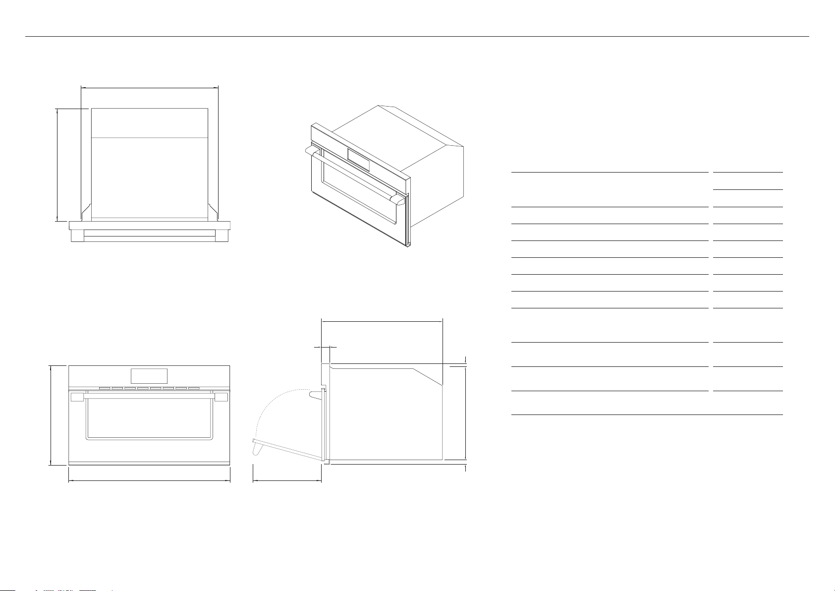
FRONT ELEVATION
without front panels
DETAIL – PLAN VIEW
SIDE ELEVATION
with front panels
A D
B
I
G
J
G
J
H
E
C
F
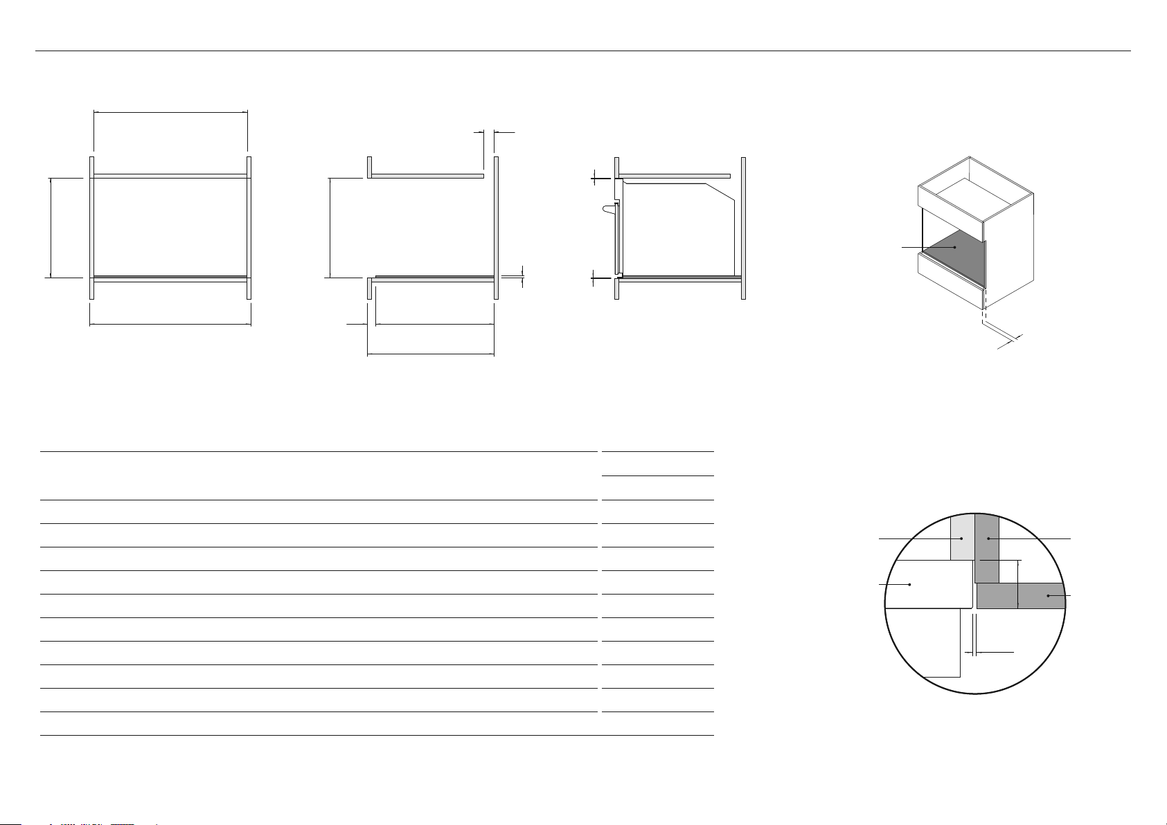
Ventilation of 50x560mm or totalling
280cm
2
is required for companion
products. The air vent must be located
at the rear of cabinet, it can be
positioned at the base, top, sides, or
back of the cavity.
Additional spacer
Sidewall of
appliance cabinet
Sidewall
of adjacent
cabinet
Front panel
of adjacent
cabinet
Steam/Speed Oven
Min
2mm
39mm
Critical rebate to
achieve flush finish
CAVITY DIMENSIONS
OS76 MODELS
MM
A Minimum inside height of cavity 474
B Minimum inside width of cavity 645
C Minimum inside depth of cavity (from front of rebate) 560
D Minimum height between cabinetry front panels 474
E Overall width of cabinetry 762
F Minimum overall depth of cavity (incl. front panel) 600
G Rebate depth for flush install (incl. front panel) 39
H Overall height of spacer in base of cavity 12
I Ventilation gap 50
J Minimum clearance to adjacent cabinetry or other appliances 2
CABINETRY DIMENSIONS (FLUSH INSTALL)
7
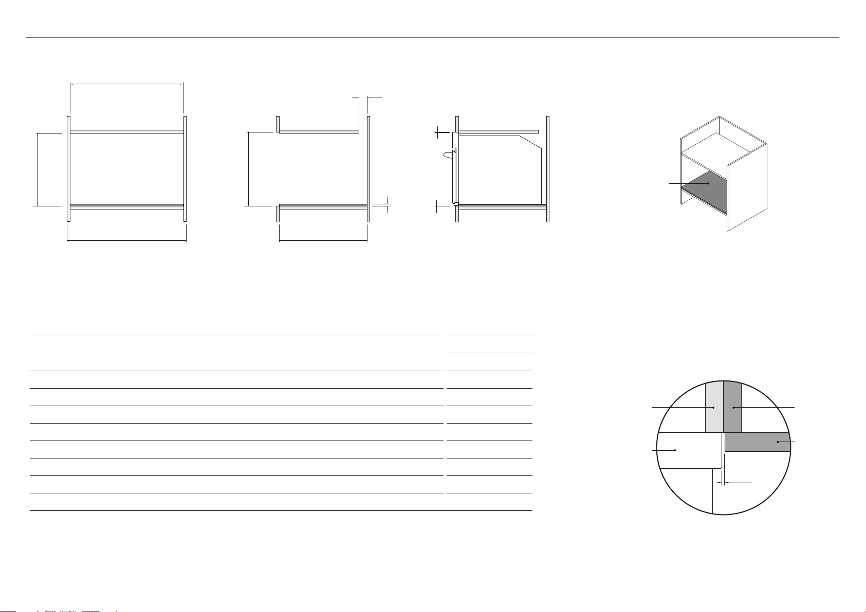
FRONT ELEVATION
without front panels
DETAIL – PLAN VIEW
SIDE ELEVATION
with front panels
A D
B
G
H
H
F
E C
Ventilation of 50x560mm or totalling
280cm
2
is required for companion
products. The air vent must be located
at the rear of cabinet, it can be
positioned at the base, top, sides, or
back of the cavity.
Sidewall of
appliance cabinet
Sidewall
of adjacent
cabinet
Front panel
of adjacent
cabinet
Steam/Speed Oven
Min
2mm
CAVITY DIMENSIONS
OS76 MODELS
MM
A Minimum inside height of cavity 467
B Minimum inside width of cavity 645
C Minimum inside depth of cavity 560
D Minimum height between cabinetry front panels 474
E Overall width of cabinetry 762
F Overall height of spacer in base of cavity 12
G Ventilation gap 50
H Minimum clearance to adjacent cabinetry or other appliances 2
CABINETRY DIMENSIONS (PROUD INSTALL)
Additional spacer
8
z
Do not lift the oven by the door handle.
z
Do not over-tighten the screws.
z
Do not seal the oven into the cabinetry with silicone or glue. This makes future servicing
difficult. Fisher & Paykel will not cover the costs of removing the oven, or of damage
caused by this removal.
z
Take care not to bend the tabs for the lower trim while installing the oven.
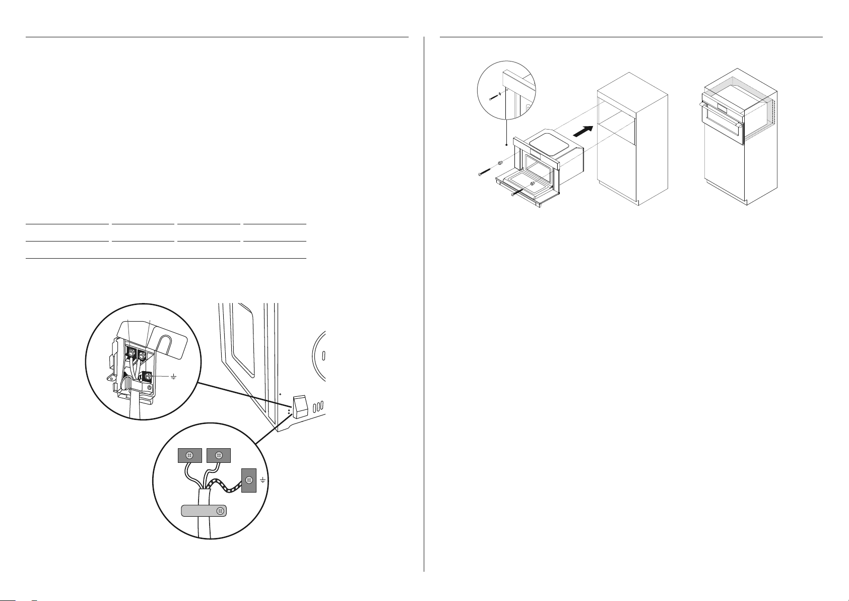
1 Position the oven in the prepared cavity. Make sure the oven is centered and level.
2 Open the oven door fully.
3 Mark and pre-drill the screw holes.
4 Place the supplied washers onto the mounting screws, then use to secure the oven to
the cabinetry.
SECURE THE OVEN TO THE CABINETRYELECTRICAL CONNECTION
Before connecting the oven to the mains power supply, check that:
z
specifications of the electrical system match with what is detailed on this section.
z
system has an effective ground connection compliant with current standards and laws.
The ground connection is required by law. The cable must not, at any point, reach a
temperature greater than 50°C above room temperature.
This oven must be connected to the electricity through a power supply cable and plug
that is compatible with the outlet of the electrical system that powers this oven. If a
fixed appliance does not have a power cord and plug, or another device that ensures
disconnection from the mains, with an opening distance of the contacts that allows complete
disconnection, such disconnection devices must be provided in the power supply mains
conforming to the installation rules.
The omnipolar socket or switch must be easy to reach when the appliance is installed.
Note: The manufacturer declines all liability if the usual accident prevention standards and
the above instructions are not followed.
MAX POWER HZ VOLTAGE (V) AMPS (A)
3200 50 Hz 220 - 240V 14.5
Nl
Nl
cable
clamp
9
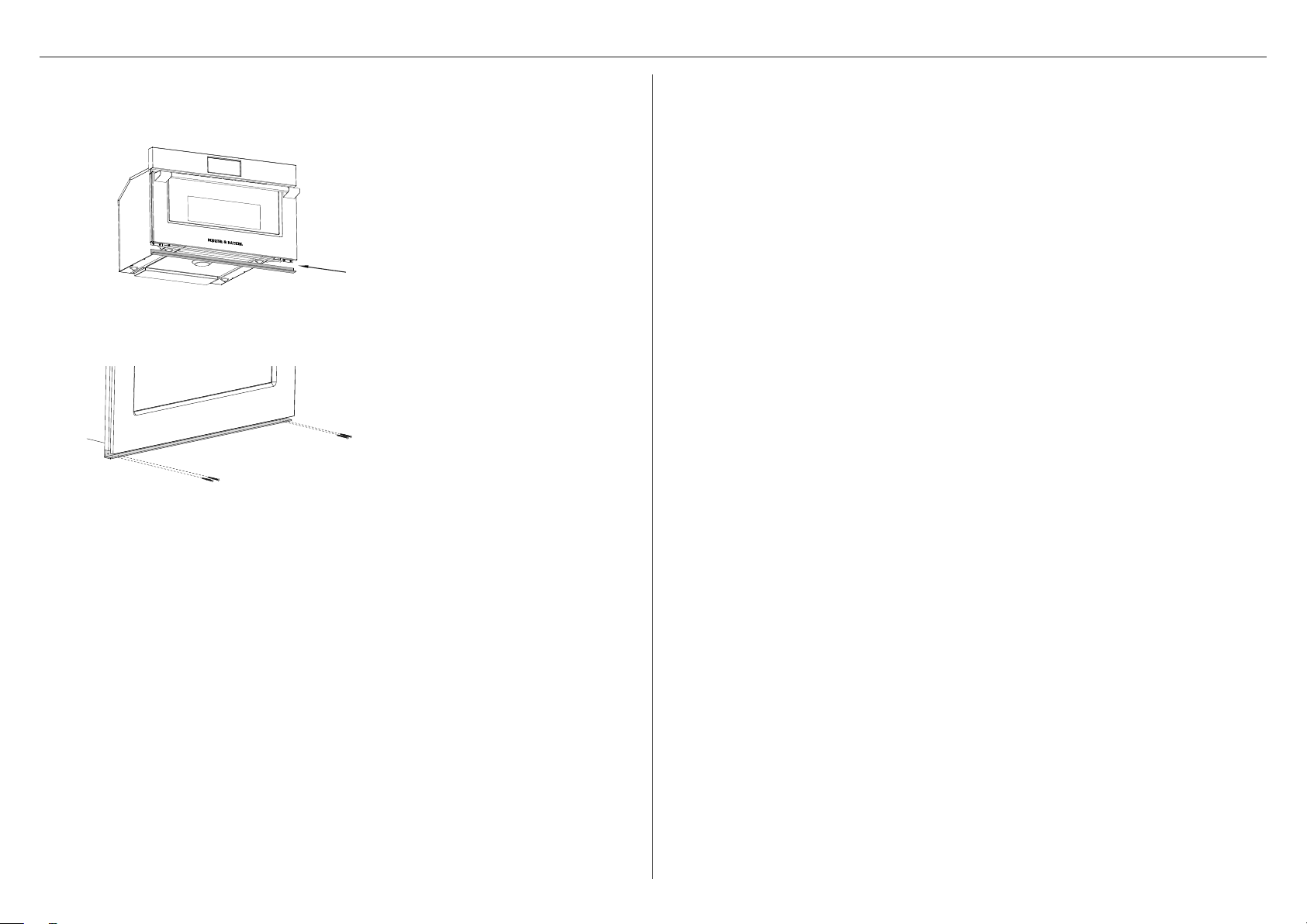
Attach the lower trim to the oven after installing the oven in the cabinetry.
1
Align the lower trim with the tabs on
the base of the oven.
Use the supplied screws to attach
the lower trim to the tabs.
Take care not to bend the tabs
while installing.
Do not over-tighten the screws.
2
ATTACH THE LOWER TRIM TO THE OVEN

10
INSTALLER CHECKLIST
TO BE COMPLETED BY THE INSTALLER
Turn the power to the oven on. The display should turn on..
Have you demonstrated basic operation to the customer?
Make sure the oven is level and securely fitted to the cabinetry.
Check the lower trim is correctly attached and undamaged.
Ensure the oven door opens fully without obstruction.
Open the oven door slowly until it is fully open and check there is adequate clearance
between the bottom of the door and the lower trim. This is to ensure correct air
circulation.
Make sure any cable ties and internal packaging have been removed from the
oven cavity.
Make sure all oven vents and openings are clear and free of any obstruction or damage.
Failure to make sure all oven vents are clear may result in poor product performance.
Make sure the isolating switch is accessible by the customer.
Complete and keep for safe reference:
Model
Serial No.
Purchase Date
Purchaser
Dealer Address
Installer’s Name
Installer’s Signature
Installation Company
Installation Date

59287A 12.21
FISHERPAYKEL.COM
© Fisher & Paykel Appliances 2021. All rights reserved.
The models shown in this guide may not be available in all markets
and are subject to change at any time.
The product specifications in this guide apply to the specific products and
models described at the date of issue. Under our policy of continuous product
improvement, these specifications may change at any time.
For current details about model and specification availability in your country,
please go to our website or contact your local Fisher&Paykel dealer.