HCD1010R/N, HMF1010R/N, HCD1410R/N, HMF1410R/N 1
HCD1010R/N, HCD1410R/N, HMF1010R/N, HMF1410R/N
Horizon Elite™ Ice Machines (Remote Condensing)
801 Church Lane • Easton, PA 18040, USA
Toll free (877) 612-5086 • +1 (610) 252-7301
www.follettice.com
Following installation, please forward this manual
to the appropriate operations person.
Operation and Service Manual
After Serial Number L60417
Order parts online
www.follettice.com
01096122R08

2 HCD1010R/N, HMF1010R/N, HCD1410R/N, HMF1410R/N

HCD1010R/N, HMF1010R/N, HCD1410R/N, HMF1410R/N 3
Contents
Welcome to Follett. . . . . . . . . . . . . . . . . . . . . . . . . . . . . . . . . . . . . . . . . . . . . . . . . . . . . . . . . . . . . . . . . . . . . . . . . . . . . . 4
Before you begin ............................................................................... 4
Specications ................................................................................. 5
Electrical ................................................................................... 5
Evaporator unit ..............................................................................5
Condensing unit .............................................................................5
Evaporator plumbing ..........................................................................5
Ambient .................................................................................... 5
Refrigeration ................................................................................5
Weight ..................................................................................... 5
Ice production ...............................................................................6
Dimensions and clearances ....................................................................7
Operation .....................................................................................9
Cleaning/sanitizing and preventive maintenance (all models) ..........................................9
Service ...................................................................................... 13
Ice machine operation (all models) ............................................................. 13
“Bin full” detection system ..................................................................... 15
Electrical system ............................................................................ 16
Mechanical System ............................................................................21
Evaporator disassembly ......................................................................21
Evaporator reassembly ....................................................................... 24
Refrigeration system ......................................................................... 29
Troubleshooting .............................................................................. 32
Replacement parts ............................................................................ 34
Evaporator assembly ........................................................................34
Low-side assembly ..........................................................................36
Electrical box ..............................................................................38
Integration kit – top-mount and RIDE remote ice delivery ........................................... 40
Skins assembly ............................................................................. 42
1010 Single-phase condensing unit .............................................................44
1410 Single-phase condensing unit ............................................................. 45
1010 3-phase condensing unit ................................................................. 46
1410 3-phase condensing unit ................................................................. 47
4 HCD1010R/N, HMF1010R/N, HCD1410R/N, HMF1410R/N
Welcome to Follett
Follett equipment enjoys a well-deserved reputation for excellent performance, long-term reliability and outstanding
after-the-sale support. To ensure that this equipment delivers the same degree of service, we ask that you review
the installation manual (provided as a separate document) before beginning to install the unit. Our instructions are
designed to help you achieve a trouble-free installation. Should you have any questions or require technical help at
any time, please call our technical service group at (877) 612-5086 or +1 (610) 252-7301.
Before you begin
After uncrating and removing all packing material, inspect the equipment for concealed shipping damage. If
damage is found, notify the shipper immediately and contact Follett LLC so that we can help in the ling of a claim,
if necessary.
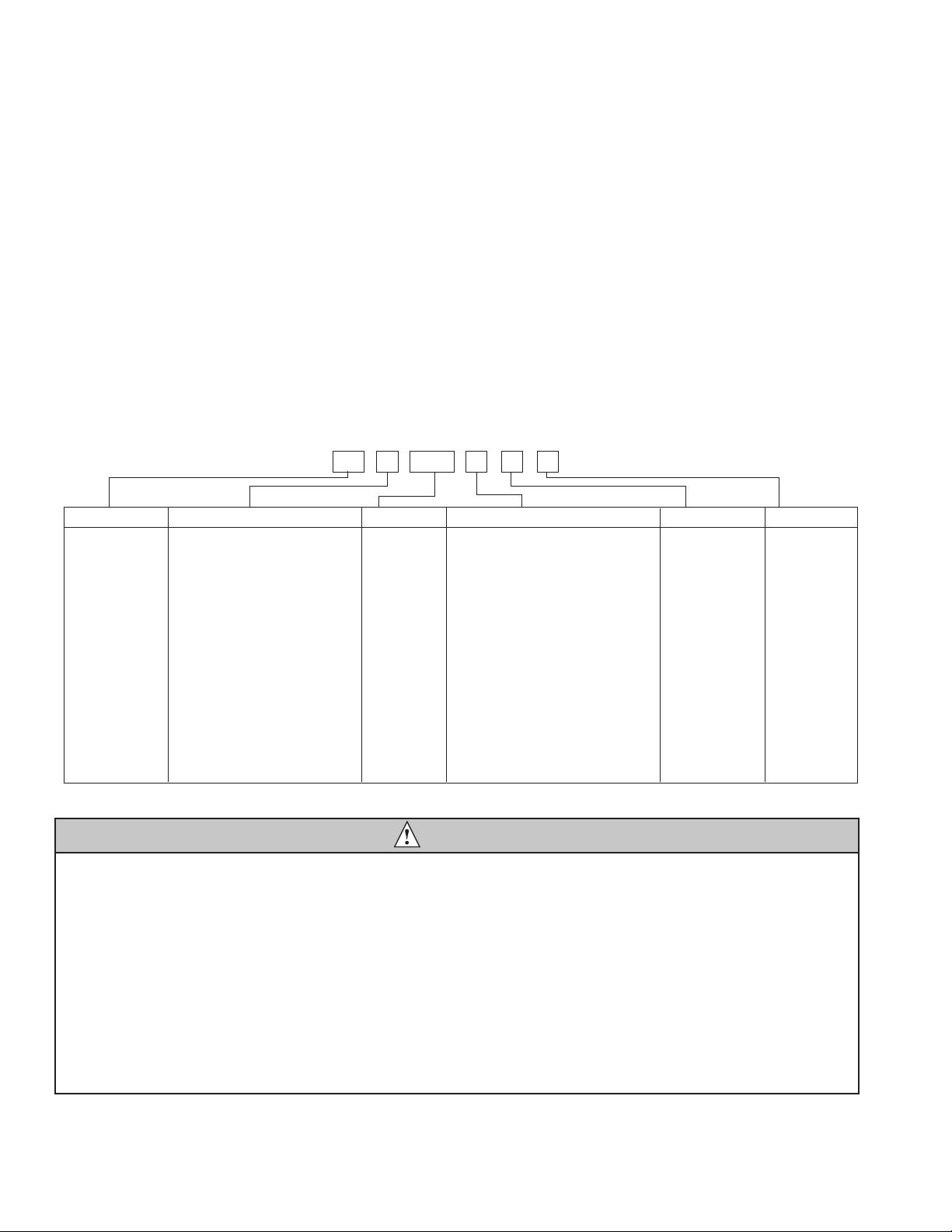
Check your paperwork to determine which model you have. Follett model numbers are designed to provide
information about the type and capacity of Follett equipment. Following is an explanation of the different model
numbers in the series.
ConfigurationApplication
S RIDE™
(RIDE remote
ice delivery
equipment)
T Top-mount
425 up to
425 lbs
(193 kg)
710 up to
675 lbs
(306 kg)
1010 up to
1061 lbs
(482 kg)
1410 up to
1466 lbs
(665 kg)
1810 up to
1790 lbs
(812 kg)
2110 up to
2039 lbs
(925 kg)
V Vision™
H Harmony™
B Ice storage bin
J Drop-in
M Ice Manager
diverter valve
system
P Cornelius Profile
PR150
CondenserSeriesVoltageIcemaker
C 208-230/60/1 (icemaking head)
Self-contained only.
D 115/60/1 (icemaking head)
Self-contained and remote. If remote
unit, high side is 208-230/60/1.
E 230/50/1 (icemaking head)
Self-contained only.
F 115/60/1 (icemaking head)
Remote only. High side is
208-230/60/3.
MC Maestro™
Chewblet
®
(425 Series)
HC Horizon
Chewblet
(710, 1010,
1410, 1810,
2110 Series)
HM Horizon
Micro Chewblet
HC 1810D SVA
A Air-cooled, self-contained
W Water-cooled, self-contained
R Air-cooled, remote condensing unit
N Air-cooled, no condensing unit for
connection to parallel rack system
Chewblet
®
Ice Machine Model Number Configurations
CAUTION
• Warranty does not cover exterior or outside installations.
• Moving parts. Do not operate with front cover removed.
• Hot parts. Do not operate with cover removed.
• To reduce risk of shock, disconnect power before servicing.
• Drain line must not be vented.
• Water supply must have particle ltration.
• Most ice machine cleaners contain citric or phosphoric acid, which can cause skin irritation. Read caution label
on product and follow instructions carefully.
• Ice is slippery. Maintain counters and oors around dispenser in a clean and ice-free condition.
• Ice is food. Follow recommended cleaning instructions to maintain cleanliness of delivered ice.
HCD1010R/N, HMF1010R/N, HCD1410R/N, HMF1410R/N 5
Specications
Electrical
Separate circuit and equipment ground required.
Evaporator unit
Standard electrical: 115/60/1
Maximum fuse: 15A
Amperage: 5A
Condensing unit
1010
Single-Phase
(Tecumseh)
1010
3-Phase
(Tecumseh)
1410
Single-Phase
(Tecumseh)
1410
3-Phase
(Tecumseh)
1410
3-Phase
(Larkin
LZT015M6CFIM)
1410
3-Phase
(Larkin
LCH0015MCACZ)
Electrical 208-230 V,
60 Hz
208-230 V,
60 Hz
208-230 V,
60 Hz
208-230 V,
60 Hz
208-230 V,
60 Hz
208-230 V,
60 Hz
Max Circuit
HVACR breaker
size
15A 15A 30A 25A 15A 20A
Min Circuit
Ampacity
10.7A 9.9A 19.3A 14.2A 15A 15A
Evaporator plumbing
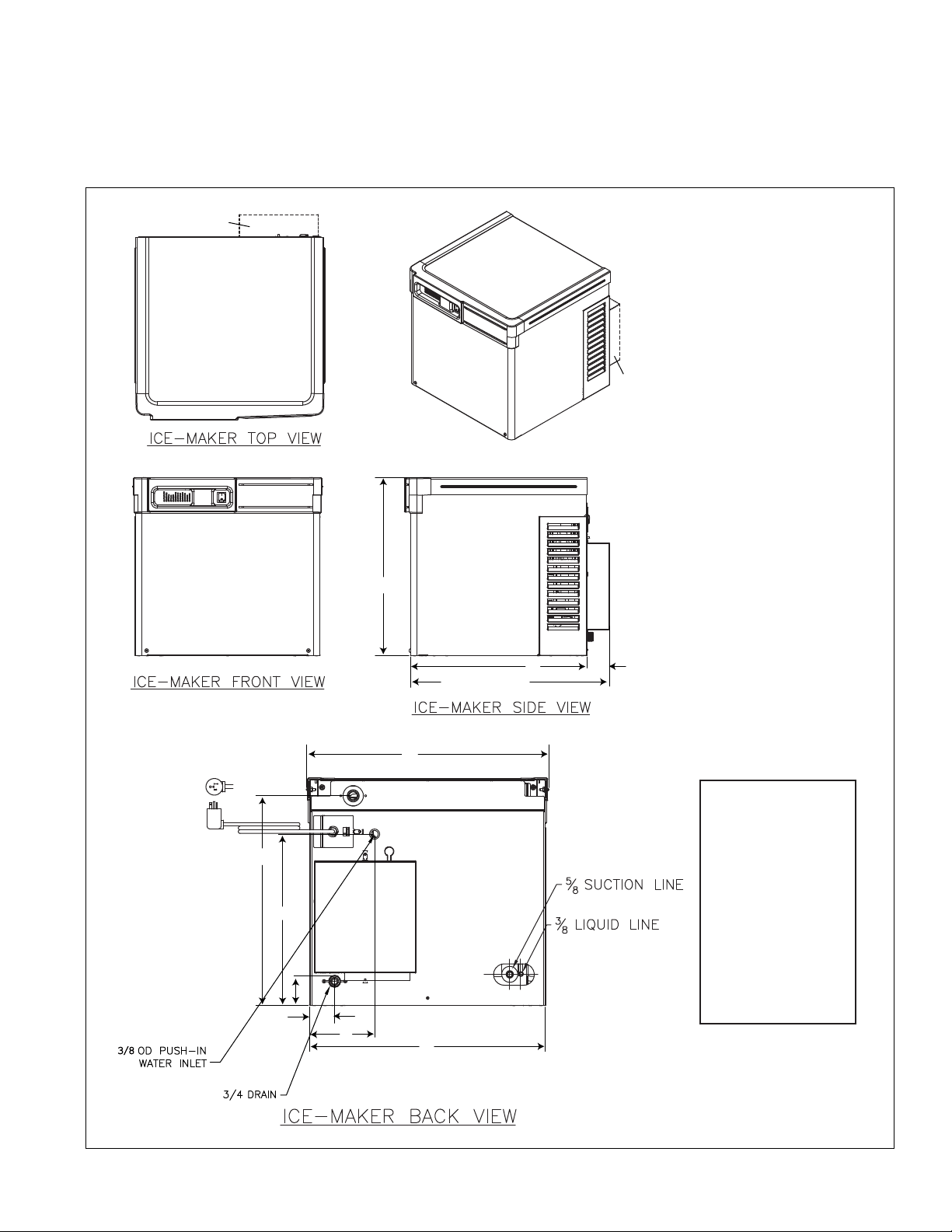
§ 3/8" OD push-in water inlet (connection inside machine) - 3/8" OD tubing required.
§ Water shut-off recommended within 10 feet (3 m).
§ Follett recommends installation of Follett water lter system (part# 00130286) in ice machine inlet water line.
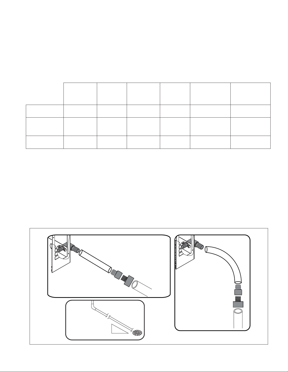
Flush drain plumbing
§ 3/4" MPT ush drain connection at the rear of the machine.
§ Drain must slope 1/4" inch per foot (6 mm per 30.4 cm).
§ Drain line should not be shared with any other piece of equipment.
§ Drain line cannot be reduced to a size smaller than 1 inch.
§ Drain should be piped without a vent.
3/4" barb x 3/4" FPT
1" Stand pipe/Drain
2 ft. x 1" OD
silicone tubing
Minimum 8"
radius
3/4" MPT x 1" slip
1" PVC Drain
2 ft. x 1" OD
silicone tubing
3/4" MPT x 1" slip
3/4" barb x 3/4" FPT
1'
1/4" per foot
(6,4 mm per 0,3 m)
6 HCD1010R/N, HMF1010R/N, HCD1410R/N, HMF1410R/N
Ambient
Evaporator unit
Air temperature: 100 F/38 C max. 50 F/10 C min.
Water temperature: 90 F/32 C max. 45 F/7 C min.
Water pressure: 70 psi max. (483 kPa) 10 psi min. (69 kPa)
Condenser unit
Air temperature: 120 F/49 C max. –20F/–29C min.
Refrigeration
§ 3/8" liquid line
§ 5/8" suction line
Note: Rack system installations require a capacity of 10,000 BTU/hr for 1010 machines and 13,000 BTU/hr for
1410 machines at 0 F (–18 C) evaporator temperature. Evaporator pressure regulator (not supplied) is
required.
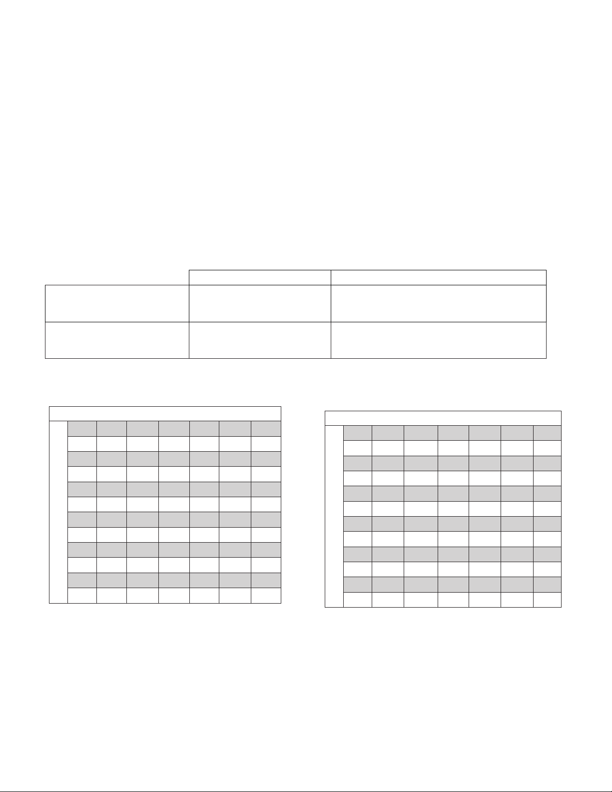
Weight
Evaporator unit: 125 lbs (57 kg)
Condensing unit:
Horizon Elite 1010 series Horizon Elite 1410 series
Approximate ship weight 260 lb (118 kg) 270 lb (122 kg) – single phase (Tecumseh)
270 lb (122 kg) – three phase (Tecumseh)
230 lb (104 kg) – three phase
(Larkin)
Approximate net weight 250 lb (114 kg) 260 lb (118 kg) – single phase (Tecumseh)
260 lb (118 kg) – three phase (Tecumseh)
210 lb (95 kg) – three phase (Larkin)
Ice production
1010 ice machine capacity/24 hrs.
Ambient Air Temperature F/C
Evap Potable Water Temperature F/C
F 60 70 80 90 100
C 16 21 27 32 38
50 1051 978 906 834 763 lbs
10 477 444 411 379 346 kg
60 994 925 855 796 737 lbs
16 451 420 388 361 335 kg
70 937 871 805 758 7 11 lbs
21 425 395 365 344 323 kg
80 904 839 774 727 680 lbs
27 410 381 351 330 309 kg
90 872 807 743 696 648 lbs
32 396 366 337 316 294 kg
1410 ice machine capacity/24 hrs.
Ambient Air Temperature F/C
Evap Potable Water Temperature F/C
F 60 70 80 90 100
C 16 21 27 32 38
50 1474 1372 1269 1212 115 4 lbs
10 669 623 576 550 524 kg
60 1385 1292 119 8 114 8 1097 lbs
16 628 586 544 521 498 kg
70 1296 1212 1127 1083 1039 lbs
21 588 550 5 11 492 472 kg
80 1239 115 5 1072 1030 988 lbs
27 562 524 487 468 449 kg
90 90 118 1 1099 1017 976 lbs
32 32 536 499 462 425 kg
HCD1010R/N, HMF1010R/N, HCD1410R/N, HMF1410R/N 7
Dimensions and clearances
§ Entire front of ice machine must be clear of obstructions/connections to allow removal.
§ 1" (26mm) clearance above ice machine for service.
§ 1" (26mm) minimum clearance on sides.
§ The intake and exhaust air grilles must provide at least 250 sq in (1615 sq cm) of open area.
§ Air-cooled ice machines – 18" (458 mm) minimum clearance between discharge and air intake-grilles.
A 21.26" (54.0 cm)
B 21.11" (53.6 cm)
C 23.77" (60.4 cm)
D 2.66" (6.8 cm)
E 19.59" (49.8 cm)
F 16.00" (40.6 cm)
G 2.73" (6.9 cm)
H 2.28" (15.3 cm)
I 6.04" (5.8 cm)
J 22.00" (55.9 cm)
K 22.69" (57.6 cm)
A
B
C (1410 ONLY)
D (1410 ONLY)
NEMA 5-15
RIGHT ANGLE
E
F
H
J
I
G
K
1410 ONLY
1410 ONLY
8 HCD1010R/N, HMF1010R/N, HCD1410R/N, HMF1410R/N
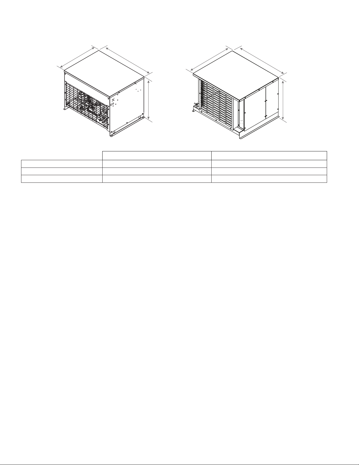
Condensing Unit
W1
D1
H1
W1
D1
H1
1010/1410 single phase (Tecumseh)
1010 three phase (Tecumseh)
1410 three phase (Larkin)
Horizon Elite 1010/1410 (Tecumseh) Horizon Elite 1410 three phase (Larkin)
W1 Width 36.25" (91.4 cm) – all models 37.75" (95.9 cm) – three phase (Larkin)
D1 Depth 25.50" (64.8 cm) – all models 28.25" (71.6 cm) – three phase (Larkin)
H1 Height 26.10" (66.3 cm) – all models 19.75" (50.2 cm) – three phase (Larkin)
HCD1010R/N, HMF1010R/N, HCD1410R/N, HMF1410R/N 9
Operation
Cleaning/sanitizing and preventive maintenance (all models)
Note: Do not use bleach to sanitize or clean the icemaker.
Preventive maintenance
Periodic cleaning of Follett’s icemaker system is required to ensure peak performance and delivery of clean,
sanitary ice. The recommended cleaning procedures that follow should be performed at least as frequently as
recommended, and more often if environmental conditions dictate.
Cleaning of the condenser can usually be performed by facility personnel. Cleaning of the icemaker system,
in most cases, should be performed by your facility’s maintenance staff or a Follett authorized service agent.
Regardless of who performs the cleaning, it is the operator’s responsibility to see that this cleaning is performed
according to the schedule below. Service problems resulting from lack of preventive maintenance will not be
covered under the Follett warranty.
Weekly exterior care
The exterior may be cleaned with a stainless cleaner such as 3M Stainless Steel Cleaner & Polish or equivalent.
Monthly condenser cleaning (air-cooled icemaker only)
1. Use a vacuum cleaner or stiff brush to carefully clean condenser coils of air-cooled icemakers to ensure
optimal performance.
2. When reinstalling counter panels in front of remote icemakers, be sure that ventilation louvers line up with
condenser air duct.
Semi-annual evaporator cleaning (every 6 months)
WARNING
• Wear rubber gloves and safety goggles (and/or face shield) when handling ice machine cleaner or sanitizer.
CAUTION
• Use only Follett approved SafeCLEAN Plus™ cleaning solution.
• DO NOT USE BLEACH.
• It is a violation of Federal law to use these solutions in a manner inconsistent with their labeling.
• Read and understand all labels printed on packaging before use.
Note: Complete procedure for cleaning an sanitizing MUST be followed. Ice must be collected for 10minutes
before putting ice machine back into service.
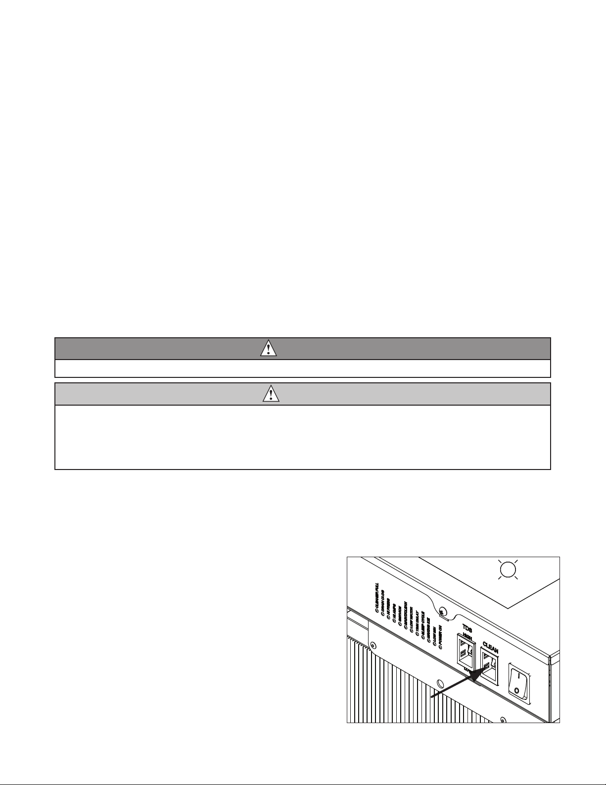
Fig. 1
1. Press the CLEAN button. The machine will drain. The
auger will run for a short time and then stop. Wait for
the LOW WATER light to come on.
LO WATER
10 HCD1010R/N, HMF1010R/N, HCD1410R/N, HMF1410R/N
Fig. 2
2. Follow the directions on the SafeCLEAN Plus
packaging to mix 1 gal. (3.8 L) of Follett SafeCLEAN
Plus solution. Use 100 F (38 C) water.
3. Using a 1 quart (1L) container, slowly ll cleaning cup
until CLEANER FULL light comes on. Do not overll.
4. Place one Sani-Sponge™ in remaining sanitizing and
cleaning solution and retain for Step 9.
Note: Do not use bleach to sanitize or clean the icemaker.
CLEANER FULL
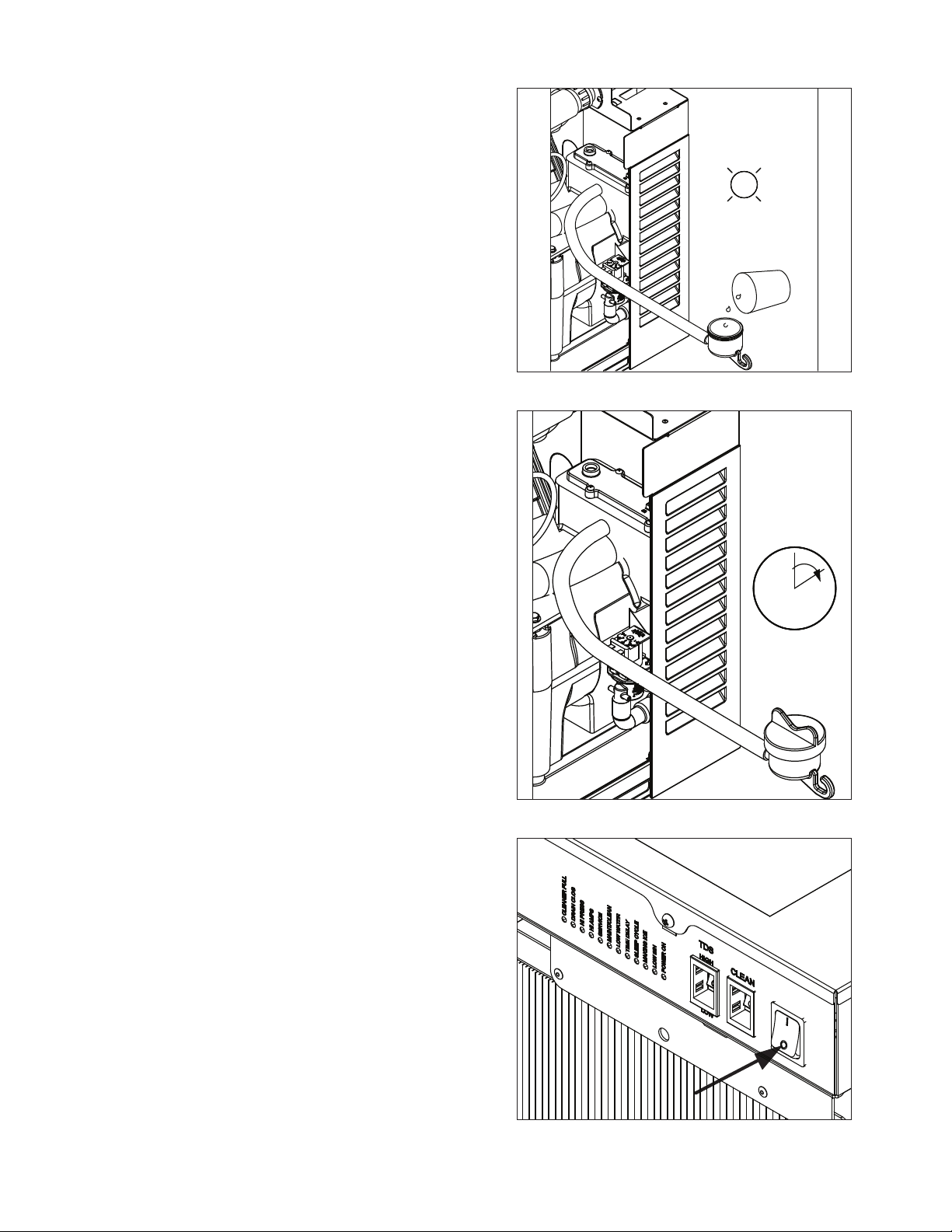
Fig. 3
5. Replace cover on cleaner cup. Machine will clean,
then ush 3 times in approximately 15 minutes. Wait
until machine restarts.
15
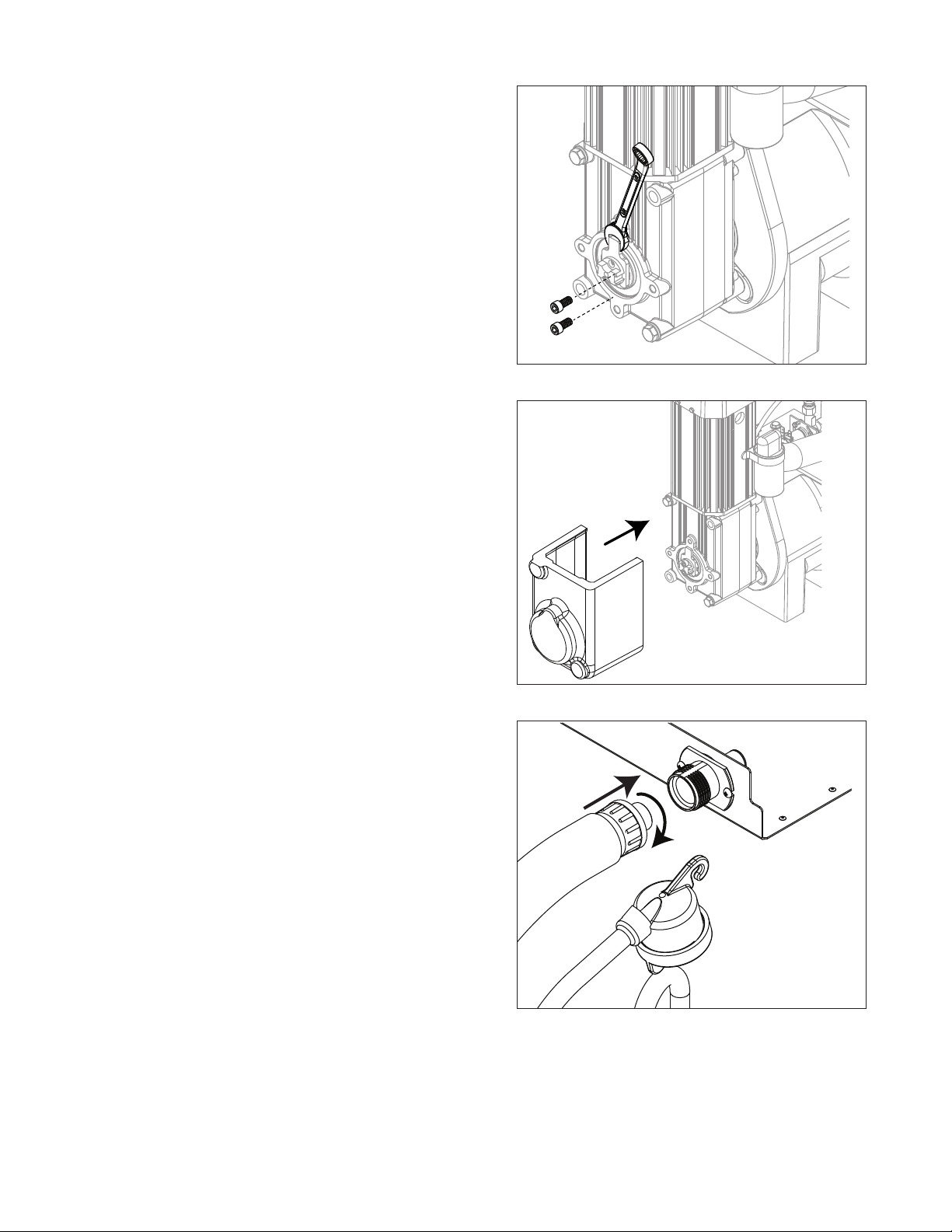
Fig. 4
6. To clean/sanitize ice transport tube – Press power
switch OFF

HCD1010R/N, HMF1010R/N, HCD1410R/N, HMF1410R/N 11
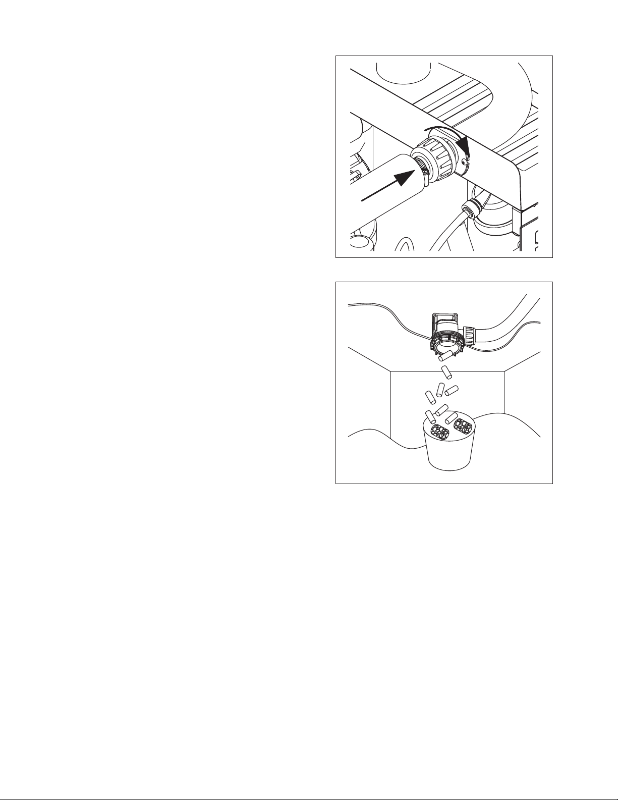
Fig. 5
7. Disconnect coupling as shown.
Fig. 6
8. Using disposable food service grade gloves, insert
dry Sani-Sponge.
9. Insert Sani-Sponge soaked in SafeClean Plus (from
Step 4).
10. Push both Sani-Sponges down ice transport tube
with supplied pusher tube.
1
2
3
16"
(407 mm)
Fig. 7
11. Remove and discard 16 inch (407 mm) pusher tube.
12 HCD1010R/N, HMF1010R/N, HCD1410R/N, HMF1410R/N
Fig. 8
12. Reconnect coupling. Press power switch ON. Ice
pushes Sani-Sponges through ice transport tube.
Fig. 9
13. Place a sanitary (2 gal. or larger) container in bin
or dispenser to collect Sani-Sponges and ice for 10
minutes.
14. Collect 5.5 lbs (3 kg) of ice from unit. Discard ice and
Sani-Sponges.
HCD1010R/N, HMF1010R/N, HCD1410R/N, HMF1410R/N 13
Service
Ice machine operation (all models)
Follett’s ice machine consists of ve distinct functional systems covered in detail as follows:
§ Water system
§ Electrical control system
§ Mechanical assembly
§ Refrigeration system
§ Bin full
The Horizon ice machine overview
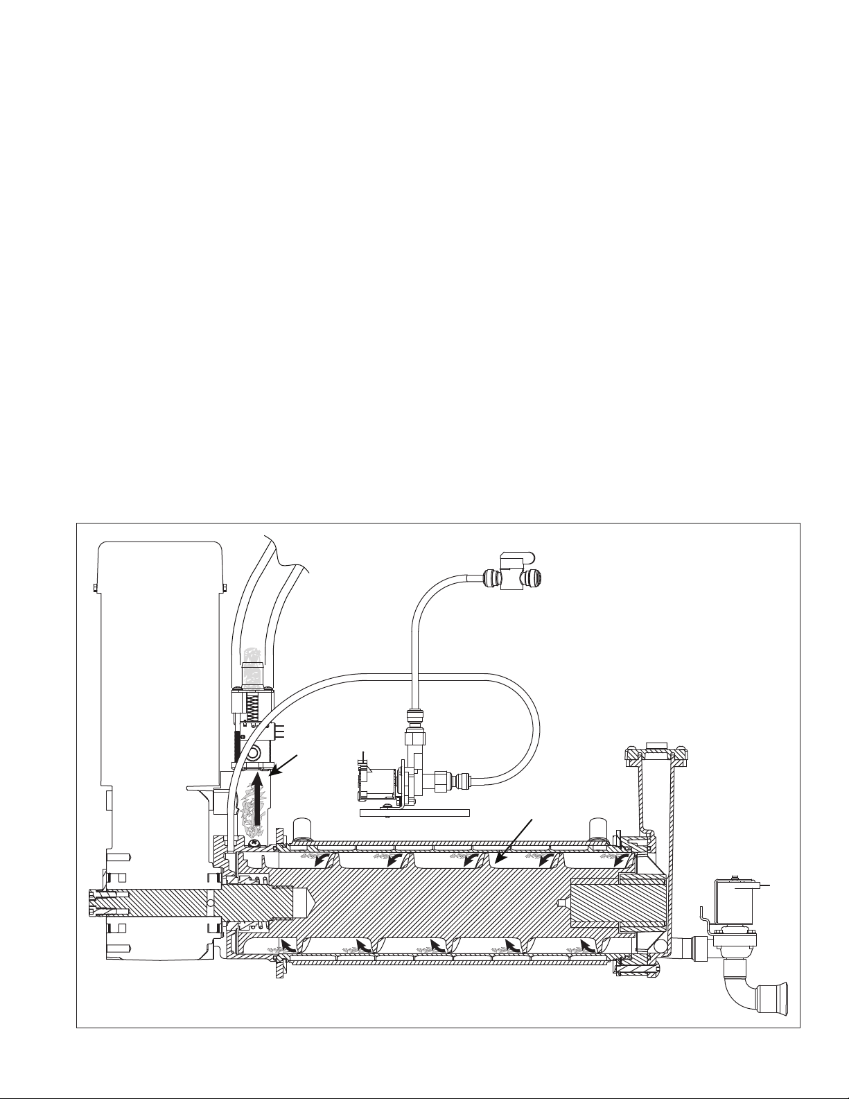
The Follett Horizon ice machine uses a horizontal, cylindrical evaporator to freeze water on its inner surface. The
refrigeration cycle is continuous; there is no batch cycle. The evaporator is ooded with water and the level is
controlled by sensors in a reservoir. A rotating auger (17 RPM) continuously scrapes ice from the inner wall of the
evaporator. The auger moves harvested ice through the evaporator into an ice extrusion canal. The ice is forced
through a restrictive nozzle that squeezes out the water and creates the Chewblet. The continuous extrusion
process pushes the Chewblets through a transport tube into a dispenser or bin.
A solid state PC board controls and monitors the functionality of the ice machine. In addition to sequencing
electrical components, the board monitors various operational parameters. A full complement of indicator lights
allows visual status of the machine's operation. Additionally, the PC board controls the self-ushing feature of the
ice machine. The evaporator water is periodically drained and replenished to remove minerals and sediment.
A unique “bin full” detection system is incorporated in the Horizon ice machine. A switch located at the ice
discharge port of the machine detects the position of the transport tube. When the bin lls up with ice, the transport
tube moves out of the normal running position, and the switch turns the ice maker off. A domed housing at the end
of the transport tube contains the ice extrusion loads during shut down.
Harvest system diagram
Ice Transport Tube
Auger
Compression
Nozzle
Water Inlet
14 HCD1010R/N, HMF1010R/N, HCD1410R/N, HMF1410R/N
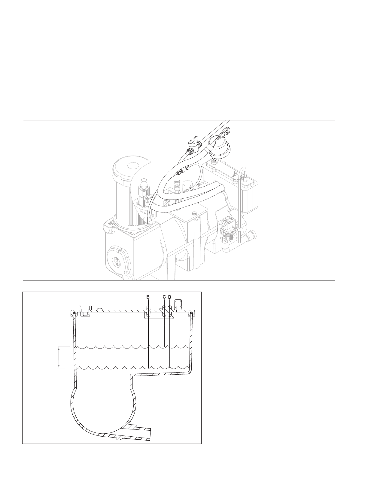
Water system
The water level in the evaporator is controlled by a feed solenoid and level detecting sensors. Referencing the
diagram below, water sensing probes extend down into the reservoir at the end of the evaporator assembly. The
system works via electrical conductivity as follows:
The probe labeled B is the common. When water is between any of the other probes and the common, the PC
board will sense the activation. During normal operation, the water level rises and falls between the Normal
High and Normal Low probes. As water is consumed to make ice, the level will fall until the Normal Low probe is
exposed, triggering the water feed solenoid on. Water will ll until the Normal High sensor is activated.
Note: The potable water total dissolved solids (TDS) content must be greater than 10 ppm for the water control
system to function properly. If using reverse osmosis water ltration system, ensure TDS level is greater than
10 ppm.
Water system diagram
Water level diagram
Common
Normal Hi
Normal Lo
Normal
Operating
Range

HCD1010R/N, HMF1010R/N, HCD1410R/N, HMF1410R/N 15
“Bin full” detection system
The Follett Horizon ice machine incorporates a unique “bin full” detection system that consists of the shuttle and
actuator. The shuttle incorporates a ag and switch. Referencing the gure below, the normal running position
of the ag is down, and the switch is closed. When the bin lls to the top and ice can no longer move through
the tube, the machine will force the shuttle ag up, opening the switch and shutting the machine off. The shuttle
actuator, located above the ice bin allows the ice to curl up within it when the bin is full. In this way, there are no
loads generated that would tend to lift off the lid of the bin.
Running Off
Running
Off
Shuttle ag and sensor
Shuttle actuator
16 HCD1010R/N, HMF1010R/N, HCD1410R/N, HMF1410R/N
Electrical system
ATTENTION!
To prevent circuit breaker/Hi-amp overload, wait 5 minutes before
restarting this unit. This allows the compressor to equalize and the
evaporator to thaw.
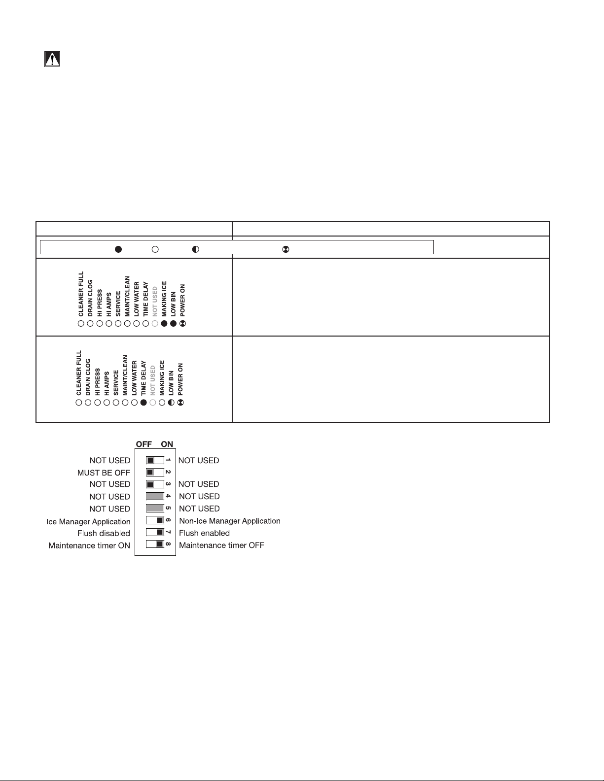
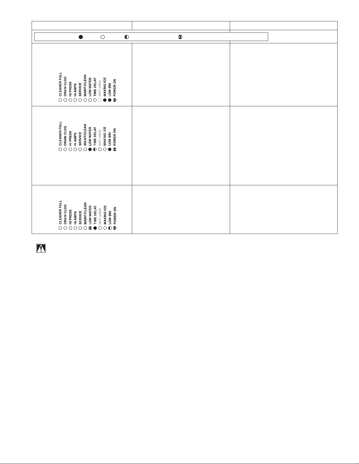
Normal control board operation
The PC board indicator lights provide all the information necessary to determine the machine's status. Green
indicator lights generally represent “go” or normal operation; Yellow indicators represent normal off conditions; Red
indicators generally represent alarm conditions, some of which will lock the machine off.
A ashing green light labeled POWER indicates power to the machine. All other normal operation status indicators
are covered as follows:
Ice machine disposition Operating conditions
FLASHINGON or OFF
Legend:
OFFON
1. Ice machine is making ice.
.
1. Normal running.
2. Ice machine is not making ice.
2. Normal time delay. When the bin lls with ice, the LOW BIN
light goes out momentarily and the refrigeration and auger
drive systems immediately shut down. (Note: The fan motor
will continue to run for 10 minutes to cool condenser) The TIME
DELAY light comes on, initiating the time delay period. When the
time delay expires, the machine will restart provided that the LOW
BIN light is on.
DIP Switch Settings

HCD1010R/N, HMF1010R/N, HCD1410R/N, HMF1410R/N 17
Error faults:
The Horizon PC board monitors various operating parameters including high pressure, auger gearmotor amperage
limits, clogged drain, and low water alarm conditions. There are three types of errors namely “soft” (time delay)
"hard" (reset), and “run”.
§ Soft errors will automatically reset after the 1 hour time delay or can be reset by cycling power.
§ Hard errors must be reset on the control board.
§ Run errors will give an indication of a problem, but will allow continuous normal operation.
Soft errors:
HI AMPS: The PC board monitors the amperage of the auger motor. Should the gear motor experience current
draw above the allowable limit, the machine will shut down and the TIME DELAY and HI AMP will be illuminated.
After the time delay the machine will restart and the TIME DELAY and HI AMP will clear.
LO WATER: During operation, the water level cycles between the normal low and normal high sensors. Should the
water be shut off to a running machine, a soft error will occur. The error sequence is as follows: During operation,
the water level falls to the normal low sensor, and when it does the water feed solenoid is energized. If water is not
detected at the normal low sensor within 10 seconds, a soft error will occur. The machine will shut down, but the
water feed solenoid will remain energized. Should water return, it will ll to the normal low sensor and the machine
will resume normal operation. The error will clear automatically.
HI PRESSURE: Should the refrigeration pressure rise above 425 psi, the machine will shut down and the TIME
DELAY and HIGH PRESSURE will be illuminated. After the time delay, and if the pressure has fallen back below
the reset point of 295 psi, the machine will restart and the TIME DELAY and HIGH PRESSURE will clear.
SERVICE: The water leak sensors, located in the chassis will detect the presence of water just below the top edge
of the chassis.
Hard error:
HI AMPS will light as a hard error if the gearmotor circuit is open (zero current draw). Press reset on the control
board to clear this error.
Run errors:
DRAIN CLOG: When the machine shuts down on a full bin and there has been 10 minutes of cumulative
compressor run time, the machine will purge before starting. During this purge, if water does not get below the low
probe in the reservoir within 20 seconds, the Drain Clog LED will light. The machine will continue to run but this is
an indication of a poorly draining machine and must be addressed.
Relay output indication:
Each relay on the board has an indicator light associated with its output. For example, when the relay for the water
feed solenoid is energized, the adjacent indicator light glows green.
Evaporator ushing sequence:
During operation, the purge solenoid will open in order to drain water. There are two drain settings to choose from:
High TDS or Low TDS. (There is a rocker switch behind the front cover of the machine.) The intent is to drain the
Total Dissolved Solids from the machine while it makes ice.
While ice is being made, the TDS of the water in the evaporator increases in TDS concentration. Without periodic
draining, the TDS levels will climb to very detrimental levels, levels that will cause scale to form and cause poor
machine operation. The Low TDS setting will allow the machine to operate for one hour before going through the
ushing sequence; the High TDS setting will allow the machine to run for 10 minutes before going through the
ushing sequence.
The ushing sequence toggles the purge and ll solenoids three times. That is, the purge solenoid will energize
until the water level drops below the low probe. The ll solenoid then energizes until water reaches the high probe,
and so on for 3 cycles.
Typically, High TDS might be considered levels above 200 PPM, but local experience and varying water chemistry
may compel a High TDS setting for best performance in even lower TDS levels.
Off cycle: During the off-cycle time delay, the machine checks for a cumulative 10 minutes of ice making time
since the last off-cycle ush. If the cumulative ice making time exceeds 10 minutes, the machine will open the
drain valve for 60 seconds to drain the evaporator in its entirety. It will then rell with water and begin making ice.
If the ice making time is less than 10 minutes, the machine will start and begin making ice without draining the
evaporator.
18 HCD1010R/N, HMF1010R/N, HCD1410R/N, HMF1410R/N
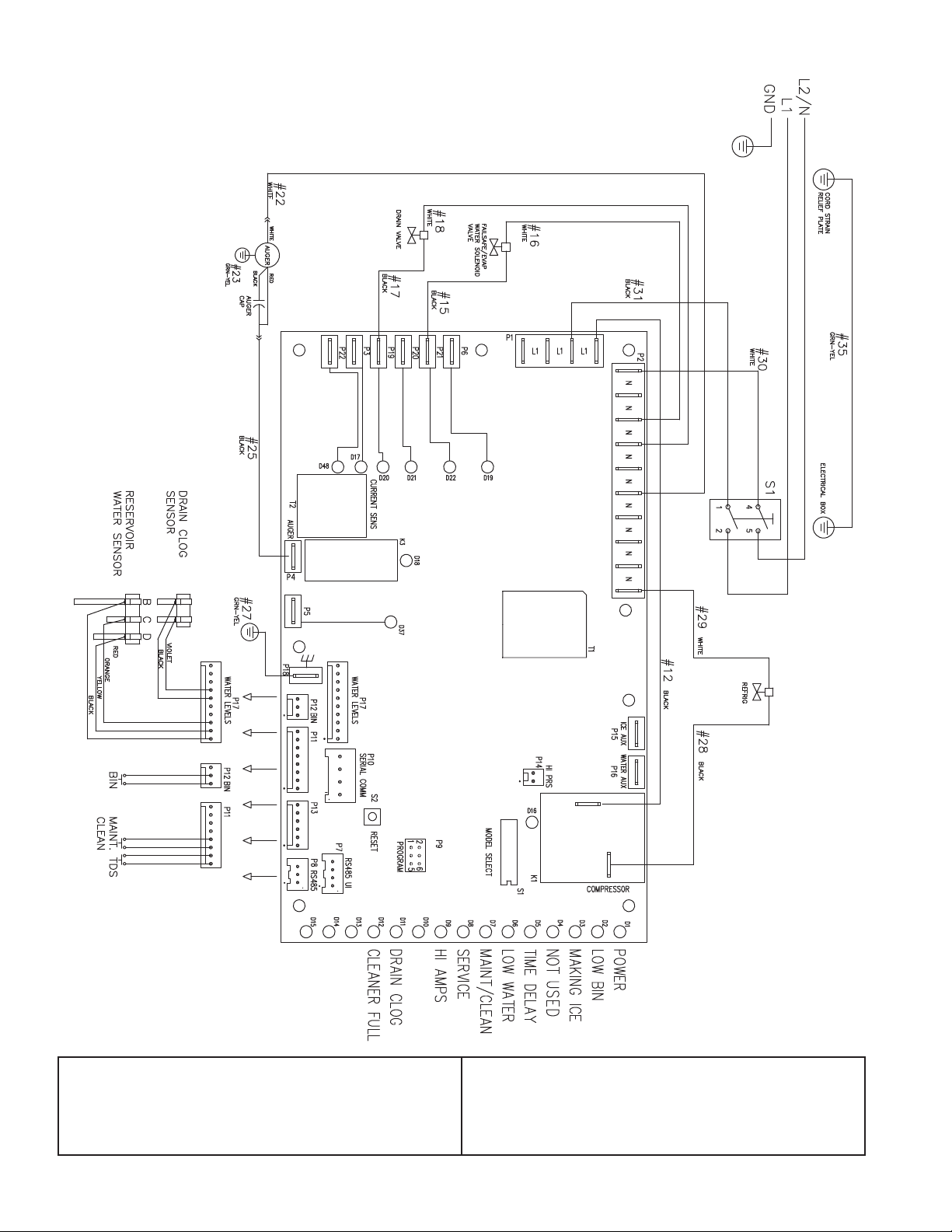
Wiring diagram, evaporator unit
Gearmotor data
Gearmotor current 2.8A @ 115 V
Gearmotor torque-out (high amp) trip point: 5.6A
Resistance of windings
115 vac gearmotor (Bison):
White to Black: 3Ω
White to Red: –3Ω
Red to Black: 6Ω
HCD1010R/N, HMF1010R/N, HCD1410R/N, HMF1410R/N 19
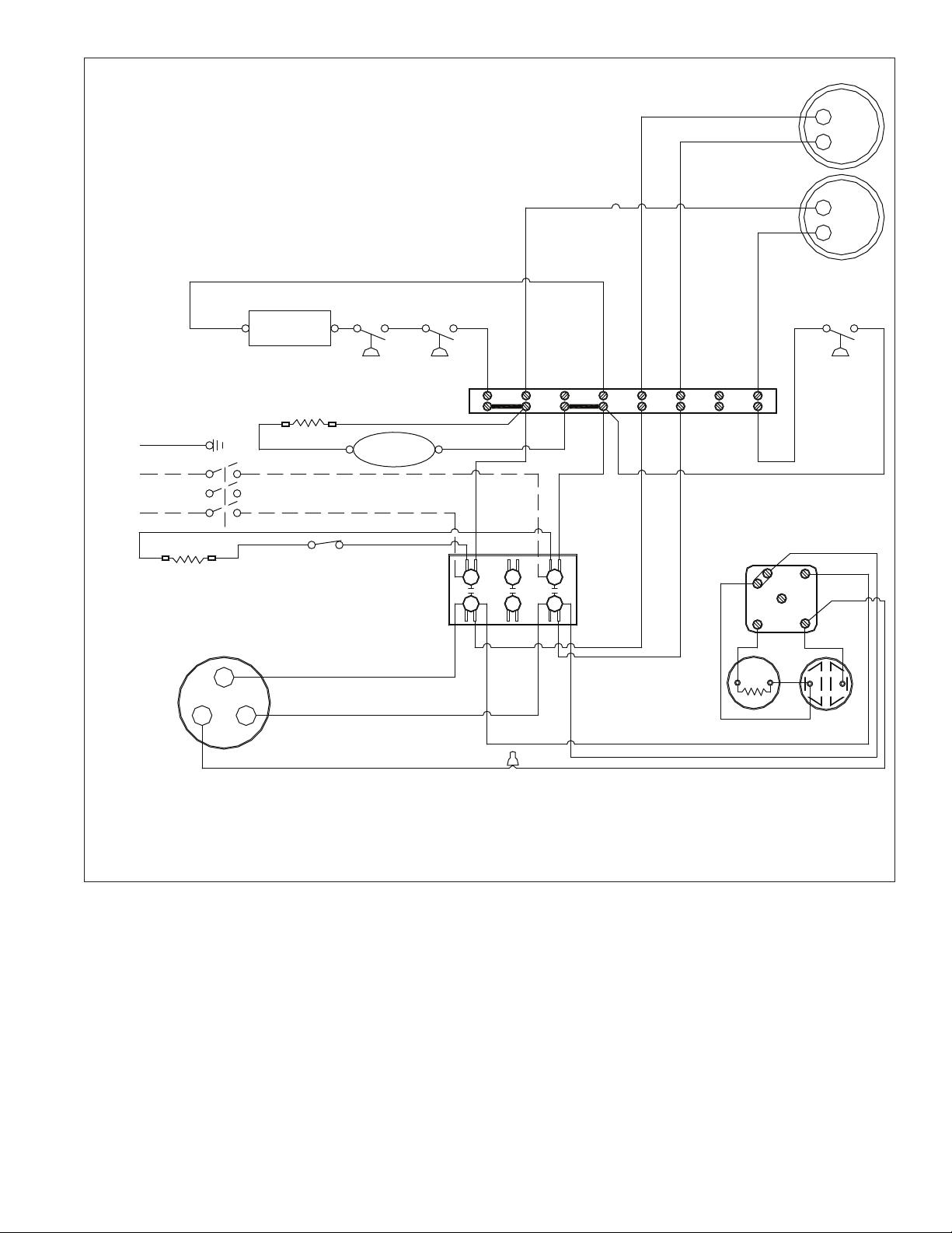
Single-phase condensing unit wiring diagram (Tecumseh)
T1
BLACK
COMPRESSOR
CONTACTOR
T1
L1
T2
L2
RECEIVER
HEATER
L3
L2
T3
T2
COMPRESSOR
CONTACTOR COIL
see note A
TERMINAL
BOARD
P1
HP LP
T3
L3
START
CAPACITOR
WITH BLEEDER
RESISTOR
4
6
1
L2
L3 T3
T1
F1 F2
FC
FAN 1
POTENTIAL RELAY
see note B
5
2
FAN 2
L1
CRANK CASE
HEATER
COMPRESSOR
TERMINAL
C
GRD
L1
S
R
RED
YELLOW
RED
BLACK
YELLOW
RUN
CAPACITOR
HEATER
THERMOSTAT
POWER SUPPLY
230-60-1
COMPRESSOR CONTACTOR
NC AUXILIARY SWITCH
20 HCD1010R/N, HMF1010R/N, HCD1410R/N, HMF1410R/N
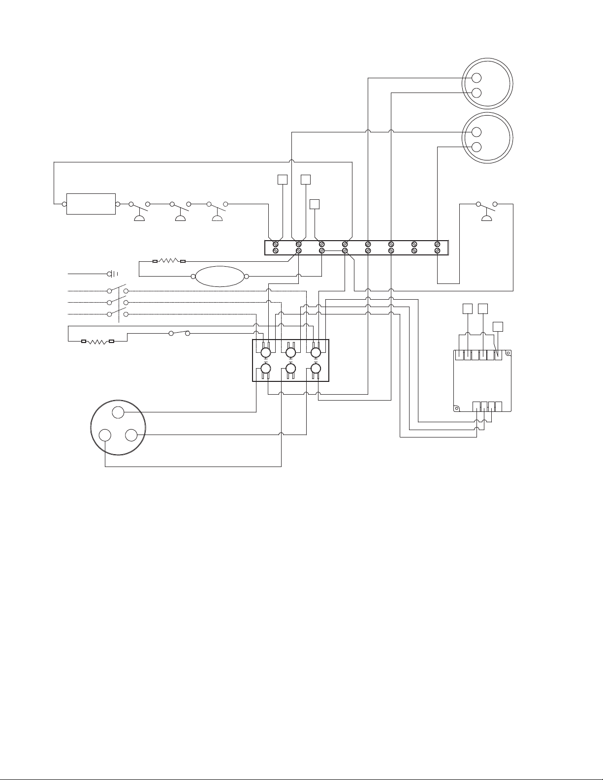
3-phase condensing unit wiring diagram (Tecumseh)
FAN 2
L1
COMPRESSOR
TERMINAL
C
S
R
L1 T1
RED
YELLOW
BLACK
ICM402
3 PHASE
MONITOR
T1
L1
T2
L2
L3
L2
T3
T2
COMPRESSOR
CONTACTOR
COIL
see note A
TERMINAL
BOARD
P1
HP LP
T3
L3
L2 L3 T3T1 F1 F2
FFC
FAN 1
Y-
OUT
C
115
VAC
CRANK CASE
HEATER
230
VAC
L1
D.T.
L2 L3
TO "230 VAC"
AT PHASE
MONITOR
TERMINAL
BOARD
A
B
RECEIVER
HEATER
TO "L1"
AT TERMINAL
BOARD
TO "Y-OUT"
AT PHASE
MONITOR
A
C
TO "C"
AT PHASE
MONITOR
TO "P1"
AT TERMINAL
BOARD
HEATER
THERMOSTAT
COMPRESSOR
CONTACTOR NC
AUXILIARY SWITCH
B
C
GRD
TO "L2"
AT TERMI
NAL
BOARD
POWER SUPPLY
230-60-3
Y
HCD1010R/N, HMF1010R/N, HCD1410R/N, HMF1410R/N 21
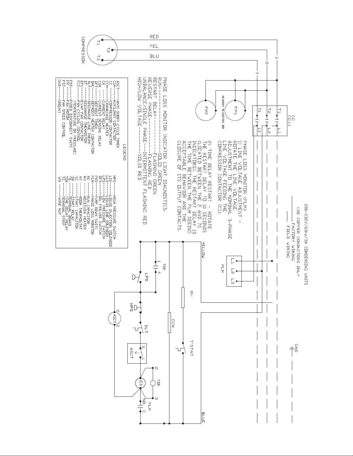
3-phase condensing unit wiring diagram (Larkin)
22 HCD1010R/N, HMF1010R/N, HCD1410R/N, HMF1410R/N
Mechanical System
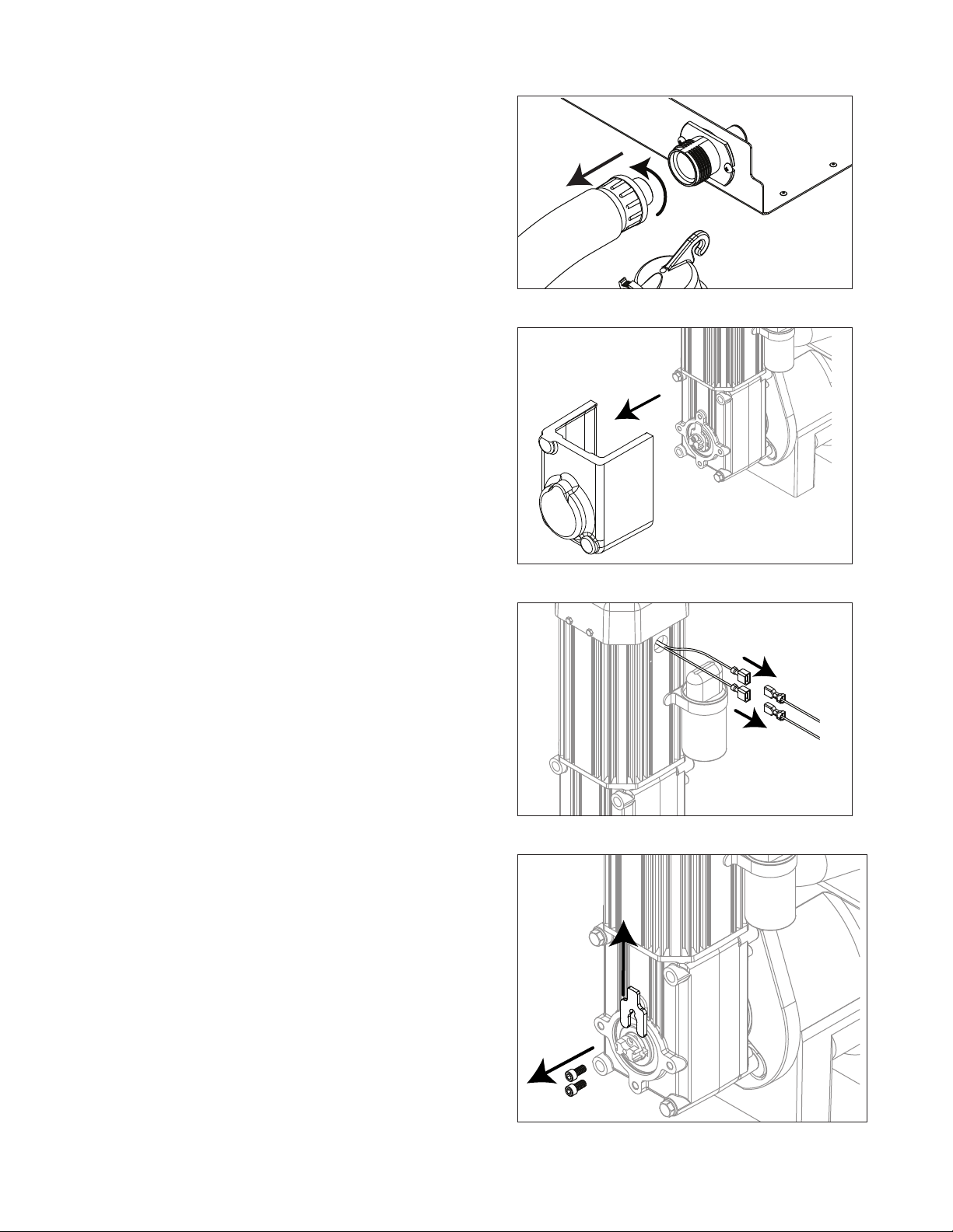
Fig. 10
Evaporator disassembly
1. Press CLEAN button to purge evaporator. Turn power
OFF when LO WATER lights.
2. Unscrew and disconnect transport tube from louvered
docking assembly.
Fig. 11
3. Remove gearbox insulation..
Fig. 12
4. Disconnect gear motor wires.
Fig. 13
5. Remove screws (with 3/16" allen wrench) and auger
retaining fork:

HCD1010R/N, HMF1010R/N, HCD1410R/N, HMF1410R/N 23
Fig. 14
6. Remove gear motor bolts (1/2" wrench).
7. Remove gear motor and wipe auger shaft clean.
WIPE
AUGER
SHAFT
Fig. 15
8. Remove main housing insulation and shuttle
insulation:
Fig. 16
9. Remove front feed water tube from push-in tting,
shuttle drain tube, and shuttle switch.

24 HCD1010R/N, HMF1010R/N, HCD1410R/N, HMF1410R/N
Fig. 17
10. Remove 3 screws (with 3/16" allen wrench) then
remove auger and main housing together.
Note: Auger is sharp - wear protective gloves.:
Fig. 18
11. Rotate auger to align opening in auger ange with
stream divider.
12. Pull out auger.:
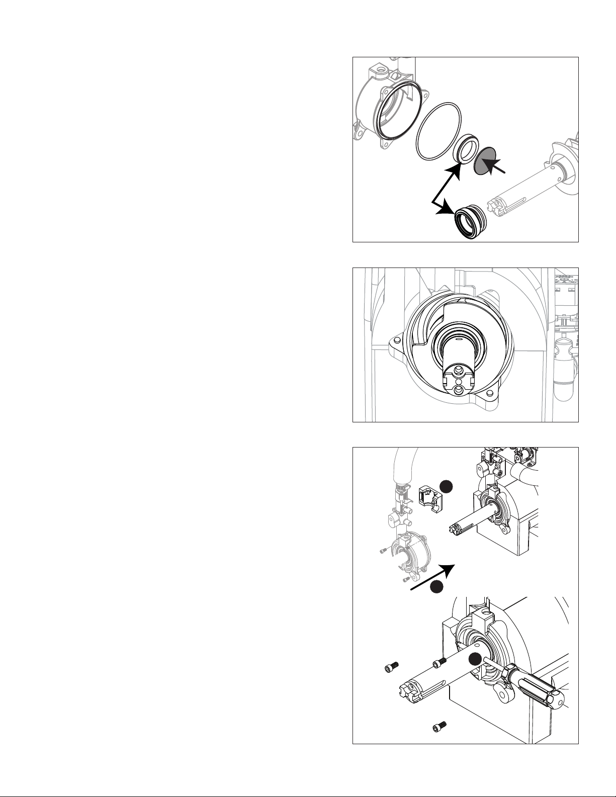
Fig. 19
13. Remove and discard the ceramic mating ring and
shaft seal.
HCD1010R/N, HMF1010R/N, HCD1410R/N, HMF1410R/N 25
Evaporator reassembly
Fig. 20
14. Install ceramic mating ring and shaft seal.
Caution: Do not touch the sealed surface of either
part. Oil from bare skin will cause premature seal
failure.
15. Use liquid hand soap on the rubber part of the
ceramic seal when installing in main housing. Use
supplied cardboard disc to press into recess.
16. Apply liquid hand soap to raised area of auger
shaft and interior rubber portion of shaft seal before
installing seal.
1 7. Clean O ring groove. Lubricate O ring with petrol-gel
and reinstall.
Cardboard
disc
Do NOT
touch!
Fig. 21
18. Carefully install auger.
19. Rotate auger to position shown to clear main housing
stream divider.
Fig. 22
20. Install rear shuttle insulation (Fig. 22.1) and slide
main housing (Fig. 22.2) onto auger.
2 1. When installing new water seal, use screwdriver to
compress the spring (Fig. 22.3), which allows for
easier installation of the three screws.
1
2
3
26 HCD1010R/N, HMF1010R/N, HCD1410R/N, HMF1410R/N
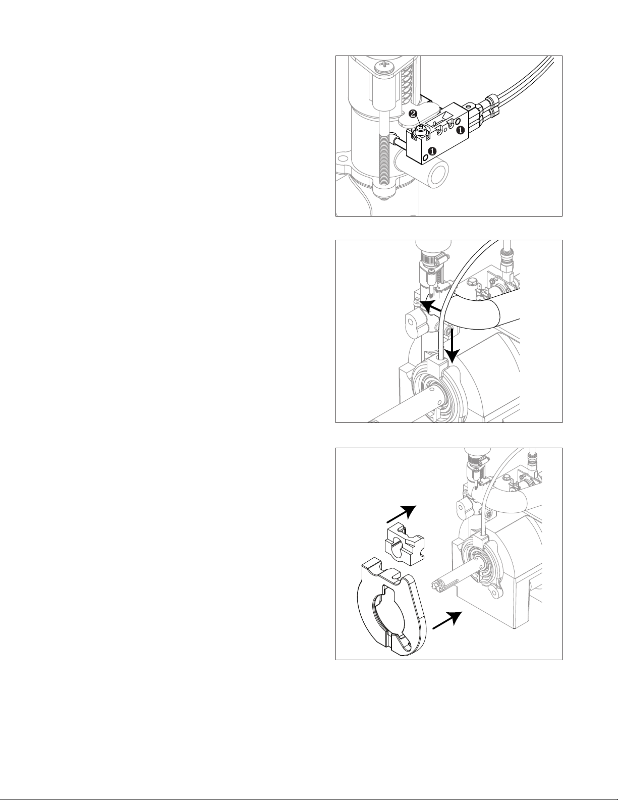
Fig. 23
22. Install shuttle switch.
§ Align holes with pins (Fig. 23.1) and depress switch
button (Fig. 23.2) to clear shuttle tab.
Fig. 24
23. Install shuttle drain tube and front feed water tube
(Fig.24).
Fig. 25
24. Install main housing insulation and shuttle insulation:
25. Apply a coat of petro gel to auger shaft.
HCD1010R/N, HMF1010R/N, HCD1410R/N, HMF1410R/N 27
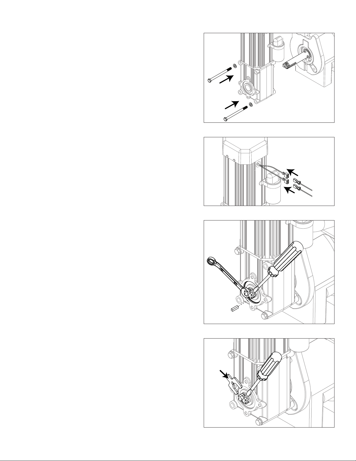
Fig. 26
26. Slide gear motor onto auger and install gear motor
bolts (9/16" wrench).
Fig. 27
2 7. Connect gear motor wires.
Fig. 28
28. Pry auger forward and rotate auger using 1/2" wrench
to align keyways.
29. Insert key fully.
Fig. 29
30. Pry shaft forward to install retainer fork.
28 HCD1010R/N, HMF1010R/N, HCD1410R/N, HMF1410R/N
Fig. 30
3 1. Rotate retainer fork to align screw holes.
32. Install screws to secure retainer fork.
Fig. 31
33. Install gearbox insulation.
Fig. 32
34. Connect transport tube to louvered docking assembly.
HCD1010R/N, HMF1010R/N, HCD1410R/N, HMF1410R/N 29
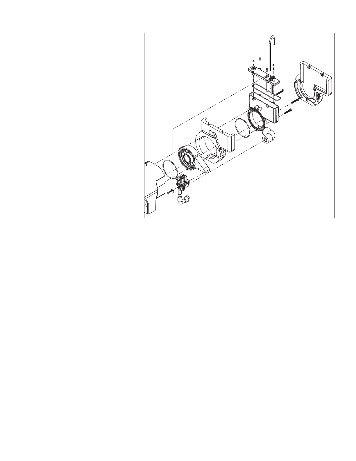
Reservoir/rear bushing disassembly
Fig. 33
1. Press CLEAN button to purge
evaporator. Turn power OFF
when LO WATER lights.
Note: In many applications,
removing the gearmotor,
main housing, and
auger will allow for
the ice machine to be
pulled out further for
better access to rear
components.
2. Slide ice machine forward to
gain access.
3. Use Fig. 32 as disassembly
guide.
Note: Use petrogel when
installing/reinstalling
o-rings.

30 HCD1010R/N, HMF1010R/N, HCD1410R/N, HMF1410R/N
Refrigeration system
Condenser unit operation
The condensing unit is weatherproof and equipped to operate in ambient temperatures from –20 F to 120 F (–29C
to 48.9 C). The condensing unit is controlled by a low pressure control, which works in concert with a refrigerant
solenoid valve on the evaporator module. On start-up, the refrigerant solenoid valve opens and suction pressure
rises above the “on” set point of the control. The compressor and fan turn on and the refrigeration system operates.
Upon shut down, the refrigerant solenoid closes. The compressor will pump down the ice machine evaporator and
suction line until the low “off” set point is reached, at which point the compressor and fan will turn off.
Low ambient operation: Reliable operation at low outdoor ambient temperature is achieved with a pumpdown
cycle, a crankcase heater and a head pressure control valve. When the outdoor ambient falls, the condensing
pressure falls. This causes the discharge pressure to fall as well. When the discharge pressure falls below the dome
pressure, the valve modulates open to the discharge port which allows discharge gas to bypass the condenser.
Mixing the discharge gas with the liquid creates a high pressure at the condenser outlet, reducing the ow and
causing liquid to back up in the condenser. Flooding the condenser reduces the area available for condensing. This
reduction in effective condenser surface area results in a rise in condensing pressure. During summer conditions,
the discharge pressure is high, thus closing the discharge port of the valve. Hence, there is full liquid ow from the
condenser to the receiver.
A check valve is installed in the liquid line between the liquid receiver and the condenser to prevent liquid
migration from the receiver to the condenser during the off cycle. A second check valve is installed in the discharge
outlet of the motor compressor to prevent any oil from migrating onto the compressor head during an off cycle.
A low pressure control will start the condensing unit anytime the low side pressure rises above the C/I setting
of the control. The system contains a crankcase heater which is energized via the contactor of the compressor
during any off cycle. It is de-energized whenever the compressor is energized. This keeps the oil temperature
in the compressor sump warmer than any other wetted surface to prevent liquid migration from settling into the
compressor sump to prevent ooded compressor starts in extreme outdoor temperatures. The liquid receiver
also contains a heater which is controlled by a thermostat to be energized at temperatures below 60°F and
de-energized above 80°F. This is to maintain sufficient refrigerant pressure at extreme outdoor temperatures to
activate the pressure control.
1010 - Refrigerant pressure data
Air-cooled condensers (air) 60 F/16 C 70 F/21 C 80 F/27 C 90 F/32 C 100 F/38 C
Pressure (psig) discharge/suction 202/33 229/35 255/37 275/38 295/39
1410 - Refrigerant pressure data
Air-cooled condensers (air) 60 F/16 C 70 F/21 C 80 F/27 C 90 F/32 C 100 F/38 C
Pressure (psig) discharge/suction 198/31 233/32 268/34 287/36 305/37
HCD1010R/N, HMF1010R/N, HCD1410R/N, HMF1410R/N 31
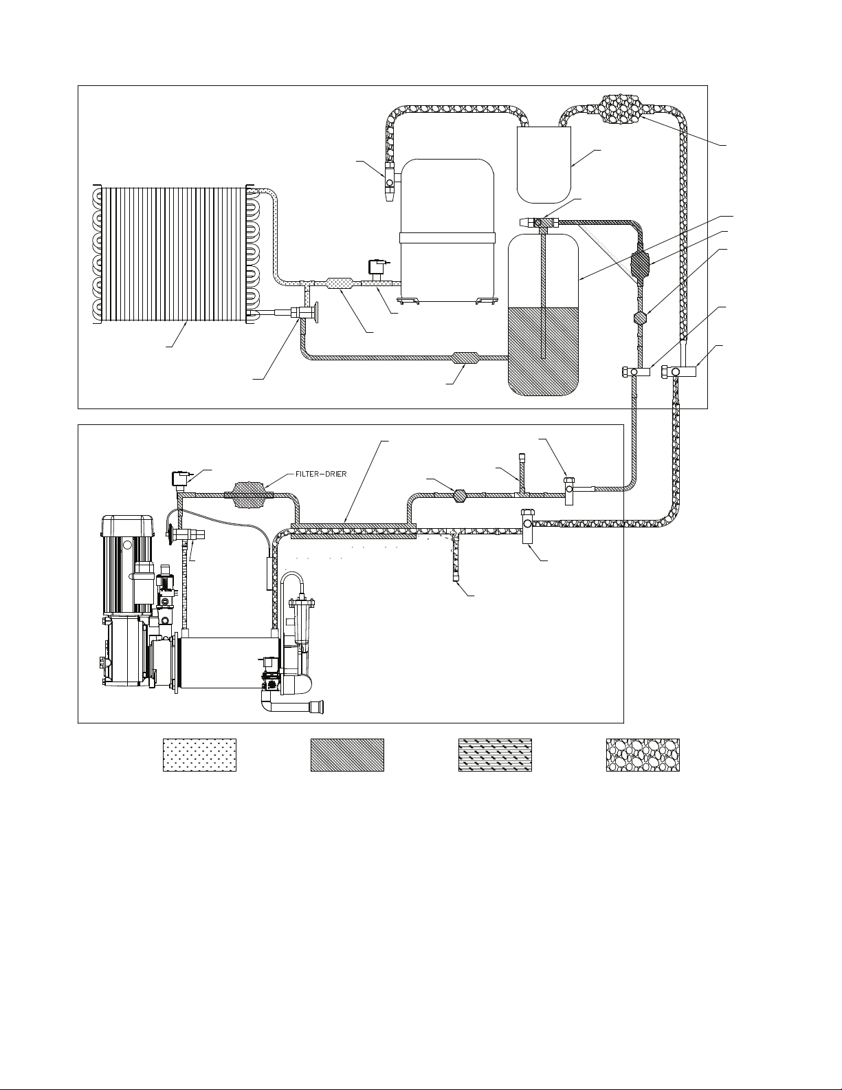
Refrigeration system diagram
EVAPORATOR UNIT
CONDENSER
CONDENSER UNIT
HEAD CONTROL VALVE
CHECK VALVE
COMPRESSOR
LOW SIDE
SERVICE VALVE
W/ SERVICE PORT
RECEIVER
HIGH SIDE
SERVICE VALVE
W/ SERVICE PORT
FILTER-DRIER
SIGHT GLASS
HIGH SIDE
SERVICE VALVE
W/ SERVICE PORT
LOW SIDE
SERVICE VALVE
W/ SERVICE PORT
FILTER
HEAT EXCHANGER
LOW SIDE
SERVICE PORT
LOW SIDE
SERVICE VALVE
W/ SERVICE PORT
HIGH SIDE
SERVICE VALVE
W/ SERVICE PORT
HIGH SIDE
SERVICE PORT
SIGHT GLASS
SOLENOID VALVE
THERMOSTATIC
EXPANSION
VALVE
HIGH SIDE
SERVICE VALVE
W/ SERVICE PORT
LOW PRESSURE VAPORLOW PRESSURE LIQUIDHIGH PRESSURE LIQUID
HIGH PRESSURE VAPOR
CHECK VALVE
SUCTION
ACCUMULATOR
HIGH PRESSURE SWITCH

32 HCD1010R/N, HMF1010R/N, HCD1410R/N, HMF1410R/N
Refrigeration charge
All service on refrigeration systems must be performed in accordance with all federal, state and local laws. It is the
responsibility of the technician to ensure that these requirements are met. Recharging ice machine to other than
factory specications will void the warranty.
R404A Ice Machine Charge Specications
Line Run Total Charge 1010/1410 (Tecumseh) Total Charge 1410R three phase
(Larkin)
0 - 100' (0 - 30.5 m) 12.5 lb (5.7 kg) 8.5 lb (3.9 kg)
100’ + (30.5 m+) not recommended – consult factory
Note: Condensing unit shipped with 0.5 lb R404A charge.
Refrigerant replacement requirements
1. Non-contaminated refrigerant removed from any Follett refrigeration system can be recycled and returned to
the same system after completing repairs. Recycled refrigerant must be stored in a clean, approved storage
container. If additional refrigerant is required, virgin or reclaimed refrigerant that meets ARI standard 700-88
must be used.
2. In the event of system contamination (for example, a compressor burn out, refrigerant leak, presence of
non-condensibles or moisture), the system must be repaired, evacuated and recharged using virgin or
reclaimed refrigerant that meets ARI standard 700-88.
3. Follett LLC does not approve of recovered refrigerants. Improper refrigeration servicing procedures will void
the factory warranty.
Evacuation
Evacuate the system to a level of 500 microns. When the 500 micron level is reached, close all valves. Allow the
system to sit for approximately 20 minutes. During this period the system pressure should not rise. If the system
pressure rises and stabilizes there is moisture in the system and further evacuation is needed. If the pressure
continues to rise check the system for leaks.

HCD1010R/N, HMF1010R/N, HCD1410R/N, HMF1410R/N 33
Evaporator Unit Low-side or ice making head
Ambients Minimum Maximum
Air temperature 50 F/10 C 100 F/37.8 C
Water temperature
1
45 F/7 C 90 F/32.2 C
1
Ambient water temperature is measured in the ice machine water reservoir.
Ice capacity test
Ice machine production capacity can only be determined by weighing ice produced in a specic time period.
1. Replace all panels on ice machine.
2. Disconnect the drain solenoid.
3. Run ice machine for at least 15 minutes.
4. Weigh and record weight of container used to catch ice.
5. Catch ice for 15 or 20 minutes.
6. Reconnect the drain solenoid.
7. Weigh harvested ice and record total weight.
8. Subtract weight of container from total weight.
9. Convert fractions of pounds to decimal equivalents (ex. 6 lbs 8oz = 6.5 lbs).
10. Calculate production using following formula:
1440 min. x wt. of ice produced
Total test time in minutes
=
Production capacity/24 hr.
11. Calculated amount per 24 hours should be checked against rated capacity for same ambient and water
temperatures in Ice Production Tables.
34 HCD1010R/N, HMF1010R/N, HCD1410R/N, HMF1410R/N
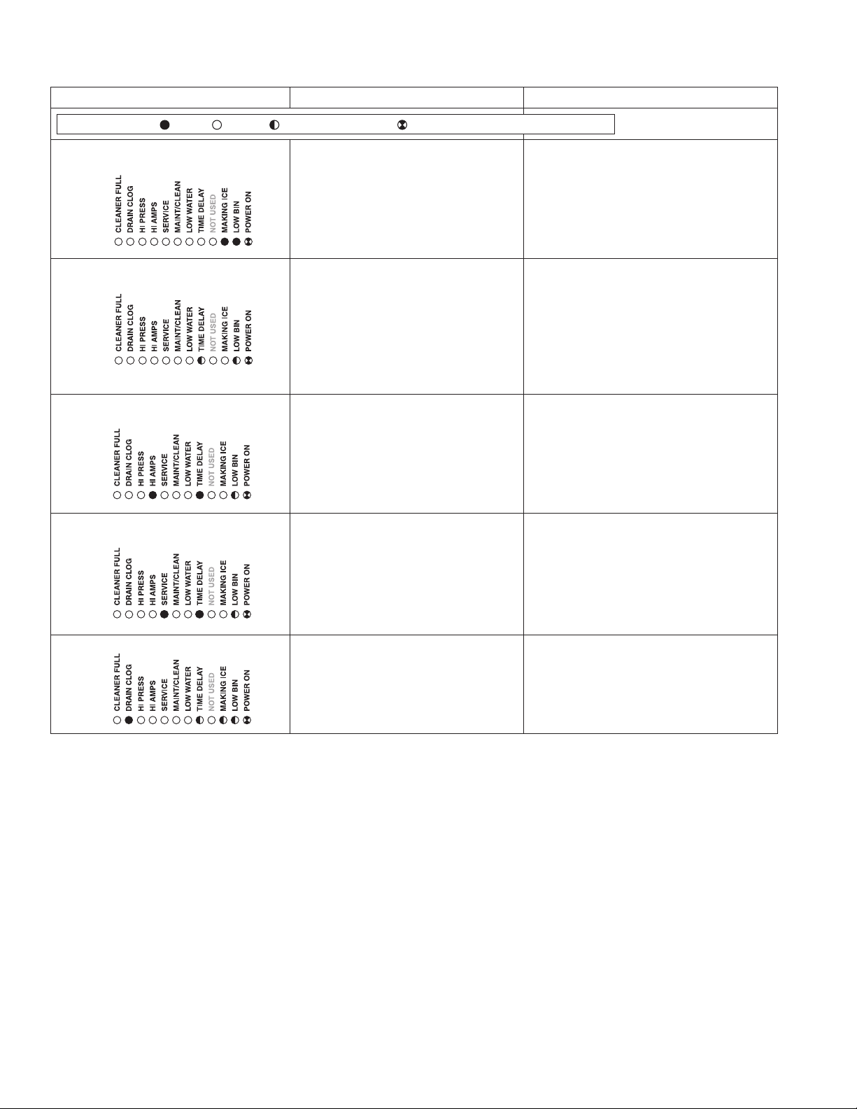
Troubleshooting
Please see “Service” section for a description of each function.
Ice machine disposition Possible causes Corrective action
FLASHINGON or OFF
Legend:
OFFON
1. Ice machine is in running
condition but not making ice.
.
1. No output from PC board.
2. Defective start relay.
3. Defective start capacitor.
4. Defective run capacitor.
5. Defective main contactor.
6. Defective compressor.
1. Replace PC board.
2. Replace start relay.
3. Replace start capacitor.
4. Replace run capacitor.
5. Replace main contactor.
6. Replace compressor.
2. Machine in TIME DELAY without full
bin.
1. Ice jamming due to improperly
installed transport tube causing a
false shuttle.
2. Shuttle stuck in up position.
3. Damaged or improperly installed
thermostat (open).
4. Transport tube backed-out of
coupling.
1. Correct transport tube routing.
2. Repair or replace shuttle mechanism.
3. Replace or reposition thermostat.
4. Correct coupling installation.
3. Ice machine is not making ice.
HI AMPS.
.
1. Poor water quality causing ice to jam
auger.
2. Damaged shuttle mechanism.
3. Intermittent drive output from
PC board. Evaporator will freeze
causing a HI AMPS error.
4. Gearmotor is unplugged.
1. Clean ice machine. Increase
ushing frequency. Position TDS switch
to High TDS setting.
2. Replace or repair shuttle
mechanism.
3. Replace PC board.
4. Plug in gearmotor.
4. Ice machine is not making ice.
SERVICE.
.
1. Internal water leak touching chassis
sensor.
1. Identify and repair leak. Clean/dry
chassis and sensors and restart
machine.
5. Drain clog.
.
1. Improper ow in drain system. 1. Correct/clean drain system.
HCD1010R/N, HMF1010R/N, HCD1410R/N, HMF1410R/N 35
Ice machine disposition Possible causes Corrective action
FLASHINGON or OFF
Legend:
OFFON
6. Ice machine is making ice.
Excessive water in bin or
coming into bin from transport
tube.
1. Failed water sensors. Processor
assumes there is no water when
there is water.
2. Blocked reservoir vent.
3. Defective water feed solenoid
valve. Stuck in open position.
1. Clean or replace water probe
assembly. Check wiring
connections.
2. Clean or replace vent tubes.
3. Replace water feed solenoid
valve.
7. Ice machine is not making ice.
Lo water.
1. Water supply is insufficient.
2. Low water pressure.
3. Defective water feed solenoid
valve. Stuck in closed position.
4. No water feed output from
PC board.
5. Plugged screen on inlet side of
ll solenoid.
6. Plugged check valve.
1. Restore water supply and check
water lters. If evaporator was
completely empty the reset button
may have to be pressed to restart
the ice machine.
2. Ice machine will eventually start
when water reaches normal lo level.
3. Replace water feed solenoid valve.
4. Replace PC board.
5. Remove and clean screen.
6. Remove and clean.
8. Blinking Lo water, power, time
delay.
Machine did not see water
consumption while trying to make
ice.
1. Lack of refrigeration/low
refrigerant charge/leak.
2. Debris shorting reservoir probes.
1. Verify refrigerant pressures,
compressor running, sight glass
clear.
2. Clean probes and reservoir of
debris.
ATTENTION!
To prevent circuit breaker overload, wait 5 minutes before restarting
this unit. This allows the compressor to equalize and the evaporator
to thaw.
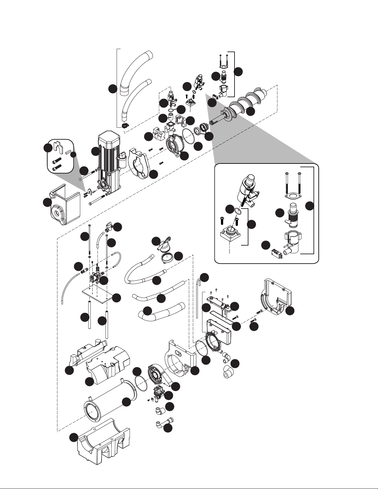
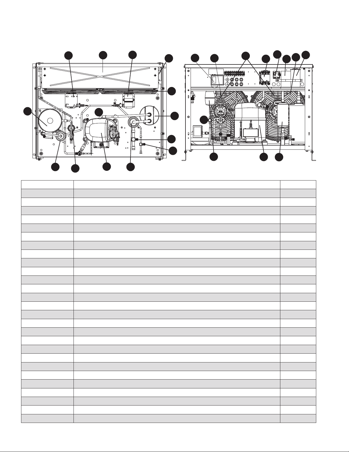
36 HCD1010R/N, HMF1010R/N, HCD1410R/N, HMF1410R/N
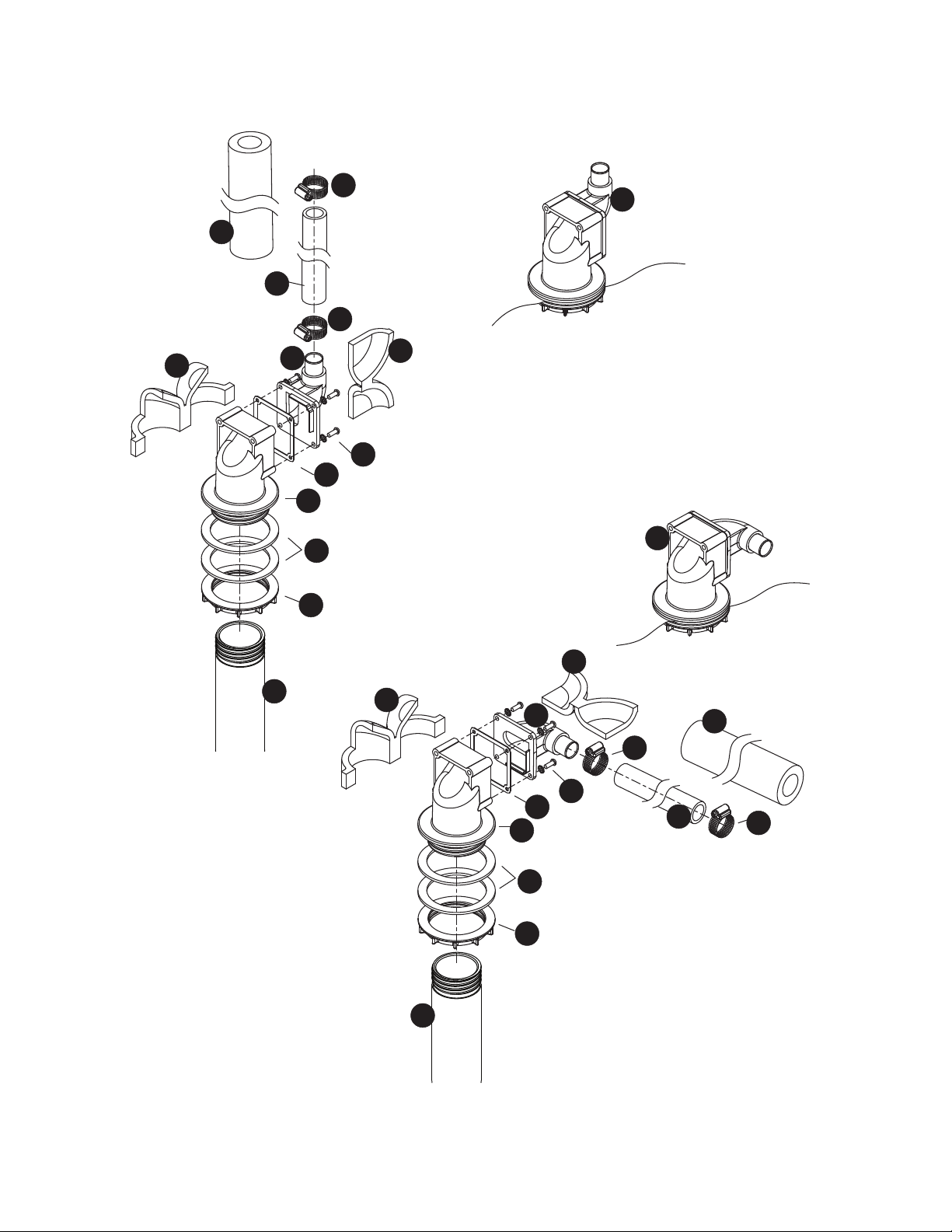
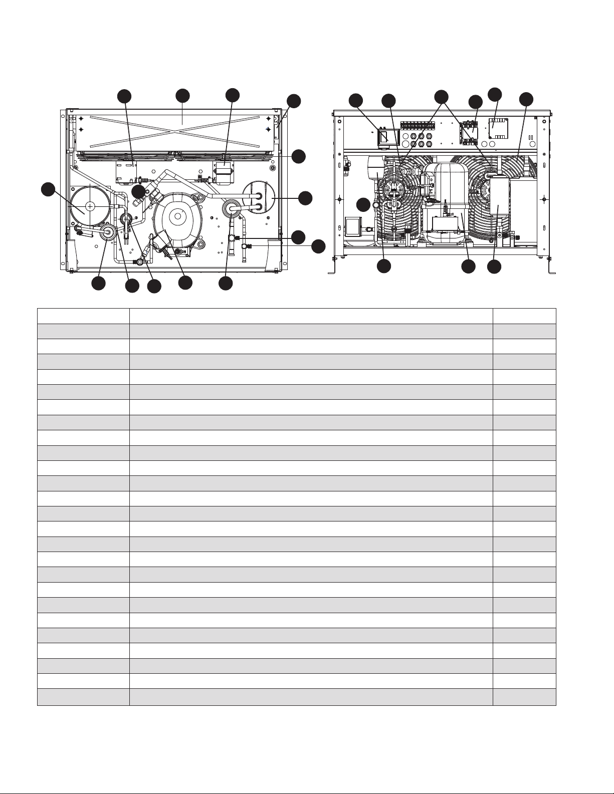
Replacement parts
Evaporator assembly (Before Serial Number K81440)
1
3
21
14
13
12
11
9
29
7
8
20
15
16
18
22
23
13
31
31
31
31
31
19
13
24
25
26
28
28
4
5
10
2
31
17
17
17
17
17
35
34
33
36
6
30
32
27
3
37
10
2
2
2
31
31
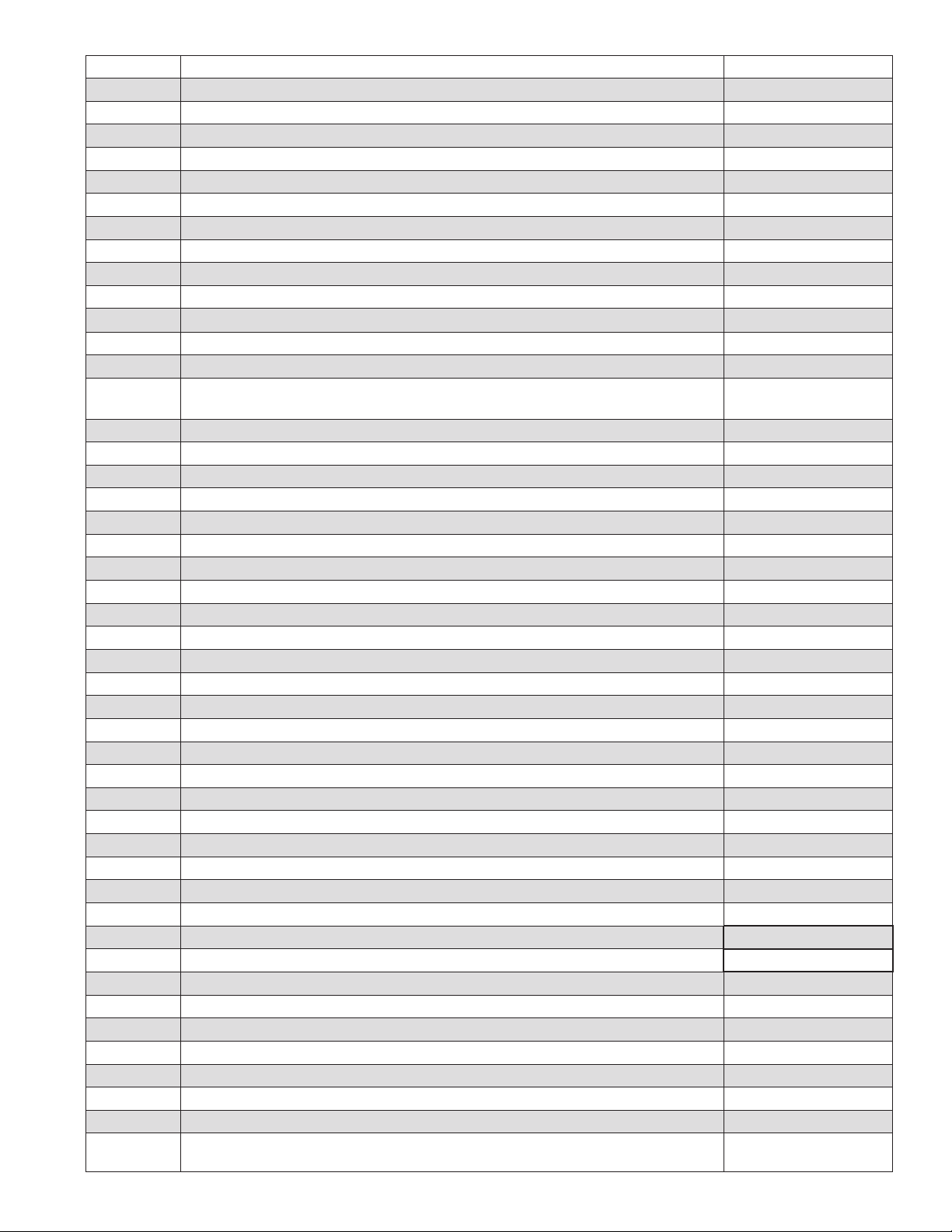
HCD1010R/N, HMF1010R/N, HCD1410R/N, HMF1410R/N 37
Reference # Description Part #
1 Tube, ice transport, insulated 01118 18 1
2 Shuttle assembly 01118 13 2
2 Shuttle assembly, IMDV 01118 14 0
3 Switch, shuttle 01006261
4 Compression nozzle 01278654
5 O-ring, shuttle 01164920
6 Screw, reservoir (3 required) 206395
7 Auger hardware (includes screws, key, retainer) 01175587
8 Key 01164938
9 Bolt, gearmotor mounting (2) (remote condensing units), includes washers 01125012
10 Cartridge assembly, shuttle spring 01118033
10 Cartride, shuttle spring, IMDV 01118041
11 Gearmotor, 120 V (includes capacitor) 01132307
12 Main housing (Ice machines with serial numbers before J771797 require a new
compression nozzle also)
01117977
13 O ring 01301720
14 Seal, auger shaft 01302249
15 Cup, sanitizer 01164995
16 Cap, sanitizer 01118637
Not shown Tubing, water, 3/8" OD 502719
Not shown Tubing, water, 1/4" OD 502079
17 Retainer kit, evaporator 01118652
18 Solenoid, water feed (120 V) 01223015
19 Reservoir lid and sensors (includes screws and o-ring) 01118 108
20 Valve, shut-off, water 502921
21 Auger, 1010 remote condensing (includes seal, key, and auger hardware) 01117944 (1010 only)
21 Auger, 1410 remote condensing (includes seal, key, and auger hardware) 01117951 (1410 only)
22 Evaporator, 1010 01118066 (1010 only)
22 Evaporator, 1410 01118074 (1410 only)
23 Rear bushing housing and bushing (includes (1) o-ring) 01118082
24 Reservoir assembly, water (includes lid) 01118 116
25 Tube, vent (17" required) 502079
26 Tube, sanitizer 01118660
27 Kit, MicroChewblet 01161843
28 Tube, shuttle drain, insulated 01118678
29 Insulation, gearbox, 120 V
01333780
30 Solenoid, purge, 120 V 01222702
31 Insulation kit, 1010 evaporator/reservoir 01302256 (1010 only)
31 Insulation kit, 1410 evaporator/reservoir 01302264 (1410 only)
32 Check valve 01122381
33 Tube, drain, reservoir, insulated 01118 12 4
34 Tube, drain, 1010 01302272 (1010 only)
35 Tube, drain, 1410 01302280 (1410 only)
36 O-ring, reservoir lid 01302298
Not shown Kit, scale (includes reservoir, purge solenoid, drain tubes and tting) 01122662
37 O-ring, MicroChewblet 01161850
Not shown Drain kit (includes 2 ft. x 1" OD silicone tubing, 3/4" x 1" slip, 3/4" barb 3/4" FPT
(2), 3/4" barb x 3/4" FPT elbow)
01210350
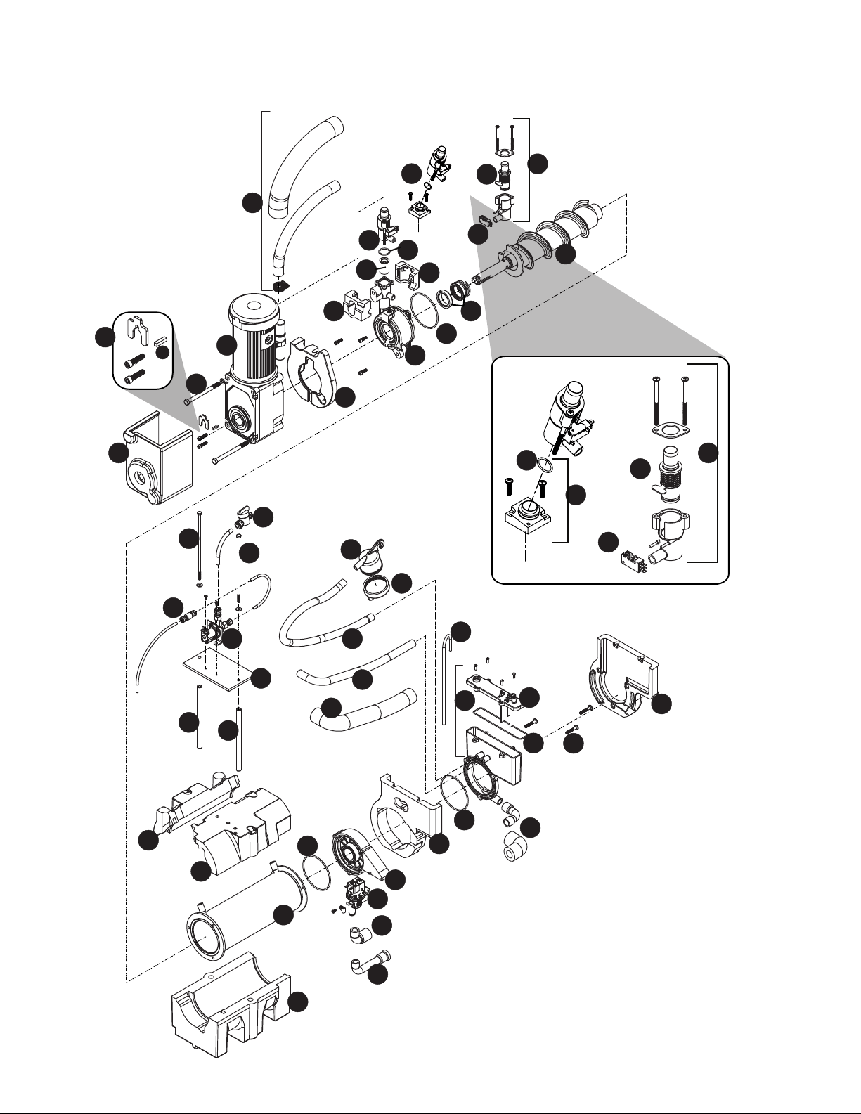
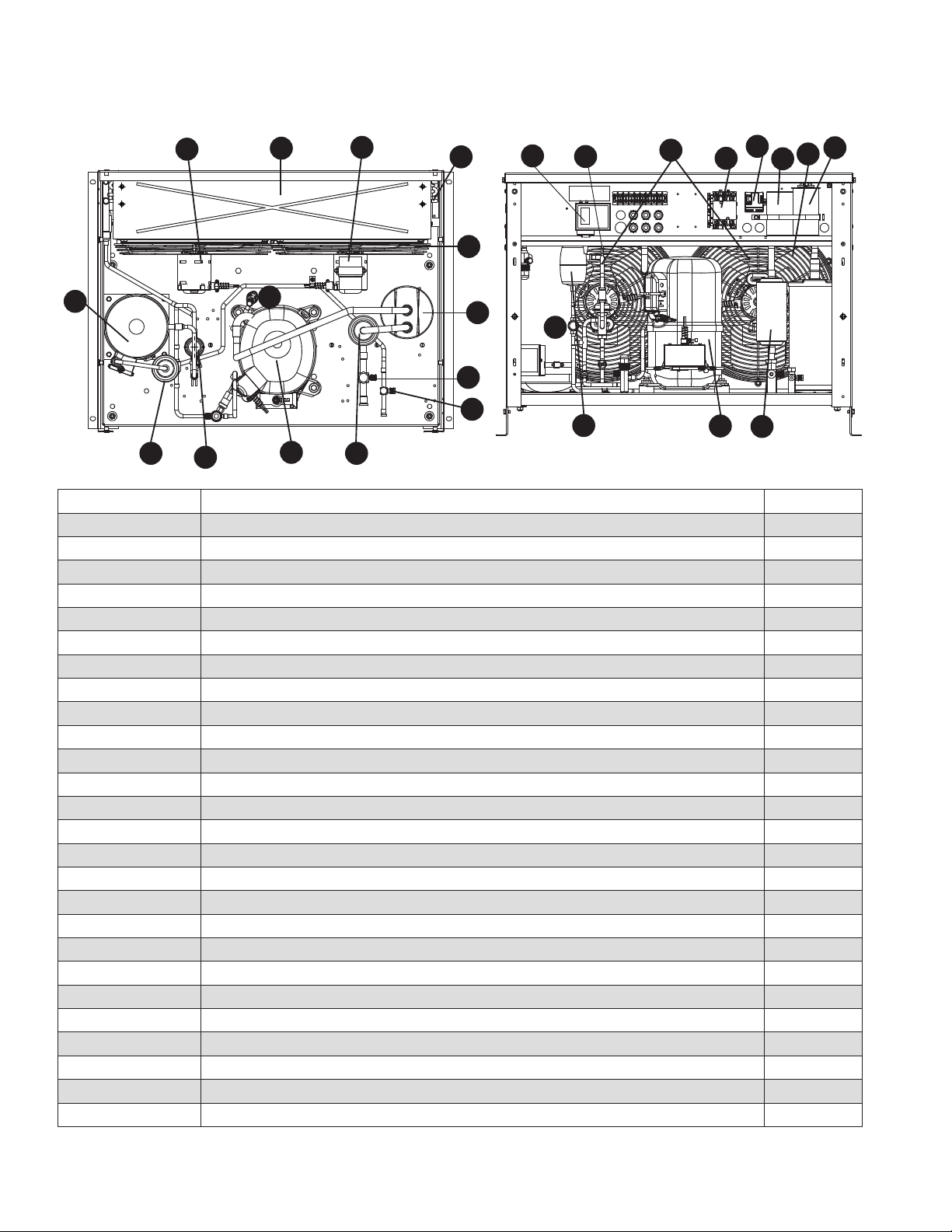
38 HCD1010R/N, HMF1010R/N, HCD1410R/N, HMF1410R/N
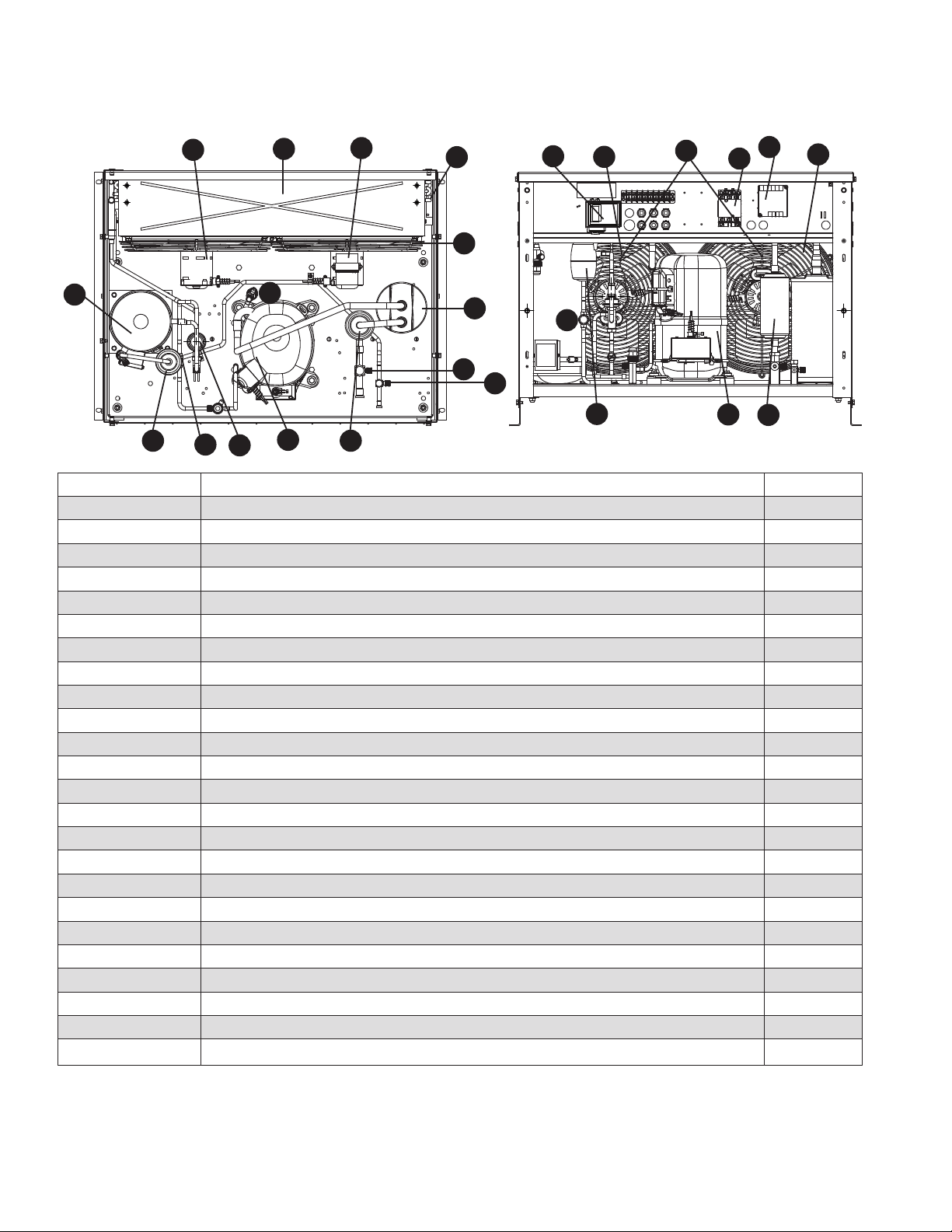
Replacement parts
Evaporator assembly (After Serial Number K81439)
1
3
21
14
13
12
11
9
29
7
8
20
15
16
18
22
23
13
31
31
31
31
31
19
13
24
25
26
28
28
4
5
10
2
31
17
17
17
17
17
35
34
33
36
6
30
32
2
2
27
3
37
10
2
31
31
HCD1010R/N, HMF1010R/N, HCD1410R/N, HMF1410R/N 39
Reference # Description Part #
1 Tube, ice transport, insulated 01118 18 1
2 Shuttle assembly 01118 13 2
2 Shuttle assembly, IMDV 01118 14 0
3 Switch, shuttle 01006261
4 Compression nozzle 01278654
5 O-ring, shuttle 01164920
6 Screw, reservoir (10 pack)
01333830
7 Auger hardware (includes screws, key, retainer) 01118 6 11
8 Key 01164938
9 Bolt, gearmotor mounting (2) (self-contained units), includes washers 01118629
10 Cartridge assembly, shuttle spring 01118033
10 Cartridge, shuttle spring, IMDV 01118041
11 Gearmotor, 120 V (includes capacitor) 01275056
12 Main housing 01117969
13 O ring 01301720
14 Seal, auger shaft 01302249
15 Cup, sanitizer 01164995
16 Cap, sanitizer 01118637
Not shown Tubing, water, 3/8" OD 502719
Not shown Tubing, water, 1/4" OD 502079
17 Retainer kit, evaporator 01118652
18 Solenoid, water feed (120 V)
01223015
19 Reservoir lid and sensors (includes screws and o-ring) 01118 108
20 Valve, shut-off, water 502921
21 Auger, 1010 (includes seal, key, and auger hardware) 01117928 (1010 only)
21 Auger, 1410 (includes seal, key, and auger hardware) 01117936 (1410 only)
22 Evaporator, 1010 01118066 (1010 only)
22 Evaporator, 1410 01118074 (1410 only)
23 Rear bushing housing and bushing (includes (1) o-ring) 01118082
24 Reservoir assembly, water (includes lid) 01118 116
25 Tube, vent (17" required) 502079
26 Tube, sanitizer 01118660
27 Kit, MicroChewblet 01161843
28 Tube, shuttle drain, insulated 01118678
29 Insulation, gearbox 01165240
30 Solenoid, purge, 120 V
01337286
31 Insulation kit, 1010 evaporator/reservoir 01302256 (1010 only)
31 Insulation kit, 1410 evaporator/reservoir 01302264 (1410 only)
32 Check valve 01122381
33 Tube, drain, reservoir, insulated 01118 12 4
34 Tube, drain, 1010 01302272 (1010 only)
35 Tube, drain, 1410 01302280 (1410 only)
36 O-ring, reservoir lid 01302298
Not shown Kit, scale (includes reservoir, purge solenoid, drain tubes and tting) 01122662
37 O-ring, MicroChewblet 01161850
Not shown Drain kit (includes 2 ft. x 1" OD silicone tubing, 3/4" x 1" slip, 3/4" barb 3/4" FPT
(2), 3/4" barb x 3/4" FPT elbow)
01210350
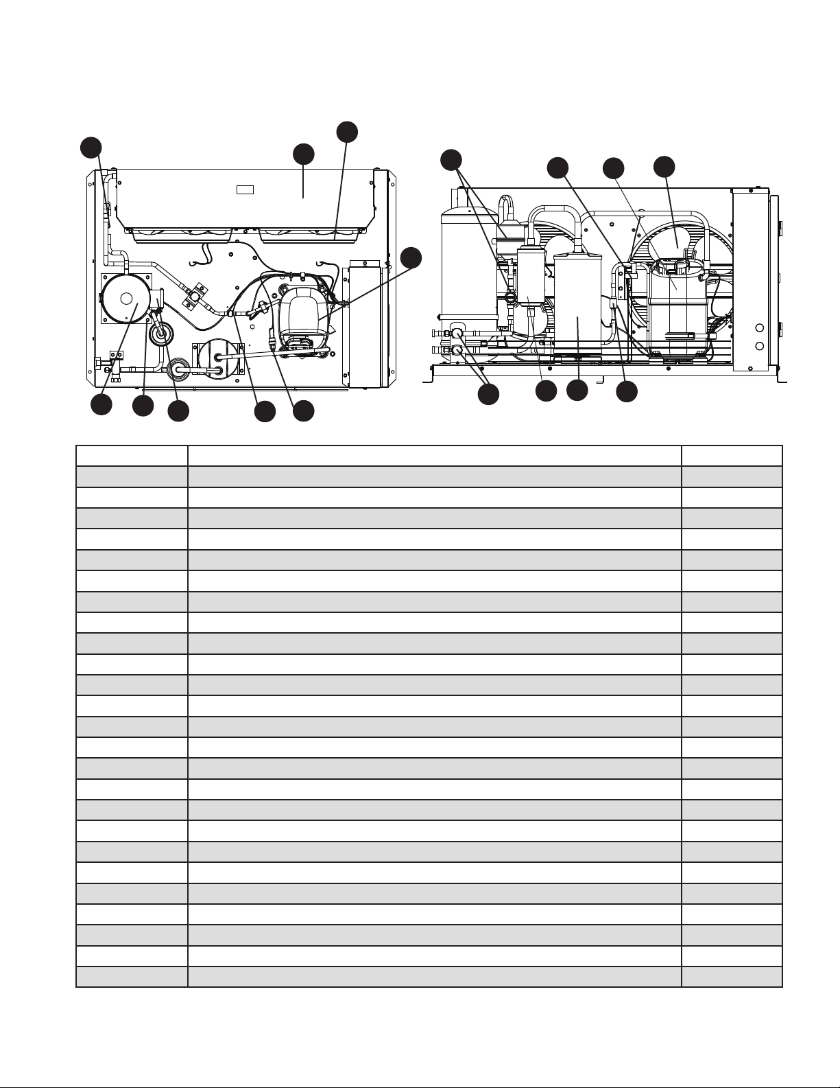
40 HCD1010R/N, HMF1010R/N, HCD1410R/N, HMF1410R/N
2
11
1
4
6
5
3
8
12
7
10
6
9
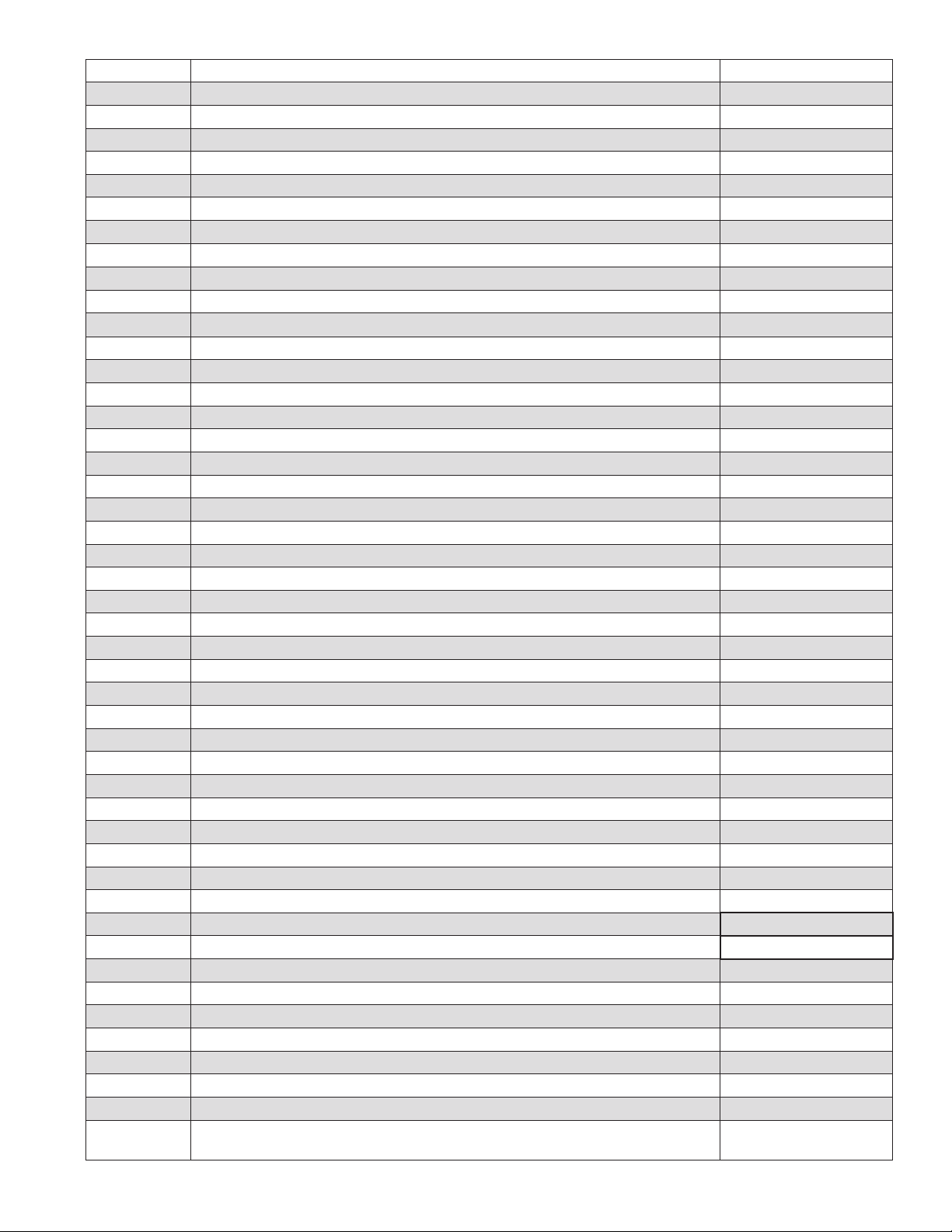
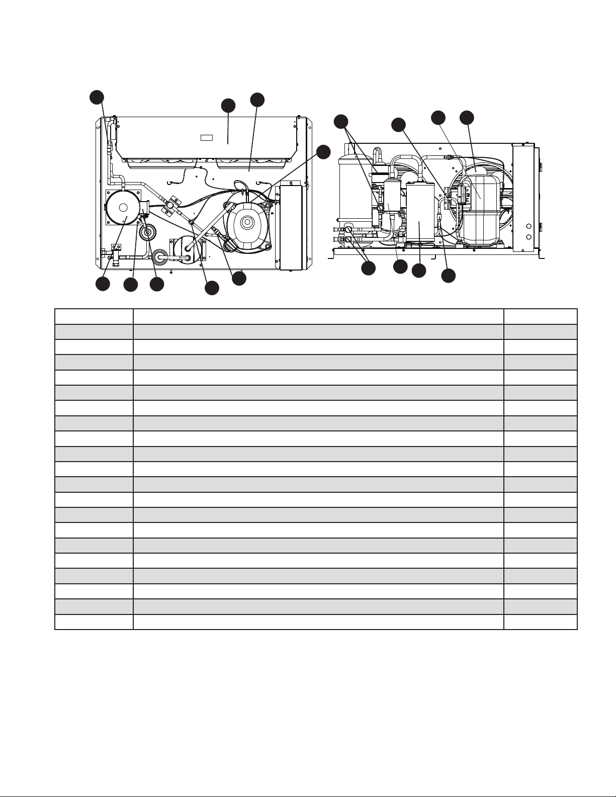
Low-side assembly
HCD1010R/N, HMF1010R/N, HCD1410R/N, HMF1410R/N 41
Reference # Description Part #
1 Tubing, liquid line (includes insulation) 01071448
2 Tubing, suction line (includes insulation) 01121391
3 Sight glass 01165570
4 Electrical box support 01121292
5 Valve, expansion, thermal (includes TXV insulation) 01118942
6 Insulation, TXV (bulb and body) 502830
7 Valve, shut-off, liquid line 00107060
8 Kit, liquid line solenoid (Includes lter drier) 01191493
9 Valve, shut-off, suction line 00107078
10 Base, split system
01333772
11 Insulation, service valve 01121284
12 Heat Exchanger 01121409
42 HCD1010R/N, HMF1010R/N, HCD1410R/N, HMF1410R/N
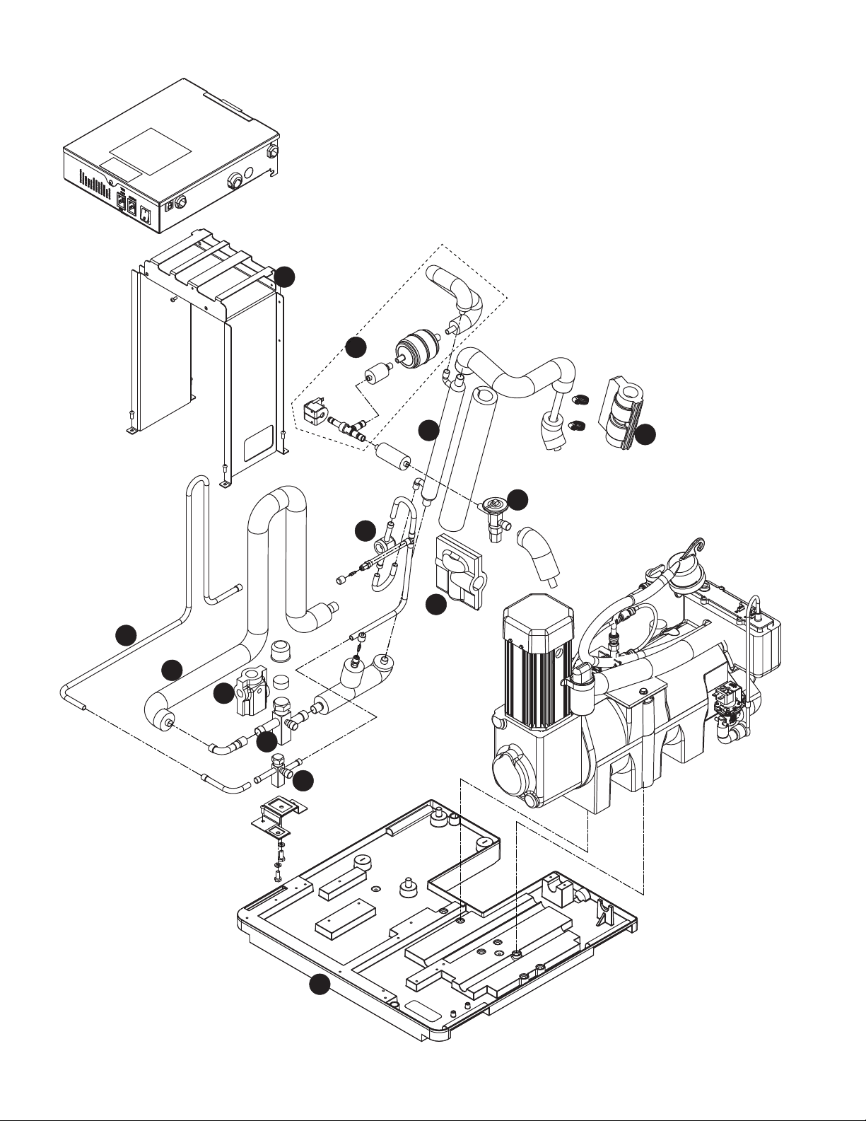
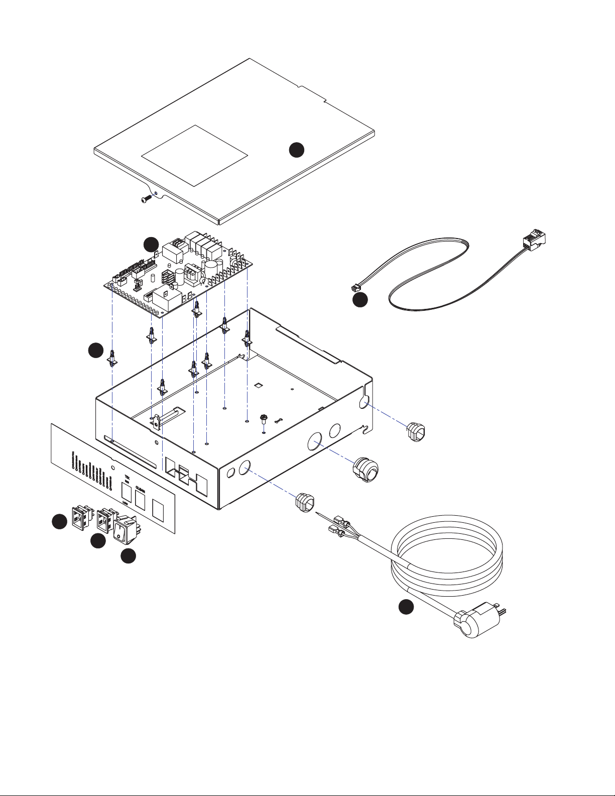
Electrical box
1
7
4
3
2
8
6
5

HCD1010R/N, HMF1010R/N, HCD1410R/N, HMF1410R/N 43
Reference # Description Part #
1 Cover, electrical box, air/water-cooled 01118975
2 Board, control, 120 V (includes stand-offs) 01117829
3 Stand-offs (set of 8) 00130906
4 Switch, TDS 01165695
5 Switch, evaporator clean 01165703
6 Switch, ice machine power 01165711
7 Cord, power, 120 V 011114 9 1
8 Cable, IMDV 01302983
44 HCD1010R/N, HMF1010R/N, HCD1410R/N, HMF1410R/N
Integration kit – top-mount and RIDE remote ice delivery
1
11
2
2
13
10
12
4
5
7
8
12
1
11
10
2
9
4
5
6
7
8
2
6
3
3
RIDE model configuration
Top mount configuration
14
14
HCD1010R/N, HMF1010R/N, HCD1410R/N, HMF1410R/N 45
Reference # Description Part #
1 Shuttle actuator 00171322
2 Clamp 500377
3 Actuator elbow (includes 00167122 and 209100) 00171264
4 Screws 01303064
5 Gasket 01303072
6 Actuator body 00171272
7 Gasket, coupling 01303080
8 Ring, locking (includes 00126532) 00171371
9 Ice transport tube, 10' (3 m) 00171280
9 Ice transport tube, 20' (6 m) 00171298
10 Insulation, transport tube 501176
Not shown Insulated polywire ice transport tube, per foot 00174896
11 Insulation, elbow 01303098
12 Insulation, actuator 01303106
13 Ice transport tube, top mount, 30" (762 mm) 00171306
14 Extension-ll tube, 9" 01303114
14 Extension-ll tube, 4" 01303122
Not shown Integration kit, top mount, Harmony or Bin 00171389
Not shown Integration kit, RIDE model, Harmony or Bin, (includes 10' (3 m) of tube and
insulation)
00171397
Not shown Integration kit, drop in 00145334
Not shown Integration kit, Cornelius PR150 00144774
Not shown Integration kit, Vision (does not include ice tube) 00997171
Not shown
Diverter plate (single agitator Cornelius dispensers and left-hand dispense chute on
dual-agitator Cornelius dispensers)
01303130
Not shown
Diverter plate (right-hand dispense chute on dual-agitator dispensers) 00996207
Not shown SafeCLEAN Plus, case of 6 01149954
Not shown SafeCLEAN Plus, case of 24 01149962
Not shown Sani-Sponge kit 00132068
Not shown High-capacity lter system 01303148
Not shown Primary lter (1)
01333814
Not shown Primary lter (6) 00978973
Not shown Pre-lter (1)
01333822
Not shown Pre-lter (12) 00954305
Not shown IMSII or IMSIII sanitizer concentrate - 16 oz. 00979674
Not shown Sponge, sanitary, pack of 24 01075431
Not shown Kit, IMDV (included IMDV cartridge and communication cable) 01116 177
Not shown Tubing, silicone (per foot) 01303155
46 HCD1010R/N, HMF1010R/N, HCD1410R/N, HMF1410R/N
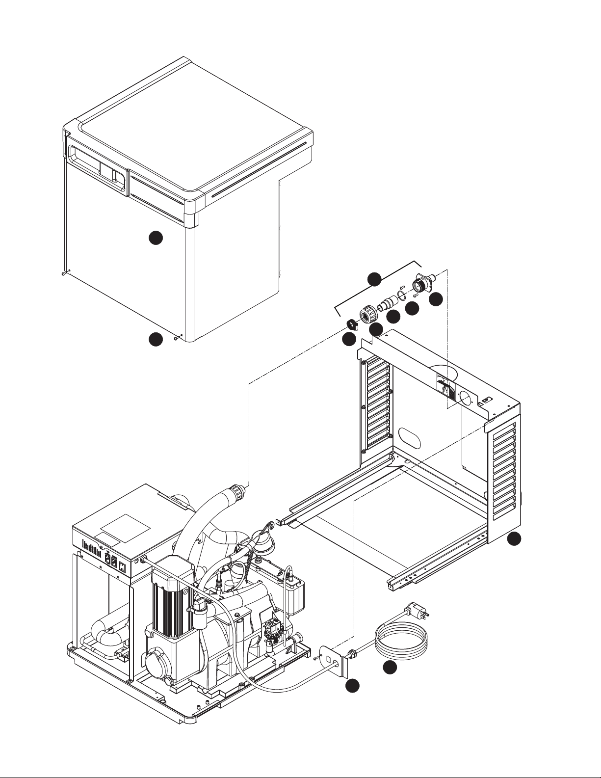
Skins assembly
10
5
4
3
6
8
7
11
9
2
1
HCD1010R/N, HMF1010R/N, HCD1410R/N, HMF1410R/N 47
Reference # Description Part #
1 Cover, front 01121417
2 Coupling (includes O-ring) 00171207
3 O-ring 01303171
4 Bulkhead tting 00171215
5 Catp, nut, ice hose 01303189
6 Hose clamp 500377
7 Plate, strain relief 00192070
8 Louvered docking assembly, 1010 (includes strain relief plate, bulkhead
tting)
01121425 (1010 only)
8 Louvered docking station, 1410 (includes strain relief plate, bulkhead
tting)
01121433 (1410 only)
9 Screw 01303197
10 Bulkhead connector kit 00171223
11 Cord and plug, power 011114 9 1
Not shown Fitting, drain 00109728
48 HCD1010R/N, HMF1010R/N, HCD1410R/N, HMF1410R/N
6
17
7
3
8
13
7
8
13
4
1
4
2
5
9
10
11
5
15
14
12
16
19
12
18
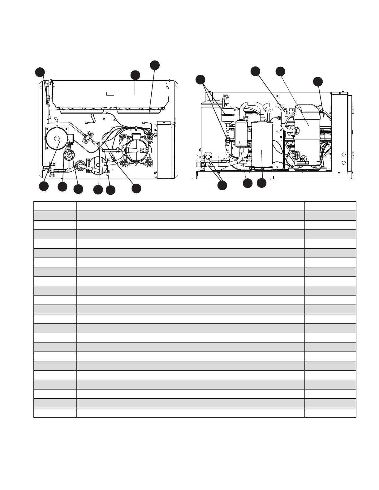
20
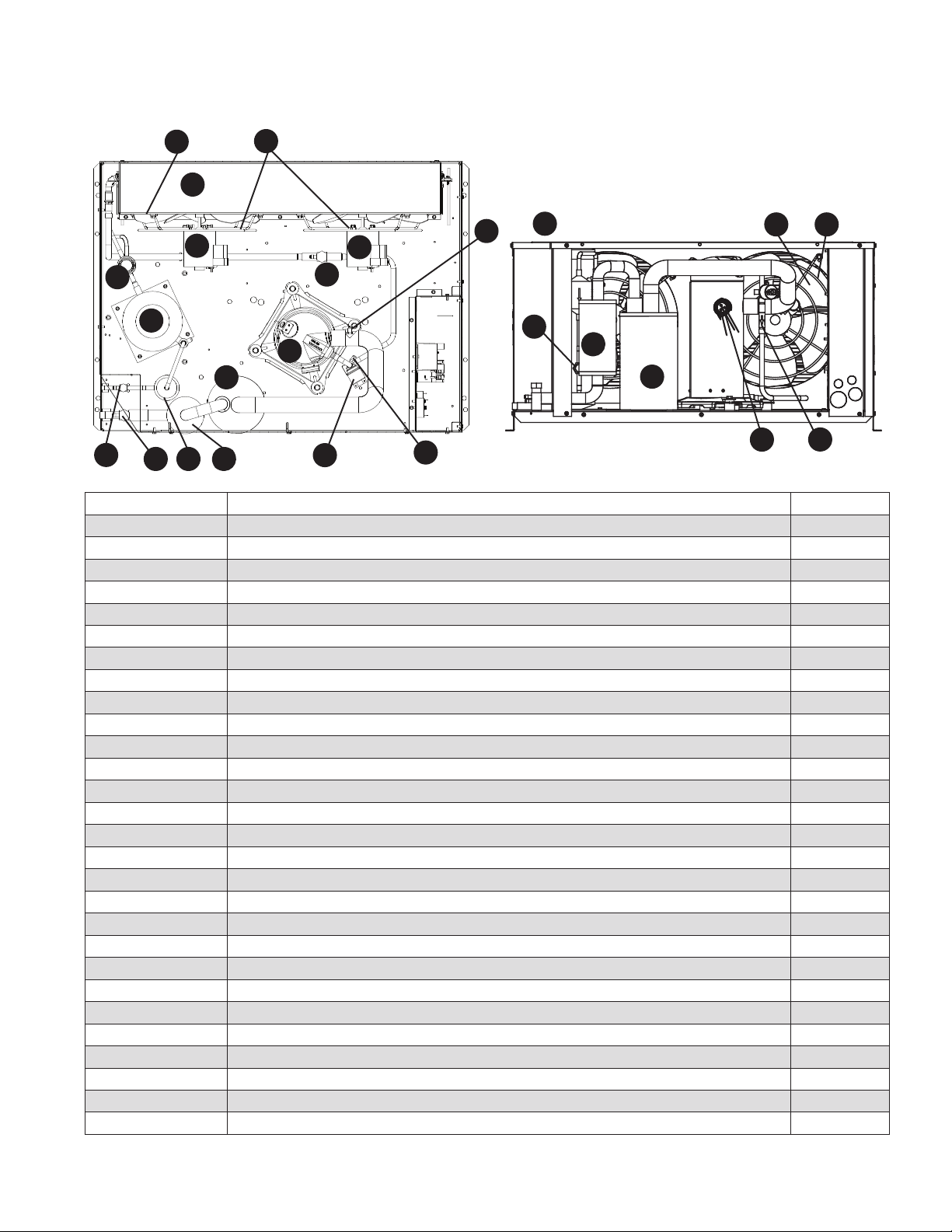
1010 Single-phase condensing unit (AJA7490ZXDPN - Tecumseh))
Reference # Description Part #
1 Shroud 01018290
2 Condenser 01018324
3 Head pressure control valve 01021401
4 Condenser fan motor 01018266
5 Condenser fan guard 00123067
6 Receiver 01122514
7 Filter drier, liquid 01122522
8 Compressor (includes start and run capacitors, relay, suction and liquid drier) 01122605
9 Shut-off valve, suction line 00107078
10 Shut-off valve, liquid line 00107060
11 Sight glass 01018357
12 Condenser fan blade 00173088
13 Filter drier, suction 00991075
14 Low pressure control 01018316
15 Contactor 00155952
16 Starting Relay 00173021
17 Suction valve 01122530
18 Run capacitor 00141689
19 Starting capacitor 01036748
20 Accumulator, suction, insulated 01122506
Not shown Check valve 00175893
Not shown High pressure switch 01018308
Not shown Fan cycling switch 01021393
Not shown Crankcase heater 00185827
Not shown Overload 01036722
Not shown Heater, receiver 01076942
Not shown Thermostat, heater, receiver 01122548
Top View
Side View
HCD1010R/N, HMF1010R/N, HCD1410R/N, HMF1410R/N 49
1010 Single-phase condensing unit (ASFR9510ZNAMC1 - Tecumseh)
Reference # Description Part #
1 Shroud & micro-channel condenser assembly 01353754
2 Head pressure control valve 01353762
3 Condenser fan motor 01353770
4 Condenser fan blade 01353788
5 Receiver 01122514
6 Reciever heater 01076942
7 Thermostat 01122548
8 Kit, liquid lter drier and sight glass 01353796
9 Low pressure switch 01018316
10 High pressure switch 01018308
11 Kit, service valves (5/8” & 1/2”) 01353804
12 Suction lter 01353812
13 Accumulator 01353820
14 Compressor 01353838
15 Compressor crankcase heater 00185827
16 Discharge thermostat 01353853
17 Check valve 01353861
Not shown Relay 00173021
Not shown Contactor & heater switch CTK-03
Not shown Run capacitor 00141689
Not shown Start capacitor 01036748
Not shown Receiver, heater and thermostat kit 01353846
Not shown Compressor overload K90-156
Not shown Compressor overload spring 26057
Not shown Compressor overload adapter 40651-1
2
17
7
8
13
4
1
3
5
9
10
11
15
14
12
16
6
Top View
Side View
50 HCD1010R/N, HMF1010R/N, HCD1410R/N, HMF1410R/N
6
17
7
3
8
13
7
8
13
4
1
4
2
5
9
10
11
5
15
14
12
16
19
12
18
20
1410 Single-phase condensing unit (AWA9513ZXDPN - Tecumseh)
Reference # Description Part #
1 Shroud 01018290
2 Condenser 01018324
3 Head pressure control valve 01021401
4 Condenser fan motor 01018266
5 Condenser fan guard 00123067
6 Receiver 01122514
7 Filter drier, liquid 01122522
8 Compressor (includes start and run capacitors, relay, suction and liquid drier) 01122639
9 Shut-off valve, suction line 00107078
10 Shut-off valve, liquid line 00107060
11 Sight glass 01018357
12 Condenser fan blade 00173088
13 Filter drier, suction 00991075
14 Low pressure control 01018316
15 Contactor 00155952
16 Starting Relay 00173021
17 Suction valve 01067438
18 Run capacitor 00155879
19 Starting capacitor 00185793
20 Accumulator, suction, insulated 01122506
Not shown Check valve 00175893
Not shown High pressure switch 01018308
Not shown Fan cycling switch 01021393
Not shown Compressor crankcase heater 00123042
Not shown Heater, receiver 01076942
Not shown Thermostat, heater, receiver 01122548
Note: Overload is internal to compressor.
Top View
Side View
HCD1010R/N, HMF1010R/N, HCD1410R/N, HMF1410R/N 51
1410 Single-phase condensing unit (ASFS9516ZNAMC1 - Tecumseh)
Reference # Description Part #
1 Shroud & micro-channel condenser assembly 01353754
2 Head pressure control valve 01353762
3 Condenser fan motor 01353770
4 Condenser fan blade 01353788
5 Receiver 01122514
6 Reciever heater 01076942
7 Thermostat (2 required) 01122548
8 Kit, liquid lter drier and sight glass 01353796
9 Low pressure switch 01018316
10 High pressure switch 01018308
11 Kit, service valves (1/2” & 7/8”) 01353887
12 Suction lter 01353895
13 Accumulator 01353903
14 Compressor 01353911
15 Compressor crankcase heater 01353929
16 Discharge thermostat 01353937
17 Check valve 01353952
Not shown Run capacitor 01353960
Not shown Start capacitor 01353978
Not shown Contactor & heater switch ctk-01
Not shown Relay 01353986
Not shown Receiver, heater and thermostat kit 01353846
2
17
7
8
13
4
1
3
5
9
10
11
14
12
16
6
Top View
Side View
52 HCD1010R/N, HMF1010R/N, HCD1410R/N, HMF1410R/N
6
17
7
19
3
4
1
4
2
5
8
9
10
11
13
7
8
13
5
15
14
12
16
12
18
1010 3-phase condensing unit (AWA9490ZXTPN - Tecumseh)
Reference # Description Part #
1 Shroud 01018290
2 Condenser 01018324
3 Head pressure control valve 01021401
4 Condenser fan motor 01018266
5 Condenser fan guard 00123067
6 Receiver 01122514
7 Filter drier, liquid 01122522
8 Compressor (includes crankcase heater, check vale and lter driers) 01122621
9 Shut-off valve, suction line 00107078
10 Shut-off valve, liquid line 00107060
11 Sight glass 01018357
12 Condenser fan blade 00173088
13 Filter drier, suction 00991075
14 Low pressure control 01018316
15 Contactor 00155952
16 Phase monitor 00991117
17 Suction valve 01122530
18 Accumulator, suction, insulated 01122506
19 Check valve 00175893
Not shown High pressure switch 01018308
Not shown Fan cycling switch 01021393
Not shown Compressor crankcase heater 00123042
Not shown Overload 01036722
Not shown Kit, receiver heater (RH-6) 01076942
Not shown Thermostat, heater, receiver 01122548
Top View
Side View
HCD1010R/N, HMF1010R/N, HCD1410R/N, HMF1410R/N 53
1010 3-phase condensing unit (ASFR9511ZFAMC1 - Tecumseh)
Reference # Description Part #
1 Shroud & micro-channel condenser assembly 01353754
2 Head pressure control valve 01353762
3 Condenser fan motor 01353770
4 Condenser fan blade 01353788
5 Receiver 01122514
6 Reciever heater 01076942
7 Thermostat 01122548
8 Kit, liquid lter drier and sight glass 01353796
9 Low pressure switch 01018316
10 High pressure switch 01018308
11 Kit, service valves (5/8” & 1/2”) 01353804
12 Suction lter 00991075
13 Accumulator 01353820
14 Compressor 01122621
15 Compressor crankcase heater 01353879
16 Discharge thermostat 01353853
17 Check valve 01353861
Not shown Phase monitor 00991117
Not shown Contactor & heater switch CTK-03
Not shown Receiver, heater and thermostat kit 01353846
2
17
7
8
13
4
1
3
5
9
10
11
15
14
12
16
6
Top View
Side View
54 HCD1010R/N, HMF1010R/N, HCD1410R/N, HMF1410R/N
6
17
7
19
3
4
1
4
2
5
8
9
10
11
13
7
8
13
5
15
14
12
16
12
18
1410 3-phase condensing unit (AWA9517ZXTPN -Tecumseh)
Reference # Description Part #
1 Shroud 01018290
2 Condenser 01018324
3 Head pressure control valve 01021401
4 Condenser fan motor 01018266
5 Condenser fan guard 00123067
6 Receiver 01122514
7 Filter drier, liquid 01122522
8 Compressor (lter driers) 01122647
9 Shut-off valve, suction line 00107078
10 Shut-off valve, liquid line 00107060
11 Sight glass 01018357
12 Condenser fan blade 00173088
13 Filter drier, suction 00991075
14 Low pressure control 01018316
15 Contactor 00155952
16 Phase monitor 00991117
17 Suction valve 01122530
18 Accumulator, suction, insulated 01122506
19 Check valve 00175893
Not shown High pressure switch 01018308
Not shown Fan cycling switch 01021393
Not shown Compressor crankcase heater 00123042
Not shown Heater, receiver 01076942
Not shown Thermostat, heater, receiver 01122548
Note: Overload is internal to compressor.
Top View
Side View
HCD1010R/N, HMF1010R/N, HCD1410R/N, HMF1410R/N 55
1410 3-phase condensing unit (LZT015M6CFIM - Larkin)
Reference # Description Part #
1 Condenser 01354083
2 Head Pressure Control Valve 01021401
3 Condenser Fan Motor 01354091
4 Fan Guard 01354109
5 Recevier Kit (includes receiver, thermostat and heater) 01354117
Not shown Receiver thermostat 01354125
Not shown Receiver Heater 01354133
6 Filter Drier, Liquid 01354141
7 Compressor Kit (includes compressor, mounting kit, crankcase heater and contactor) 01354158
Not shown Compressor Mouting Kit 01354166
Not shown Compressor Crankcase Heater 01354174
8 Service Valve, Suction 01354182
9 Service Valve, Liquid 01354190
10 Sight Glass 01354208
11 Fan Blade 01354216
12 Filter, Suction 01354224
13 Low Pressure Control Switch 01354232
Not shown Contactor 01354240
Not shown Phase Monitor 01354257
14 Service Valve, Discharge 01354265
15 Suction Accumulator 01354273
16 Check Valve, Discharge 01354281
17 High Pressure Control Switch 01354299
18 Discharge Thermostat 01354307
Not shown Front Grill 01354315
19 Compressor Wiring Harness 01354323
Not shown Low Pressure Bypass Timer 01354331
Not shown Anti Short Cycle Timer 01354349
Note: Overload is internal to compressor.
16
7
3
1
8
9
18
12
12
6
17
13
15
15
4
4
11
11
3
2
5
10
14
19
6
Top View
Side View

56 HCD1010R/N, HMF1010R/N, HCD1410R/N, HMF1410R/N
To order replacement parts, please contact Larkin directly at (1) XXX-XXX-XXX.
Description Part #
018-0094-00 Heater crankcase scroll 240 V 24723301
1/2" Base vlv w/pins 29318102
Base support 32009501
18 Ga blue wire 6" 2/64 22526937
18 Ga blue wire 8" 22526945
18 Ga yellow wire 7" 22527448
18 Ga yellow wire 7" 22527449
18G yellow wire 8" 2/64 (2) 22527419
25A 208-240 V contactor (hartland) (2) 2259996
2 Ltr suct sf-285 5/8 ODS s 2210285
3/8" Base vlv w/pins 29318101
5/8" Base valve w/pins 29318103
6201- 20.50X18.13 Right side panel 3hp 40979203
6201-38.42X18.13 Left side panel 3 hp 40979403
9 X 12" 2 mil poly ziplock bag (s-1299) 28104801
Alum foil heater 2 40-65w (cons) 24711002
Blank, 30.24X42.98 Base 3 hp -hts 32004901
Check valve, 1/2 cv 5-8fs-8fs (w/spring) 29318201
Compressor, zs13kae-tf5-118 21516040
Condenser, c-cab ht s hyprcr new bracket 59509801
Core, 1/4 m ac css vlv (2) 7634303
Control, high pressure, xed, CO 425 320 28903201
Control, low pressure, xed, CO 5, CI 15 2890099
Disconnect line thermostat w/ 3/8" conduit connection 30104701
Drier liquid c-083-s 3/8" solder 2210058
Fan blade, 14" cw 20d 5/16 dis (2) 22901601
Fan panel, 3 hp 41203501
Frame, hail guard, left 40829701
Frame, hail guard, right (6) 40829601
Front grille ics/in mediate 24100401
Hail guard slat - c cab 40829501
Harness, power scroll zska lii #100213-05 22563101
Hts ebox 35610803
Hts ebox door 35610904
Motor 1/15 hp 208-230 V, 1550 5/16 ccwse/psc (2) 25309101
Motor mount, 14" fan (2) 23106101
Mtg kit #527-0116-00 7079771
Phase monitor 190-480 V, 50/60 Hz 22535601

HCD1010R/N, HMF1010R/N, HCD1410R/N, HMF1410R/N 57
Rdcr 7/8" OD ftg x 5/8" ODS (5378s ) 2351326
Receiver tank 6x17 27304704
Reducer, 1/2" FTG x 3/8" cup 5094H
Relay, xed 30 sec lps bypass timer 22537301
Relay, time delay on break, 3 min xed 22552301
Sight glass, 3/8" ODF sporlan 2430103
Slo- 18 ga blue wire 8" 22526943
Slo- wire, 18g blue 22526947
Suction accumulator, 7/8" 20211003
Thermostat 28908601
Top panel, b & c - cabinet 41203201
Valve, hd prs lac-4-180 3/8" OD 2930005
Vlv acs body 1/4mf l shrdr (3) 7634307
Wire (yellow), 8" (2) 22527429

58 HCD1010R/N, HMF1010R/N, HCD1410R/N, HMF1410R/N

HCD1010R/N, HMF1010R/N, HCD1410R/N, HMF1410R/N 59

60 HCD1010R/N, HMF1010R/N, HCD1410R/N, HMF1410R/N

HCD1010R/N, HMF1010R/N, HCD1410R/N, HMF1410R/N 61
Rejestracja gwarancji i ocena sprzętu
Dziękujemy za zakup urządzenia firmy Follett. Mamy nadzieję, że nasze urządzenia spełniają i przekraczają Państwa oczekiwania, gdyż
naszym celem jest dostarczenie klientom wysoce wartościowych produktów i usług, zasługujących na ich pełne uznanie.
Prosimy zapoznać się z załączoną instrukcją instalacji i obsługi. Istotne jest przeprowadzenie instalacji zgodnie z wymogami producenta, co
zapewni działanie urządzenia z maksymalną wydajnością.
Follett LLC nie będzie ponosić odpowiedzialności za szkody wtórne, wydatki, koszty podłączania lub odłączania lub jakiekolwiek straty
wynikające z wady urządzenia.
Aby uzyskać szczegółowe informacje na temat warunków gwarancji, prosimy odwiedzić naszą strone internetową www.follettice.com/
productwarranties.
Rejestracja gwarancji i ocena urządzenia to istotne czynności, ułatwiające nam utrzymanie aktualnych danych o miejscach instalacji naszych
urządzeń i o ich działaniu. Prosimy o zarejestrowanie gwarancji na nabyte urządzenie firmy Follett na naszej witrynie www.follettice.com/
support, gdzie należy wybrać Warranty Registration (Rejestracja gwarancji) i Equipment Evaluation (Ocena urządzenia). Jest to łatwe
i nieskomplikowane, prosimy o znalezienie na to paru minut jeszcze dzisiaj. Na formularzu jest również miejsce na przekazanie nam
komentarzy i informacji zwrotnych. Proszę podzielić się z nami swoimi wrażeniami, abyśmy mogli wykorzystać je w naszych ciągłych
dążeniach do usprawnień.
Jesteśmy dumni z naszych znakomitych urządzeń i staramy się usilnie wspierać je znakomitą obsługą klienta i wsparciem technicznym.
Chcielibyśmy wiedzieć, w jaki jeszcze sposób moglibyśmy Państwu pomóc. Z przyjemnością odpowiemy na Państwa pytania.
Registro de Garantía y Evaluación del Equipo
Gracias por haber elegido este producto Follett ®. Esperamos que nuestro equipo cumpla o supere sus expectativas porque es nuestro objetivo
ofrecer productos y servicios de gran valor que se ganen su plena confianza.
Le rogamos consulte el manual de instalación y de instrucciones adjunto, ya que es muy importante que la instalación se realice según las
especificaciones de fábrica para que el equipo funcione a su máxima eficiencia.
Follett LLC no se hace responsable de los daños indirectos, costos, gastos por conexión y desconexión o pérdidas por causa de defecto de la
máquina.
Si desea una información más completa sobre la garantía, visite nuestro sitio web www.follettice.com/productwarranties.
Las operaciones de registro de la garantía y evaluación del equipo son importantes para que podamos realizar un seguimiento de nuestro
equipo y registrar el rendimiento de la maquinaria. Por favor, registre las garantías del equipo Follett en nuestro sitio web www.follettice.
com/support y seleccione Registro de la Garantía y Evaluación del Equipo. Es muy sencillo, solo le llevará un momento realizar hoy mismo
el registro. En el formulario incluimos un espacio en blanco para sus comentarios y opiniones. Infórmenos sobre su experiencia para que
podamos incorporarla a nuestros continuos esfuerzos de mejora.
Nos enorgullecemos de producir un equipo excepcional y trabajamos duro para respaldarlo con un soporte técnico y un servicio de atención
al cliente de primera. Le rogamos nos indique qué más podemos hacer para ayudarle. Estaremos encantados de responder a sus dudas.
Enregistrement de la garantie et évaluation de l’équipement
Merci d’avoir acheté un équipement Follett®. Notre objectif étant d’offrir des produits et des services de grande valeur vous satisfaisant
pleinement, nous espérons que celui-ci satisfera, voire dépassera, vos attentes !
Veuillez consulter le manuel d’installation et d’exploitation. Il est important que l’installation soit réalisée conformément aux spécifications
de l’usine, de sorte que votre équipement fonctionne à son rendement maximum.
Follett LLC n’est pas responsable de tout dommage consécutif, de toute dépense, de tout frais de raccordement ou de déconnexion, ni de
toute perte liée à un défaut de la machine.
Pour lire la garantie dans son ensemble, visitez notre site Internet www.follettice.com/productwarranties.
L’enregistrement de la garantie et l’évaluation de l’équipement sont importants pour nous aider à suivre notre équipement et pour enregistrer
les performances de la machine. Nous vous demandons donc d’enregistrer la garantie de votre équipement Follett sur notre site Internet,
www.follettice.com/support, dans la section Warranty Registration and Equipment Evaluation. Cette opération est simple ; veuillez prendre
un moment pour la réaliser aujourd’hui.
Le formulaire contient également un espace pour nous faire parvenir vos commentaires et un retour d’informations. Veuillez nous faire part
de votre expérience pour que nous puissions prendre appui dessus pour poursuivre nos efforts constants d’amélioration.
Nous sommes fiers de produire des équipements exceptionnels et nous travaillons avec acharnement pour y associer une assistance à la
clientèle et technique exceptionnelle. N’hésitez pas à nous indiquer dans quelle mesure nous pouvons vous aider. Nous serions ravis de
répondre à vos questions.
Garantieregistrierung und Produktbeurteilung
Vielen Dank, dass Sie sich für ein Follett®-Produkt entschieden haben. Wir hoffen, dass unser Produkt Ihre Erwartungen erfüllen oder
sogar übertreffen wird, weil wir uns zum Ziel gesetzt haben, hochwertige Produkte und Leistungen anzubieten, die Ihre uneingeschränkte
Anerkennung verdienen werden!
Lesen Sie sich bitte die beiliegende Installations- und Betriebsanleitung durch. Es ist wichtig, dass die Installation entsprechend den
Werksangaben erfolgt, damit Ihr Produkt mit maximalem Wirkungsgrad arbeiten kann.
Follett LLC ist nicht für Folgeschäden, Ausgaben, Gebühren für Anschluss oder Abschaltung oder Verluste aufgrund eines Defekts der
Maschine haftbar.
Vollständige Garantieinformationen finden Sie auf unserer Website unter www.follettice.com/productwarranties.

62 HCD1010R/N, HMF1010R/N, HCD1410R/N, HMF1410R/N
Garantieregistrierung und Produktbeurteilung sind wichtig, damit wir einen Überblick über unsere Produkte behalten und ihre Effizienz
bewerten können. Wir möchten Sie bitten, Garantien für Follett-Produkte auf unserer Website www.follettice.com/support zu registrieren und
den Punkt „Garantieregistrierung und Produktbeurteilung” zu wählen. Es ist ganz einfach. Nehmen Sie sich bitte einen Moment Zeit, um
die Registrierung heute vorzunehmen. Auf dem Formular ist auch Platz für Kommentare und Feedback vorhanden. Teilen Sie uns bitte Ihre
Erfahrungen mit unseren Produkten mit, damit wir sie für unsere fortlaufenden Produktverbesserungen verwenden können.
Wir sind stolz darauf, dass wir besondere Produkte herstellen, und wir bemühen uns, unsere Produkte mit besonderem Kundendienst zu
unterstützen. Lassen Sie uns bitte wissen, was wir noch für Sie tun können. Wir werden Ihre Fragen gerne beantworten.
Registrazione della garanzia e valutazione dell’attrezzatura
Grazie per aver acquistato un dispositivo Follett®. Ci auguriamo che il nostro prodotto soddisfi o superi le Sue aspettative, in quanto il
nostro obiettivo è quello di offrire prodotti e servizi di alta qualità che soddisfino pienamente le vostre esigenze!
La preghiamo di leggere attentamente il manuale per l’installazione e per l’uso allegato. È infatti importante che l’installazione sia effettuata
secondo le specifiche di fabbrica in modo tale che il dispositivo operi con la massima efficienza.
La Follett LLC non si assume alcuna responsabilità per danni conseguenti, spese, costi di collegamento o scollegamento o eventuali perdite
dovute ad un difetto della macchina.
Per visualizzare i dettagli completi relativi alla garanzia, recarsi alla pagina www.follettice.com/productwarranties.
La registrazione della garanzia e la valutazione dell’attrezzatura sono importanti per aiutarci a tenere traccia dei nostri dispositivi e a
registrare le prestazioni della macchina. Le chiediamo dunque di registrare le garanzie relative al dispositivo Follett sul nostro sito Web alla
pagina www.follettice.com/support scegliendo Registrazione della garanzia e Valutazione dell’attrezzatura. Farlo è semplice; dedichi pochi
minuti a registrare il prodotto oggi stesso. Sul modulo è inoltre previsto uno spazio in cui potrà fornirci i Suoi commenti e il Suo riscontro.
Ci faccia sapere della Sua esperienza in modo che possiamo farne tesoro per il nostro continuo miglioramento.
Siamo orgogliosi di produrre macchinari di ottima qualità e lavoriamo sodo per offrire un servizio di assistenza clienti e tecnico di qualità
altrettanto elevata. Ci faccia sapere come possiamo esserle di aiuto. Saremo lieti di rispondere a tutte le Sue domande.
Registo da garantia e avaliação do equipamento
Obrigado por ter adquirido equipamento Follett®. Fazemos votos de que o nosso equipamento cumpra ou exceda as suas expectativas, dado
que temos por objetivo fornecer produtos e serviços de elevado valor que mereçam a sua total satisfação!
Pedimos-lhe que leia o manual de instalação e operações em anexo. É importante que a instalação seja levada a cabo de acordo com as
especificações da fábrica, para que o seu equipamento funcione com a eficiência máxima.
A Follett LLC não assume a responsabilidade por quaisquer prejuízos indiretos, despesas, custos de ligação ou desligação ou quaisquer outras
perdas decorrentes de um defeito na máquina.
Para consultar os dados da garantia, visite o nosso website www.follettice.com/productwarranties.
O registo da garantia e a avaliação do equipamento são importantes para nos ajudar a estar a par do nosso equipamento e registar o
desempenho da máquina. Pedimos-lhe que registe as garantias de equipamento Follett no nosso website www.follettice.com/support, em
“Warranty Registration and Equipment Evaluation”. É muito simples; tire uns minutos para fazer o registo hoje mesmo. O formulário inclui
também espaço para os seus comentários e feedback. Conte-nos a sua experiência para que possamos usá-la nos nossos esforços contínuos de
melhoria.
Temos muito orgulho em produzir equipamento excecional e empenhamo-nos em proporcionar um apoio técnico e um apoio ao cliente
igualmente excecionais. Diga-nos o que mais podemos fazer para o ajudar. Teremos todo o prazer em responder às suas perguntas.
Registrering af garanti og evaluering af udstyr
Tak for dit køb af Follett ®-udstyr. Forhåbentlig synes du, at vores udstyr lever op til eller overstiger dine forventninger, for vores
målsætning er at levere produkter og serviceydelser af høj kvalitet, som du er fuldstændig tilfreds med!
Gennemlæs venligst den vedlagte installations- og driftsmanual. Det er vigtigt at installationen udføres i henhold til fabriksspecifikationerne,
så dit udstyr kan fungere med maksimal effektivitet.
Follett LLC hæfter ikke for følgeskader, udgifter, tilslutnings- eller frakoblingsomkostninger eller nogen form for tab, der skyldes en
maskindefekt.
Du kan læse de fulde oplysninger om garantien på vores website www.follettice.com/productwarranties.
Registrering af garantien og evaluering af udstyret er vigtigt for at hjælpe os med at følge op på vores udstyr og registrere maskinens
ydelse. Vi beder dig registrere garantier på Follett-udstyr på vores website www.follettice.com/support og vælge Warranty Registration and
Equipment Evaluation (Registrering af garanti og evaluering af udstyr). Det er nemt at gøre, så vi beder dig bruge et øjeblik på at registrere
dig i dag. Formularen har også plads til, at du kan give os kommentarer og feedback. Fortæl os om dine erfaringer, så vi kan bruge dem i
vores fortsatte bestræbelser på at forbedre os.
Vi sætter en ære i at fremstille udstyr i særklasse og arbejder hårdt på at kunne bakke udstyret op med fremragende kundeservice og teknisk
support. Fortæl os, hvad vi ellers kan gøre for at hjælpe dig. Vi svarer gerne på dine spørgsmål.

801 Church Lane • Easton, PA 18040, USA
Toll free (877) 612-5086 • +1 (610) 252-7301
www.follettice.com
01096122R08
© Follett LLC 5/20
Horizon, Horizone Elite, Harmony, Ice Manager, SafeCLEAN, Sani-Sponge and Vision are trademarks of Follett LLC.
Chewblet, RIDE and Follett are registered trademarks of Follett LLC, registered in the US.
Registratie van garanties en beoordeling van apparatuur
Gefeliciteerd met uw aankoop van Follett ®-apparatuur. We hopen dat onze apparatuur uw verwachtingen invult of zelfs overstijgt, omdat we
ernaar streven om hoogwaardige producten en diensten te leveren die u uitermate tevreden stellen!
Lees de bijgevoegde installatie- en bedieningshandleiding zorgvuldig door. Het is belangrijk dat de installatie uitgevoerd wordt volgens de
fabrieksspecificaties, zodat uw apparatuur zo efficiënt mogelijk werkt.
Follett LLC is niet aansprakelijk voor enige gevolgschade, uitgaven, montage- of demontagekosten of enige door een defect van de machine
geleden verliezen.
Bezoek onze website www.follettice.com/productwarranties voor alle garantiegegevens.
De registratie van garanties en de beoordeling van apparatuur is belangrijk voor ons om onze apparatuur te helpen traceren en de prestaties
van de machine te registreren. We verzoeken u dan ook om garanties van Follett-uitrusting te registreren op onze website www.follettice.
com/support en om “Warranty Registration” (Registratie van garanties) en “Equipment Evaluation” (Beoordeling van apparatuur) te kiezen.
Gelieve hier even tijd voor vrij te maken. Het is namelijk zeer eenvoudig. Er is op het formulier ook plaats om opmerkingen en feedback te
geven. Breng ons gerust op de hoogte over uw ervaring met onze apparatuur, zodat we ons kunnen blijven verbeteren.
We zijn trots op onze productie van uitstekende apparatuur en werken hard om dit bij te staan door een voortreffelijke klantendienst en
technische ondersteuning. Aarzel echter niet om enige andere bijstand te vragen. We zullen uw vragen met plezier beantwoorden.
Garantiregistrering och utvärdering av utrustning
Tack för att du köpt utrustning från Follett ®. Vi hoppas att du ska tycka att den uppfyller eller överträffar dina förväntningar, då vårt mål är
att leverera produkter och tjänster av högt värde som gör dig helt nöjd!
Studera medföljande installations- och bruksanvisning. Det är viktigt att installationen genomförs enligt fabrikens anvisningar så att din
utrustning arbetar med högsta effektivitet.
Follett LLC ansvarar inte för följdskador, kostnader, avgifter eller förluster som orsakats av fel på maskinen.
Fullständiga garantivillkor finns på vår hemsida www.follettice.com/productwarranties.
Garantiregistrering och utvärdering av utrustning är viktig för oss så att vi kan följa upp vär ultrustning och dess funktion. Vi vill att du
registrerar Folletts utrustningsgaranti på vår hemsida www.follettice.com/support, där du väljer Garantiregistrering och produktutvärdering.
Det är enkelt att göra, så ta dig tid en minut och registrera dig idag. Det finns också utrymme på blanketten för kommentarer och synpunkter.
Berätta för oss vad du tycker så att vi kan använda det i våra ansträngningar att alltid bli bättre.
Vi är stolta över att producera överlägsen utrustning och vi arbetar hårt med att stötta den med överlägset kundansvar och tekniskt stöd. Tala
om för oss vad vi kan göra mer för att hjälpa dig. Vi svarar gärna på dina frågor.
Warranty Registration and Equipment Evaluation
Thank you for purchasing Follett ® equipment. We hope you find that our equipment meets or exceeds your expectations, as our goal is to
deliver high value products and services that earn your complete satisfaction!
Please review the enclosed installation and operations manual. It is important that the installation be performed to factory specifications, so
your equipment operates to its maximum efficiency.
Follett LLC will not be liable for any consequential damages, expenses, connecting or disconnecting charges or any losses resulting from a
defect of the machine.
For full warranty details, visit our website www.follettice.com/productwarranties.
Warranty registration and equipment evaluation is important to help us keep track of our equipment and to record the machine’s performance.
We request that you register Follett equipment warranties on our website www.follettice.com/support and choose Warranty Registration and
Equipment Evaluation. It’s simple to do; please take a moment to register today. There is also space on the form to provide us with comments
and feedback. Please let us know about your experience so we can capture it for our continuous improvement efforts.
We pride ourselves on producing outstanding equipment and we work hard to back it up with outstanding customer and technical support.
Please let us know what else we can do to assist you. We would be happy to answer your questions.