

ZERO-TURN MOWERS
355Z
5900748 355ZB2654, 26HP
5900755 355ZB2654FC, 26HP
5101461
Revision IR
Rev.Date 2/2008
TP100-7370-1R-HZ-N

Thankyou for purchasingthis quality-built Snapperproduct. Weare pleasedthat you've placedyour confidencein the Snapper
brand.When operatedand maintained accordingto the instructions in this manual,your Snapper mower will provide many
years of dependableservice.
Thismanualcontainssafety information to makeyou awareof the hazardsand risksassociatedwith mowers and how to avoid
them. BecauseSnapper doesnot necessarilyknow all the applicationsthis mower could be usedfor, it is important that you
readand understandthese instructions. Keepthis manualnearthe mower for convenientreference.
Thismowerrequiresfinal assemblybeforeuse. Referto the Assemblysection ofthis manualfor instructions on final
assembly procedures. Followthe instructions completely.
Whereto FindUs
ContactSnapper Customer Serviceat 1400417-7833, or on the Internet atwww.snapper.com.
Mower
Model Number
SerialNumber
Engine
Model
Type
Code
DatePurchased
It is very important that you register your purchasewith Snapperto ensure warrantycoverage. Pleasemailyour product
registrationcard to:
Snapperat P.O.Box 1379, McDonough, Georgia30253.
Oryou may register online atwww.snapper.com.
BRIGGB&BTRATTON YARD POWER PRODUCTS GROUP
MILWAUKEE, Wl 53201 USA
@2008 Briggs & Stratton Power Products Group, LLC
TableofContents
OperatorSafety.................................. 2
Important Operator SafetyInstructions ............................. 2
SafetyDecals................................................. 8
Assembly......................................
Parts Bag- Contents ...........................................
Installing the Ground Speed/ Steering Control Levers .................
Seatand SafetySwitch Assembly .................................
Chargingthe Battery ...........................................
How to Preparethe Engine.......................................
CheckTire Pressures...........................................
FeaturesandControls..............................
Operation......................................
ChecksBeforeStarting..........................................
Starting the Engine.............................................
Stopping the Riderand Engine....................................
Pushingthe Riderby Hand ......................................
Zero-Turn Driving Practice.......................................
Mower Removaland Installation ..................................
Mowing .....................................................
11
11
12
13
14
15
15
16
18
18
19
19
19
2O
22
23
Maintenance .................................... 26
MaintenanceSchedule.......................................... 26
Lubrication................................................... 27
Servicing the Mower Blades...................................... 28
Engine Maintenance............................................ 30
TransmissionMaintenance ...................................... 32
Battery Maintenance ........................................... 33
Storage ..................................................... 33
Adjustments.................................................. 34
Troubleshooting .................................. 40
Specifications ................................... 43
Slope Guide .................................... 44
Warranties ..................................... 45
GeneralWarranty.............................................. 45
WARNING
Batteryposts, terminals and relatedaccessoriescontain
leadand leadcompounds, chemicals known to the State of
Californiato causecancer and birth defectsor other
reproductive harm. Wash hands after handling.
WARNING
Engineexhaust, some of its constituents, and certain
vehiclecomponents contain or emit chemicals known to the
State of Californiato cause cancer or other reproductive
harm.
¢'D
3
o
m
0
f_
¢"D
o
1
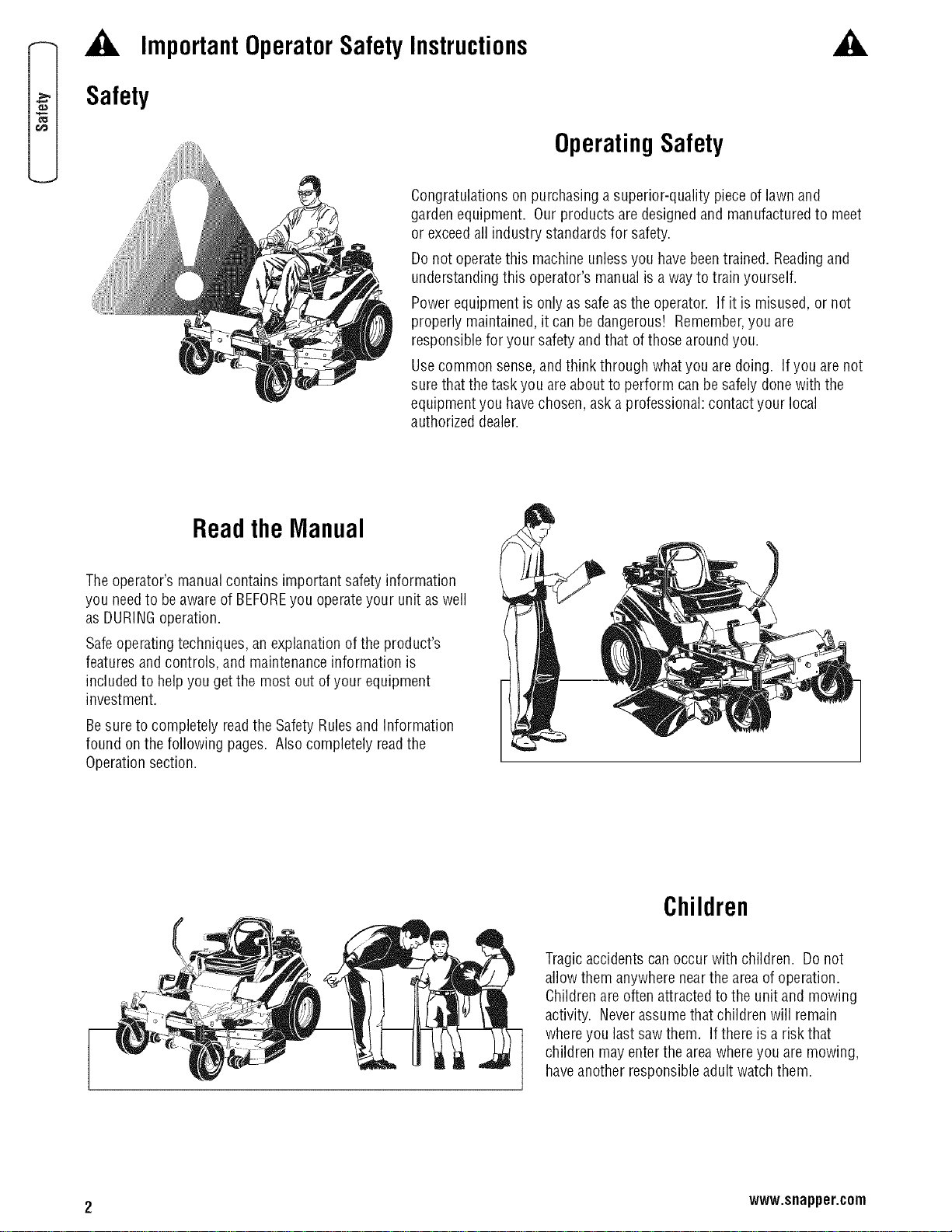
ImportantOperatorSafetyInstructions
Safety
OperatingSafety
Congratulations on purchasing a superior-quality pieceof lawn and
garden equipment. Our products are designedand manufacturedto meet
or exceedall industry standardsfor safety.
Do not operatethis machine unlessyou havebeentrained. Readingand
understanding this operator's manualis awayto train yourself.
Power equipment is only assafe asthe operator. If it is misused, or not
properly maintained,it can be dangerous! Remember,you are
responsible for your safety andthat of those around you.
Usecommon sense,andthink through what you are doing. If you are not
surethat thetask you are about to perform canbe safelydone with the
equipment you havechosen,ask a professional: contact your local
authorized dealer.
ReadtheManual
Theoperator's manualcontains important safety information
you needto beawareof BEFOREyou operateyour unit aswell
as DURINGoperation.
Safeoperatingtechniques, an explanation ofthe product's
featuresand controls, and maintenanceinformation is
includedto help you getthe most out ofyour equipment
investment.
Besure to completely readthe Safety Rulesand information
found on the following pages. Alsocompletely readthe
Operationsection.
Children
Tragicaccidents can occur with children. Donot
allow them anywherenearthe area of operation.
Childrenare often attractedto the unit and mowing
activity. Neverassumethat children will remain
whereyou last saw them. If there is a risk that
children may enterthe areawhereyou are mowing,
haveanother responsible adult watchthem.
2 www.snapper.com
A
ImportantOperatorSafetyInstructions(Continued)
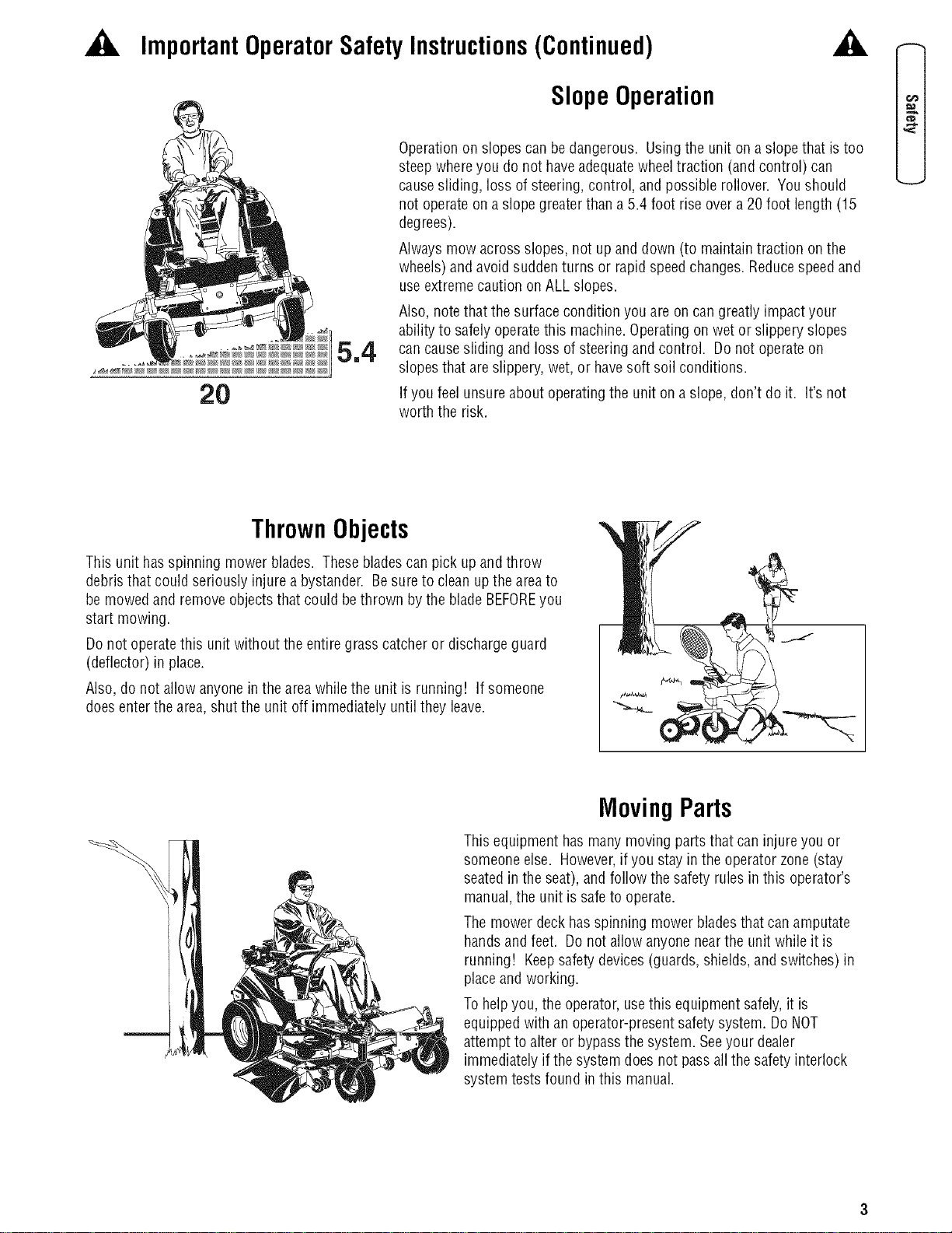
SlopeOperation
A
20
Operationon slopes can be dangerous. Using the unit on a slopethat is too
steep whereyou do not haveadequatewheeltraction (and control) can
causesliding, loss of steering, control, and possible rollover. You should
not operateon a slopegreaterthan a 5.4 foot riseover a 20 foot length (15
degrees).
Always mow across slopes, not up and down (to maintaintraction on the
wheels) and avoid suddenturns or rapid speedchanges.Reducespeedand
useextremecaution on ALL slopes.
Also, notethat the surface condition you are on cangreatly impactyour
ability to safely operatethis machine.Operatingon wet or slippery slopes
can causesliding and loss of steering and control. Donot operateon
slopes that areslippery, wet, or havesoft soil conditions.
If you feel unsureabout operatingthe unit on a slope, don't do it. It's not
worth the risk.
ThrownObjects
This unit hasspinning mower blades. Thesebladescanpick up and throw
debristhat could seriously injure a bystander. Besure to clean upthe areato
be mowed and removeobjectsthat could bethrown bythe blade BEFOREyou
start mowing.
Do not operatethis unit without the entiregrass catcher or dischargeguard
(deflector) in place.
Also, do not allow anyonein the areawhile the unit is running! if someone
doesenterthe area,shut the unit off immediately until they leave.
Moving Parts
This equipment hasmany moving parts that caninjure you or
someoneelse. However,if you stayin the operatorzone (stay
seatedin the seat), and follow the safety rules in this operator's
manual,the unit is safeto operate.
Themower deck hasspinning mower bladesthat can amputate
handsand feet. Donot allow anyonenearthe unit while it is
running! Keepsafetydevices(guards,shields,andswitches) in
placeand working.
Tohelpyou, the operator, usethis equipment safely, it is
equippedwith an operator-presentsafetysystem. Do NOT
attempt to alter or bypassthe system. Seeyour dealer
immediately if the system does not pass all thesafety interlock
systemtests found in this manual.
,_ ImportantOperatorSafety Instructions(Continued) ,_
o_
r#3
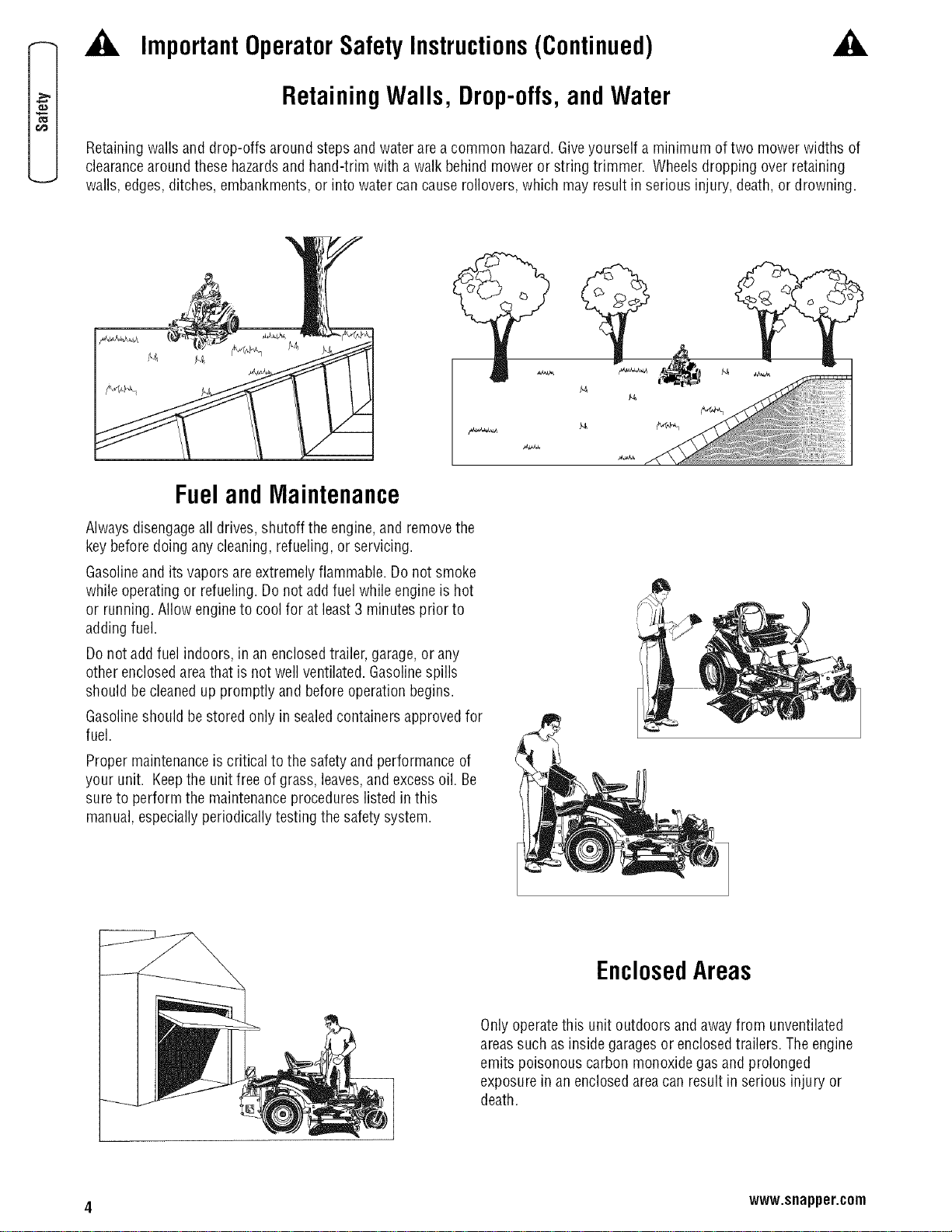
RetainingWalls, Drop-offs,and Water
Retaining walls and drop-offs around steps and water are a common hazard.Giveyourself a minimum of two mower widths of
clearancearoundthese hazardsand hand-trim with a walk behind mower or string trimmer. Wheels dropping over retaining
walls, edges,ditches, embankments, or into water can cause rollovers,which may result in serious injury, death, or drowning.
FuelandMaintenance
Alwaysdisengageall drives, shutoff the engine,and removethe
key beforedoing anycleaning, refueling, or servicing.
Gasolineand its vapors are extremely flammable. Do not smoke
while operating or refueling. Do not addfuel while engineis hot
or running. Allow engine to cool for at least 3 minutesprior to
adding fuel.
Do not add fuel indoors, in an enclosedtrailer, garage,or any
other enclosedareathat is not well ventilated. Gasolinespills
should be cleanedup promptly and before operationbegins.
Gasolineshould be stored only in sealedcontainers approvedfor
fuel.
Proper maintenanceis critical to the safety and performance of
your unit. Keepthe unit freeof grass,leaves,and excess oil. Be
sureto perform the maintenanceprocedures listed in this
manual, especiallyperiodically testing the safety system.
EnclosedAreas
Onlyoperatethis unit outdoors and away from unventilated
areassuch asinside garagesor enclosedtrailers. Theengine
emits poisonous carbon monoxidegas and prolonged
exposurein an enclosedareacan result in serious injury or
death.
4 www.snapper.com
ImportantOperatorSafety Instructions(Continued)
Readthese safety rulesand follow them closely. Failureto obeythese rulescould result in loss of control of unit,
severepersonal injury or deathto you, or bystanders,or damageto property or equipment.
Thismowinqdeckis capableof amputatinqhandsandfeet andthrowinqobjects. Thetriangle _ in text signifies
important cautions or warnings which must befollowed.
GENERALOPERATION
1. Read,understand,and follow all instructions in the
manualand on the unit beforestarting.
2. Donot put handsor feet near rotating parts or under the
machine. Keepclear of the dischargeopening at all
times.
3. Onlyallow responsible adults,who arefamiliar with the
instructions, to operatethe unit (local regulations can
restrict operatorage).
4. Clearthearea of objects such as rocks, toys, wire, etc.,
which could be picked up andthrown by the blade(s).
5. Besurethe area is clearof other peoplebefore mowing.
Stopthe unit if anyoneentersthe area.
6. Nevercarry passengers.
7. Donot mow in reverse unlessabsolutely necessary.
Always look down and behind before and whiletravelling
in reverse.
8. Neverdirect discharge materialtoward anyone. Avoid
discharging material against a wall or obstruction.
Materia/may ricochetback toward the operator. Stopthe
blade(s)when crossing gravelsurfaces.
9. Donot operatethe machine without the entire grass
catcher, dischargeguard (deflector), or othersafety
devicesin placeand operational.
10. Slow down beforeturning.
11. Neverleavea running unit unattended.Always disengage
the blades (PTO),set parking brake,stop engine,and
remove keysbeforedismounting.
12. Disengageblades(PTO)when not mowing. Shut off
engine and wait for all parts to come to a completestop
beforecleaningthe machine, removing the grass catcher,
or uncloggingthe discharge guard.
13. Operatethe machineonly in daylight or good artificial
light.
14. Donot operatethe unit while underthe influence of
alcohol or drugs.
15 Watch for traffic whenoperating near or crossing
roadways.
16. Useextra carewhen loading or unloading the unit into a
trailer or truck.
17. Always weareyeprotection when operatingthis unit.
18. Dataindicatesthat operators,age 60 years and above,
are involved in a large percentageof power equipment-
relatedinjuries. Theseoperators should evaluatetheir
ability to operatethe equipment safelyenough to protect
themselvesand others from injury.
19. Followthe manufacturer'srecommendationsfor wheel
weights or counterweights.
20. Keepin mind the operatoris responsiblefor accidents
occurring to other people or property.
21. All drivers should seekand obtain professionaland
practicalinstruction.
22. Always wearsubstantial footwear and trousers. Never
operatewhen barefoot or wearingsandals.
23. Beforeusing, alwaysvisually checkthat the bladesand
bladehardwareare present,intact, and secure. Replace
worn or damagedparts.
24. Disengageattachments before: refueling, removing an
attachment, makingadjustments (unlessthe adjustment
can be madefrom the operator's position).
25. Whenthe machineis parked,stored, or left unattended,
lowerthe cutting meansunlessa positive mechanical
lock is used.
26. Beforeleavingthe operator's positionfor any reason,
engagethe parking brake(if equipped),disengagethe
blades(PTO),stop the engine,andremove the key.
27. To reducefire hazard,keepthe unit freeof grass,leaves,
& excess oil. Do not stop or park over dry leaves,grass,
or combustible materials.
28. It isa violation of California Public ResourceCode
Section4442 to use or operatethe engine on or nearany
forest-covered, brush-covered, or grass-covered land
unlessthe exhaustsystem is equippedwith a spark
arrester meeting anyapplicablelocal or state laws. Other
states or federalareasmay havesimilar laws.
29. OSHAregulations may require the useof hearing
protection whenexposedto sound levelsgreaterthan 85
dBAfor an 8 hour time period.
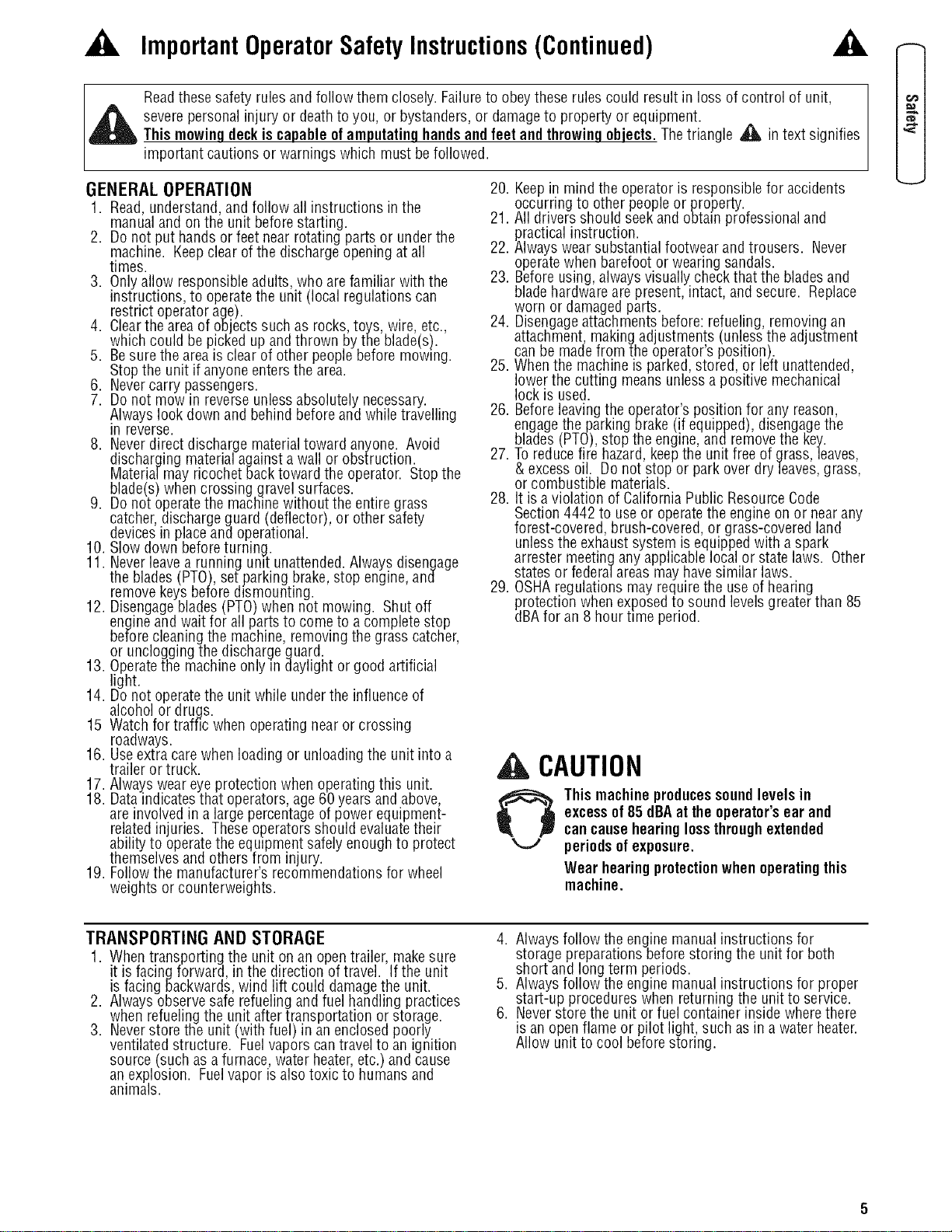
A CAUTION
O his machineproducessoundlevels in
excessof85 dBAat the operator'sear and
cancausehearinglossthroughextended
periodsofexposure.
Wear hearingprotectionwhen operatingthis
machine.
TRANSPORTING AND STORAGE
1. Whentransporting the unit on an open trailer, makesure
it is facing forward, in the direction oftravel. If the unit
is facing backwards,wind lift could damagethe unit.
2. Always observesafe refuelingand fuel handling practices
when refuelingthe unit after transportation or storage.
3. Neverstore the unit (with fuel) in an enclosedpoorly
ventilated structure. Fuelvapors can travelto an ignition
source (such asa furnace, water heater,etc.)and cause
an explosion. Fuelvapor is alsotoxic to humans and
animals.
4. Always follow the engine manualinstructions for
storage preparationsbefore storing the unit for both
short and long term periods.
5. Always follow the engine manualinstructions for proper
start-up procedures when returning the unit to service.
6. Neverstore the unit or fuel container inside wherethere
isan openflame or pilot light, such asin a water heater.
Allow unit to cool beforestoring.
ImportantOperatorSafety Instructions(Continued)
o_
r#3
SLOPE OPERATION
Slopesarea majorfactor relatedto loss-of-controlandtip-over
accidents,which can resultin severeinjury or death.Operation
on all slopesrequiresextracaution.If youcannot backupthe
slopeor if youfeeluneasyon it, do not operateon it.
Controlof awalk-behindor ride-onmachinesliding on a slope
will not be regainedbythe applicationof thebrake. Themain
reasonsfor lossof control are:insufficienttire grip on the
ground,speedtoo fast,inadequatebraking,thetypeof
machineis unsuitablefor its task,lack ofawarenessofthe
groundconditions, incorrecthitching andload distribution.
1. Mow across slopes, not up and down.
2. Watch for holes, ruts, or bumps. Uneventerrain could
overturn the unit. Tallgrass canhide obstacles.
3. Choosea slow speedsothat you will not haveto stop or
changespeedswhile on the slope.
4. Donot mow on wet grass. Tires may loosetraction.
5. Avoid starting, stopping, or turning on a slope. Iftires
losetraction (i.e. machine stops forward motion on a
slope), disengagethe blade(s) (PTO)and driveslow off
the slope.
6. Keepall movement on slopes slow and gradual. Donot
makesuddenchanges in speedor direction, which could
causethe machineto rollover.
7. Useextra carewhile operating machineswith grass
catchers or other attachments;they can affect the
stability of the unit. Do not useon steepsslopes.
B. Donot try to stabilizethe machine by putting your foot
onthe ground (ride-on units).
9. Donot mow near drop-offs, ditches, or embankments.
The mower could suddenly turn over if a wheel isover
the edge of a cliff or ditch, or if an edgecavesin.
10. Donot usegrass catchers on steepslopes.
11. Donot mow slopes ifyou cannot back up them.
12. Seeyour authorized dealer/retailerfor recommendations
ofwheel weights or counterweights to improve stability.
13. Removeobstacles such as rocks, tree limbs, etc.
14. Useslow speed.Tires may losetraction on slopes even
though the brakesarefunctioning properly.
15. Donot turn on slopes unless necessary,and then, turn
slowly and gradually uphill, if possible. Never mow
down slopes.
TOWED EQUIPMENT (RIDE-ON UNITS)
1. Tow only with a machinethat hasa hitch designedfor
towing. Donot attachtowed equipmentexceptat the
hitch point.
2. Followthe manufacturer'srecommendationsfor weight
limit for towed equipment and towing on slopes. See
attaching a trailer under OPERATION.
AWARNING
Never operate on slopesgreaterthan150whichis a
rise of 5.4 feet (1,6 m) vertically in20 feet (6 m)
horizontally.
Selectslow groundspeedbeforedrivingontoslope.
Useextracaution when operating on slopeswith rear-
mountedgrasscatchers.
Mow acrosstheface of slopes, notup anddown,use
cautionwhen changingdirectionsandDONOTSTART
ORSTOPONSLOPE.
3. Neverallow children or others in or on towed equipment.
4. Onslopes,the weight of thetowed equipment maycause
loss of traction and loss of control.
5. Travelslowly and allow extra distanceto stop.
6. Donot shift to neutral and coast down hill.
CHILDREN
Tragicaccidentscanoccur ifthe operatorisnot alertto the
presenceofchildren. Childrenare oftenattractedto the unit
andthe mowingactivity. Neverassumethat childrenwill
remainwhereyou lastsawthem.
1. Keepchildren out ofthe mowing areaand under the
watchful care of anotherresponsible adult.
2. Bealert andturn unit off if children enterthe area.
3. Beforeand during reverseoperation, look behind and
downfor small children.
4. Nevercarry children, evenwith the blade(s) off. They
may fall off and beseriously injured or interfere with safe
unit operation. Childrenwho havebeengiven rides in
the past maysuddenly appear in the mowing areafor
another ride and be run over or backedover bythe
machine.
5. Neverallow childrento operatethe unit.
6. Useextra carewhenapproaching blind corners, shrubs,
trees, or other objectsthat may obscure vision.
EMISSIONS
1. Engineexhaustfrom this product contains chemicals
known, in certain quantities,to causecancer,birth
defects,or other reproductive harm.
2. Lookfor the relevant Emissions Durability Period andAir
Index information on the engineemissions label.
IGNITION SYSTEM
1. This spark ignition system complies with CanadianICES-
002.
6 www.snapper.com

ImportantOperatorSafety Instructions(Continued) ---
SERVICE AND MAINTENANCE
Safe HandlingofGasoline
1. Extinguishall cigarettes, cigars, pipes, and other sources
of ignition.
2. Useonly approvedgasolinecontainers.
3. Neverremovethe gascap or add fuel with the engine
running. Allow the engineto cool before refueling.
4. Neverfuel the machineindoors.
5. Neverstore the machine or fuelcontainer where there is
an open flame, spark, or pilot light such as neara water
heateror other appliance.
6. Neverfill containers inside a vehicle or on atruck bed
with a plastic bed liner. Always placecontainerson the
ground away from your vehicle beforefilling.
7. Removegas-poweredequipment from the truck or trailer
and refuelit on the ground. If this is not possible,then
refuelsuch equipment on a trailer with a portable
container, ratherthan from a gasoline dispensernozzle.
8. Keepnozzlein contact with the rim of the fueltank or
container opening atall times until fueling is complete.
Donot usea nozzlelock-open device.
9. If fuel isspilled on clothing, changeclothing immediately.
10. Neverover-fill the fuel tank. Replacegascap andtighten
securely.
11. Useextra carein handling gasolineand other fuels. They
are flammable and vapors areexplosive.
12. If fuel isspilled, do not attempt to start the enginebut
movethe machineawayfrom the areaof spillageand
avoid creating anysource of ignition until fuel vapors
havedissipated.
13. Replaceall fuel tank caps and fuel container caps
securely.
Service& Maintenance
1. Neverrun the unit in an enclosed areawherecarbon
monoxide fumes may collect.
2. Keepnuts and bolts, especiallyblade attachmentbolts,
tight and keepequipment in good condition.
3. Nevertamper with safety devices.Checktheir proper
operation regularlyand makenecessaryrepairs ifthey
are not functioning properly.
4. Keepunit freeof grass, leaves,or other debris build-up.
Cleanup oil or fuel spillage, and removeany fuel-soaked
debris. Allow machineto cool beforestorage.
5. If you strike an object,stop and inspectthe machine.
Repair,if necessary,before restarting.
6. Nevermakeadjustments or repairs with the engine
running.
7. Checkgrass catchercomponents and the discharge
guard frequently and replacewith manufacturer's
recommendedparts,when necessary.
8. Mower bladesare sharp. Wrap the blade or weargloves,
and useextra caution whenservicing them.
9. Checkbrakeoperationfrequently. Adjust andservice as
required.
10. Maintain or replacesafety and instructions labels,as
necessary.
11. Donot removethe fuel filter whenthe engine is hot as
spilled gasoline may ignite. Do not spreadfuel line
clamps further than necessary. Ensureclamps grip
hosesfirmly overthe filter after installation.
12. Donot usegasolinecontaining METHANOL,gasohol
containing more than 10% ETHANOL,gasoline additives,
or white gasbecauseengine/fuel system damagecould
result.
13. If the fuel tank must be drained,it should be drained
outdoors.
14. Replacefaulty silencers/mufflers.
15. Maintain or replacesafety and instruction labelsas
necessary.
16. Useonly factory authorized replacementparts when
making repairs.
17. Always comply with factory specifications on all settings
and adjustments.
18. Onlyauthorizedservice locations should be utilized for
majorservice and repair requirements.
19. Neverattempt to make major repairson this unit unless
you havebeen properlytrained. Improper service
procedurescan result in hazardousoperation, equipment
damageand voiding of manufacturer'swarranty.
20. On multiple blade mowers, take careas rotating one
bladecancause other bladesto rotate.
21. Donot changeengine governor settings or over-speed
the engine. Operatingthe engine atexcessivespeedcan
increasethe hazardof personal injury.
22. Disengagedrive attachments,stop the engine,remove
the key,and disconnect the spark plug wire(s) before:
clearing attachmentblockagesand chutes, performing
service work, striking an object, or if the unit vibrates
abnormally. After striking an object, inspectthe machine
for damageand make repairsbefore restartingand
operatingthe equipment.
23. Neverplacehandsnearthe moving parts,such asa
hydro pump cooling fan, when thetractor is running.
(Hydro pump cooling fans aretypically located on top of
the transaxle).
24. Unitswith hydraulic pumps, hoses,or motors:
WARNING:Hydraulicfluid escaping under pressure may
havesufficient force to penetrateskin and causeserious
injury. If foreign fluid is injected into the skin it must be
surgically removedwithin a few hours bya doctor
familiar with this form of injury or gangrene may result.
Keepbodyand handsaway from pin holes or nozzles
that eject hydraulic fluid under high pressure. Usepaper
or cardboard, and not hands,to search for leaks. Make
sure all hydraulic fluid connections aretight and all
hydraulic hoses and linesare in good condition before
applying pressure to the system, if leaks occur,havethe
unit servicedimmediately byyour authorized dealer.
25. WARNING:Stored energydevice. Improper releaseof
springs can result in serious personalinjury. Springs
should be removedby an authorized technician.
26. Models equippedwith an engine radiator:WARNING:
Storedenergydevice. Topreventserious bodily injury
from hot coolant or steam blow-out, neverattempt to
removethe radiatorcapwhile the engine is running.
Stopthe engineand wait until it is cool. Eventhen, use
extremecare when removingthe cap.
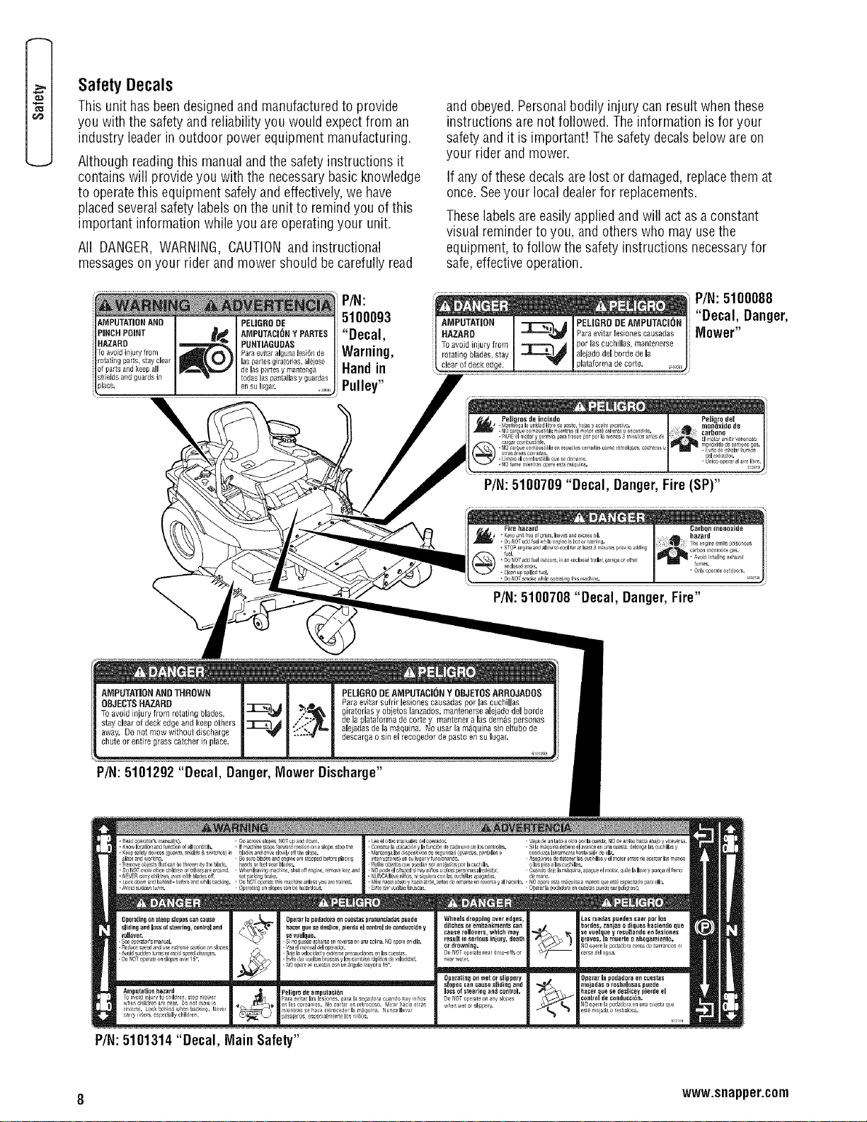
SafetyDecals
This unit hasbeendesignedand manufacturedto provide
you with thesafety and reliability you would expectfrom an
industry leaderin outdoor powerequipment manufacturing•
Although readingthis manualand the safety instructions it
contains will provideyou with the necessarybasic knowledge
to operatethis equipment safelyand effectively,we have
placedseveralsafety labels onthe unit to remindyou of this
important information while you are operatingyour unit.
All DANGER,WARNING, CAUTIONand instructional
messageson your rider and mower should be carefully read
P/N:
AMPUTATION AND PELIGRO DE
PINCH POINT AMPUTACION Y PARTE$ "Decal,
HAZARD PUNTiAGUUA$
Paleevit_raigunalesidnde Warning,
rotatingparts, stayclear losparsesDilatories,al_iese
ofpartsandkeep all delospartesy manterlga Handin
shieldsandguardsin redeslospantaliasy guardas
pl......... lugar. Pulley"
and obeyed•Personalbodily injury can result when these
instructions are not followed. Theinformation is for your
safetyand it is important! Thesafety decals beloware on
your rider and mower•
If any ofthese decals are lost or damaged, replacethem at
once. Seeyour local dealerfor replacements.
Theselabelsare easilyapplied and will act asa constant
visual reminder to you, and others who may usethe
equipment,to follow the safety instructions necessaryfor
safe,effectiveoperation.
AMPUTATION PELJGRODEAMPUTACION
HAZARD _r_ Paraevitarlesionescausadas
Toavoidinjuryfrom _----_,d parloscuchilles,mantenerse
rotatingblades,stay _ alejadodelbordedeJa
clearofdeckedge.
P/N:5100088
"Decal, Danger,
Mower"
P/N:5100709 "Decal, Danger,Fire (SP)"
P/N: 5100708 "Decal, Danger,Fire"
AMPUTATION AND THROWN
OBJECTS HAZARD
To avoid in}ury from rotating blades,
stay clear of deck edge and keep others
away• Do not mow without discharge
chute or entire grass catcher in place.
PELIGRODEAMPUTACIONY OBJETOSARROJADOS
Pare evitar sufrir lesionee causadas per Jas euchillas
giratodas y obietos lanzados, mantenerse ale ado del borde
de la glataforma de corte y manteoer a los demos personas
ale adas de la m_quina. No user la m_quina sin eJtubo de
descarga o sin e recogedor de paste en su ugar.
m m
P/N: 5101292 "Decal, Danger,MowerDischarge"
8 www.snapper.com
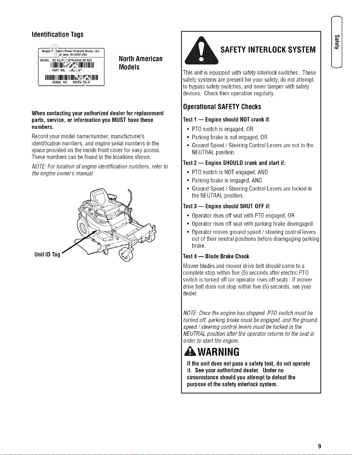
IdentificationTags
_\%_,dkee, WJ 53261 USA
,iMm,i . m,l,mm
SER,.L.o. xx×x_
NorthAmerican
Models
Whencontactingyourauthorizeddealer forreplacement
parts,service, or informationyouMUST havethese
numbers.
Recordyour model name/number, manufacturer's
identification numbers, and engineserial numbers in the
spaceprovided on the inside front cover for easyaccess.
Thesenumbers can befound in the locations shown.
NOTE."For locationof engineidentification numbers, refer to
theengine owner's manual
UnitID Tag
SAFETYINTERLOCKSYSTEM
This unit is equippedwith safety interlock switches. These
safety systems are presentfor your safety,do not attempt
to bypasssafety switches, and nevertamper with safety
devices. Checktheir operation regularly.
Operational SAFETYChecks
Test1 -- EngineshouldNOTcrank if:
• PTOswitch is engaged,OR
• Parkingbrakeis not engaged,OR
• Ground Speed/ SteeringControl Leversare not in the
NEUTRALposition.
Test2 -- EngineSHOULDcrankandstartif:
• PTOswitch is NOTengaged,AND
• Parkingbrakeis engaged,AND
• Ground Speed/ SteeringControl Leversare locked in
the NEUTRALposition.
Test3 -- EngineshouldSHUTOFFif:
• Operatorrises off seatwith PTOengaged,OR
• Operatorrises off seatwith parking brakedisengaged.
• Operatormovesground speed/steering control levers
out of their neutral positions beforedisengagingparking
brake.
Test4 -- BladeBrakeCheck
Mower bladesand mower drivebelt should come to a
completestop within five (5) secondsafter electric PTO
switch is turned off (or operator rises off seat). If mower
drive belt doesnot stop within five (5) seconds, seeyour
dealer.
NOTE."Oncethe enginehas stopped,PTOswitch must be
turned off, parking brakemust be engaged,and theground
speed/steering control levers must be locked in the
NEUTRALposition after theoperator returns to theseat in
order to start theengine.
WARNING
If the unitdoesnotpassa safetytest, do notoperate
it. See yourauthorizeddealer. Underno
circumstance shouldyouattemptto defeatthe
purposeofthe safetyinterlocksystem.
e=
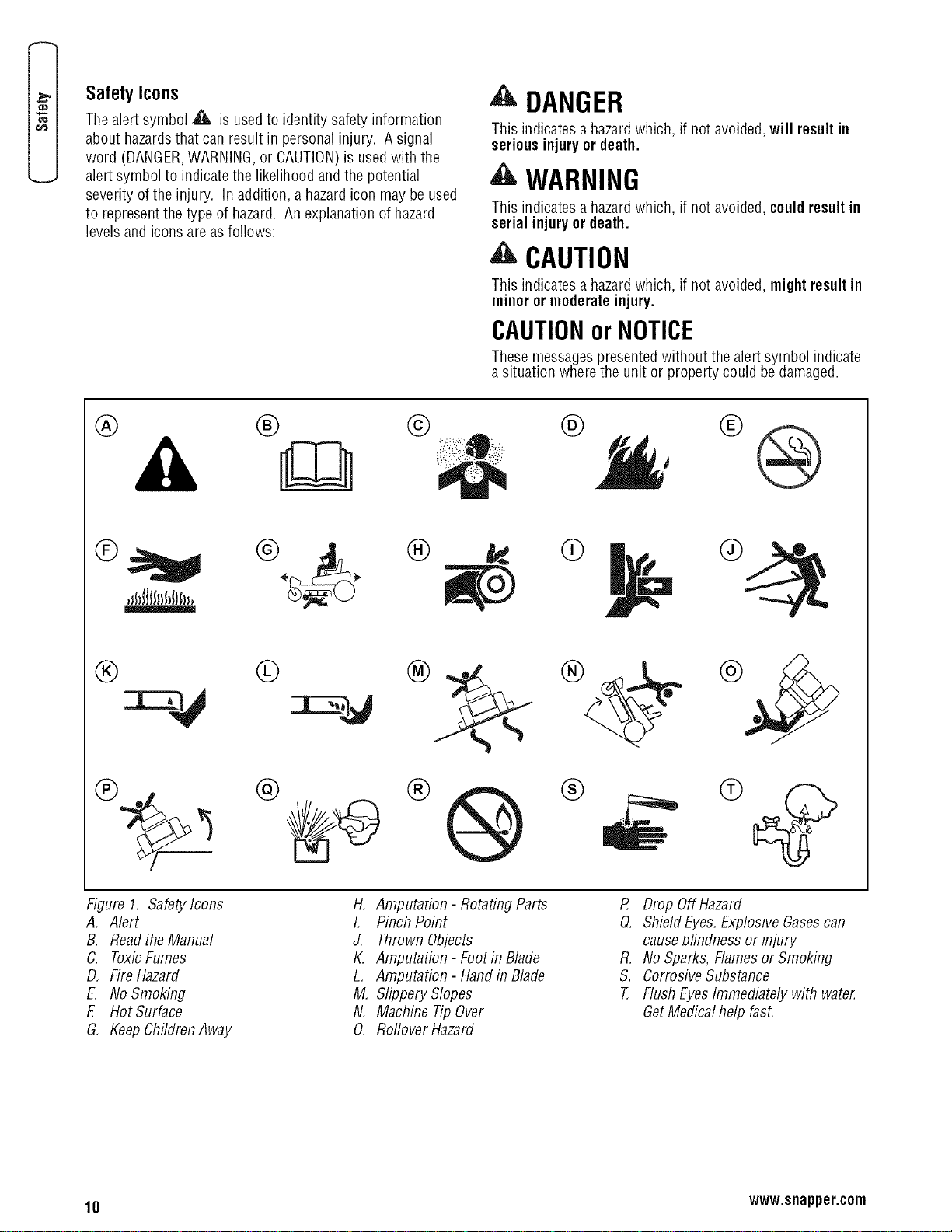
SafetyIcons
Thealertsymbol A is usedto identity safety information
about hazardsthat can result in personal injury. A signal
word (DANGER,WARNING,or CAUTION)is usedwith the
alertsymbol to indicate the likelihood and the potential
severity of the injury. Inaddition, a hazardicon may be used
to representthe type of hazard. An explanationof hazard
levels and icons are asfollows:
DANGER
This indicatesa hazardwhich, if not avoided,will result in
seriousinjuryor death.
'_ WARNING
This indicatesa hazardwhich, if not avoided, couldresultin
serial injuryor death.
,i_ CAUTION
This indicatesa hazardwhich, if not avoided, mightresultin
minor ormoderateinjury.
CAUTIONor NOTICE
Thesemessagespresentedwithout the alertsymbol indicate
a situation wherethe unit or property could be damaged.
® ® ©
® @ OD
® ®
®
,Jl_JllfJlJ_lls_J,
@ © ® ® ®
Figure 1. SafetyIcons
A, Alert
B. ReadtheManual
C. ToxicFumes
D, FireHazard
E. No Smoking
E Hot Surface
G, Keep ChildrenAway
@ ®
H. Amputation - RotatingParts
L PinchPoint
J. Thrown Objects
K. Amputation - Footin Blade
L, Amputation - Handin Blade
M. Slippery Slopes
N. Machine TipOver
O. RofloverHazard
P, Drop OffHazard
Q. Shield Eyes.ExplosiveGasescan
causeblindness or injury
R, No Sparks,Flamesor Smoking
S. CorrosiveSubstance
T, FlushEyes Immediately with water.
GetMedical help fast.
10 www.snapper.com
Assembly
Readand followthe assemblyandadjustment
instructionsforyourmower.
All fasteners arein thepartsbag. Do notdiscard
anypartsor material untilthe unitis assembled.
NOTE:Inthis instruction book, left and right describethe
location of a part with the operator onthe seat.
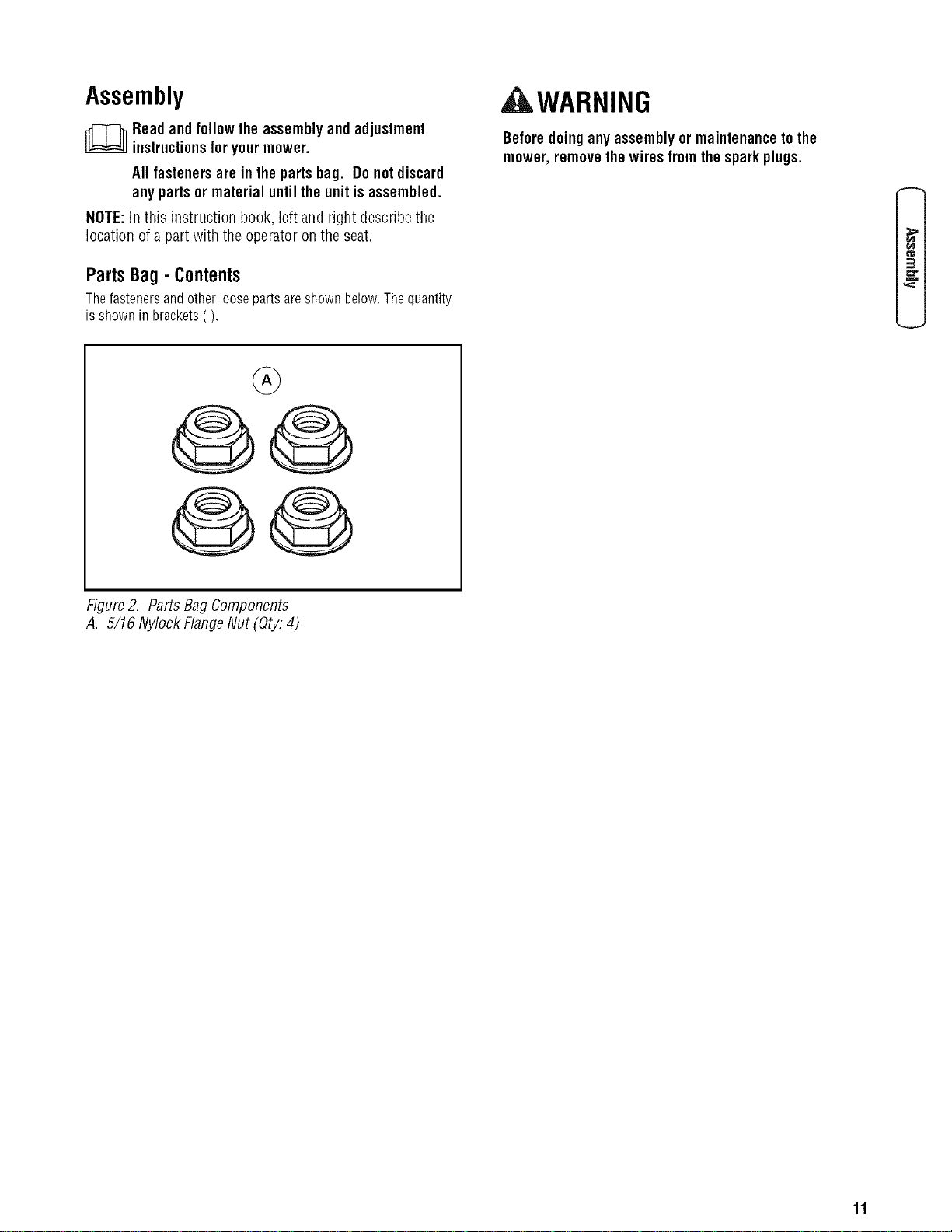
PartsBag- Contents
Thefastenersandotherloosepartsareshownbelow.Thequantity
isshownin brackets().
AWARNING
Beforedoinganyassemblyor maintenancetothe
mower,removethewires fromthespark plugs.
3
@0
@0
Figure2. Parts Bag Components
A. 5/16 Nylock FlangeNut (Qty."4)
11
E
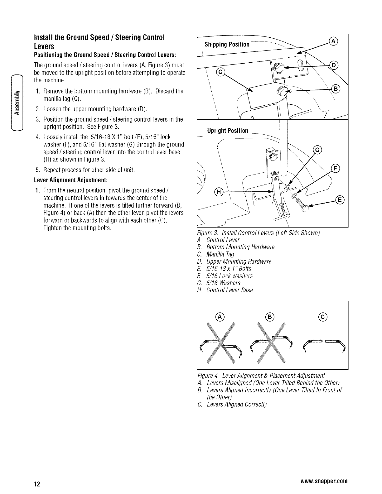
Installthe GroundSpeed/ SteeringControl
Levers
Positioningthe GroundSpeed/ SteeringControlLevers:
Theground speed/steering control levers (A,Figure3) must
be moved to the upright position beforeattempting to operate
the machine.
1. Removethe bottom mounting hardware (B). Discardthe
manillatag (C).
2. Loosenthe upper mounting hardware (D).
3. Position the ground speed/ steering control levers in the
upright position. See Figure3.
4. Loosely install the 5/16-18 X 1" bolt (E),5/16" lock
washer (F),and 5/16" flat washer(G)through the ground
speed/ steering control leverinto the control leverbase
(H)as shown in Figure3.
5. Repeatprocess for other side of unit.
LeverAlignmentAdjustment:
1. Fromthe neutral position, pivot the ground speed/
steering control levers in towards the center of the
machine. If one of the levers is tilted further forward (B,
Figure4) or back (A) then the other lever,pivot the levers
forward or backwardsto align with eachother (C).
Tighten the mounting bolts.
ShippingPosition.......... __../_
Figure3, Instafl Control Levers (Left Side Shown)
A. Control Lever
B, Bottom Mounting Hardware
C. Manilla Tag
D. UpperMounting Hardware
E. 5/16-18x 1"Bolts
F, 5/16 Lock washers
G. 5/16 Washers
H. Control LeverBase
® ® ©
Figure4, LeverAlignment & PlacementAdjustment
A, LeversMisaligned (OneLever TiltedBehind theOther)
B, LeversAlignedIncorrectly (OneLever TiltedIn Front of
theOther)
C. LeversAligned Correctly
12 www.snapper.com
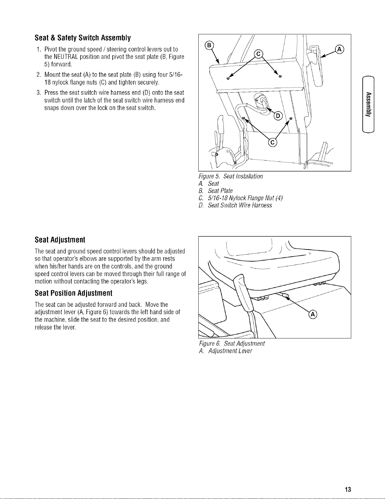
Seat& SafetySwitchAssembly
1. Pivot theground speed/ steering control levers out to
the NEUTRALposition and pivot the seat plate (B,Figure
5) forward.
2. Mount the seat (A) to the seat plate (B) usingfour 5/16-
18 nylock flangenuts (C)andtighten securely.
3. Pressthe seatswitch wire harnessend (D) ontothe seat
switch until the latch of the seat switch wire harness end
snaps down over the lock on the seatswitch.
¢'D
3
Figure5. SeatInstallation
A, Seat
B. SeatPlate
C. 5/16-18 Nylock FlangeNut (4)
D, SeatSwitch WireHarness
SeatAdjustment
Theseatand ground speedcontrol levers should be adjusted
sothat operator's elbowsaresupported bythe arm rests
when his/her hands are onthe controls, and the ground
speedcontrol levers canbe movedthrough their full range of
motion without contacting the operator's legs.
Seat Position Adjustment
Theseatcan be adjustedforward and back. Movethe
adjustment lever (A, Figure6) towards the left hand side of
the machine,slidethe seat to the desired position, and
releasethe lever.
Figure6. SeatAdjustment
A. Adjustment Lever
13
E
r_
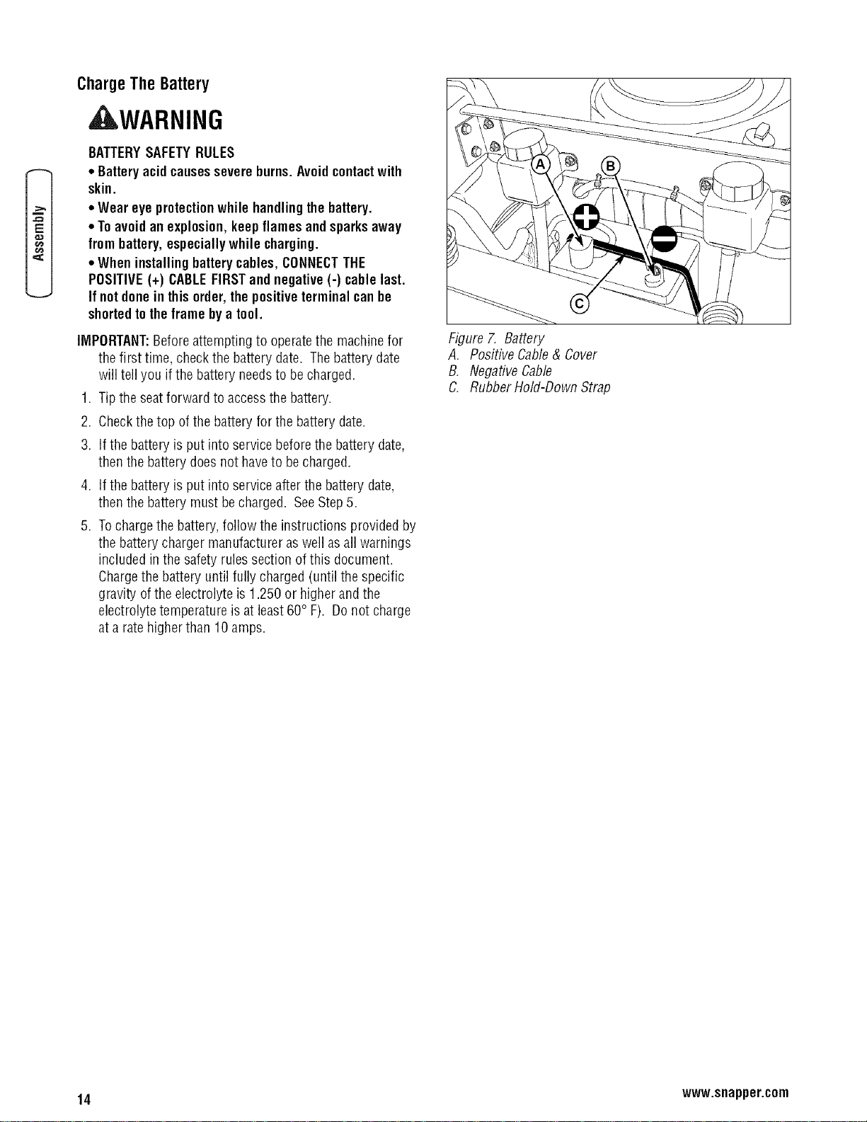
ChargeThe Battery
,d WARNING
BATTERYSAFETYRULES
• Batteryacidcausessevereburns.Avoidcontactwith
skin.
• Wear eye protectionwhile handlingthe battery.
• Toavoidan explosion,keepflamesandsparksaway
from battery,especiallywhile charging.
• Wheninstallingbatterycables, CONNECTTHE
POSITIVE(+) CABLEFIRSTand negative(-) cable last.
If not donein this order,the positiveterminal canbe
shortedtotheframe by a tool.
IMPORTANT:Beforeattempting to operatethe machinefor
the first time, checkthe batterydate. Thebattery date
will tell you if the battery needsto becharged.
1. Tip the seatforward to access the battery.
2. Checkthe top of the battery for the battery date.
3. If the battery is put into servicebefore the battery date,
then the battery doesnot haveto becharged.
4. If the battery is put into serviceafter the battery date,
then the battery must be charged. SeeStep5.
5. Tochargethe battery, follow the instructions provided by
the battery charger manufacturer aswell asall warnings
included in the safety rulessection of this document.
Chargethe battery until fully charged (until the specific
gravity ofthe electrolyte is 1.250 or higher and the
electrolyte temperature is at least60° F). Donot charge
at a rate higher than 10 amps.
Figure 7. Battery
A, Positive Cable& Cover
B, NegativeCable
C. Rubber Hold-Down Strap
14 www.snapper.com
Howto Preparethe Engine
NOTE:Theengine was shipped from thefactory filled with
oil. Checkthe levelof the oil. Add oil as needed.
NOTE:Theoperation of a new enginewill sometimes result
in a slight amount of smoke. This smoke is causedby paint
or oil on or around the muffler. This is normal and only
expectedduring initial operation.
A separateengine manualis also includedwith the unit. See
this engine manualfor the manufacturer's instructions for
thetype of oil and gasolineto use. Beforeyou usethe unit,
readthe information on safety,operation, maintenanceand
storage.
, WARNING
Followtheenginemanufacturer'sinstructionsfor the
typeof gasolineand oil to use. Alwaysusea safety
gasolinecontainer. Donotsmokewhen adding
gasolineto theengine. When insideandenclosure,do
notfill with gasoline. Beforeyouadd gasoline,stop
the engine. Lettheenginecool for several minutes.
IMPORTANT:This unit isequipped with an internal
combustion engine and must not be usedon or near any
unimproved forest-covered, brush-covered or grass-covered
land unless the engine'sexhaustsystem is equipped with a
spark arrestor meeting applicablelocalor state laws(if any).
If a spark arrestor is used, it must be maintained in effective
working order bythe operator.
In the stateof Californiathe aboveis required by law
(Section 4442 ofthe California Public ResourcesCode).
Otherstates may havesimilar laws. Federallaws apply
federallands.
In some areas, locallaws requiresthe useof a resistor spark
plug to control the ignition signals. Seean Authorized
ServiceCenterfor a resistor spark plug for the engine.
NOTE:Actual sustained horsepower will likely be lower due
to operating limitations and environmental factors.
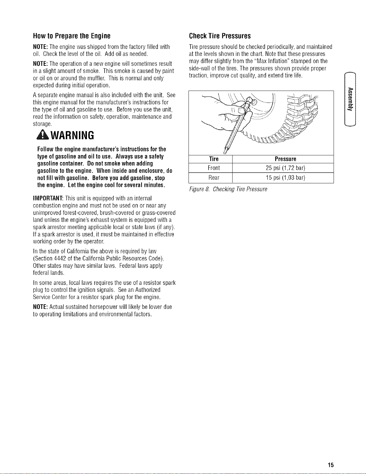
CheckTire Pressures
Tirepressure should becheckedperiodically,and maintained
atthe levels shown in the chart. Notethat these pressures
may differ slightly from the "Max Inflation"stampedon the
side-wall of the tires. The pressuresshown provide proper
traction, improve cut quality, and extendtire life.
Tire Pressure
Front 25 psi (1,72 bar)
Rear 15 psi (1,03 bar)
Figure8, CheckingTirePressure
¢"D
3
15
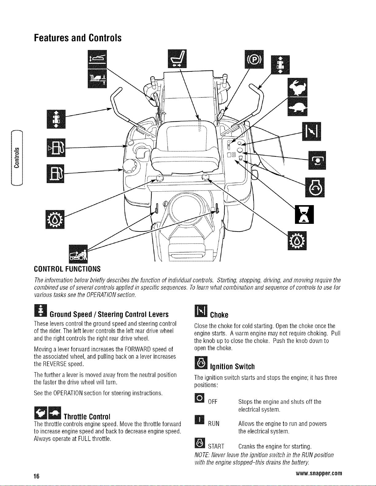
FeaturesandControls
=n
z=,=
CONTROLFUNCTIONS
Theinformation below briefly describesthe function of individual controls, Starting, stopping, driving, and mowing require the
combined useof several controls applied in specific sequences. Tolearn what combination and sequenceof controls to usefor
various tasks seethe OPERATIONsection,
GroundSpeed/ SteeringControlLevers
Theseleverscontrol the ground speedand steering control
of the rider.The left levercontrols the left rear drive wheel
and the right controls the right rear drive wheel.
Moving a leverforward increasesthe FORWARDspeedof
theassociated wheel,and pulling back on a leverincreases
the REVERSEspeed.
Thefurther a leveris movedaway from the neutral position
thefaster the drive wheelwill turn.
Seethe OPERATIONsectionfor steering instructions.
Throttle Control
Thethrottle controls engine speed. Movethe throttle forward
to increaseengine speedand backto decreaseengine speed.
Alwaysoperateat FULLthrottle.
Choke
Closethe choke for cold starting. Openthe choke oncethe
engine starts. A warm engine may not require choking. Pull
the knob up to close the choke. Pushthe knob down to
openthe choke.
Ignition Switch
Theignition switch starts and stops the engine; it hasthree
positions:
OFF
H RUN
Stops the engineand shuts off the
electricalsystem.
Allows the engineto run and powers
the electrical system.
[_J START Cranksthe engine for starting.
NOTE."Neverleavethe ignition switch in the RUNposition
with theengine stopped-this drains thebatted4
16 www.snapper.com
B HourMeter
Thehour meter measuresthe number of hours the key has
beenin the RUNposition.
Note: Thehour meter will register thepassage of time when
thekey is in the RUNposition, evenif the engine is not
running. Thehour meterhas aselfcontainedpower source
so the total hours arealways visible.
_PTO Switch
ThePTO(Blade Engage)switch engages(turns the blades
on) and disengages(turns the bladesoff) the mower deck.
Toengagethe PTO,pull UPon the switch. Push DOWNto
disengage.Notethat the operator must be seatedfirmly in
the rider seat for the PTOto function.
Transmission Oil Fill
Transmissionoil is addedthrough thetransmission oil
reservoirs. It also servesasextra holding capacity for oil as
thetransmissions heatup and the oil expands. SeeCHECK
TRANSMISSIONOIL LEVELfor oil level checkand fill
procedures.
TransmissionReleaseLevers
Thetransmission releaselevers deactivatethe transmissions
sothat the unit can be pushedby hand. SeePUSHINGTHE
UNIT BYHANDfor operationalinformation.
SeatAdjustmentLever
Theseatcan be adjustedforward and backward. Move the
adjustment levertowards the left, slidethe seat to the
desiredposition, and releasethe lever.
FuelTank
FuelLevelGauge
Toremovethe cap, turn counterclockwise. Thefuel gauge is
mounted in the fueltank and indicatesthe amount of fuel in
the tank.
Mower Height of Cut Adjustment
Toadjust cutting height, pull the large leverback fully to lock
the control in the attachment raisedtransport position.
Position the cutting height selector pin on the appropriate
hole to achievethe desiredcutting height. Pull backon the
small lift latch leverand large leversimultaneously, and
lower the mower into cutting position.
Forattachmenttransport lift, pull the large lift lever backfully
to lock the control in the attachment raisedtransport
position.
ParkingBrake
DISENGAGE
ENGAGE
Releasesthe parking brake.
Locksthe parking brake.
Pull the parking brakelever backto engagethe parking
brake. Move the leverfully forward to disengagethe parking
brake. NOTE."Tostart the unit theparking brakemust be
engaged.
o
t_
m
17
o
Operation
GeneralOperatingSafety
Beforefirst time operation:
• Besureto read all information in the Safetyand
Operationsections beforeattempting to operatethis
tractor and mower.
• Becomefamiliar with all of the controls and howto stop
the unit.
• Drive in an open areawithout mowing to become
accustomedto the unit brake leveror set the parking
brake.
_WARNING
Never operate on slopesgreaterthan(15°) whichisa
rise of 5.4 feet (1,6 m) verticallyin 20 feet (6 m)
horizontally.
Selectslow groundspeedbeforedrivingontoa slope.
Useextracautionwhen operatingonslopeswith a
rear-mountedgrasscatcher.
Mow acrosstheface ofslopes, notup and down,use
cautionwhen changingdirectionsandDONOTSTART
ORSTOPONSLOPE.
A WARNING
Never allow passengersto rideon theunit.
Beforeleaving theoperator'spositionforany reason,
engagetheparkingbrake, disengagethe PTO,stopthe
engine andremovethekey.
Toreducefire hazard,keepthe engine,tractorand
mowerfree of grass, leavesand excessgrease. Do not
stopor parktractorover dryleaves, grassor
combustible materials.
Gasolineis highlyflammable and mustbe handled
with care. Never fill thetankwhen theengineis still
hotfrom recentoperation. Donot allowopen flame,
smokingor matchesin thearea. Avoidover-filling and
wipe up anyspills.
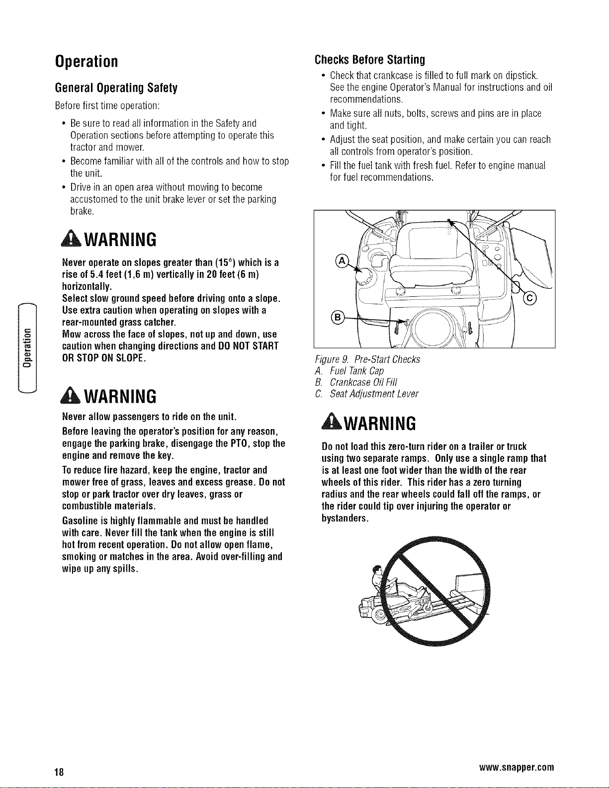
ChecksBeforeStarting
• Checkthat crankcaseis filled to full mark on dipstick.
Seethe engine Operator'sManualfor instructions and oil
recommendations.
• Makesureall nuts, bolts, screws and pins are in place
and tight.
• Adjust the seatposition, and makecertain you can reach
all controls from operator's position.
° Fillthe fueltank with fresh fuel. Referto engine manual
for fuel recommendations.
Figure9. Pre-Start Checks
A. Fuel TankCap
B. CrankcaseOilFill
C. SeatAdjustment Lever
WARNING
Do notloadthis zero-turnrider on a trailer ortruck
usingtwoseparateramps. Onlyusea single rampthat
isat leastone foot widerthanthewidth of therear
wheels ofthis rider. Thisrider hasa zeroturning
radiusandthe rear wheels could fall off theramps, or
therider could tip over injuringtheoperatoror
bystanders.
18 www.snapper.com
, WARNING
If youdo notunderstandhowa specificcontrol
functions,or havenotyet thoroughlyread the
FEATURES& CONTROLSsection, dosonow.
Do NOT attempttooperate thetractorwithoutfirst
becomingfamiliar with the locationandfunction of ALL
controls.
StartingtheEngine
1. While sitting in the operator'sseat,engagethe parking
brakeand makesurethe PTOswitch is disengagedand
the ground speed/ steering control levers are locked in
the NEUTRALposition.
2. NOTE:A warmenginemay notre#uire choking.
Setthe engine throttle control to FASTthrottle position.
Thenfully closethe chokeby pulling the knob OUTfully.
3. Insertthe key intothe ignition switch and turn it to
START.
4. After the engine starts, gradually openthe choke (push
knob downfully). Reduceto half throttle speedand
allow the engineto warm up.
Warm up the engineby running it for at least a minute before
engaging the PTOswitch or driving therider,
5. Afterwarmingthe engine,ALWAYSoperate the unitat
FULLTHROTTLEwhen mowing.
In theevent ofan emergency theengine canbe stopped by
simplytl/rningthe ignitionswitchtoSTOP. Usethis
method only in emergencysituations, For normal engine
shut down foflow theprocedure givenin STOPPINGTHE
RIDER.
Stoppingthe RiderandEngine
1. Returningthe ground speed/ steering control leversto
the middleposition will stop tractor movement. Pivot
the levers outward and lock them in NEUTRAL.
2. Disengagethe PTOby pushing down on the PTOswitch.
3. Engagethe parking brakeby pulling the handle up until it
locks into position.
4. Movethe throttle control to mid-throttle position and
turn the ignition keyto OFF.Removethe key.
®
DO NOT TOW RIDER
Towing the unit will causetransmission
damage. Do not useanother vehicleto push or
pull this unit.
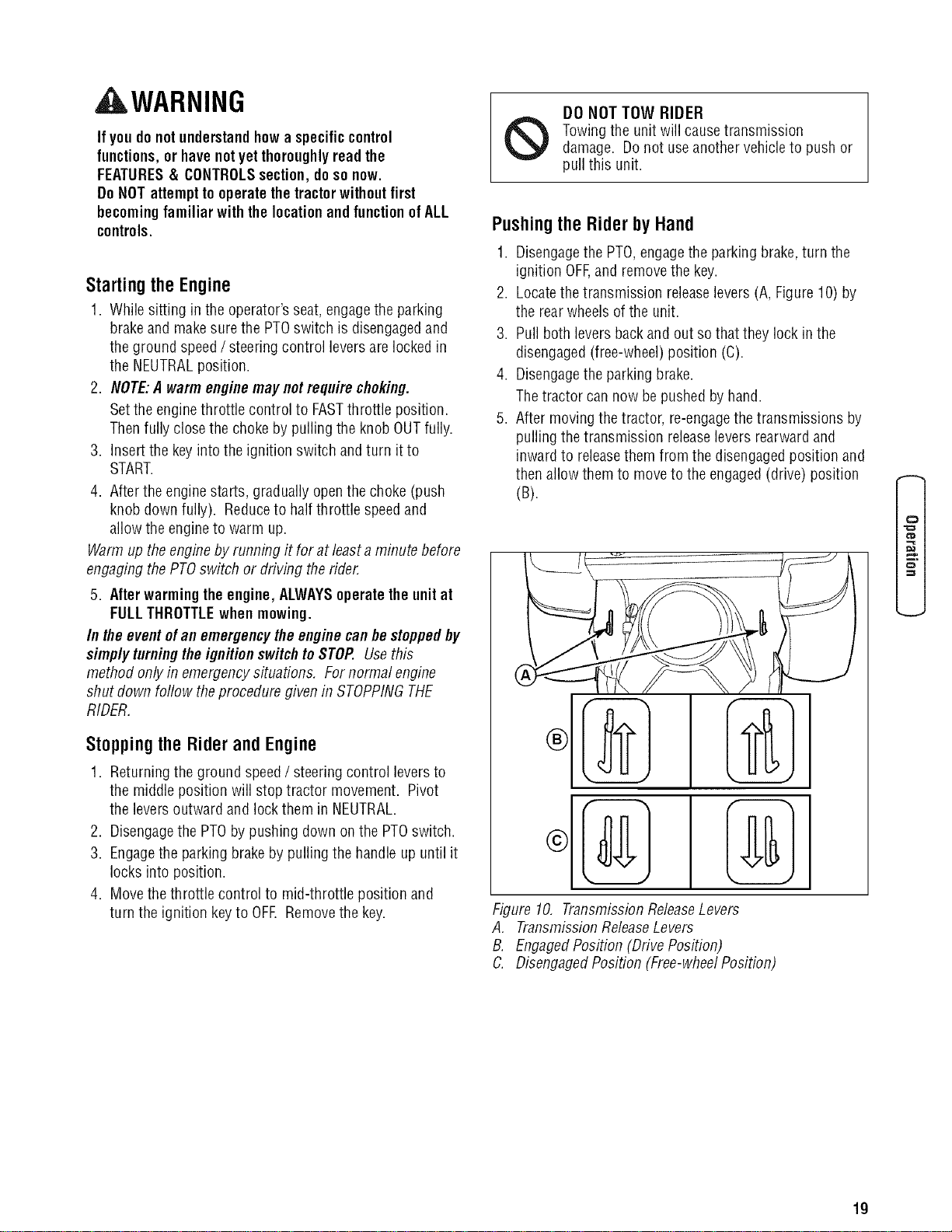
Pushing the Rider by Hand
1. Disengagethe PTO,engagethe parking brake,turn the
ignition OFF,and removethe key.
2. Locatethetransmission releaselevers (A, Figure10) by
the rearwheels of the unit.
3. Pull both levers back and out sothat they lock in the
disengaged(free-wheel) position (C).
4. Disengagethe parking brake.
Thetractor cannow be pushedby hand.
5. After moving the tractor, re-engagethe transmissions by
pulling the transmission releaselevers rearward and
inwardto releasethem from the disengagedposition and
then allow them to move to the engaged(drive) position
(B).
Figure 10. TransmissionReleaseLevers
A, TransmissionReleaseLevers
B. EngagedPosition (Drive Position)
C. DisengagedPosition (Free-wheelPosition)
0
f_
19
o
Zero-TurnDrivingPractice
Thelevercontrols of the ZeroTurn rider are responsive,
and learningto gain a smooth and efficient control of the
rider's forward, reverse,andturning movementswill take
some practice.
Spending sometime going through the maneuversshown
and becoming familiar with howthe unitaccelerates,
travels, and steers-- beforeyou begin mowing --is
absolutelyessentialto getting the most out of theZero Turn
rider.
Locatea smooth,flat area ofyourlawn -- onewith plenty
of roomto maneuver.(Clearthe areaof objects, peopleand
animals beforeyou begin.) Operatethe unit at mid-throttle
during this practicesession (ALWAYSoperateatfull
throttle when mowing), and turn slowly to preventtire
slippageand damageto your lawn.
Wesuggestyou begin with the Smooth Travelprocedureto
the right, and thenadvancethrough the forward, reverse,
and turning maneuvers.
You must releasethe parking brakeprior to movingthe
control levers inward.
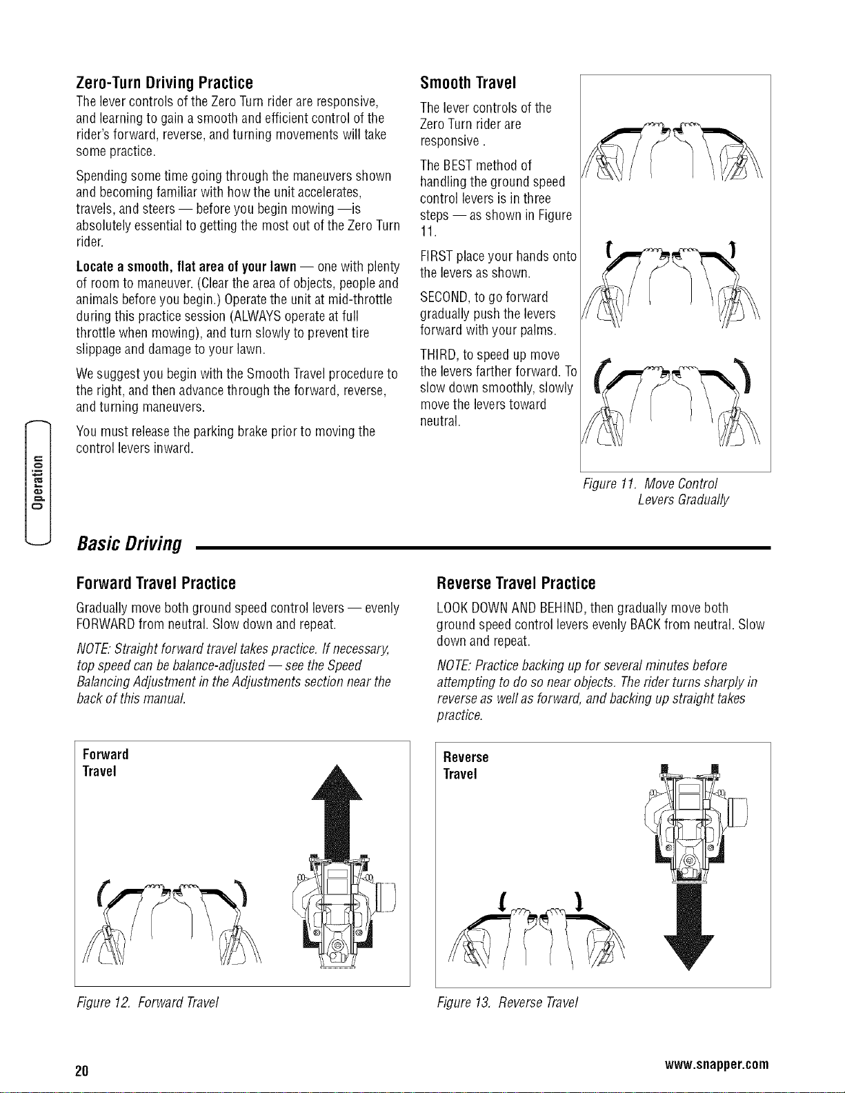
SmoothTravel
Thelevercontrols of the
ZeroTurn rider are
responsive.
TheBESTmethod of
handling the ground speed
control levers is in three
steps-- asshown in Figure
11.
FIRSTplaceyour handsonto
the leversas shown.
SECOND,to go forward
gradually pushthe levers
forward with your palms.
THIRD,to speed up move
the leversfarther forward. To
slow down smoothly, slowly
move the leverstoward
neutral.
Figure 11, Move Control
Levers Gradually
BasicDriving
ForwardTravelPractice
Graduallymove both ground speedcontrol levers-- evenly
FORWARDfrom neutral. Slow down and repeat.
NOTE."Straight forward travel takespractice. If necessary,
top speedcanbe balance-adjusted-- seethe Speed
BalancingAdjustment in theAdjustments section near the
back of this manual
ReverseTravelPractice
LOOKDOWNAND BEHIND,then gradually move both
ground speedcontrol levers evenly BACKfrom neutral. Slow
down and repeat.
NOTE.Practicebacking up for severalminutes before
attempting to do so nearobjects, Therider turns sharply in
reverseas weflas forward, and backing up straight takes
practice.
Forward
Travel
Reverse
Travel
Figure 12, Forward Travel Figure 13, ReverseTravel
20 www.snapper.com
Practice TurningArounda Corner
Whiletraveling forward bring one handle graduallyback
toward neutral. Repeatseveraltimes.
NOTE."Toprevent pivoting directly on thetire tread,it is best
to keepboth wheelsgoing at least slightly forward.
Practice TurningInPlace
Toturn in place, "Zero Turn,"gradually move one ground
speedcontrol leverforward from neutral andoneleverback
from neutral simultaneously. Repeatseveraltimes.
NOTE."Changingtheamount eachlever ispulled--forward or
back, changesthe "pivot point" you turn on.
Executing
Turns
Figure 14, TurningAround a Corner
Turning
In-Place
Figure 15, Turningin Place
AdvancedDriving
Executingan End-Of-RowZero Turn
Your ZeroTurnRider's uniqueabilityto turn in
placeallows you to turn around atthe end of a
cutting row ratherthan havingto stop and Y-turn
beforestarting a new row.
Forexample,to executea left end-of row zero
turn:
1. Slow downat the end of the row.
2. Movethe RIGHTground speedcontrol lever
forward slightly while moving the LEFT
ground speedcontrol leverbackto center and
then slightly back from center.
3. Begin mowing forward again.
This techniqueturns the rider LEFTand slightly
overlapsthe rowjust cut --eliminating the need
to back up and re-cut missedgrass.
Asyou becomemore familiar and experienced
with operatingtheZero Turnrider,you will learn
more maneuversthat will makeyour mowing time
easierand more enjoyable.
Remember,themore youpractice,the better
yourcontrolof theZeroTurnwill be!
0
f_
Figure 16, Executingan End-Of-Row Turn
21
o
MowerRemovalandInstallation
NOTE.Perform mower deck installation and removal on a
hard flat surface such asa concretefloor,
Removal
1. Disengagethe PTO,engagetheparking brake,turn off
the ignition, removethe key,andwait for all moving
parts to stop.
2. Removethe cutting height pin and lower the attachment
lift to its lowest position.
3. Removethe mower deckguards.
WARNING
Useextremecautionwhen rotatingtheidler armwith
the breakerbar, dueto increasedtensionin the spring
as theidler armis being rotated. Injurymay resultif
the breakerbar is prematurelyreleasedwhile the
springisundertension.
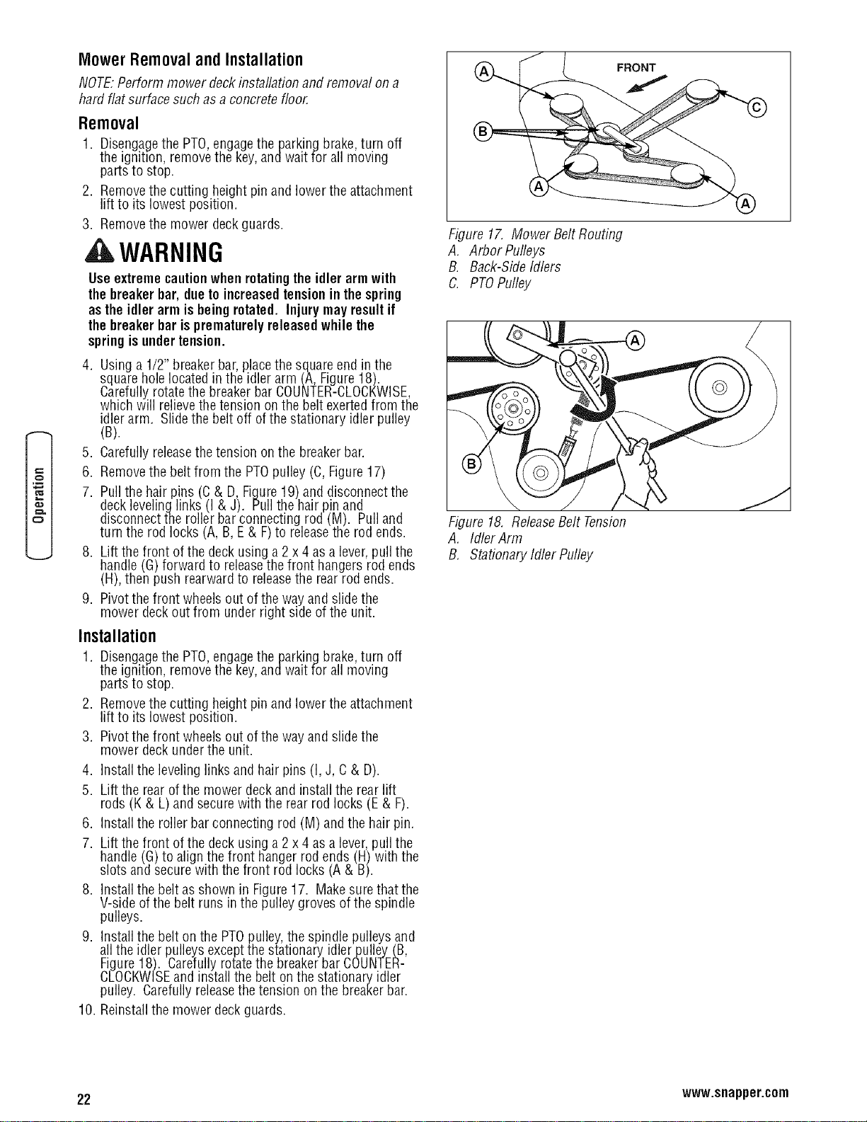
4. Using a 1/2" breakerbar,placethe squareend in the
square hole located in the idler arm (A, Figure18).
Carefullyrotatethe breakerbar COUNTER-CLOCKWISE,
which will relievethetension on the belt exerted from the
idler arm. Slide the belt off of the stationary idler pulley
(B).
5. Carefullyreleasethe tension on the breakerbar.
6. Removethe belt from the PTOpulley (C, Figure17)
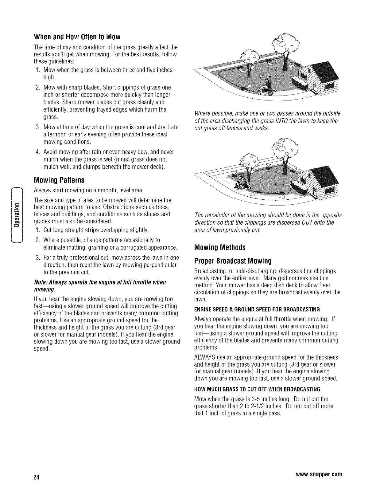
7. Pull the hair pins (C& D, Figure19) and disconnectthe
decklevelinglinks (I & J). Pull the hair pin and
disconnectthe roller barconnecting rod (M). Pull and
turn the rod locks (A, B,E & F)to releasethe rod ends.
8. Lift the front of the deck using a 2 x 4 as a lever,pull the
handle(G) forward to releasethefront hangers rod ends
(H), then push rearwardto releasethe rear rod ends.
9. Pivot thefront wheels out of the way and slidethe
mower deck out from under right sideof the unit.
Installation
1. Disengagethe PTO,engagetheparking brake,turn off
the ignition, removethe key,andwait for all moving
parts to stop.
2. Removethe cutting height pin and lower the attachment
lift to its lowest position.
3. Pivot thefront wheels out of the way and slidethe
mower deck under the unit.
4. Installthe levelinglinks and hair pins (I, J, C& D).
5. Lift the rear ofthe mower deck and install the rear lift
rods (K & L) and securewith the rear rod locks (E & F).
6. Installthe roller bar connecting rod (M) and the hair pin.
7. Lift the front of the deck using a 2 x 4 as a lever,pull the
handle(G) to align thefront hanger rod ends (H) with the
slots and securewith the front rod locks (A & B).
8. Installthe beltas shown in Figure17. Makesurethat the
V-side ofthe belt runs in the pulley groves of the spindle
pulleys.
9. Installthe belt on the PTOpulley,the spindle pulleys and
all the idler pulleys exceptthe stationary idlerpulley (B,
Figure18). Carefully rotatethe breakerbar COUNTER-
CLOCKWISEand install the belt on the stationary idler
pulley. Carefullyreleasethe tension on the breakerbar.
10. Reinstallthe mower deck guards.
FRONT
Figure 17. Mower BeltRouting
A. Arbor Pulleys
B. Back-SideIdlers
C. PTOPulley
Figure 18, ReleaseBelt Tension
A, IdlerArm
B, Stationary Idler Pulley
22 www.snapper.com
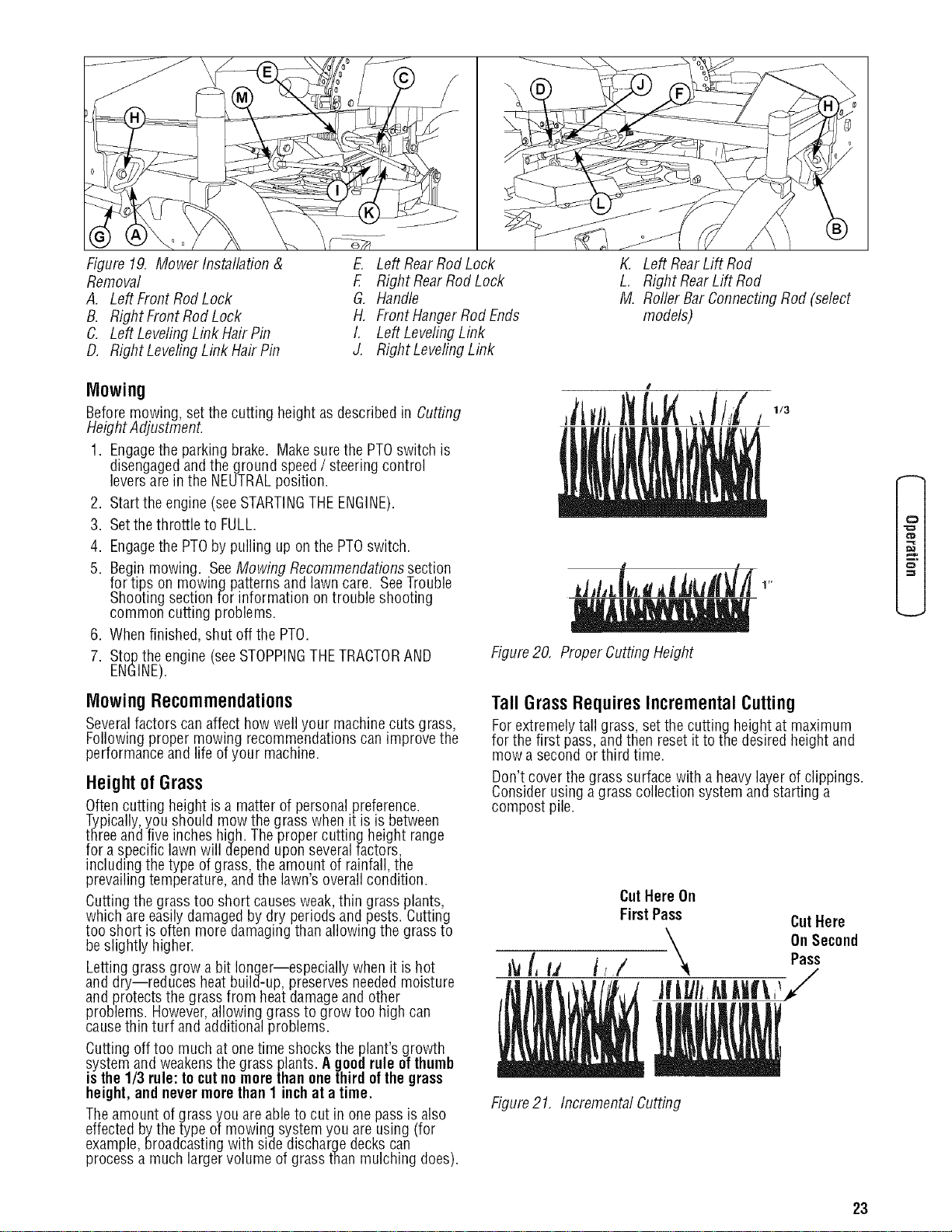
Figure 19. Mower Installation &
Removal
A, Left FrontRodLock
B. Right FrontRod Lock
C. Left LevelingLink Hair Pin
D, Right LevelingLink Hair Pin
E. LeftRearRod Lock
F. Right RearRod Lock
G, Handle
H. Front HangerRodEnds
I, Left LevelingLink
J. Right LevelingLink
Mowing
Beforemowing, setthe cutting height as described in Cutting
Height Adjustment.
1. Engagethe parking brake. Makesurethe PTOswitch is
disengagedandthe ground speed/ steering control
leversare in the NEUTRALposition.
2. Startthe engine (seeSTARTINGTHEENGINE).
3. Setthe throttle to FULL.
4. Engagethe PTOby pulling up onthe PTOswitch.
5. Begin mowing. SeeMowing Recommendationssection
for tips on mowing patternsand lawn care. SeeTrouble
Shootingsection for information on trouble shooting
common cutting problems.
6. When finished, shut off the PTO.
7. Stopthe engine (seeSTOPPINGTHETRACTORAND
ENGINE).
MowingRecommendations
Severalfactors canaffect howwell your machine cuts grass,
Following proper mowing recommendationscan improve the
performanceand life ofyour machine.
Height of Grass
Oftencutting height is a matter of personalpreference.
Typically,you should mow the grass when it is is between
threeand five inches high. Theproper cutting height range
for a specific lawn will dependupon severalfactors,
including the type ofgrass, the amount of rainfall, the
prevailingtemperature, and the lawn's overallcondition.
Cuttingthe grass too short causesweak,thin grass plants,
which areeasily damagedby dry periods and pests. Cutting
too short is often more damagingthan allowing the grass to
be slightly higher.
Letting grass grow a bit longer--especially when it is hot
and dry--reduces heatbuild-up, preservesneeded moisture
and protects the grass from heatdamageand other
problems. However,allowing grass to grow too high can
causethin turf and additional problems.
Cutting off too much at onetime shocks the plant's growth
system and weakensthe grass plants. Ageod rule ofthumb
is the1/3 rule:to cutnomorethan onethird ofthegrass
height,and nevermorethan 1 inchat a time.
Theamount ofgrass you areable to cut in one pass is also
effected bythe type of mowing systemyou are using (for
example,broadcastingwith side discharge deckscan
processa much larger volume of grass than mulching does).
K, Left RearLift Rod
L, Right RearLift Rod
M. Roller Bar ConnectingRod (select
models)
I
,itwJ), ,,//i,
J J
Figure20, Proper Cutting Height
TallGrassRequiresIncrementalCutting
Forextremely tall grass, set the cutting heightat maximum
for the first pass,and then resetit to the desiredheight and
mow a second or third time.
Don't coverthe grasssurface with aheavylayerof clippings.
Consider usinga grass collection system andstarting a
compost pile.
[,u
CutHere On
FirstPass CutHere
'_ On Second
t_' ,/ Pass
Figure21, Incremental Cutting
0
f_
23
o
When and How Often to Mow
Thetime of dayand condition ofthe grass greatly affect the
results you'll get when mowing. Forthe bestresults,follow
theseguidelines:
1. Mow when the grass is betweenthree and five inches
high.
2. Mow with sharpblades. Short clippings of grass one
inch or shorter decompose more quicklythan longer
blades.Sharp mower bladescut grass cleanly and
efficiently, preventing frayed edgeswhich harm the
grass.
3. Mow at time of daywhen the grass is cool and dry. Late
afternoon or early eveningoften providethese ideal
mowing conditions.
4. Avoid mowing after rain or even heavydew,and never
mulch whenthe grass is wet (moist grass doesnot
mulch well, and clumps beneaththe mower deck).
MowingPatterns
Alwaysstart mowing on a smooth, levelarea.
Thesizeand type ofareato be mowed will determine the
best mowing pattern to use. Obstructions such astrees,
fencesand buildings, and conditions such asslopes and
gradesmust also be considered.
1. Cutlong straight strips overlappingslightly.
2. Where possible,changepatterns occasionallyto
eliminate matting, graining or a corrugated appearance.
3. Foratruly professional cut, mow acrossthe lawn in one
direction, then recut the lawn by mowing perpendicular
to the previous cut.
Note:Alwaysoperatetheengineat full throttlewhen
mowing.
If you hearthe engine slowing down, you are mowing too
fast--using a slower ground speedwill improve the cutting
efficiency ofthe bladesand preventsmany common cutting
problems. Usean appropriateground speedfor the
thickness and height ofthe grass you arecutting (3rd gear
or slower for manualgear models). If you hear the engine
slowing down you are mowing too fast, usea slower ground
speed.
Wherepossible, make one or two passesaround theoutside
of theareadischarging thegrass INTOthelawn to keepthe
cut grass off fencesand walks,
Theremainder of the mowing should be done in the opposite
direction so that the clippings are dispersed OUTonto the
area of lawnpreviously cut.
Mowing Methods
ProperBroadcastMowing
Broadcasting, or side-discharging, dispersesfine clippings
evenly overthe entire lawn. Manygolf courses usethis
method. Your mower hasa deepdish deck to allow freer
circulation of clippings sothey are broadcastevenly overthe
lawn.
ENGINESPEED&GROUNDSPEEDFORBROADCASTING
Alwaysoperatethe engineat full throttle when mowing. If
you hearthe engine slowing down, you are mowing too
fast--using a slower ground speedwill improve the cutting
efficiency of the bladesand preventsmany common cutting
problems.
ALWAYSusean appropriateground speedfor the thickness
and height of the grassyou arecutting (3rd gear or slower
for manualgear models). If you hearthe engine slowing
down you are mowing too fast, usea slower ground speed.
HOWMUCHGRASSTOCUTOFFWHENBROADCASTING
Mow whenthe grass is 3-5 inches long. Do not cut the
grass shorter than 2 to 2-1/2 inches. Do not cut off more
that 1 inch of grass in a single pass.
24 www.snapper.com
Proper Mulching
Mulching consists of a mower deck which cuts and recuts
clippings into tiny particlesand which then blows them down
INTOthe lawn. Thesetiny particles decompose rapidlyinto
by-products your lawncan use. UNDERPROPER
CONDITIONS,your mulching mower will virtually eliminate
noticeableclippings on the lawnsurface.
NOTE:When mulching under heavycutting conditions, a
rumbling sound may be present and is normal.
MULCHINGREQUIRESEXCELLENTMOWINGCONDITIONS
Mulching mowerscannotfunction properly if thegrass is
wet, or if the grass is simply to high to cut. Evenmorethan
normal mowing, mulching requiresthat the grass be dry and
thethe appropriate amount iscut.
Do not usethe mower as a mulching mower during the first
two or three mowings in the spring. Thelong grass blades,
quick growth, and often wetterconditions are moresuitable
for broadcasting(side-discharging) or grass bagging
operation.
ENGINESPEED&GROUNDSPEEDFORBROADCASTING
Usefull enginethrottle matchedwith a slow ground speed
sothat clippings will be finely cut. Groundspeedwhile
mulching should be HALFof the speedthat would be used
when broadcasting (sidedischarging) under similar
conditions. Since mulching requiresmore horsepower than
broadcasting, usinga slower ground speed isvitally
important for proper mulching operation.
HOWMUCHGRASSTOMULCH
Thebest mulching action typically resultsfrom cutting only
thetop 1/2 inch to 3/4 inch of grass blade.This provides
short clippings which decomposeproperly (much more
quickly than longer clippings). Theideal cutting height will
vary with climate, time ofyear,and quality of your lawn. We
recommendthat you experimentwith boththe cutting height
and ground speeduntil you achievethe best cut. Start with a
high cutting heightand using progressively lowersettings
until you find a cutting heightthat is matchedto your
mowing conditions and preferences.
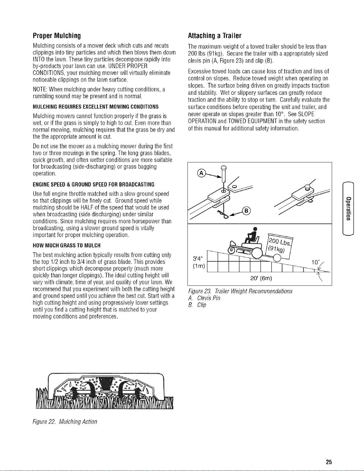
Attachinga Trailer
Themaximum weight of atowed trailer should be lessthan
200 Ibs (91kg). Securethe trailer with a appropriately sized
clevis pin (A, Figure23) and clip (B).
Excessivetowed loadscan causeloss of traction and loss of
control on slopes. Reducetowed weight when operating on
slopes. Thesurface being driven on greatly impacts traction
and stability. Wet or slippery surfaces cangreatly reduce
traction and the ability to stop or turn. Carefullyevaluatethe
surfaceconditions before operatingthe unitand trailer, and
neveroperateon slopes greaterthan 10°. SeeSLOPE
OPERATIONand TOWEDEQUIPMENTin the safetysection
of this manualfor additional safety information.
o/
®
3,4,,
(lm)
20' (6m) ?
Figure23. TrailerWeightRecommendations
A. ClevisPin
B. Clip
0
t_D
Figure22, Mulching Action
25

Maintenance
MaintenanceSchedule& Procedures
Thefollowing schedule should be followed for normalcare of your rider and mower.You will needto keepa record ofyour
operatingtime. Determiningoperatingtime is easilyaccomplished by observing the elapsedtime recordedby the hour meter.
SAFETYITEMS Before Every5 Every25 Every 100 Every Spring &
Each Hours Hours Hours 200 Fall
Use Hours
CheckSafety Interlock System . .
CheckMower BladeStopping Time • •
RIDER MAINTENANCEITEMS Before Every5 Every25 Every 100 Every Spring &
Each Hours Hours Hours 200 Fall
Use Hours
CheckRider/ Mower for loosehardware °
Check/ CleanEngineCooling Fins •
Check/ Adjust PTOClutch •
Lubricate Rider & Mower ** °
CleanBattery& Cables .
CheckTire Pressure .
CleanDeck& ChecWReplaceMowerBlades** .
CheckTransmission Oil •
ChangeTransmission Oil Filter ** •
ENGINE MAINTENANCEITEMS Before Every5 Every25 Every 100 Every Spring &
Each Hours Hours Hours 200 Fall
Use Hours
CheckEngineOil Level •
Check/Change EngineAir Filter *
ChangeEngineOil & Filter *
Inspect Spark Plug(s) *
Check/ ReplaceFuelFilter *
* Referto engine owner's manual. Changeoriginal engine oil after initial break-inperiod.
** More often in hot (over 85° F:30° C)weather or dusty operating conditions.
26 www.snapper.com
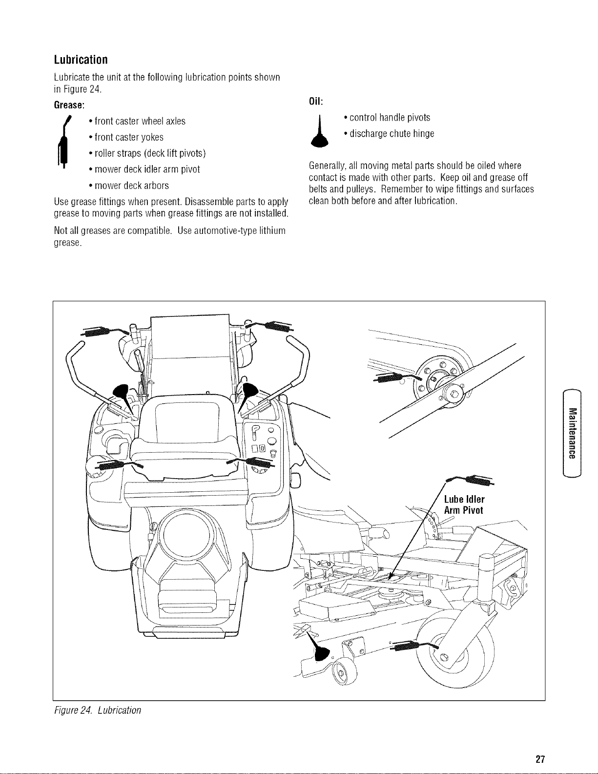
Lubrication
Lubricate the unit atthe following lubrication points shown
in Figure24.
Grease:
i_ • front casterwheel axles
• front casteryokes
• roller straps (decklift pivots)
• mower deckidlerarm pivot
• mower deckarbors
Usegreasefittings whenpresent. Disassembleparts to apply
greaseto moving parts when greasefittings are not installed.
Not all greases arecompatible. Useautomotive-type lithium
grease.
Oil:
•control handle pivots
• dischargechute hinge
Generally,all moving metal parts should be oiled where
contact is madewith other parts. Keepoil and greaseoff
belts and pulleys. Rememberto wipe fittings and surfaces
cleanboth beforeand after lubrication.
Idler
Arm Pivot
=z
f_
Figure24. Lubrication
27
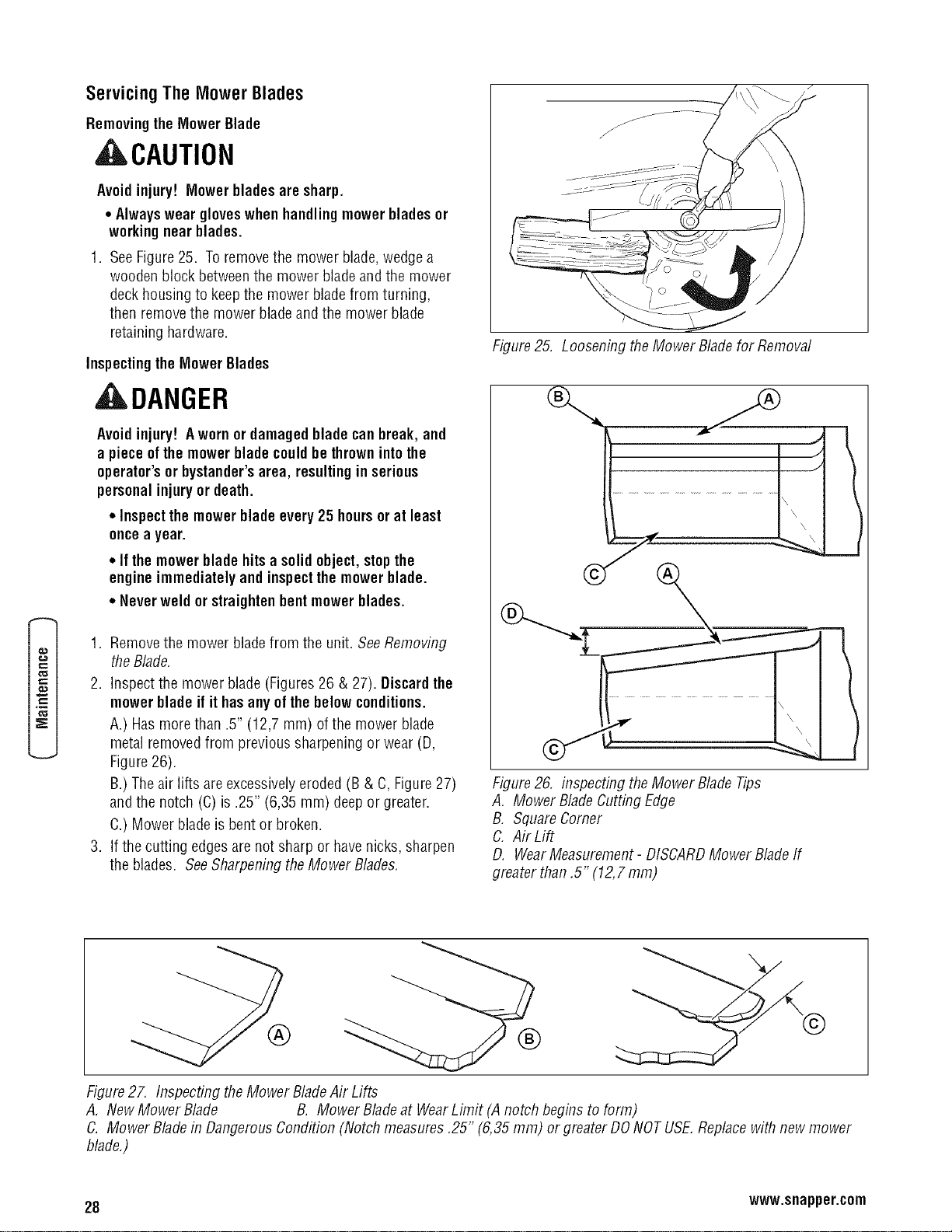
Servicing The MowerBlades
Removingthe MowerBlade
ACAUTION
Avoidinjury! Mower bladesare sharp.
• Alwayswear gloveswhen handlingmowerbladesor
working near blades.
1. SeeFigure25. Toremovethe mower blade,wedgea
wooden block betweenthe mower blade andthe mower
deckhousing to keepthe mower bladefrom turning,
then removethe mower bladeand the mower blade
retaininghardware.
Inspectingthe MowerBlades
ADANGER
Avoidinjury! Awornor damagedbladecanbreak, and
a piece ofthemowerbladecould be thrownintothe
operator's or bystander'sarea, resultingin serious
personal injuryor death.
• Inspectthe mowerblade every25 hoursor at least
once a year.
• Ifthe mowerblade hitsa solid object, stopthe
engineimmediately and inspectthe mowerblade.
• Never weld or straightenbentmowerblades.
1. Removethe mower bladefrom the unit. SeeRemoving
the Blade.
2. Inspectthe mower blade (Figures 26 & 27). Discard the
mowerbladeif it hasanyofthe belowconditions.
A.) Hasmorethan .5" (12,7 mm) of the mower blade
metal removedfrom previous sharpening or wear (D,
Figure26).
B.)Theair lifts areexcessivelyeroded (B & C, Figure27)
and the notch (C) is .25" (6,35 ram) deeporgreater.
C.) Mower blade is bent or broken.
3. If the cutting edgesare not sharp or havenicks, sharpen
the blades. SeeSharpening the Mower Blades.
Figure25. Loosening theMower Bladefor Removal
Figure26. inspecting the Mower Blade Tips
A, Mower Blade CuttingEdge
B, SquareComer
C. Air Lift
D. WearMeasurement- DISCARDMower Blade If
greater than,5" (12,7 mm)
®
®
Figure27. Inspecting theMower BladeAir Lifts
A, New Mower Blade B. Mower Bladeat WearLimit (A notch beginsto form)
C. Mower Bladein DangerousCondition (Notch measures,25" (6,35 mm) or greaterDONOTUSE.Replacewith new mower
blade,)
28 www.snapper.com
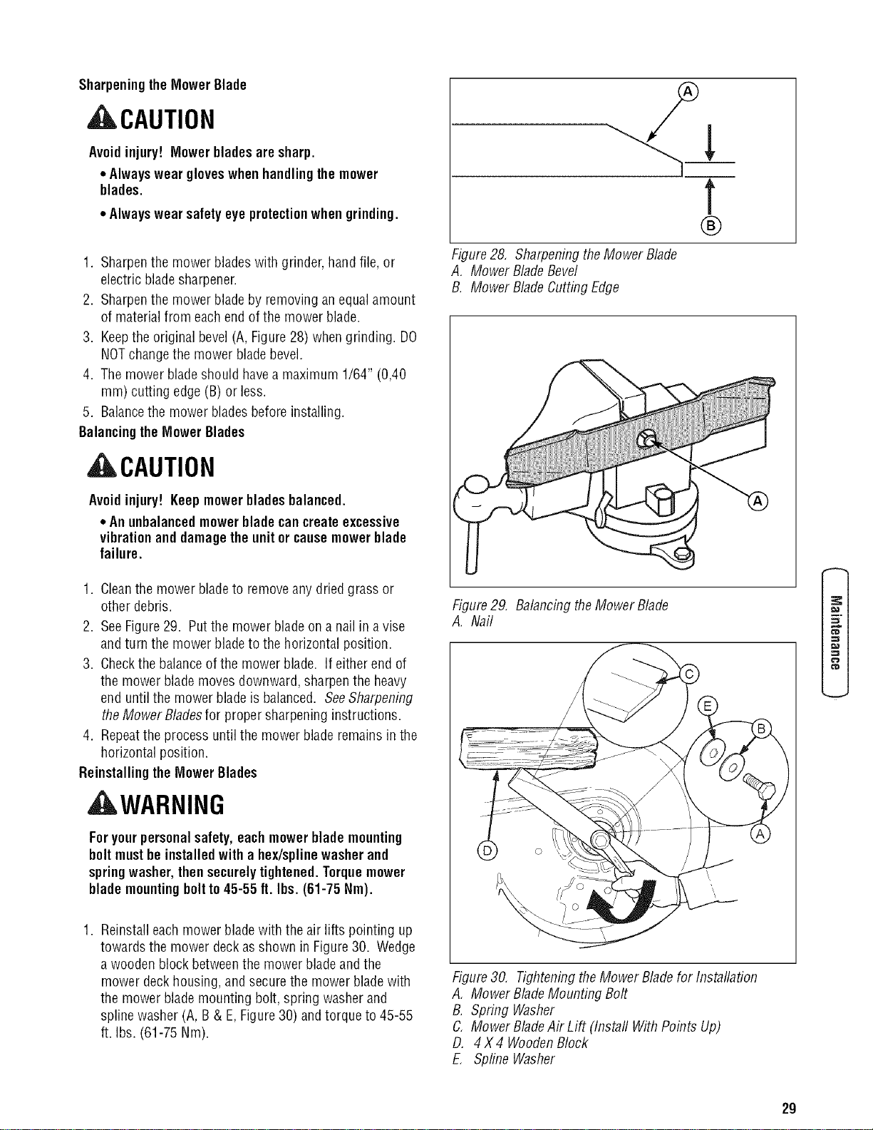
SharpeningtheMowerBlade
ACAUTION
Avoidinjury! Mower bladesare sharp.
• Alwayswear gloveswhen handlingthemower
blades.
• Alwayswear safety eye protectionwhengrinding.
1. Sharpenthe mower bladeswith grinder, hand file, or
electric blade sharpener.
2. Sharpenthe mower blade by removing an equal amount
of material from eachend of the mower blade.
3. Keepthe original bevel (A,Figure28) whengrinding. DO
NOTchangethe mower bladebevel.
4. The mower blade should havea maximum 1/64" (0,40
mm) cutting edge (B) or less.
5. Balancethe mower bladesbefore installing.
BalancingtheMower Blades
,ACAUTION
Avoidinjury! Keep mowerbladesbalanced.
• An unbalancedmowerbladecan create excessive
vibrationanddamagethe unitor cause mowerblade
failure.
1. Cleanthe mower bladeto remove anydried grass or
other debris.
2. SeeFigure29. Putthe mower blade on a nail in a vise
and turn the mower bladeto the horizontal position.
3. Checkthe balanceof the mower blade. If either end of
the mower blade movesdownward, sharpenthe heavy
end until the mower bladeis balanced. SeeSharpening
the Mower Bladesfor proper sharpeninginstructions.
4. Repeatthe process until the mower blade remains in the
horizontal position.
ReinstallingtheMower Blades
, WARNING
Foryourpersonalsafety,eachmowerblade mounting
boltmustbeinstalledwith a hex/splinewasherand
springwasher,then securelytightened.Torquemower
blade mountingboltto45-55 ft. Ibs. (61-75 Nm).
1. Reinstalleachmower blade with the air lifts pointing up
towards the mower deck asshown in Figure30. Wedge
a wooden block betweenthe mower blade andthe
mower deck housing, and secure the mower bladewith
the mower blade mounting bolt, spring washer and
spline washer (A, B & E, Figure30) andtorque to 45-55
ft. Ibs. (61-75 Nm).
!
®
Figure28, Sharpeningthe Mower Blade
A, Mower BladeBevel
B. Mower Blade CuttingEdge
Figure29, Balancingthe Mower Blade
A. Nail
Figure30. Tightening theMower Bladefor Installation
A, Mower BladeMounting Bolt
B. Spring Washer
C. Mower BladeAir Lift (Instafl With Points Up)
D, 4 X 4 WoodenBlock
E. Spline Washer
¢"D
29
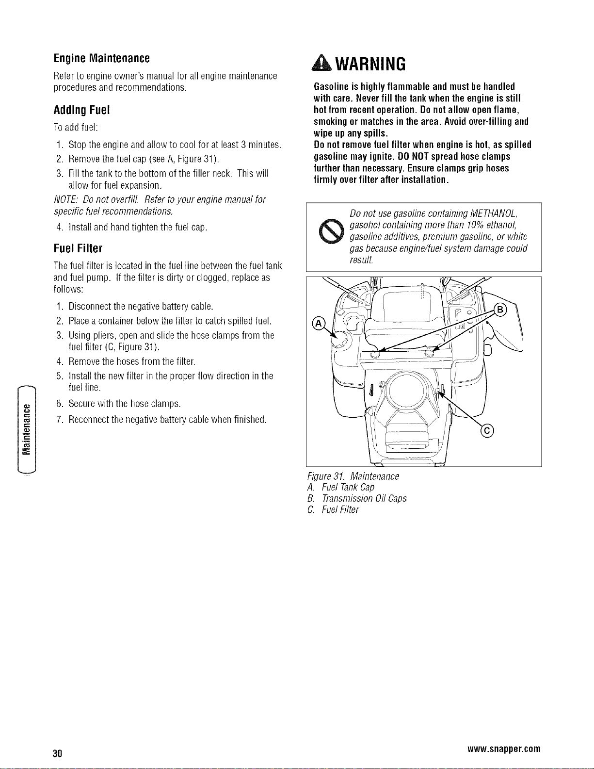
EngineMaintenance
Referto engine owner's manualfor all engine maintenance
procedures and recommendations.
Adding Fuel
Toadd fuel:
1. Stopthe engine andallow to cool for at least3 minutes.
2. Removethe fuel cap (seeA, Figure31).
3. Fillthetank to the bottom of the filler neck. This will
allow for fuel expansion.
NOTE."Do not overfill. Refertoyour enginemanual for
specific fuel recommendations.
4. Install and handtighten the fuel cap.
Fuel Filter
Thefuel filter is located in the fuel line betweenthe fueltank
and fuel pump. If the filter is dirty or clogged, replaceas
follows:
1. Disconnectthe negativebatterycable.
2. Placea container belowthe filter to catch spilled fuel.
3. Using pliers, open and slide the hoseclamps from the
fuel filter (C, Figure31).
4. Removethe hoses from the filter.
5. Installthe newfilter in the proper flow direction in the
fuel line.
6. Securewith the hoseclamps.
7. Reconnectthe negative batterycablewhen finished.
A WARNING
Gasolineis highlyflammable andmustbe handled
with care. Never fill the tankwhenthe engineis still
hotfrom recentoperation. Donotallow open flame,
smokingor matchesin the area. Avoidover-fillingand
wipe up anyspills.
Do notremovefuel filter whenengine ishot, as spilled
gasolinemay ignite. DONOTspreadhoseclamps
further thannecessary.Ensureclamps grip hoses
firmly over filter afterinstallation.
Do not usegasoline containing METHANOL,
_ asohol containing more than 10% ethanol,
gasolineadditives, premium gasoline, or white
gasbecauseengine/fuel system damagecould
result.
...... i:J
Figure31. Maintenance
A, Fuel TankCap
B. TransmissionOil Caps
C. FuelFilter
30 www.snapper.com
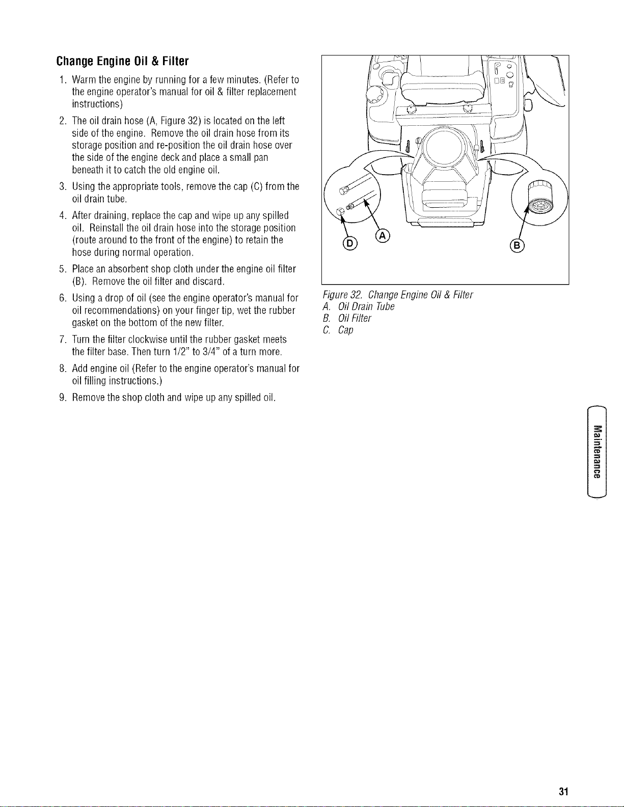
ChangeEngineOil & Filter
1. Warm the engine by running for afew minutes. (Referto
the engine operator's manualfor oil & filter replacement
instructions)
2. The oil drain hose (A, Figure32) is located on the left
side of the engine. Removethe oil drain hosefrom its
storage position and re-position the oil drain hoseover
the side of the engine deckand placea small pan
beneathit to catchthe old engine oil.
3. Usingthe appropriatetools, removethe cap (C)from the
oil drain tube.
4. After draining, replacethe cap and wipe up anyspilled
oil. Reinstallthe oil drain hoseinto the storage position
(route around to the front of the engine) to retainthe
hoseduring normal operation.
5. Placean absorbent shop cloth under the engineoil filter
(B). Removethe oil filter and discard.
6. Using a drop of oil (seethe engineoperator's manualfor
oil recommendations)on your finger tip, wet the rubber
gasket on the bottom ofthe newfilter.
7. Turnthe filter clockwise until the rubber gasket meets
the filter base. Thenturn 1/2" to 3/4" of a turn more.
8. Add engine oil (Refer to the engine operator's manualfor
oil filling instructions.)
9. Removethe shop cloth and wipe up anyspilled oil.
Figure32. ChangeEngineOil & Filter
A, Oil Drain Tube
B, Oil Filter
C. Cap
f_
31
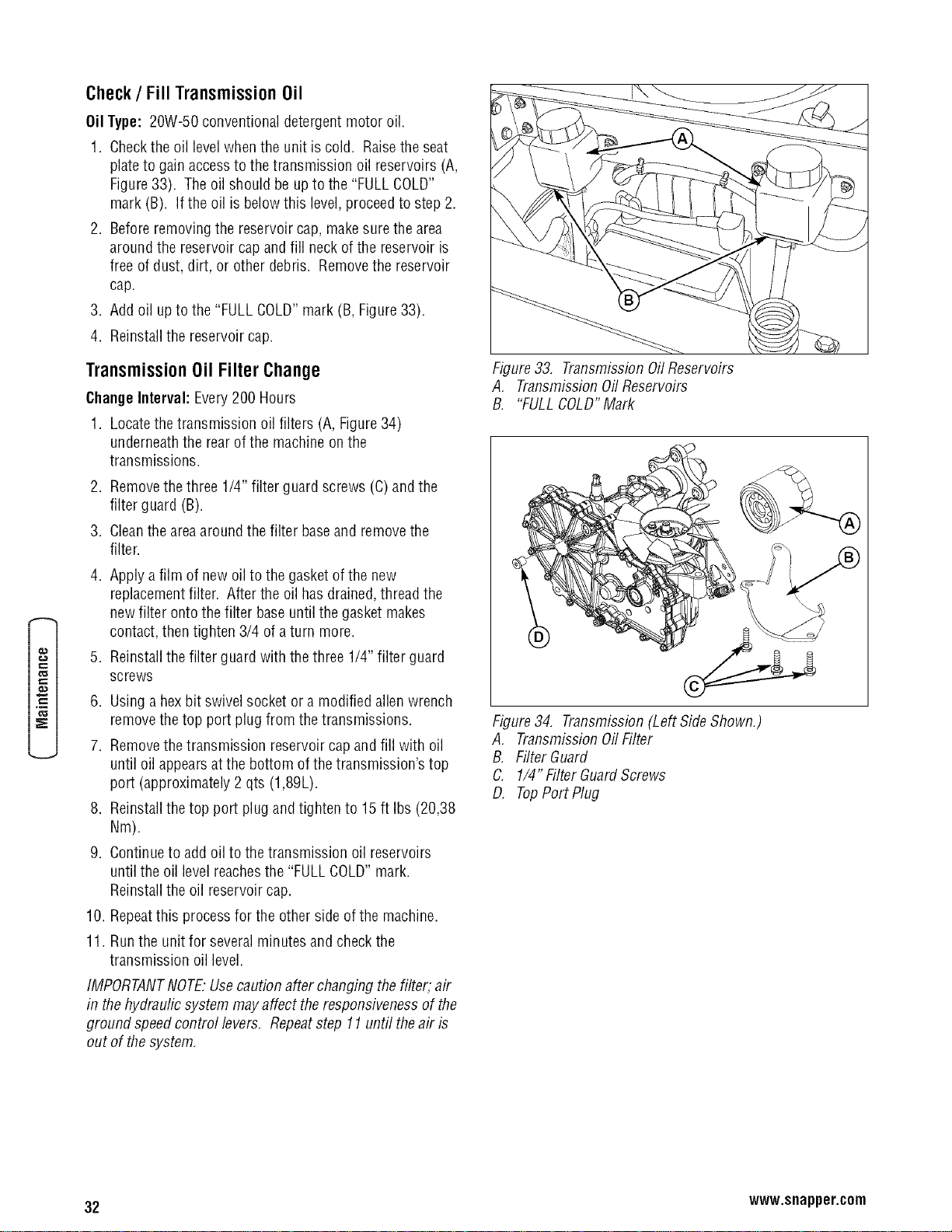
Check / Fill Transmission Oil
Oil Type: 20W-50 conventionaldetergent motor oil
1. Checkthe oil ]eve]whenthe unit iscold. Raisethe seat
plateto gain accessto the transmission oil reservoirs (A,
Figure33). Theoil should be upto the "FULL COLD"
mark (B). If the oil is belowthis level, proceedto step 2.
2. Beforeremoving the reservoir cap, makesurethe area
around the reservoir capand fill neckof the reservoir is
free of dust, dirt, or other debris. Removethe reservoir
cap.
3. Add oil upto the "FULLCOLD"mark (B, Figure33).
4. Reinstallthe reservoir cap.
Transmission Oil Filter Change
ChangeInterval: Every200 Hours
1. Locatethetransmission oil filters (A, Figure34)
underneaththe rearof the machine on the
transmissions.
,
3.
4.
Removethethree 1/4" filter guard screws (C)andthe
filter guard (B).
Cleanthe areaaround the filter baseand removethe
filter.
Apply a film of new oil to the gasketof the new
replacementfilter. After the oil hasdrained,thread the
newfilter ontothe filter baseuntil the gasketmakes
contact, then tighten 3/4 of a turn more.
5. Reinstallthe filter guard with the three 1/4" filter guard
screws
6. Using a hexbit swivel socket or a modified allen wrench
removethe top port plug from thetransmissions.
7. Removethetransmission reservoir capand fill with oil
until oil appearsat the bottom of thetransmission's top
port (approximately 2 qts (1,89L).
8. Reinstallthe top port plug and tighten to 15 ft Ibs (20,38
Nm).
9. Continueto add oil to the transmission oil reservoirs
until the oil levelreachesthe "FULL COLD"mark.
Reinstallthe oil reservoir cap.
10. Repeatthis processfor the other side ofthe machine.
11. Runthe unit for severalminutes and checkthe
transmission oil level.
IMPORTANTNOTE."Usecaution after changing the filter, air
in the hydraulic system may affect theresponsivenessof the
ground speedcontrol levers, Repeatstep 11 until theair is
out of the system,
Figure33,
A.
B.
Transmissbn Oil Reservoirs
TransmissionOil Reservoirs
"FULLCOLD"Mark
Figure34, Transmission(Left SideShown,)
A, TransmissionOil Filter
B. FilterGuard
C. 1/4" Filter GuardScrews
D, TopPort Plug
32 www.snapper.com
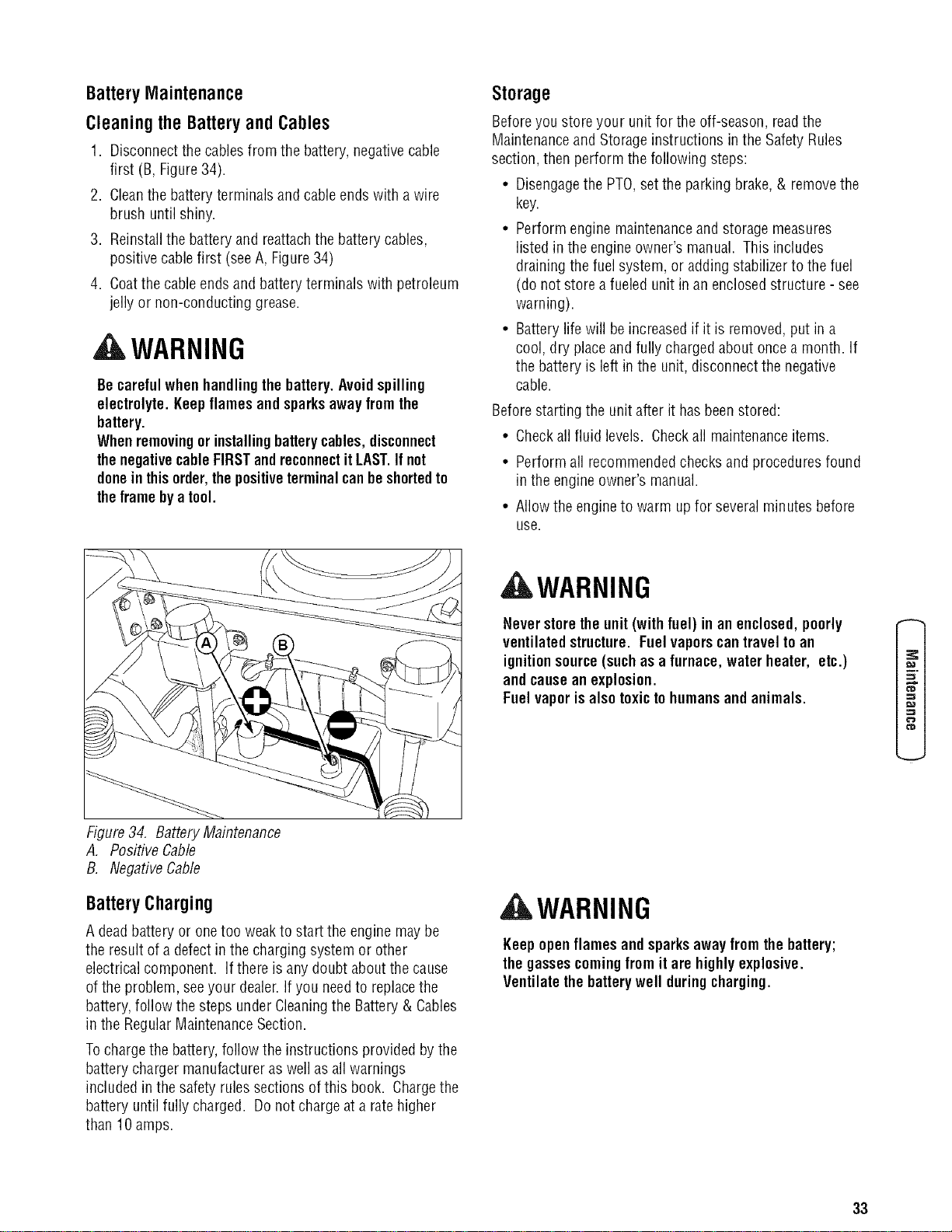
BatteryMaintenance
Cleaningthe BatteryandCables
1. Disconnectthe cables from the battery, negativecable
first (B, Figure34).
2. Cleanthe batteryterminals and cableendswith a wire
brush until shiny.
3. Reinstallthe batteryand reattachthe battery cables,
positivecablefirst (seeA, Figure34)
4. Coatthe cableends and batteryterminals with petroleum
jelly or non-conducting grease.
WARNING
Becarefulwhen handlingthe battery.Avoidspilling
electrolyte. Keepflames andsparksaway from the
battery.
Whenremovingorinstallingbatterycables, disconnect
thenegativecableFIRSTandreconnectitLAST.Ifnot
donein thisorder,thepositiveterminalcanbeshortedto
theframe bya tool.
Storage
Beforeyou store your unit for the off-season, readthe
Maintenanceand Storage instructions in the SafetyRules
section, then perform the following steps:
• Disengagethe PTO,set the parking brake, & remove the
key.
• Perform engine maintenanceand storage measures
listed in the engine owner's manual. This includes
draining the fuel system, or adding stabilizerto the fuel
(do not store a fueled unit in an enclosed structure - see
warning).
• Batterylife will be increasedif it is removed,put in a
cool, dry placeand fully charged about oncea month. If
the battery is left in the unit, disconnect the negative
cable.
Beforestarting the unit after it hasbeenstored:
• Checkall fluid levels. Checkall maintenanceitems.
• Perform all recommendedchecksand proceduresfound
in the engine owner's manual.
• Allow the engineto warm up for several minutes before
use.
_WARNING
Never storethe unit(with fuel) in anenclosed,poorly
ventilatedstructure. Fuelvaporscantravel to an
ignitionsource(suchas a furnace, waterheater, etc.)
andcause an explosion.
Fuelvaporisalso toxictohumansand animals.
=z
_D
Figure34. BatteryMaintenance
A. Positive Cable
B. NegativeCable
BatteryCharging
A deadbattery or onetoo weakto start the engine may be
the result of a defectin the charging system or other
electricalcomponent. If there is any doubt aboutthe cause
of the problem, seeyour dealer.If you needto replacethe
battery,follow the steps under Cleaningthe Battery & Cables
in the RegularMaintenanceSection.
Tochargethe battery,follow the instructions provided bythe
battery charger manufactureras well asall warnings
included in the safety rules sections of this book. Chargethe
battery until fully charged. Do not chargeata ratehigher
than 10 amps.
WARNING
Keepopen flames andsparksawayfrom thebattery;
thegassescoming from it are highlyexplosive.
Ventilatethe batterywell duringcharging.
33
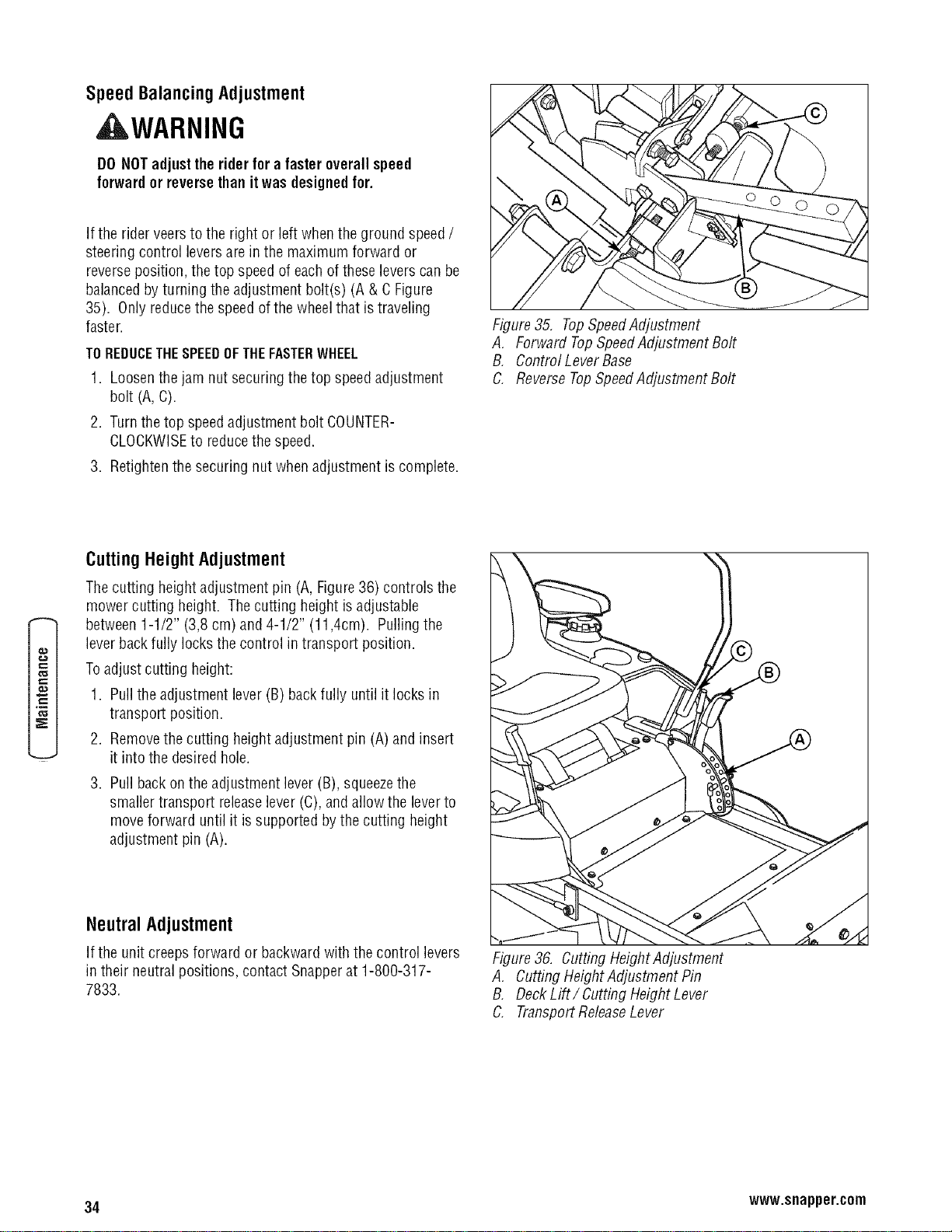
SpeedBalancingAdjustment
_WARNING
DO NOTadjusttherider for a fasteroverall speed
forward or reversethanit was designedfor.
If the rider veers to the right or left when the ground speed/
steering control leversare in the maximum forward or
reverseposition, the top speedof eachof these leverscan be
balancedbyturning the adjustment bolt(s) (A & C Figure
35). Only reducethe speedofthe wheelthat istraveling
faster.
TOREDUCETHESPEEDOFTHEFASTERWHEEL
1. Loosenthe jam nut securing thetop speedadjustment
bolt (A, C).
2. Turnthe top speedadjustment bolt COUNTER-
CLOCKWISEto reducethe speed.
3. Retightenthe securing nut when adjustment is complete.
Figure35. TopSpeedAdjustment
A, Forward TopSpeedAdjustment Bolt
B, Control LeverBase
C. ReverseTopSpeedAdjustment Bolt
CuttingHeightAdjustment
Thecutting heightadjustment pin (A, Figure36) controls the
mower cutting height. Thecutting height is adjustable
between 1-1/2" (3,8 cm) and4-1/2" (11,4cm). Pulling the
leverback fully locks the control in transport position.
Toadjust cutting height:
1. Pull the adjustment lever (B) back fully until it locks in
transport position.
2. Removethe cutting heightadjustment pin (A) and insert
it into the desired hole.
3. Pull back on the adjustment lever (B), squeezethe
smaller transport releaselever(C), and allow the leverto
move forward until it is supported bythe cutting height
adjustment pin (A).
NeutralAdjustment
If the unit creeps forward or backwardwith the control levers
in their neutral positions, contact Snapperat 1-800-317-
7833.
Figure36. Cutting HeightAdjustment
A, CuttingHeight Adjustment Pin
B, DeckLift/ Cutting HeightLever
C. TransportReleaseLever
34 www.snapper.com
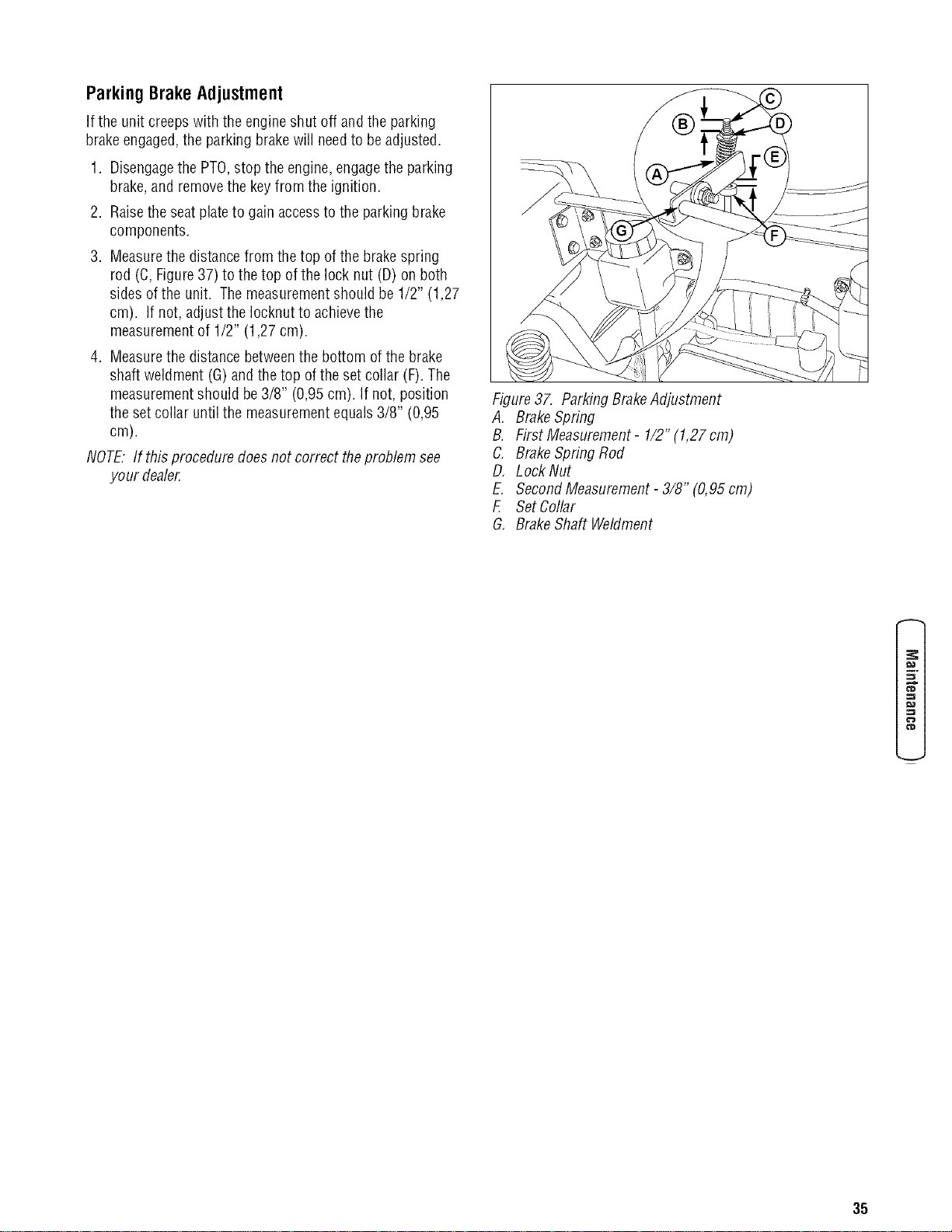
ParkingBrakeAdjustment
If the unit creeps with the engineshut off and the parking
brakeengaged,the parking brakewill needto beadjusted.
1. Disengagethe PTO,stop the engine,engagethe parking
brake,and remove the keyfrom the ignition.
2. Raisethe seat plateto gain accessto the parking brake
components.
3. Measurethe distancefrom thetop of the brakespring
rod (C, Figure37) to thetop of the lock nut (D) on both
sides ofthe unit. Themeasurementshould be 1/2" (1,27
cm). If not,adjustthe Iocknutto achievethe
measurementof 1/2" (1,27 cm).
4. Measurethe distancebetweenthe bottom ofthe brake
shaft weldment (G)and the top ofthe set collar (F). The
measurementshould be 3/8" (0,95cm). If not, position
the set collar until the measurementequals3/8" (0,95
cm).
NOTE."If this proceduredoes not correct theproblem see
your dealer.
Figure37. ParkingBrakeAdjustment
A, BrakeSpring
B. First Measurement- 1/2" (1,27 cm)
C. BrakeSpring Rod
D, Lock Nut
E. SecondMeasurement- 3/8" (0,95 cm)
F, Set Collar
G, BrakeShaft Weldment
f_
¢'D
tip
35
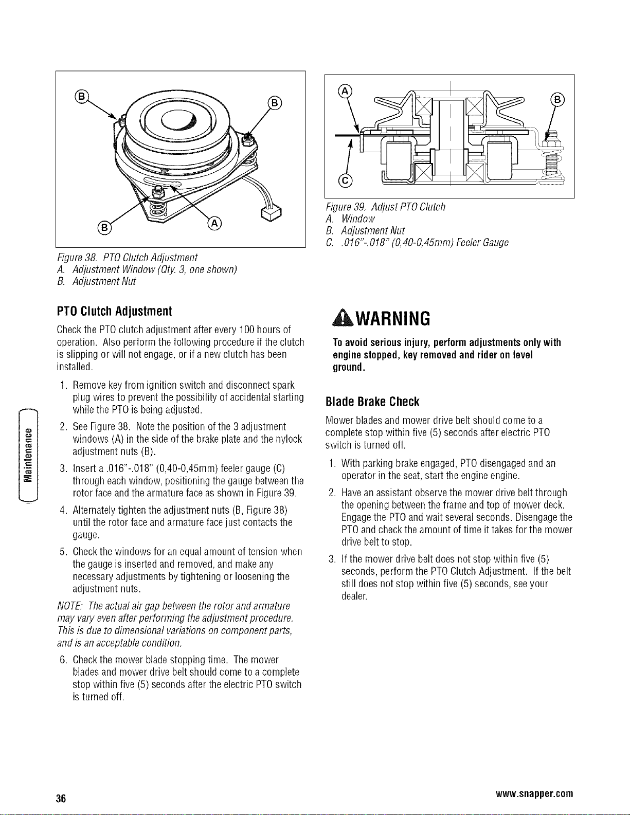
Figure38, PTOClutchAdjustment
A. Adjustment Window (Qty.3, one shown)
B, Adjustment Nut
Figure39. Adjust PTOClutch
A. Window
B. Adjustment Nut
C. .016"-,018" (0,40-0,45mm) FeelerGauge
PT0 Clutch Adjustment
Checkthe PTOclutch adjustment after every 100 hours of
operation. Also perform the following procedureif the clutch
is slipping or will not engage,or if a new clutch has been
installed.
1. Removekey from ignition switch and disconnectspark
plug wires to prevent the possibility of accidentalstarting
while the PTOis beingadjusted.
2. SeeFigure38. Notethe position ofthe 3 adjustment
windows (A) in the side ofthe brakeplateand the nylock
adjustment nuts (B).
3. Insert a .016"-.018" (0,40-0,45mm) feelergauge (C)
through eachwindow, positioning the gauge betweenthe
rotor face andthe armature face as shown in Figure39.
4. Alternatelytighten the adjustment nuts (B,Figure38)
until the rotor faceand armature facejust contactsthe
gauge.
5. Checkthe windows for anequal amount of tension when
the gauge is inserted and removed,and makeany
necessaryadjustments by tightening or looseningthe
adjustment nuts.
NOTE."Theactualairgapbetweentherotor and armature
may vary evenafter performing theadjustment procedure,
Thisis due to dimensional variationson component parts,
and is an acceptablecondition,
6. Checkthe mower blade stopping time. The mower
bladesand mower drive belt should come to a complete
stop within five (5) secondsafter the electric PTOswitch
isturned off.
AWARNING
Toavoidseriousinjury,perform adjustmentsonlywith
enginestopped,key removedandrider on level
ground.
BladeBrakeCheck
Mower bladesand mower drivebelt should come to a
completestop within five (5) secondsafter electric PTO
switch is turned off.
1. With parking brakeengaged,PTOdisengagedand an
operatorin the seat,start the engineengine.
2. Havean assistant observethe mower drive beltthrough
the opening betweenthe frame and top of mower deck.
Engagethe PTOandwait severalseconds. Disengagethe
PTOandcheckthe amount of time it takesfor the mower
drivebelt to stop.
3. If the mower drive belt doesnot stop within five (5)
seconds, perform the PTOClutchAdjustment. If the belt
still doesnot stop within five (5) seconds, seeyour
dealer.
36 www.snapper.com
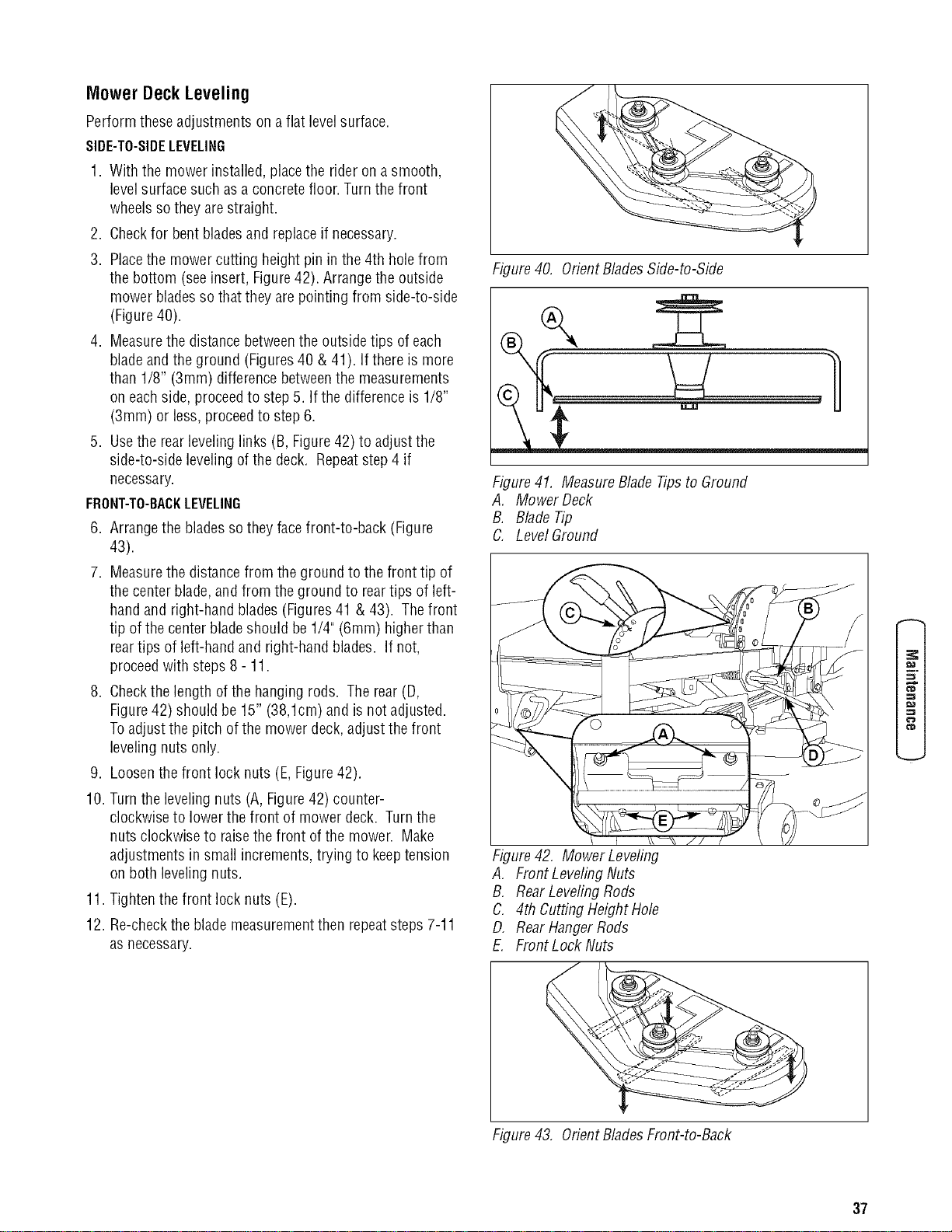
MowerDeckLeveling
Perform these adjustments on a flat levelsurface.
SIDE-TO-SIDELEVELING
1. With the mower installed,placethe rider on a smooth,
levelsurfacesuch asa concretefloor. Turnthe front
wheels so they are straight.
2. Checkfor bentbladesand replaceif necessary.
3. Placethe mower cutting height pin in the 4th holefrom
the bottom (seeinsert, Figure42). Arrange the outside
mower bladesso that they are pointing from side-to-side
(Figure40).
4. Measurethe distancebetweenthe outside tips of each
bladeand the ground (Figures40 & 41). If there is more
than 1/8" (3mm) difference betweenthe measurements
on eachside, proceedto step 5. If the difference is 1/8"
(3mm) or less, proceedto step 6.
5. Usethe rear levelinglinks (B, Figure42) to adjust the
side-to-side levelingof the deck. Repeatstep 4 if
necessary.
FRONT-TO-BACKLEVELING
6. Arrangethe bladessothey facefront-to-back (Figure
43).
7. Measurethe distancefrom the ground to the front tip of
the center blade,and from the ground to reartips of left-
handand right-hand blades(Figures41 & 43). Thefront
tip of the center bladeshould be 1/4" (6mm) higherthan
reartips of left-hand and right-hand blades. If not,
proceedwith steps 8 - 11.
8. Checkthe length ofthe hanging rods. Therear (D,
Figure42) should be 15" (38,1cm) and is not adjusted.
Toadjust the pitch of the mower deck,adjust the front
levelingnuts only.
9. Loosenthe front lock nuts (E,Figure42).
10. Turnthe leveling nuts (A, Figure42) counter-
clockwise to lowerthe front of mower deck. Turnthe
nuts clockwise to raisethe front of the mower. Make
adjustments in small increments,trying to keeptension
on both leveling nuts.
11. Tighten the front lock nuts (E).
12. Re-checkthe blade measurementthen repeatsteps 7-11
as necessary.
Figure40. OrientBladesSide-to-Side
Figure41. MeasureBlade Tipsto Ground
A, Mower Deck
B. BladeTip
C. Level Ground
Figure42, Mower Leveling
A, FrontLeveling Nuts
B, RearLevelingRods
C. 4th CuttingHeight Hole
D, RearHangerRods
E. FrontLock Nuts
f_
¢"D
Figure43, OrientBladesFront-to-Back
37
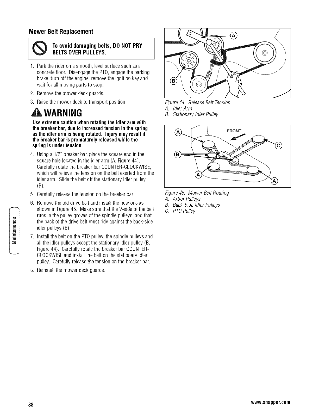
MowerBeltReplacement
Toavoiddamagingbelts, DONOTPRY
BELTSOVER PULLEYS.
1. Parkthe rider on a smooth, levelsurfacesuch asa
concrete floor. Disengagethe PTO,engagethe parking
brake,turn off the engine, removethe ignition key and
wait for all moving parts to stop.
2. Removethe mower deckguards.
3. Raisethe mower deckto transport position.
A WARNING
Useextremecautionwhen rotatingtheidler armwith
the breakerbar, duetoincreasedtensionin the spring
as theidler armis being rotated. Injurymay resultif
the breakerbar is prematurelyreleasedwhile the
springisundertension.
4. Using a 1/2" breakerbar,placethe squareend in the
square hole located in the idler arm (A, Figure44).
Carefullyrotatethe breakerbar COUNTER-CLOCKWISE,
which will relievethetension on the belt exerted from the
idler arm. Slide the belt off thestationary idler pulley
(B).
5. Carefullyreleasethe tension on the breakerbar.
6. Removethe old drive beltand install the new oneas
shown in Figure45. Makesurethat the V-side of the belt
runs in the pulley groves of the spindle pulleys,and that
the back of the drive belt must ride againstthe back-side
idler pulleys (B).
7. Installthe belt on the PTOpulley,the spindle pulleys and
all the idler pulleys exceptthe stationary idler pulley (B,
Figure44). Carefully rotatethe breakerbar COUNTER-
CLOCKWISEand install the belt on the stationary idler
pulley. Carefullyreleasethe tension on the breakerbar.
8. Reinstallthe mower deck guards.
Figure44, ReleaseBelt Tension
A. IdlerArm
B, Stationary Idler Pulley
¢...
Figure45. Mower BeltRouting
A, Arbor Pulleys
B, Back-SideIdler Pulleys
C. PTOPulley
38 www.snapper.com
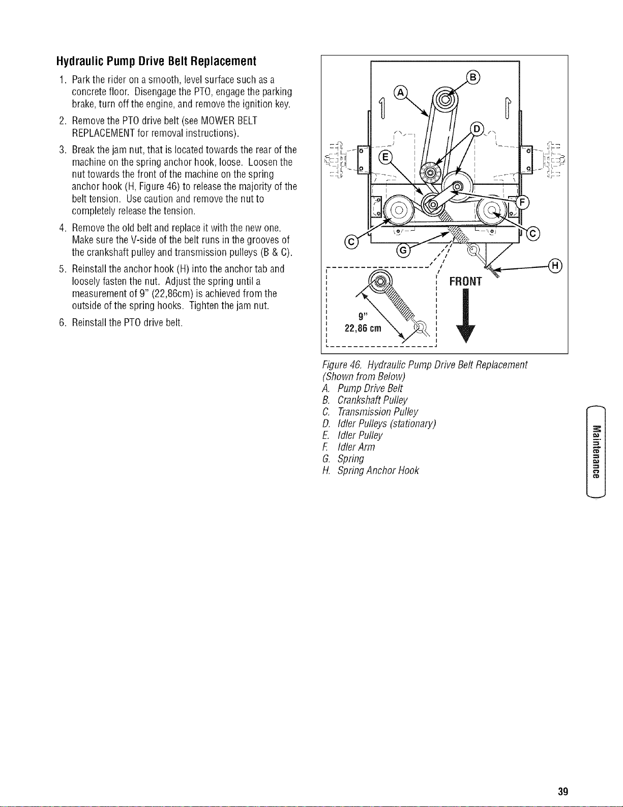
HydraulicPumpDriveBeltReplacement
1. Parkthe rider on a smooth, levelsurfacesuch asa
concrete floor. Disengagethe PTO,engagethe parking
brake,turn off the engine,and removethe ignition key.
2. Removethe PTOdrive belt (seeMOWERBELT
REPLACEMENTfor removalinstructions).
3. Breakthe jam nut, that is located towards the rear of the
machineon the spring anchor hook, loose. Loosenthe
nuttowards the front of the machineon the spring
anchor hook (H, Figure46) to releasethe majority of the
belttension. Usecaution and removethe nut to
completely releasethetension.
4. Removethe old beltand replaceit with the newone.
Makesurethe V-side of the belt runs in the grooves of
the crankshaft pulleyand transmission pulleys (B & C).
5. Reinstallthe anchor hook (H) into the anchor tab and
loosely fastenthe nut. Adjust the spring until a
measurementof 9" (22,86cm) is achievedfrom the
outside of the spring hooks. Tightenthe jam nut.
6. Reinstallthe PTOdrive belt.
Figure46, HydraulicPump Drive Belt Replacement
(Shownfrom Below)
A, Pump DHveBelt
B. CrankshaftPulley
C. TransmissionPulley
D. Idler Pulleys (stationary)
E. Idler Pulley
F. IdlerArm
G. Spring
H. Spring Anchor Hook
f_
¢"D
3g
Troubleshooting
While normal careand regular maintenancewill extend the
life of your equipment, prolonged or constant usemay
eventuallyrequire that service be performed to allow it to
continue operating properly.
Thetroubleshooting guide below lists the most common
problems, their causesand remedies.
Seethe information on the following pagesfor instructions
on how to perform most of these minor adjustments and
service repairsyourself. If you prefer,all of these procedures
can beperformed for you byyour localauthorized dealer.
, WARNING
Toavoidseriousinjury,performmaintenanceonthe
tractoror mower onlywhenthe engineisstoppedand
theparkingbrakeengaged.
Alwaysremovethe ignitionkey, disconnectthespark
plugwire andfastenit awayfromthe plugbefore
beginningthe maintenance,to preventaccidental
startingofthe engine.
€_
o
TROUBLESHOOTINGTHE RIDER
PROBLEM
Enginewillnotturnoverorstart.
CAUSE
1. Parking brake not engaged.
2. PTO(electric clutch) switch
in ONposition.
3. Ground Speed/ SteeringControl
Levers not in the NEUTRALposition.
4. Outof fuel.
5. Engineflooded.
6. Fuseblown.
7. Batteryterminals require
cleaning.
8. Batterydischarged or dead.
9. Wiring looseor broken.
10.
11.
12.
13.
14.
Enginestartshardorrunspoorly. 1.
2.
Engineknocks. 1.
2.
Excessiveoilconsumption. 1.
Engineexhaustisblack.
Solenoid or starter motor faulty.
Safetyinterlock switch
faulty.
Spark plug(s) faulty, fouled
or incorrectly gapped.
Waterin fuel.
Gasis old or stale.
Fuelmixture too rich.
Spark plug faulty, fouled, or
incorrectly gapped.
Low oil level.
Using wrong gradeoil.
Engine running too hot.
2. Usingwrongweightoil.
3. Toomuchoil in crankcase.
1. Dirtyairfilter.
2. Enginechokecontrol
isin closedposition.
REMEDY
1.Engageparkingbrake.
2.Placein OFFposition.
3.MoveGroundSpeed/ SteeringControlLevers
to theNEUTRALposition.
4.If engineishot,allowitto cool,thenrefill
thefueltank.
5.Movechokecontroltoclosedposition.
6.Replacefuse.
7.Cleanthebatteryterminals
8. Rechargeor replace.
9. Visually checkwiring & replace brokenor
frayed wires. Tightenloose connections.
10. Repairor replace. Seeauthorized dealer
11. Replaceasneeded.Seeauthorized
servicedealer.
12. Cleanandgap or replace.
Seeengine manual.
13. Drainfuel & replacewith fresh fuel.
14. Drainfuel & replacewith fresh fuel.
1. Cleanair filter. Checkchoke adjustment.
2. Cleanand gapor replace.
(Seeengine manual.)
1. Check/addoil asrequired.
2. Seeengine manual.
1. Cleanenginefins, blower screen and
air cleaner.
2. Seeengine manual.
3. Drain excess oil.
1. Replaceair filter. See engine manual.
2. Openchoke control.
40 www.snapper.com

Rider Troubleshooting Continued.
PROBLEM CAUSE REMEDY
Engine runs,but rider will 1. Hydraulic releaselever(s) 1. Move lever(s) forward to "drive" position.
notdrive, in "free-wheel" position. SeePushing The Rider ByHand.
2. Belt is broken. 2. SeeDrive Belt Replacement.
3. Drive belt slips. 3. Seeproblem and causebelow.
4. Brakeis notfully released. 4. Seeauthorized service dealer
Riderdrive bell slips. 1. Pulleys or belt greasyor oily. 1. Cleanas required.
2. Tensiontoo loose. 2. Adjust spring tension.
SeeDrive Belt Replacement
3. Belt stretched orworn. 3. Replacebelt.
Brakewill nothold. 1. Brakeis incorrectly adjusted. 1. SeeBrakeAdjustment.
2. Brakepadsworn. 2. Replacewith new brakepads.
Ridersteersorhandles poorly. 1. Steering linkage is loose. 1. Checkand tighten any loose connections.
2. Improper tire inflation. 2. SeeRegular MaintenanceSection.
TROUBLESHOOTINGTHE MOWER
PROBLEM CAUSE REMEDY
Mower will notraise. 1. Lift linkagenot properly attached 1. Seeauthorized service dealerfor repair.
or damaged.
Enginestallseasily with 1. Enginespeedtoo slow.
mowerengaged. 2. Ground speedtoo fast.
3. Cutting height settoo low.
Excessivemowervibration.
Excessivebeltwear or breakage.
Mower drive belt slips
orfails to drive.
Mower doesnotengage.
4. Discharge chutejamming
with cut grass.
1. Blademounting bolts areloose.
2. Mower blades,arbors,
or pulleys arebent.
3. Mower bladesareout
of balance.
4. Belt installed incorrectly.
1. Bentor rough pulleys.
2. Using incorrect belt.
1. Idler pulley spring broken or not
properly attached.
2. Mower drive belt broken.
1. Electricalwiring damage.
2. Batteryvoltage too low.
1. Setto full throttle.
2. DecreaseGroundSpeed.
3. Cuttall grass at maximum cutting
height during first pass.
4. Cutgrass with discharge pointing toward
previously cut area.
1. Tightento 70 ft.lbs. (94 Nm).
2. Checkand replaceas necessary.
3. Remove,sharpen, and balanceblades.
SeeMaintenance Section.
4. Reinstall Correctly.
1. Repairor replace.
2. Replacewith correct belt.
1. Repairor replace as needed.
2. Replacedrive belt.
1. Locate & repair damagedwire.
2. Rechargebattery and checkalternator.
SeeBattery Maintenancesection.
41
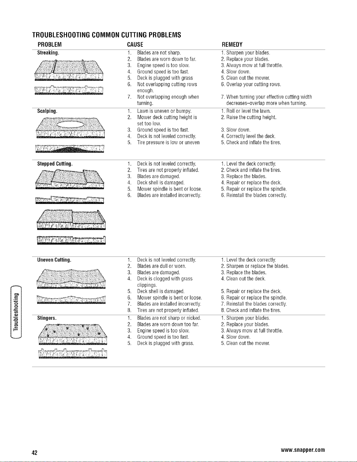
TROUBLESHOOTINGCOMMON CUTTING PROBLEMS
CAUSEPROBLEM
Streaking.
Scalping.
1. Bladesare not sharp.
2. Bladesareworn down to far.
3. Enginespeed istoo slow.
4. Ground speedis too fast.
5. Deck is plugged with grass
6. Not overlapping cutting rows
enough.
7. Not overlapping enoughwhen
turning.
1. Lawn is unevenor bumpy.
2. Mower deck cutting height is
settoo low.
3. Ground speedis too fast.
4. Deck is not leveledcorrectly.
5. Tire pressure is low or uneven
REMEDY
1.Sharpenyourblades.
2.Replaceyourblades,
3.Alwaysmowatfull throttle.
4.Slowdown.
5.Cleanoutthemower,
6.Overlapyourcuttingrows.
7. Whenturning your effectivecutting width
decreases-overlap more when turning.
1. Roll or levelthe lawn.
2. Raisethe cutting height.
3. Slow down.
4. Correctly levelthe deck.
5. Checkand inflatethe tires.
SteppedCutting. 1. Deck is not leveledcorrectly.
2. Tiresare not properly inflated.
3. Bladesaredamaged.
4. Deck shell is damaged.
5. Mower spindle is bentor loose.
6. Bladesareinstalled incorrectly.
1. Levelthe deckcorrectly.
2. Checkand inflatethe tires.
3. Replacethe blades.
4. Repairor replacethe deck.
5. Repairor replacethe spindle.
6. Reinstallthe bladescorrectly.
fl#
o
#,
UnevenCutting.
Stingers.
1. Deck is not leveledcorrectly.
2. Bladesaredull or worn.
3. Bladesaredamaged.
4. Deck is clogged with grass
clippings.
5. Deck shell is damaged.
6. Mower spindle is bentor loose.
7. Bladesareinstalled incorrectly.
8. Tiresare not properly inflated.
1. Bladesare not sharp or nicked.
2. Bladesareworn down too fan
3. Enginespeed istoo slow.
4. Ground speedis too fast.
5. Deck is plugged with grass.
1. Levelthe deck correctly.
2. Sharpen or replacethe blades.
3. Replacethe blades.
4. Cleanout the deck.
5. Repairor replacethe deck.
6. Repairor replacethe spindle.
7. Reinstallthe bladescorrectly.
8. Checkand inflatethe tires.
1. Sharpenyour blades.
2. Replaceyour blades.
3. Always mow atfull throttle.
4. Slow down.
5. Cleanout the mower.
42 www.snapper.com

Specifications
Product Specifications
DeckSize(inches)
HeightofCut(inches)
TransaxleType
GroundSpeed- Fwd/Rev(mph)
EnginePower(hp)
EngineDisplacement(cc)
FuelTankCapacity(gal)
355ZB2654
54"
1.5"-4.5"
HydroGearZT2800
0-7/0-5
26.0*
570
6.5
*Engine PowerRating information
Thegross power rating for individual gasengine models is labeled in accordancewith SAE(Societyof Automotive Engineers)
codeJ1940 (Small EnginePower& TorqueRating Procedure),and rating performance hasbeenobtainedand corrected in
accordancewith SAEJ1995 (Revision 2002-05). Torquevaluesare derivedat 3060 RPM;horsepower valuesare derivedat
3600 RPM.Actual gross engine power will be lower and is affected by,among other things, ambient operating conditions and
engine-to-enginevariability. Givenboth the wide arrayof products on which enginesare placedand the varietyof
environmental issuesapplicableto operatingthe equipment, the gasengine will not developthe ratedgross power when used
in a givenpieceof powerequipment (actual"on-site" or net power). This differenceis due to avariety of factors including, but
not limited to, accessories(air cleaner,exhaust, charging, cooling, carburetor,fuel pump, etc.), application limitations, ambient
operating conditions (temperature,humidity, altitude), and engine-to-enginevariability. Dueto manufacturing and capacity
limitations, Briggs & Stratton maysubstitute an engine of higher ratedpowerfor this Seriesengine.
o
43
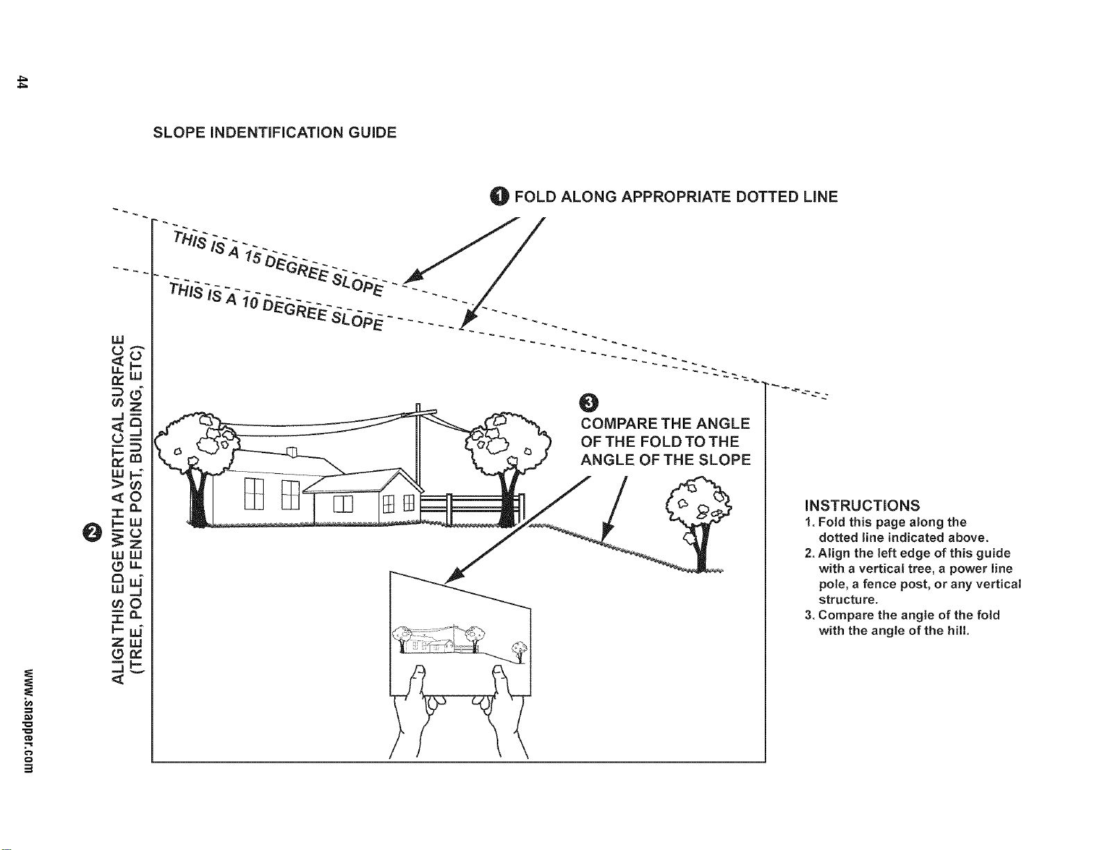
SLOPE INDENTIFICATION GUIDE
O
co
.=_
o
uJ
L)
Lu
,_O
.,r,.Q-
wuJ
LOLL
a
cnO
zuJ
Lg_
FOLD ALONG APPROPRIATE DOTTED LiNE
0
COMPARE THE ANGLE
OF THE FOLD TO THE
ANGLE OF THE SLOPE
INSTRUCTIONS
1. Fold this page along the
dotted line indicated above.
2. Align the left edge of this guide
with a vertical tree, a power line
pole, a fence post, or any vertical
structure.
3. Compare the angle of the fold
with the angle of the hill.
2 YEAR LIMITED WARRANTY
®
Fortwo (2) years from purchasedatefor the original purchaser'sresidential,non-commercial use, SNAPPER,through any
authorizedSNAPPERdealerwill replace,free of charge (exceptfor taxeswhere applicable),any part or parts found upon
examinationbythe factory at McDonough, Georgia,to be defectivein material or workmanship or both.
Forninety (90) days from purchasedatefor the original purchaser'scommercial, rental,or other non-residential use,
SNAPPER,through any authorizedSNAPPERdealerwill replace,free of charge,any part or parts found upon examinationby
thefactory at McDonough, Georgia,to be defective in material or workmanship or both.
All transportation costs incurred bythe purchaserin submitting materialto an authorized SNAPPERdealer for replacement
underthis warranty must be paid by the purchaser.
This warranty doesnot applyto certain transmissions, to enginesandtheir components, and batteries, asthese items are
warrantedseparately. This warranty does not applyto parts that havebeendamagedbyaccident, alteration, abuse,improper
lubrication, normal wear, or other cause beyondthe control of SNAPPER.This warranty doesnot cover any machine or
componentpart that hasbeen alteredor modified changing safety,performance, or durability.
Batterieshavea one (1) yearwarranty period with free replacementif required for one (1) year from the original purchasedate.
SNAPPERwill not be responsiblefor any installationcost incurred. The batterywarranty onlycovers original equipment
batteriesand doesnot cover damageto the battery or machine causedby neglect or abuse, destruction byfire, explosion,
freezing,overcharging,improper maintenance,or useof improper electrolyte.
Thereis no other expresswarranty.
DISCLAIMEROFWARRANTY
Implied warranties,includingthoseof merchantabilityandfitness for a particularpurpose,are limited totwo(2) years
frompurchase dateforthe original purchaser's residentialor other non-commercialuse, andninety(90) daysfrom
purchase forthe original purchaser'scommercial, rental or othernon-residentialuse, andtothe extentpermittedby law,
anyand all impliedwarranties areexcluded.This isthe exclusiveremedy.Liabilitiesfor consequentialdamages,under
anyandall warranties are excluded.
Somestatesdo notallow limitations on howlongan impliedwarrantylasts, or donotallow theexclusionor limitation of
incidentalor consequentialdamages,sothe abovelimitation or exclusionmaynotapplytoyou.
This warrantygives you specific legal rights, and you mayalso haveother rights which vary from stateto state.
WARNING:THEUSEOFREPLACEMENTPARTSOTHERTHANGENUINESNAPPERPARTSMAYIMPAIRTHESAFETYOF
SNAPPERPRODUCTSANDWILL VOIDANYLIABILITYANDWARRANTYBY SNAPPERASSOCIATEDWITHTHEUSEOFSUCH
PARTS.
IMPORTANT:
Pleasefill outthe attachedSNAPPERProduct Registration Cardimmediately and mail to:
Snapper'sProductRegistrationCenter, P.O.Box1379, McDonough,Georgia30253
45

EnginePowerRatingInformation: Thegross power rating for individual gasengine models is labeledin accordancewith SAE
(Societyof Automotive Engineers)code J1940 (Small EnginePower & Torque Rating Procedure),and ratingperformance has
beenobtainedand corrected in accordancewith SAEJ1995 (Revision 2002-05). Torquevalues are derivedat 3060 RPM;
horsepowervalues are derivedat 3600 RPM.Actual gross engine power will be lower and is affected by,among other things,
ambient operatingconditions and engine-to-enginevariability. Givenboth the widearray of products on which enginesare
placedand the variety of environmental issuesapplicableto operatingthe equipment,the gasengine will not developthe rated
gross power when usedin a givenpiece of powerequipment (actual "on-site"ornet power). Thisdifferenceis dueto a variety
offactors including, but not limited to, accessories(air cleaner,exhaust,charging, cooling, carburetor,fuel pump, etc.),
application limitations, ambient operatingconditions (temperature, humidity, altitude), and engine-to-enginevariability. Dueto
manufacturing and capacity limitations, Briggs & Stratton maysubstitute anengine of higher rated powerfor this Series
engine.
SM, 2P£R
Models and spedfications are subject to change without notice.
BR|GGS_S.STRATTON YARD POWER PRODUCTS GROUP
MILWAUKEE, WI 53201 USA
www, snapper, corn @2008 Briggs & Stratton Power Products Group, LLC