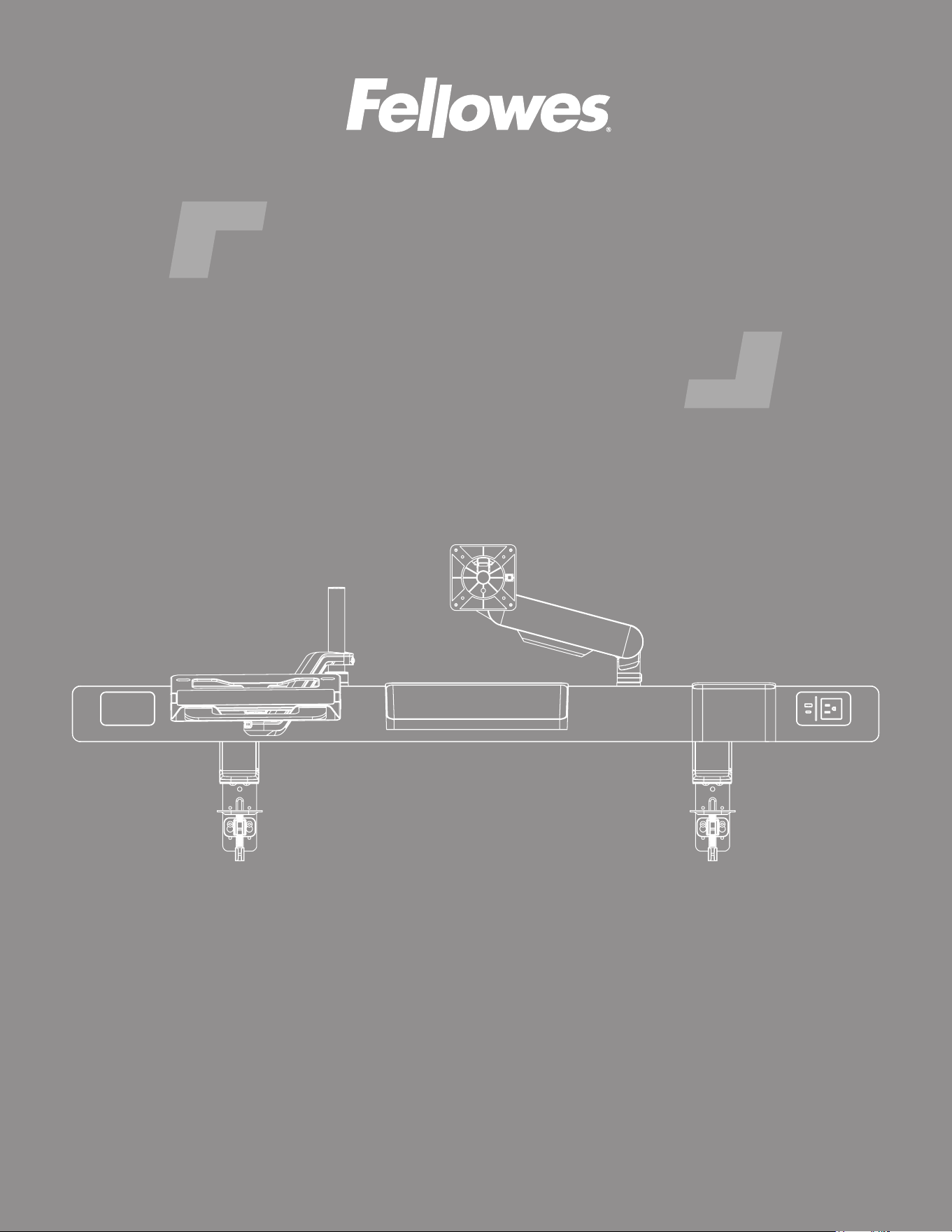
Rising Loft
™
INSTALLATION INSTRUCTIONS
IMPORTANT SAFETY INSTRUCTIONS AND WARNINGS
Read before using!
Page 2
• Read and follow all instructions and warnings before use. Save these instructions for future reference.
• Use this product only in the manner intended by the manufacturer. If you have questions, contact the
manufacturer.
• This product contains small items that could be a choking hazard if swallowed. Keep away from children.
• Make sure the desk or mounting surface can support the combined weight of the rail and its attachments with
accessories.
• Make sure the installation location is free of obstructions and will have plenty of clearance.
• Do not extend monitors behind the base.
• Never exceed the maximum load capacity stated for this product. Serious injury or property damage may
occur.
• Minimum load capacity must be reached for the monitor arms.
• Hand tighten screws only. Do not use power tools.
• When connecting and routing monitor cables and power cords, make sure the cables and cords are long
enough to accommodate the full range of motion.
• Do not touch the power cord with wet hands. It may result in electrical shock.
• Do not use if the power cord or plug is damaged.
• Do not connect this product to any electrical outlet that is damaged.
• Do not bend the power cord excessively or place heavy objects on top of it.
• Do not alter the length of the power cord.
• Do not use extension cords, adapters, or power strips with this product.
• Unplug product before moving or reconguring.
• This product is only compatible with Fellowes Rising accessories.
• This product is for indoor use only.
Rising Loft Components and tools
Page 3
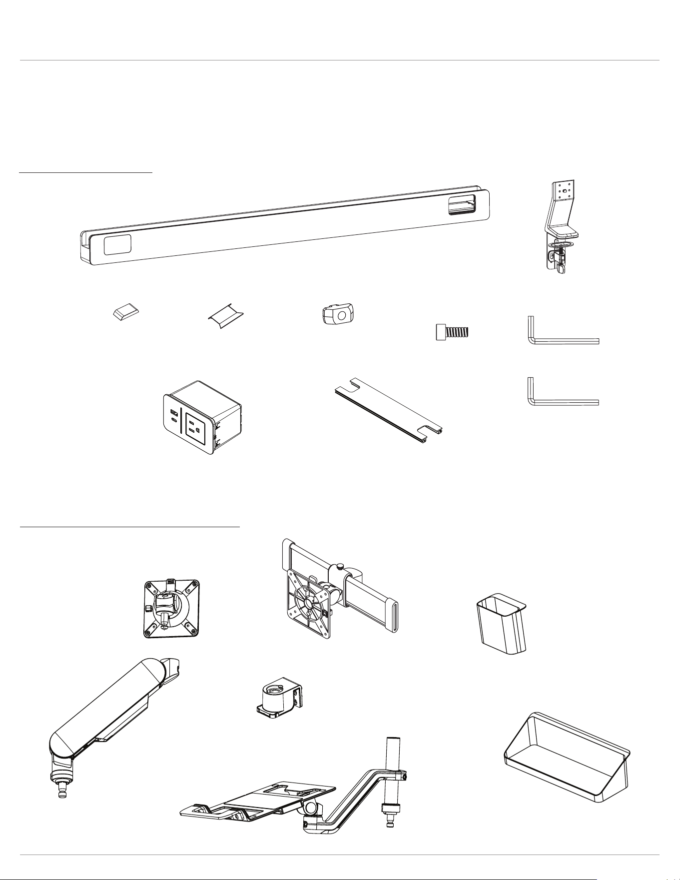
Please review these instructions before beginning the installation. Check that all the components needed for installation
were provided with your order. Contact your supplier if any parts are missing. Do not discard the packaging until the product
works to your satisfaction.
Components and tools
Optional accessories (sold separately)
slider mount
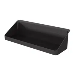
utility cup
rail adapter
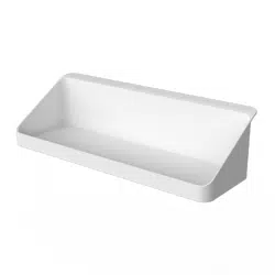
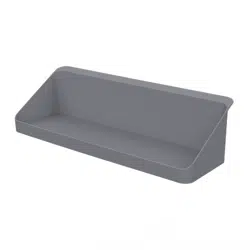
shelf
laptop holder
Rising™ monitor arm
60” rail x4
48” rail x3
24” rail x1
x2
x1
x1
x4
x2
x8
x8
M5x12
x1
4mm
5mm
Rising Loft Installation
Page 4
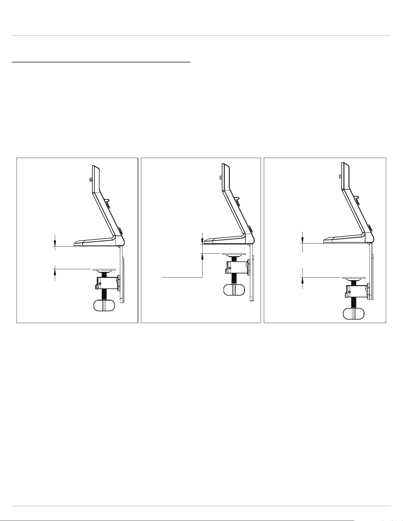
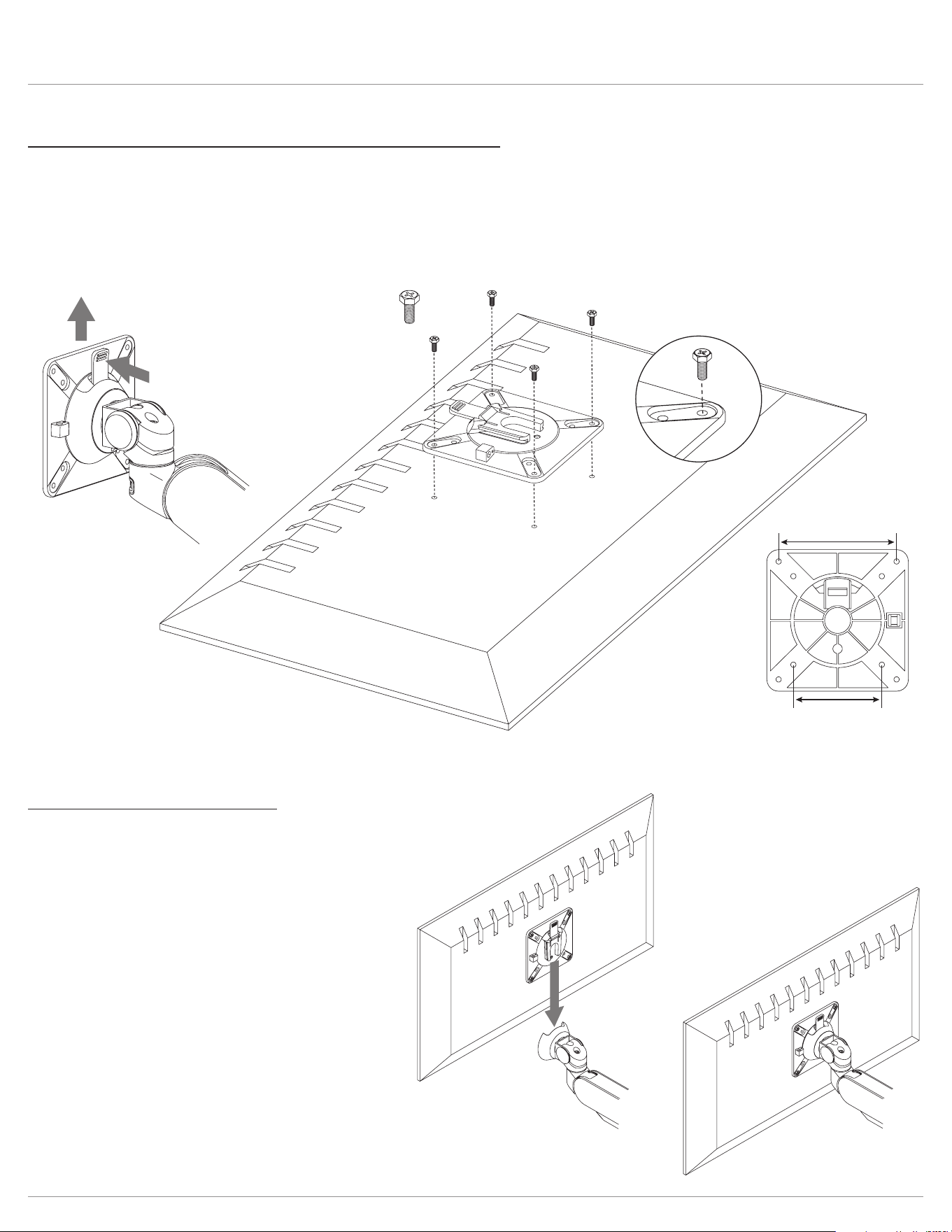
Step #1: attach clamp assembly to bracket on base.
If not using the standard attachment position, attach the clamp assembly to screws in the desired location.
• Slide the large portion of the keyhole over the screws, then pull the clamp assembly down so that the narrow portion can
be secured when tightening the screws.
• Loosen the screws with the 4mm Allen key if necessary to t the narrow portion over them.
• Tighten the screws with the 4mm Allen key.
1.89" - 3.23"
(48 - 82 mm)
Lower Attachment
Position (Optional)
Standard
Higher Attachment
Position (Optional)
0"- 1.10"
(0 - 28 mm)
1.06" - 2.21"
(27- 56.13 mm)
Page 5
Rising Loft Installation
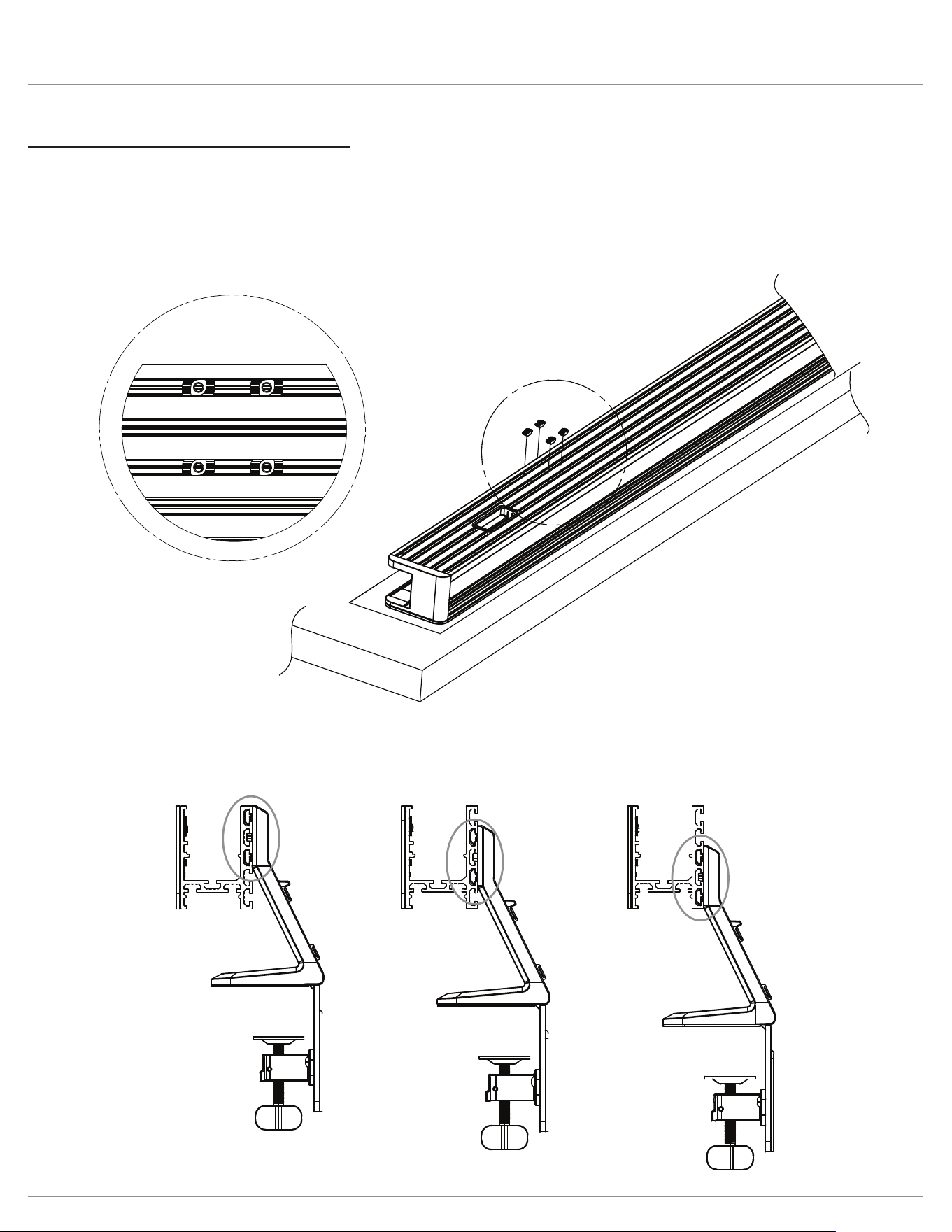
Step #2: prepare rail for base assembly
Place rail glass side down on table. Ensure to use a piece of corrugated paper or cloth as a barrier to protect the glass
surface.
• Install (4) t-nuts to backside of rail. There are (3) possible height positions. Option 1 will sit lowest to the worksurface, while
option 3 will sit highest o the worksurface. Repeat on other side of rail.
option 1 option 2 option 3
Rising Loft Installation
Page 6
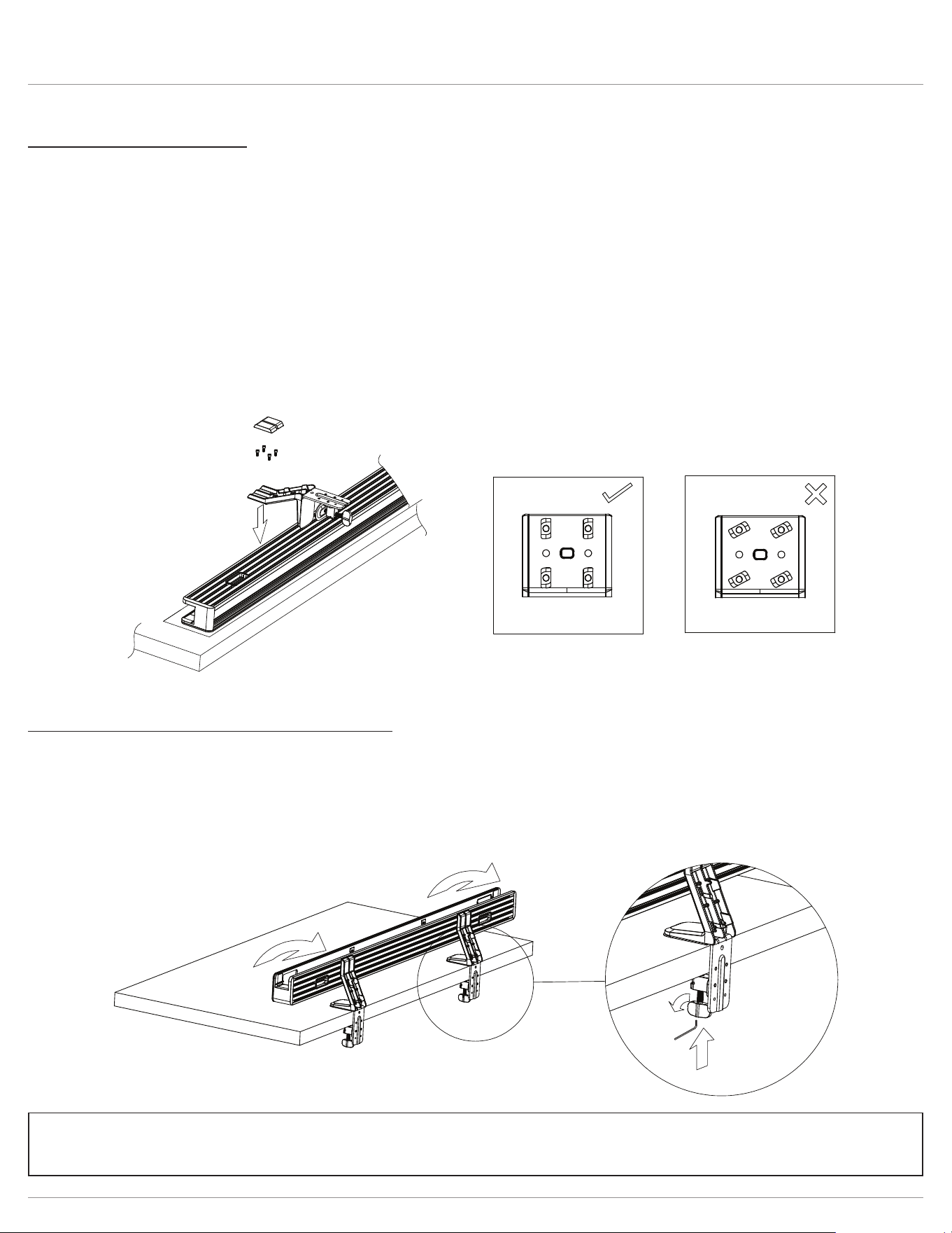
Step #3: attach base to rail
• Attach base to t-nuts installed in previous step using provided (4) M5 screws and 4mm Allen key.
• (Optional) Pre-install screws and t-nuts to the base and do not fully tighten. Ensure t-nuts are horizontal and place into
desired slots on the rail.
• The edge of the clamp should be positioned 10.6” from each end of the 60” and 48” rails. For the 24” rail, they should be
positioned 3” from each end. While the screws are still loosened in the t-nut, adjust the distance from the edge for ease
of use.
• Ensure screws are securely tightened and t-nuts turn into vertical position when tightening. See correct and incorrect
images below.
• Place covers over screws.
• Repeat for other base.
• (Optional) If using 3 monitors totaling over 60lbs, a third base will be required (sold separately). The third base should be
installed in the center of the rail.
Step #4: attach rail assembly to worksurface
• Carefully rotate the assembly onto the edge of the desk.
• When in the desired position, push the clamp knob upwards until it touches the desk.
• Turn the knob until tight.
• The 5mm Allen key ts into the bottom of the clamp knob and may be used to further tighten the clamp, if necessary.
• Repeat steps with other clamp.
Please refer to the separate Power Module Manual for additional information
and optional installation instructions.
Rising Loft Optional accessories
Page 7
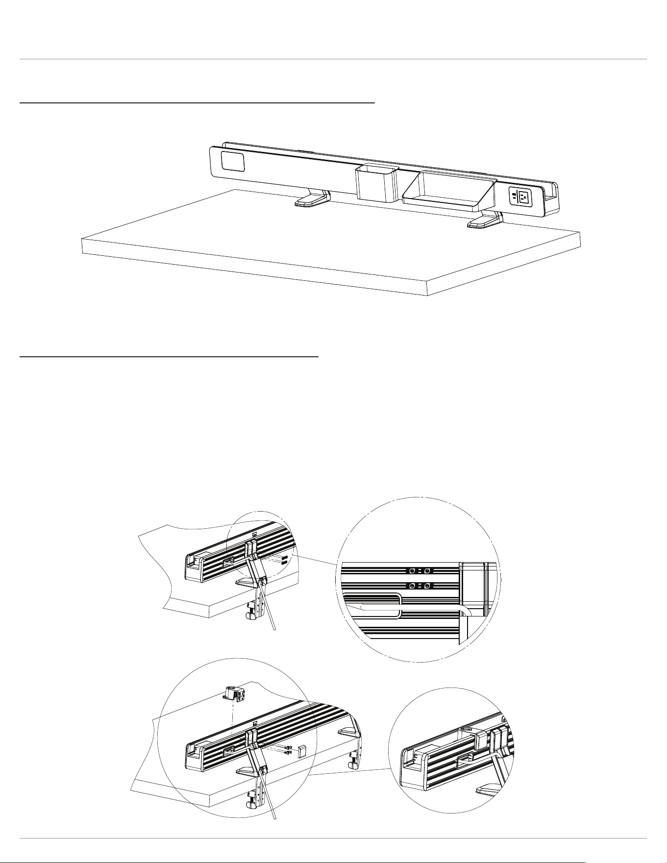
Step #5: optional accessories: utility cup and shelf installation
• Hook the utility cup and or shelf onto the front edge of the rail, a magnet will hold securely in place.
Step #6: optional accessory: rail adapter installation
The rail adapter needs to be installed rst to install the monitor arm or laptop holder accessories.
• Install four t-nuts to the rear of the rail within the top two slots (two in each slot).
• Place the rail adapter on the rail in the location the t-nuts were installed. Slide it along the rail and position
as needed.
• If a heavy monitor will be installed, the system will be most stable when closest to a base leg.
• Ensure the rail adapter is aligned with the t-nuts and install four M5 screws using the 3mm Allen Key. Ensure screws are
securely tightened.
• Place cover on the backside over the screws.
Rising Loft Optional accessories
Page 8
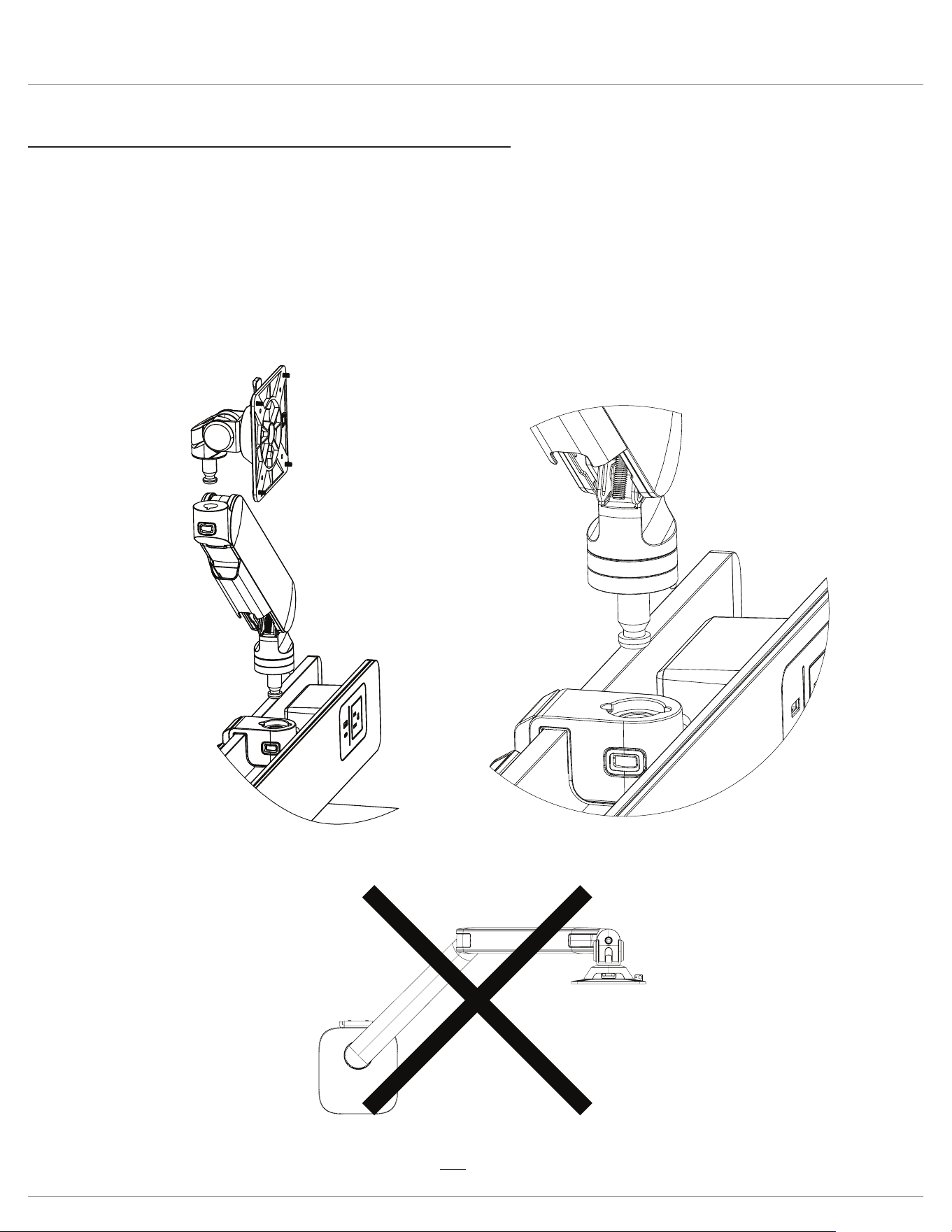
Step #7: optional accessory: monitor arm installation to rail
The rail adapter feature allows you to simply push the posts on the components into the openings until they snap securely
into place.
• Ensure the notch on both the monitor arm and rail adapter are aligned to allow the arm to sit ush and snap securely
into place.
• Attach the VESA mount or slider mount to the monitor arm (see Step 11 for additional slider mount instructions).
• Rail adapter quick release: To remove an installed monitor arm or VESA mount, press and hold the rail adapter quick
release button and lift up the component.
• Set the range of arm rotation using the RotationStop™ feature.
CAUTION: Monitors must not be positioned behind the base.
Rising Loft Optional accessories
Page 9
Step #7A: set range of motion for monitor arms
• Set the range of rotation using the RotationStop, which is located at the bottom of each individual monitor arm.
— The RotationStop consists of two rings. The rings rotate independently.
— Setpoints are indicated by the protrusions on each ring.
— Monitor arms will only be able to rotate between the points set by the top and bottom rings.
• Setpoints may be repositioned at any time by the user.
• For no restrictions on monitor arm rotation, align the setpoints on the top and bottom rings.
CAUTION: Monitors must not be positioned behind the base.
rotate top and bottom rings
to adjust range of motion
90º
example
90º
setpoints
180º
example
180º
setpoints
120º
example
120º
setpoints
360º
example
360º
setpoints aligned
rotate top and bottom rings
to adjust range of motion
90º
example
90º
setpoints
180º
example
180º
setpoints
120º
example
120º
setpoints
360º
example
360º
setpoints aligned
rotate top and bottom rings
to adjust range of motion
90º
example
90º
setpoints
180º
example
180º
setpoints
120º
example
120º
setpoints
360º
example
360º
setpoints aligned
Rising Loft Optional accessories
Page 10
Step #8: optional accessory: attach VESA plate to monitor
• Remove the VESA plate from the VESA mount by pushing on the tab and lifting the plate.
• Place the monitor face down on a at surface. Align the VESA plate holes with the holes on the back of the monitor.
— There are two sets of four holes on the VESA plate. One set has holes 3.9” (100mm) apart, the other set has holes 3”
(75mm) apart. Use the set that matches the holes on the monitor.
• Attach the VESA plate using the VESA plate screws. Use a Phillips screwdriver to install the screws.
Attach monitor to VESA mount
• Slide the VESA plate (with monitor attached) onto the VESA mount.
— Push down until the VESA plate clicks securely in place.
press tab
to release
attach
VESA plate
lift off
VESA plate
M4x10 Phillips
3.9"
(100mm)
3"
(75mm)
push down until
VESA plate clicks
into place
Rising Loft Optional accessories
Page 11
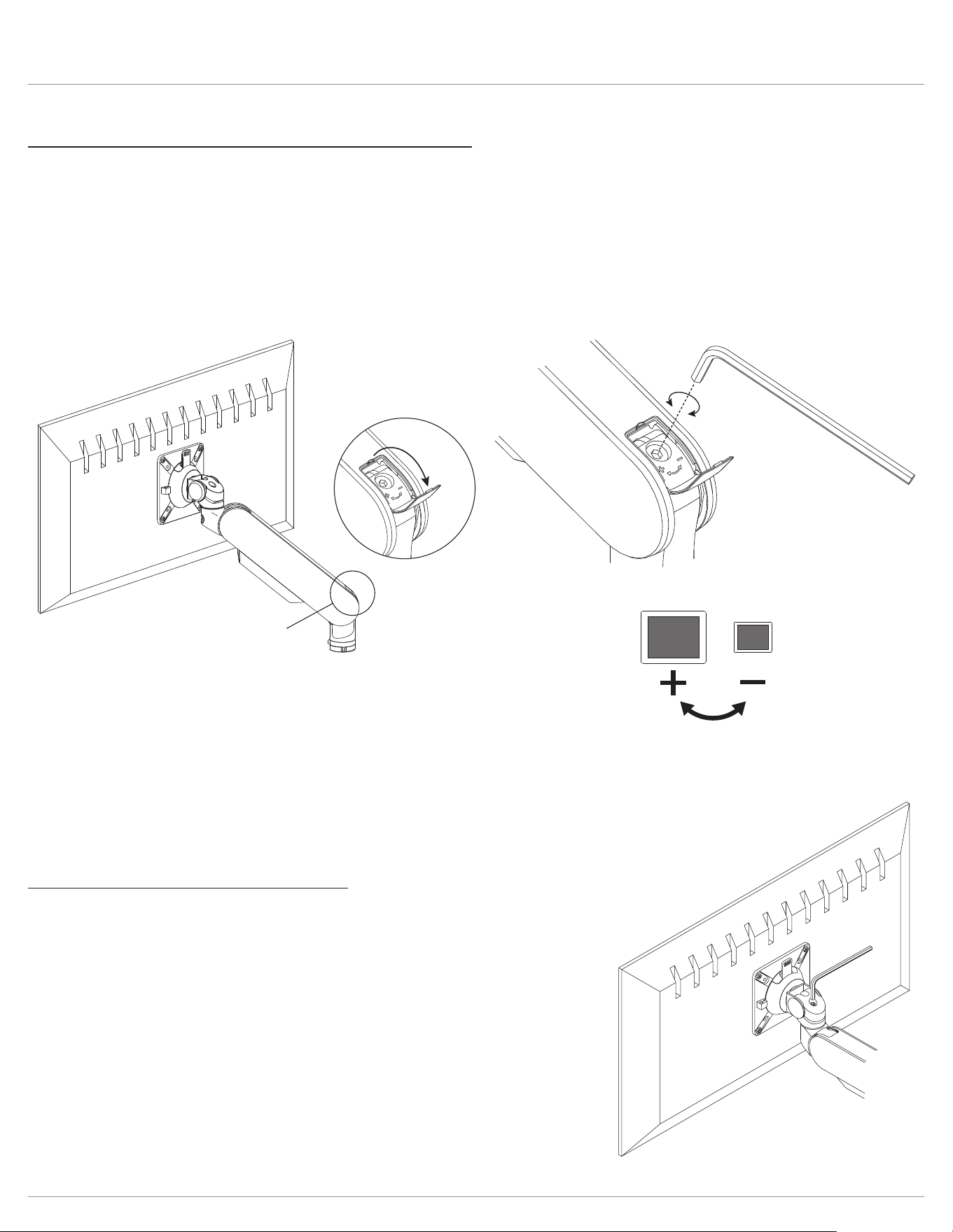
Step #9: optional accessory: monitor arm adjustments
The motion arm should raise and lower with moderate force, and then hold its position. To adjust for monitor weight:
• Flip up the tension-adjustment cover at the lower end of the motion arm to access the adjustment screw.
• Use the 5mm Allen key to loosen or tighten the socket screw.
— To increase the weight resistance of the motion arm (larger, heavier monitors), tighten the screw by turning it clockwise.
— To reduce the weight resistance of the motion arm (smaller, lighter monitors), loosen the screw by turning it
counterclockwise.
Adjust monitor tilt tension, if necessary
The monitor should tilt with moderate force and hold its position.
To adjust monitor tilt tension:
• Use the 5mm Allen key to loosen or tighten the socket screw on top of the
VESA mount.
— To increase the tension, tighten the screw by turning it clockwise.
— To reduce the tension, loosen the screw by turning it counterclockwise.
5mm
Allen key
rotate screw
to adjust tension
5mm Allen key
clockwise for
heavier weight
counterclockwise
for lighter weight
open
tension-adjustment
cover at lower end
of motion arm
Rising Loft Optional accessories
Page 12
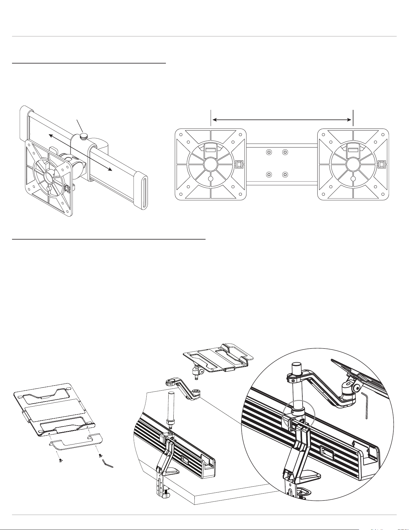
Step #10: optional accessory: slider mounts
• To move the monitor from side-to-side, rst loosen the knob screw on top of the slider mount.
• Slide the monitor along the slider bar.
— Re-tighten the set screw when the monitor is positioned where desired.
adjustability range:
8.9" (226mm)
loosen knob screw
to adjust
4mm allen key
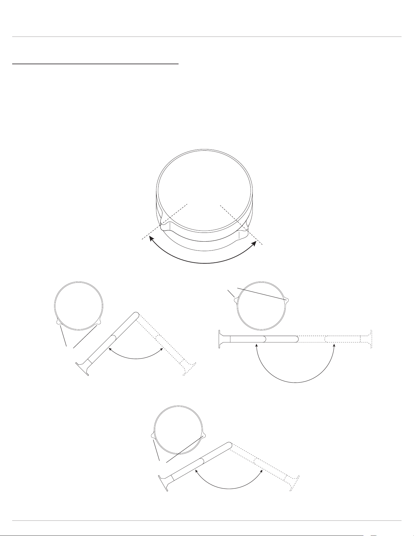
Step #11: optional accessory: laptop holder installation
• Attach the pole to the rail adapter. The small hole at the bottom of the pole must be facing the rear of the rail. Ensure the
notch on both the pole and rail adapter are aligned to allow the pole to sit ush and snap securely into place.
• Turn the pole fully to either the left or right until it stops.
• Slide the arm onto the pole and turn in the same direction the pole was turned until approximately ¼” away from the glass.
• Secure the xed arm to the pole by tightening the bolt with 5mm Allen key.
• Following the steps above will ensure the 80
º
range of motion is reached without hitting the glass.
• Install laptop holder handle using included two screws and 4mm Allen key.
• Attach the laptop holder to the xed arm.
• (Optional) Adjust the tilt function by turning the bolt on the side of the laptop holder knuckle using 6mm Allen key. Turn
clockwise for heavier devices and counter clockwise for lighter devices.
6mm allen key
Rising Loft Cable management
Page 13
Cable management
There are multiple forms of cable management within the Rising Loft system which will vary depending on the accessories
used.
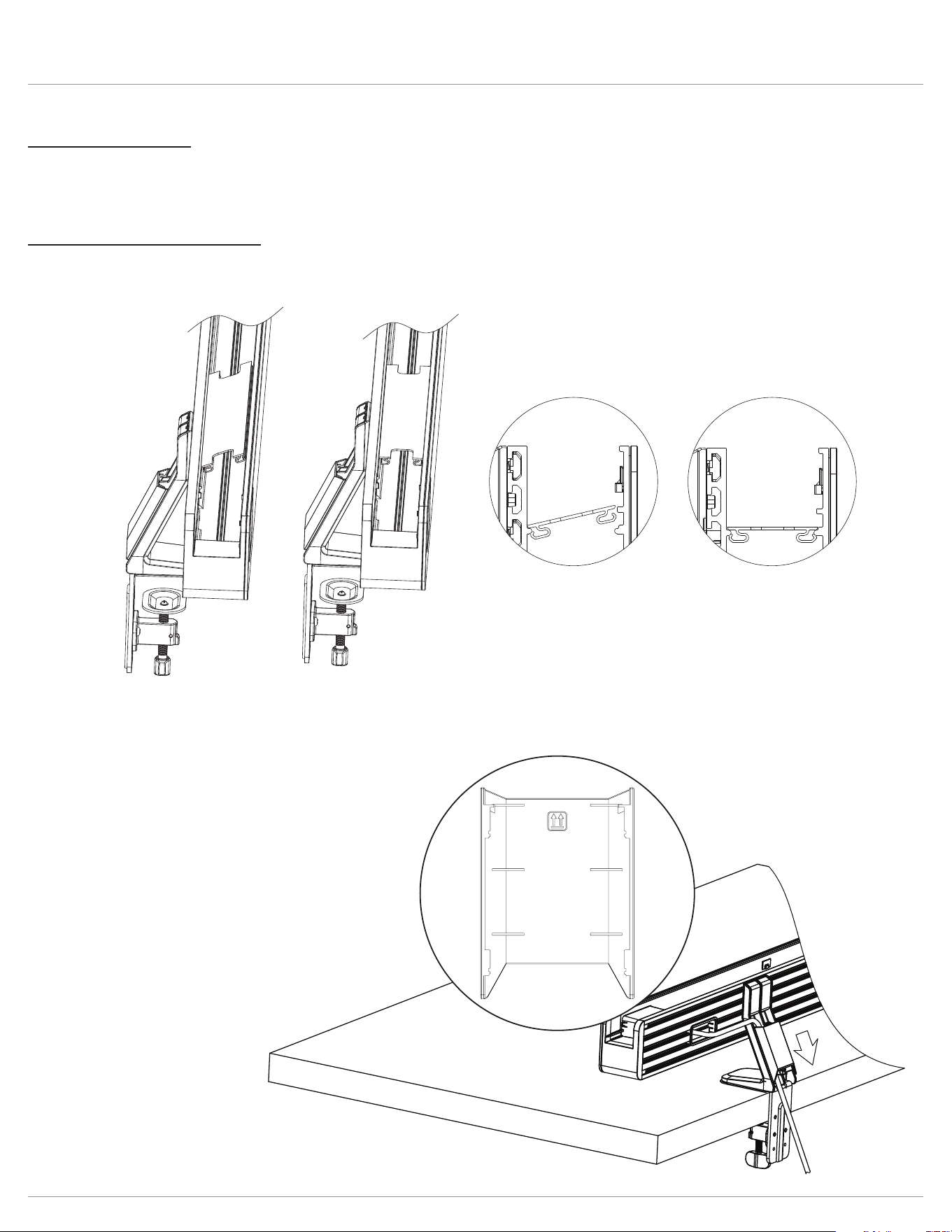
Interior Rail and Clamp Base
• Cables can be routed through the interior rail and out the back. Install cable covers by angling into the rear side rst, then
pressing down on the front side.
Top
Gather cables from the rear of rail and route down the rear of base clamp. Included base clamp cable cover attaches by
sliding down from the top until a click is heard.
• To remove, hold the rear of the cover and slide upward.
Rising Loft Cable management
Page 14
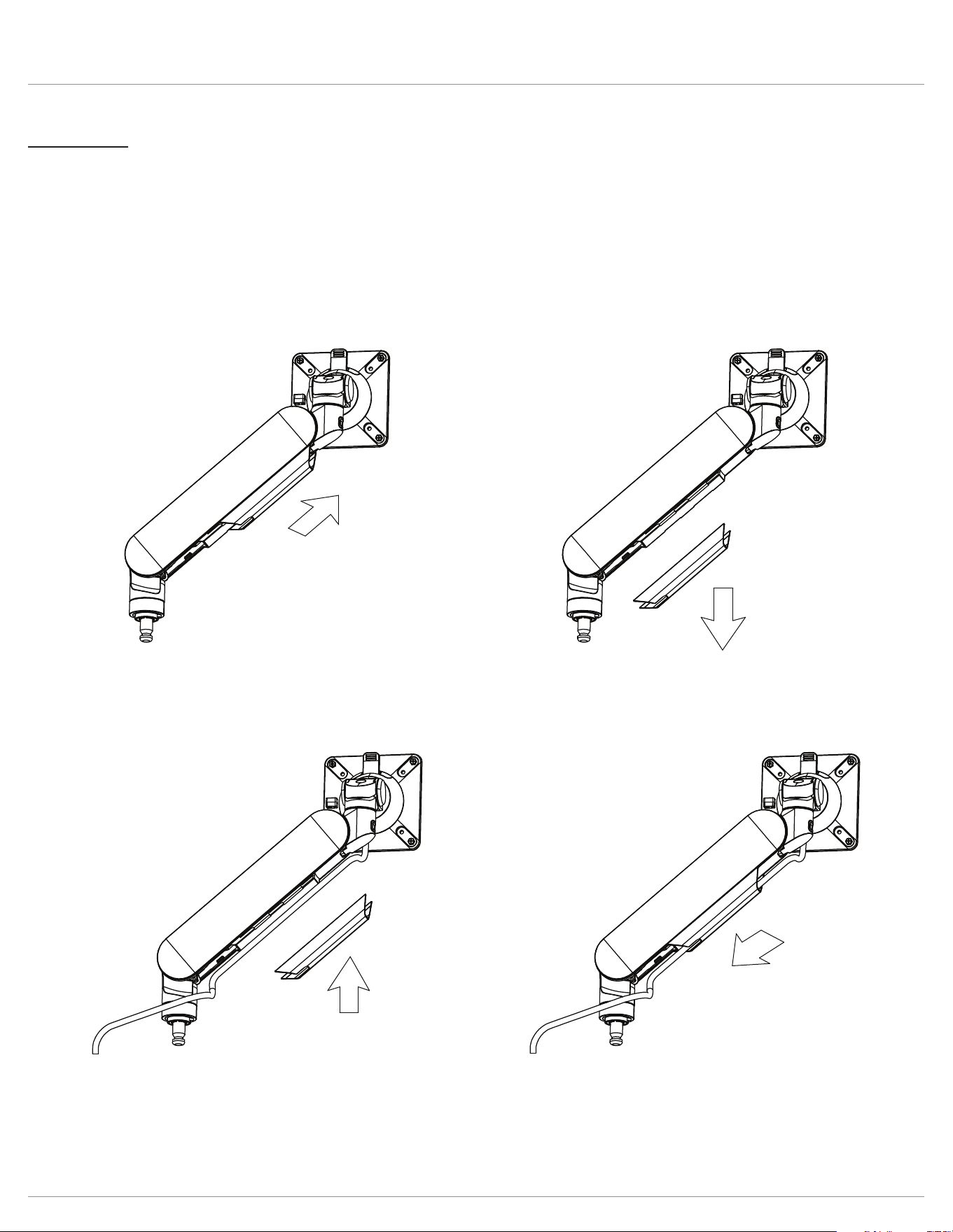
Monitor arm
• Remove the cable cover from the arm.
— Slide the cover forward and pull downward.
• Arrange the cables inside the cover.
• Slide the cover back onto the monitor arm with the cables captured.
IMPORTANT: After connecting the cables, check that the cables are long enough to accommodate the full range of motion
of the monitor arm.
Rising Loft Cable management
Page 15
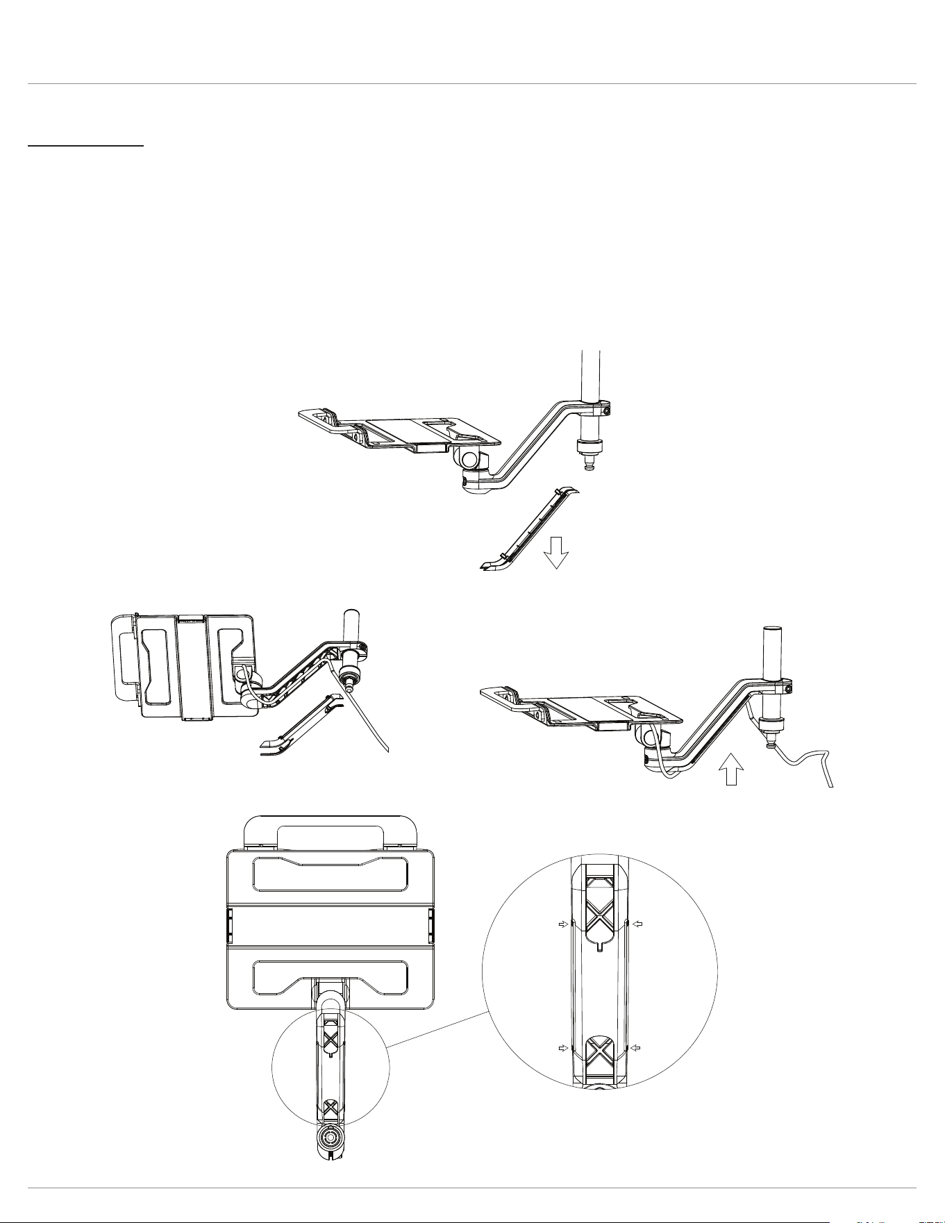
Laptop holder
• Remove the cable cover from the xed arm.
• Use the snap features on the cover. There are 4 pill shape cavities that show where the snaps are located. Press and ex
the top snaps rst, followed by the bottom snaps to remove.
• Arrange the cables inside the cover.
• Snap the cover back onto the xed arm with the cables captured.
IMPORTANT: After connecting the cables, check that the cables are long enough to accommodate the full range of motion
of the laptop holder.

© 2023 Fellowes, Inc. | Part #412868 Rev F
To contact a Fellowes
®
service representative, call 1-800-833-3746
Warranty information can be found by contacting customer service, your sales representative or by visiting www.fellowes.com