Loading ...
6"
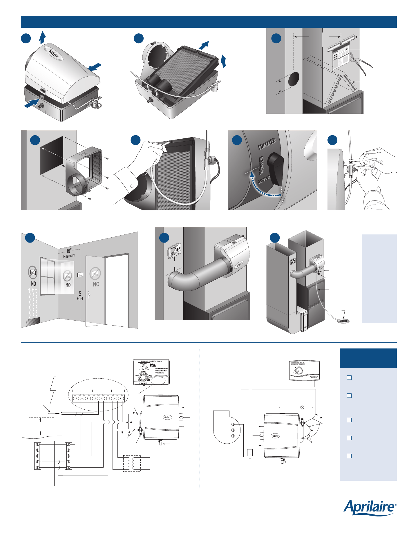
Template
Level
Do not position
opening in
front of
cooling coils.
Minimize
Distance
6"
Floor Drain or
Condensate
Pump
Drain Spud
Hose Clamp
Overflow Tube
Tighten water line by double wrenching.
Locate manual or digital humidifier control on the
return 6" above the humidifier or bypass duct.
Completed
Installation
Location of manual humidifier control in living space.
Insert feed tube into distribution tray.Secure base with screws.
Press tabs to
remove cover.
Pull feed tube out of
distribution tray, and remove
Water Panel® evaporative assembly. Cut opening using this template.
Overflow Tube:
• Ensure
downward
slope and
no kinks.
• Do not over-
tighten hose
clamp onto
drain spud.
• Do not use
solvent
adhesive on
drain spud.
INSTALLATION INSTRUCTIONS
Turn damper handle to WINTER when in use.
COMMON
HI
LO
Furnace
Blower Motor
Model 50 Current
Sensing Relay (if required)
24 VAC Furnace
Accessory Terminals
or Transformer
(10VA Minimum)
Shut-o
(Saddle Valve)
Water Supply
Yellow
Wires
White
Wires
Connect Overflow
Tube Here
G
Y
W
C
R
R
C
W
Y
G
OUTPUTSINPUTSPOWER
GW
CR H HODT GfA B
Yellow
Wires
White
Wires
Thermostat or
Zone Panel
Equipment Terminals
110 VAC
Furnace
Outdoor
Temperature
Sensor for
Automatic Mode
North, East
or West Side
of Home
Above Expected
Snow Line
Continuously Powered
24 VAC Transformer
Provided with Humidifier
Water
Supply
Connect
Overflow
Tube Here
ADHC Terminal Strip
IMPORTANT: Use 120 VAC power source
other than furnace motor circuit. However, the
transformer can be powered off the hot 120 VAC
line before it enters the furnace. Do not wire
transformer into furnace blower circuit.
IMPORTANT: When Model 50 current sensing relay is used, wire Model 50
current sensing relay into 24 VAC humidifier control circuit only! Do not install
in transformer primary circuit.
INSTALLATION
CHECKLIST
Saddle valve is
fully open.
All plumbing
connections are
watertight.
Humidifier
functions properly.
Bypass damper is
in proper position.
Owner’s manual
has been given to
homeowner.
NOTE: Control will display software revision level i.e. r1, when the
one minute test cycle has completed. Refer to the control installation
manual for system checkout instructions.
MODEL 400 DIGITAL HUMIDIFIER CONTROL WIRING MODEL 400M MANUAL CONTROL WIRING
90-1513
90-1399
TEMPLATE MUST BE LEVEL
P.O. Box 1467
Madison, WI 53701-1467
800.334.6011 F: 608.257.4357
AprilairePartners.com
Printed in USA
©2019 Aprilaire – Division of Research Products Corporation
10008973 B2205115F 1.19
8a
8b
9
6
7
1
4
5
2
3
90-2248
90-2248
90-1666
90-2248
90-1165
90-2248
90-2248
90-1068 90-2248
90-1069