Loading ...
Loading ...
Loading ...
Rinnai 7 EHPA_VMA Series 2 Heat Pump OIM
OPERATION PRINCIPLE
The operation of an electric heat pump is very similar to a refrigerator, but in reverse. A heat pump operates by
transferring heat from the ambient outside air into the water. Electricity is just used to operate the system, but not
to directly heat the water. Because of this energy consumption is signicantly reduced as compared to an electric
element hot water system. The warmer the climate in which the heat pump is installed, the more efcient the heat
pump system will be at heating water.
The heat pump unit includes a circulation pump which draws water from the bottom of the storage tank and returns
it to the tank at a higher temperature. A temperature sensor in the tank is used to control the heat pump operation
to achieve suitable tank temperatures.
During the occasional times when the ambient weather conditions aren’t suitable for the heat pump to operate, the
electric element will provide heating to ensure a supply of hot water.
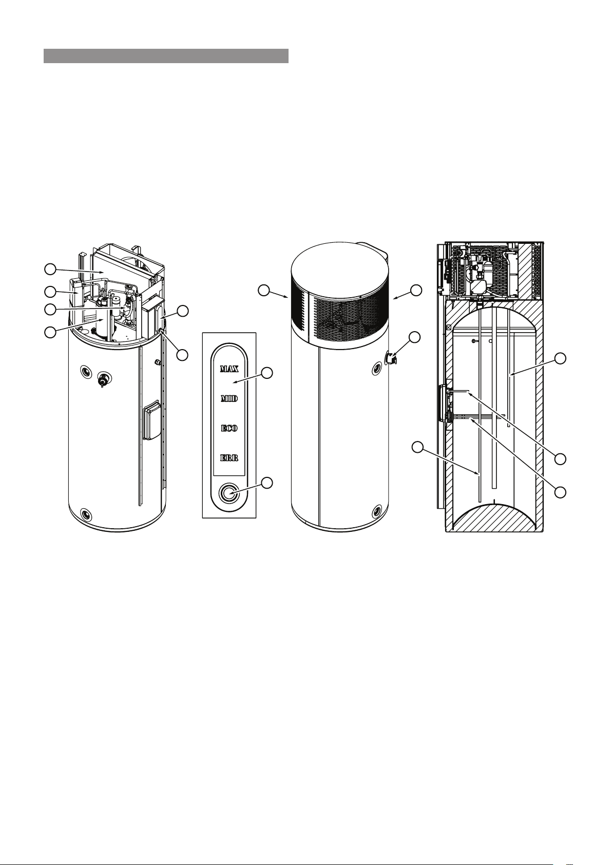
1. Cold water inlet pipe
2. Circulation Pump
3. Plate Heat Exchanger
4. Hot Water from Heat Exchanger to the Tank
5. Intake Air
6. Discharge Air
7. Fan Coil Unit
8. Compressor
9. Heating Element
10. Water Temperature Sensor
11. PTR Valve
12. Display & Control Panel
13. Mode Button
There are four indicators on the Display & Control Panel (12) which display the current operational mode /status of
the heat pump. To select one of the three available operation modes described below, press the Mode Button (13)
until the desired mode is illuminated.
MAX
For fast recovery the water will be heated to 60°C using a combination of the compression system and the
heating element.
MID
The water will be heated to 57°C using the compression system only.
ECO
The water will be heated to 55°C by economical use of the compression system (this is the factory default).
ERR
This will ash red only if an error is detected with the heat pump operation, please call Rinnai for assistance
if this should occur, and refer to “Save a Service Call” on page 10 for additional information.
6 5
11
1
9
4
10
7
3
2
8
12
12
13
13
WARNINGS AND IMPORTANT INFORMATION
Loading ...
Loading ...
Loading ...