Loading ...
I
Installation
Instructions
Split
System
Condensers
Installation/
Startup
Information
These
instructions
must
be
read
and
understood
completely
before
attempting
installation.
Installation
or
repairs
made
by
unqualified
persons
can
result
in
hazards
to
you and
others.
Installation
MUST
conform
with
local
building
codes
or,
in
the
absence
of
local
codes,
with
the
the
National
Electrical
Code
NFPA
70/ANSI
C1-1999
or
current
edition
and
Canadian
Electrical
Code
Part
1
CSA
C.22.1.
The
information
contained
in
this
manual
is
intended
for
use
by
a
qualified
service
technician
familiar
with
safety
procedures
and
equipped
with
the
proper
tools
and
test
instruments.
Failure
to
carefully
read
and
follow
all
instruc-
tions
in
this
manual
can
result
in
equipment
malfunction,
property
damage,
personal
injury
and/or
death.
After
uncrating
unit,
inspect
thoroughly
for
hidden
damage.
If
damage
is
found,
notify
the
transportation
company
im-
mediately
and
file
a
concealed
damage
claim.
CAUTION
Improper
installation,
adjustment,
alteration,
service
or
maintenance
can
void
the
warranty.
The
weight
of
the
condensing
unit
requires
caution and
proper
handling
procedures
when
lifting
or
moving
to
avoid
personal
injury.
Use
care
to
avoid
contact
with
sharp
or
pointed
edges.
Safety
Precautions
1.
Always
wear
safety
eye
wear
and
work
gloves
when
installing
equipment.
2.
Never
assume
electrical
power
is
disconnected.
Check
with
meter
and
disconnect.
3.
Keep
hands
out
of
fan
areas
when
power
is
connected
to
equipment.
4.
R-22
causes
frost-bite
burns.
5.
R-22
is
toxic
when
burned.
NOTE
TO
INSTALLING
DEALER:
The
Owners
Instruc-
tions
and
Warranty
are
to
be
given
to
the
owner
or
promi-
nently
displayed
near
the
indoor
Furnace/Air
Handler
Unit.
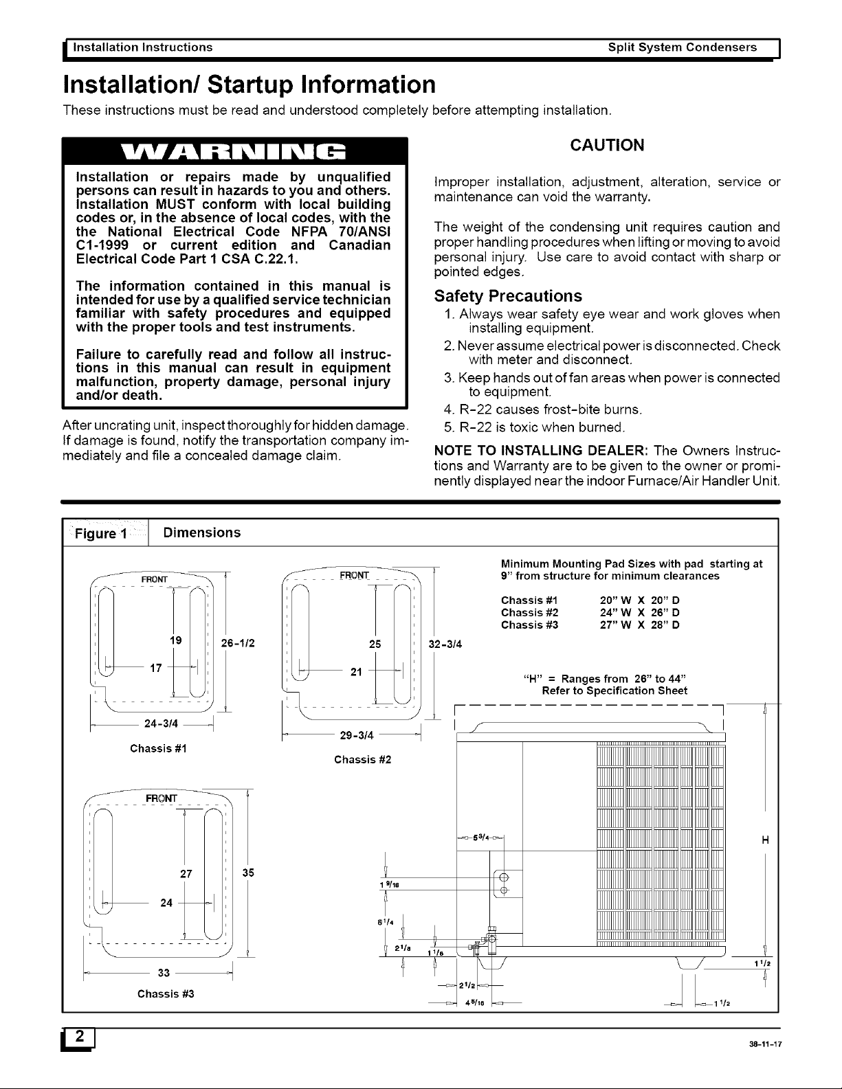
Dimensions
Figure
1
Chassis
#2
alla
Chassis
#3
—
29-314
——+
ie
JL!
Minimum
Mounting
Pad
Sizes
with
pad
starting
at
9”
from
structure
for
minimum
clearances
Chassis
#1
20”
W
X
20”D
Chassis
#2
24"
W
X
26”D
Chassis
#3
27”
W
X
28"D
“H”
=
Ranges
from
26”
to
44”
Refer
to
Specification
Sheet
itle
aife
38-11-17
Loading ...
Loading ...
Loading ...