Loading ...
Loading ...
Loading ...
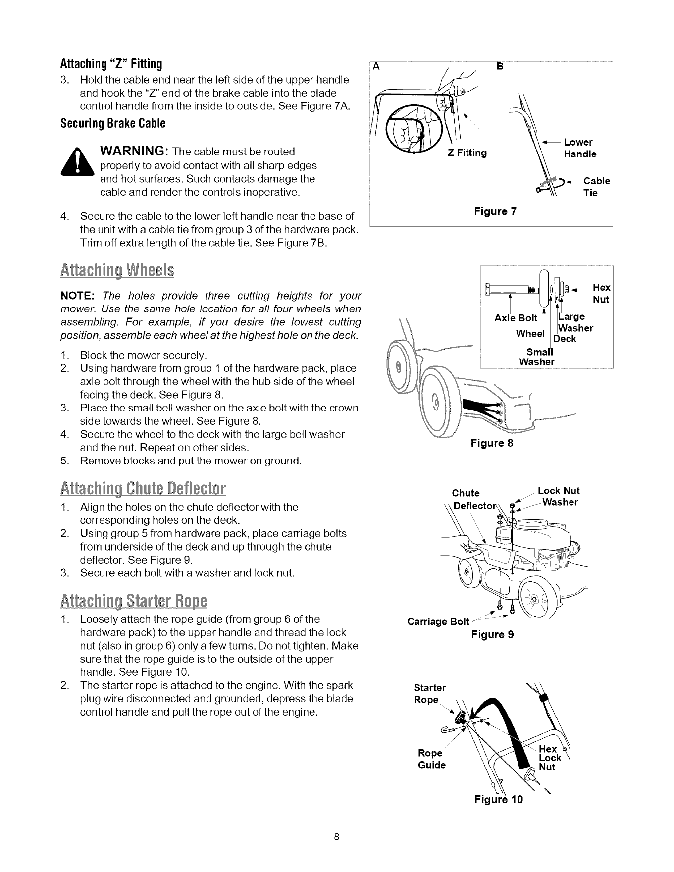
Attaching"Z" Fitting
3. Hold the cable end near the left side of the upper handle
and hook the "Z" end of the brake cable into the blade
control handle from the inside to outside. See Figure 7A.
SecuringBrakeCable
,_ WARNING: The cable must be routed
properly to avoid contact with all sharp edges
and hot surfaces. Such contacts damage the
cable and render the controls inoperative.
4. Secure the cable to the lower left handle near the base of
the unit with a cable tie from group 3 of the hardware pack.
Trim off extra length of the cable tie. See Figure 7B.
Atta@i Wheels
NOTE: The holes provide three cutting heights for your
mower. Use the same hole location for aft four wheels when
assembfing. For example, if you desire the lowest cutting
position, assemble each wheel at the highest hole on the deck.
1. Block the mower securely.
2. Using hardware from group 1 of the hardware pack, place
axle bolt through the wheel with the hub side of the wheel
facing the deck. See Figure 8.
3. Place the small bell washer on the axle bolt with the crown
side towards the wheel. See Figure 8.
4. Secure the wheel to the deck with the large bell washer
and the nut. Repeat on other sides.
5. Remove blocks and put the mower on ground.
Atta@i Oh@®Ddlecter
1. Align the holes on the chute deflector with the
corresponding holes on the deck.
2. Using group 5 from hardware pack, place carriage bolts
from underside of the deck and up through the chute
deflector. See Figure 9.
3. Secure each bolt with a washer and lock nut.
Atta@i 8 Starter
1. Loosely attach the rope guide (from group 6 of the
hardware pack) to the upper handle and thread the lock
nut (also in group 6) only a few turns. Do not tighten. Make
sure that the rope guide is to the outside of the upper
handle. See Figure 10.
2. The starter rope is attached to the engine. With the spark
plug wire disconnected and grounded, depress the blade
control handle and pull the rope out of the engine.
A B
Lower
Handle
_Catle
Figure 7
Figure 8
Chute
Lock Nut
=_j Washer
Carriage Bolt_ .....
Figure 9
Starter
Rope
Rope
Guide
Fig
Nut
\
10
Loading ...
Loading ...
Loading ...