MOTORIZED WATER SHUTOFF VALVE
1
7382283 (Rev. A 10/23/19)
The Motorized Water Shutoff Valve may be used with a
W
i-Fi connected water softener and the iQua™ app to
remotely turn off the home’s water supply. For
example, you may want to turn off the water when
going away on vacation. Install the motorized shutoff
valve in the plumbing, upstream of the softener (see
page 2), and plug the cable into the softener’s electron-
i
c control board with the power off (see page 2 and
Schematic Figure 1).
On the iQua™ app, near the bottom of the softener’s
main dashboard, there is a line labeled “Water Control”
with a button that, when pressed, alternates between
“Water On” and “Water Off”. If you receive an alert indi-
cating continuous water flow, you can use this control to
r
emotely shut off the water.
The system default for triggering a continuous water
flow alert is 20 minutes of flow at 0.4 gallons per minute
or higher. The time and water flow trigger values may
a
lso be adjusted in the “Alerts” section.
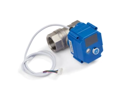
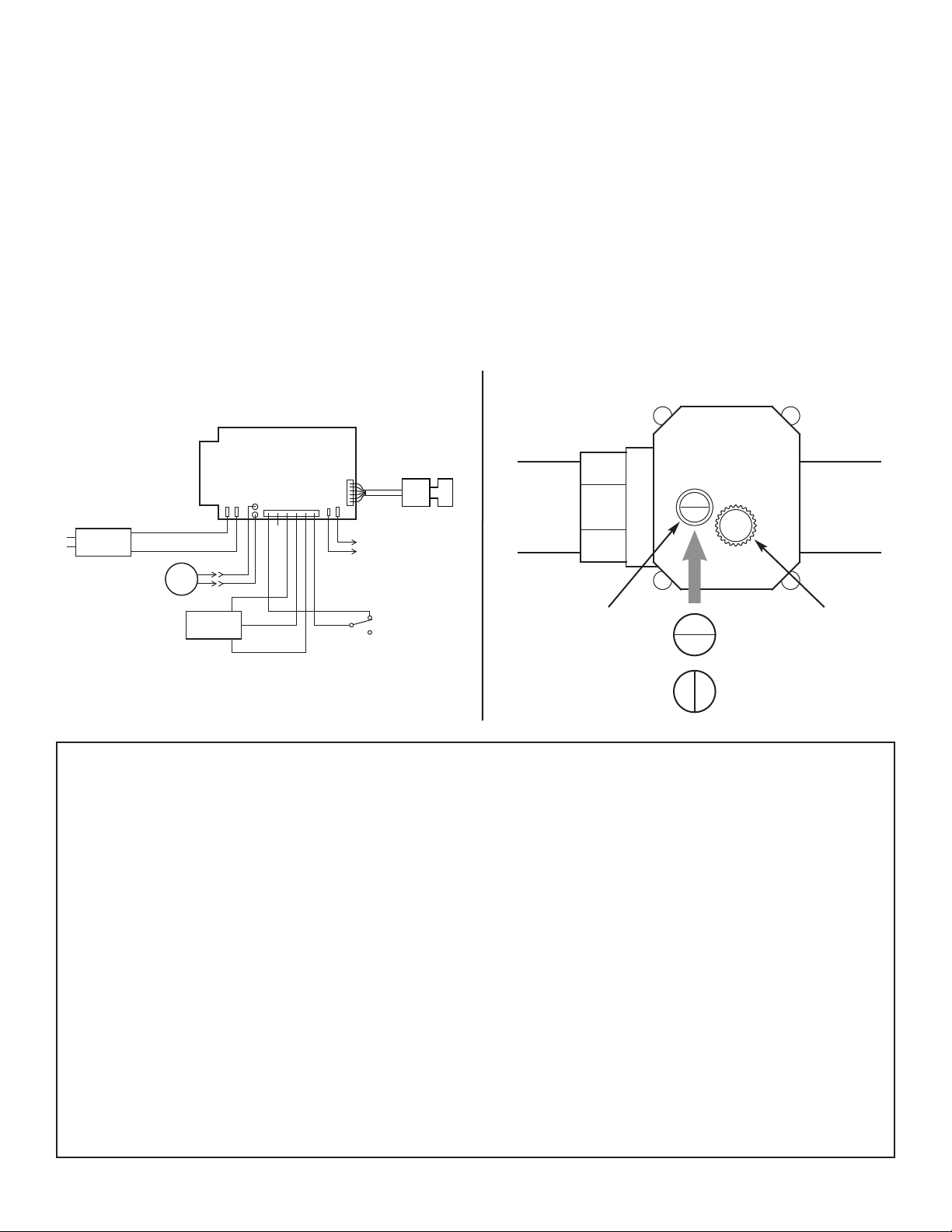
To manually operate the motorized water shutoff valve,
pull out the round knob on the valve and turn it until the
red line in the sight glass matches the desired (open or
closed) position. See Figure 2. If you manually
operate the valve, the app’s “Water Control” feature will
be disabled until you reset it by clicking “Yes” next to
the “Regain Control?” prompt.
OPEN
Motorized Water Shutoff Valve
Knob -
pull out
to turn
OPEN
CLOSED
Sight
glass
FIG. 2
ONE YEAR LIMITED WARRANTY
Warrantor: Ecodyne Water Systems, 1890 Woodlane Drive, Woodbury, MN 55125
Warrantor guarantees, to the original owner, that the Motorized Water Shutoff Valve, when installed and maintained in
accordance with the instructions, will be free from defects in materials and workmanship for a period of one year from date of
installation. If, within the first year, a part proves, after inspection, to be defective, Warrantor will, at its sole option, either replace
or repair the part without charge except installation charges. Labor to maintain the equipment is not part of the warranty.
TO OBTAIN WARRANTY PARTS, SIMPLY CALL 1-800-693-1604 for assistance. This warranty applies only while this product is
in use in the United States or Canada.
General Provisions
The above warranties are effective provided the Motorized Water Shutoff Valve is operated at water pressures not exceeding 100 psi, and at
water temperatures not exceeding 100°F; provided further that the Motorized Water Shutoff Valve is not subject to abuse, misuse, alteration,
neglect, freezing, accident or negligence; and provided further that the Motorized Water Shutoff Valve is not damaged as the result of any
unusual force of nature such as, but not limited to, flood, hurricane, tornado or earthquake. Warrantor is excused if failure to perform its warranty
obligations is the result of strikes, government regulation, materials shortages, or other circumstances beyond its control.
THERE ARE NO WARRANTIES ON THE WHOLE HOME WATER FILTRATION SYSTEM BEYOND THOSE SPECIFICALLY DESCRIBED
ABOVE. ALL IMPLIED WARRANTIES, INCLUDING ANY IMPLIED WARRANTY OF MERCHANTABILITY OR OF FITNESS FOR A
PARTICULAR PURPOSE, ARE DISCLAIMED TO THE EXTENT THEY MIGHT EXTEND BEYOND THE ABOVE PERIODS. THE SOLE OBLI-
GATION OF WARRANTOR UNDER THESE WARRANTIES IS TO REPLACE OR REPAIR THE COMPONENT OR PART WHICH PROVES TO
BE DEFECTIVE WITHIN THE SPECIFIED TIME PERIOD, AND WARRANTOR IS NOT LIABLE FOR CONSEQUENTIAL OR INCIDENTAL
DAMAGES. NO WARRANTOR DEALER, AGENT, REPRESENTATIVE, OR OTHER PERSON IS AUTHORIZED TO EXTEND OR EXPAND
THE WARRANTIES EXPRESSLY DESCRIBED ABOVE.
Some states do not allow limitations on how long an implied warranty lasts or exclusions or limitations of incidental or consequential damage, so
the limitations and exclusions in this warranty may not apply to you. This warranty gives you specific legal rights, and you may have other rights
which vary from state to state. This warranty applies to consumer-owned installations only.
Back of Electronic
Control Board
Valve
Motor
Power
Supply
Turbine
Sensor
Valve Position
Switch
Auxiliary
Output
Motorized
Water Shutoff
Valve
Wiring Schematic
FIG. 1
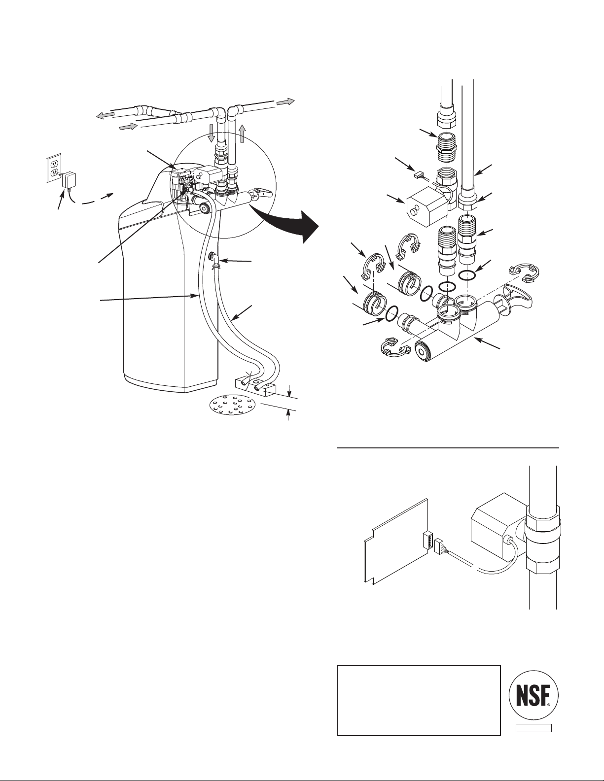
TYPICAL INSTALLATION
FIG. 3
Inlet
Outlet
Clips
P
ipe
To Outside
Faucets
1” NPT Sweat
Adaptor (not
included)
O-ring
Single
Bypass Valve
Lubricated
O-ring
Soft
Water
Hard Water
M
a
i
n
W
ate
r
Pi
pe
Water Softener
Valve
Valve Drain
Elbow
Valve Drain
Hose*
*Do not connect the
water softener valve drain
tubing to the salt storage
tank overflow hose.
Floor Drain
Overflow
Drain Elbow
Salt Storage
Tank Overflow
Hose*
Secure Valve Drain
Hose in place over
Floor Drain
1” NPT
Threaded
Adaptor
1-1/2”
air gap
Plug-in
Power
Supply
To
Controller
Motorized Water
Shutoff Valve
1” NPT Nipple
(provided with
m
otorized water
shutoff valve)
Plug into Controller
Optional Motorized
Water Shutoff Valve
Electronic Control
Board on back of
Faceplate
Plug cable into elec-
tronic control board
(power must be off)
FIG. 4
Install the Motorized Water Shutoff Valve
Install the water shutoff valve it in the plumbing upstream
of the softener inlet. Figure 3 shows installation with the
shutoff valve immediately upstream of the bypass valve
inlet, using one of the softener’s installation adaptors and
the 1” NPT nipple provided with the shutoff valve.
The shutoff valve may also be installed in the plumbing
farther upstream of the softener, making sure that the 10
foot long cable will reach the softener’s electronic control
board (See Figure 4). The shutoff valve’s inlet and outlet
are female 1” NPT. Support the weight of the shutoff valve.
After completing plumbing, make sure that the water
softener is not powered up, and plug the cable from the
shutoff valve into the corresponding connector on the elec-
tronic control board (See Fig. 4 or Schematic on Page 1).
CAUTION: Do not place fingers into the motorized shutoff
valve when it is plugged into the electronic controller.
NOTE: The shutoff valve may be operated manually by
pulling out and turning the knob on the shutoff valve body
(See Fig. 2 on Page 1), although there is no need to do this
when installing.
MOTORIZED WATER SHUTOFF VALVE (continued)
2
This valve has been tested and
certified by NSF International
against NSF/ANSI Standard 44
for structural integrity and
materials safety only.
COMPONENT