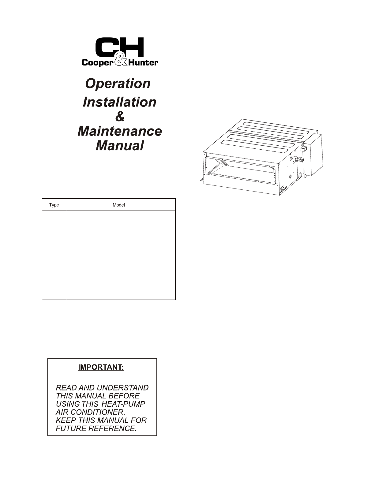
CEILING
TYPE
ORIGINAL INSTRUCTIONS
DUCTED
CHV-07SDHSP
CHV-09SDHSP
CHV-12SDHSP
CHV-15SDHSP
CHV-19SDHSP
CHV-24SDHSP
CHV-30SDHSP
CHV-38SDHSP
CHV-48SDHSP
CHV-54SDHSP
VRF INDOOR UNIT

Our company
Our company
our company.
International Organization for Standardization: (ISO 5149 or European Standard, EN 378).
Refer to Installation & Maintenance Manual of outdoor unit for temperature operation range.
Our company's
our company's
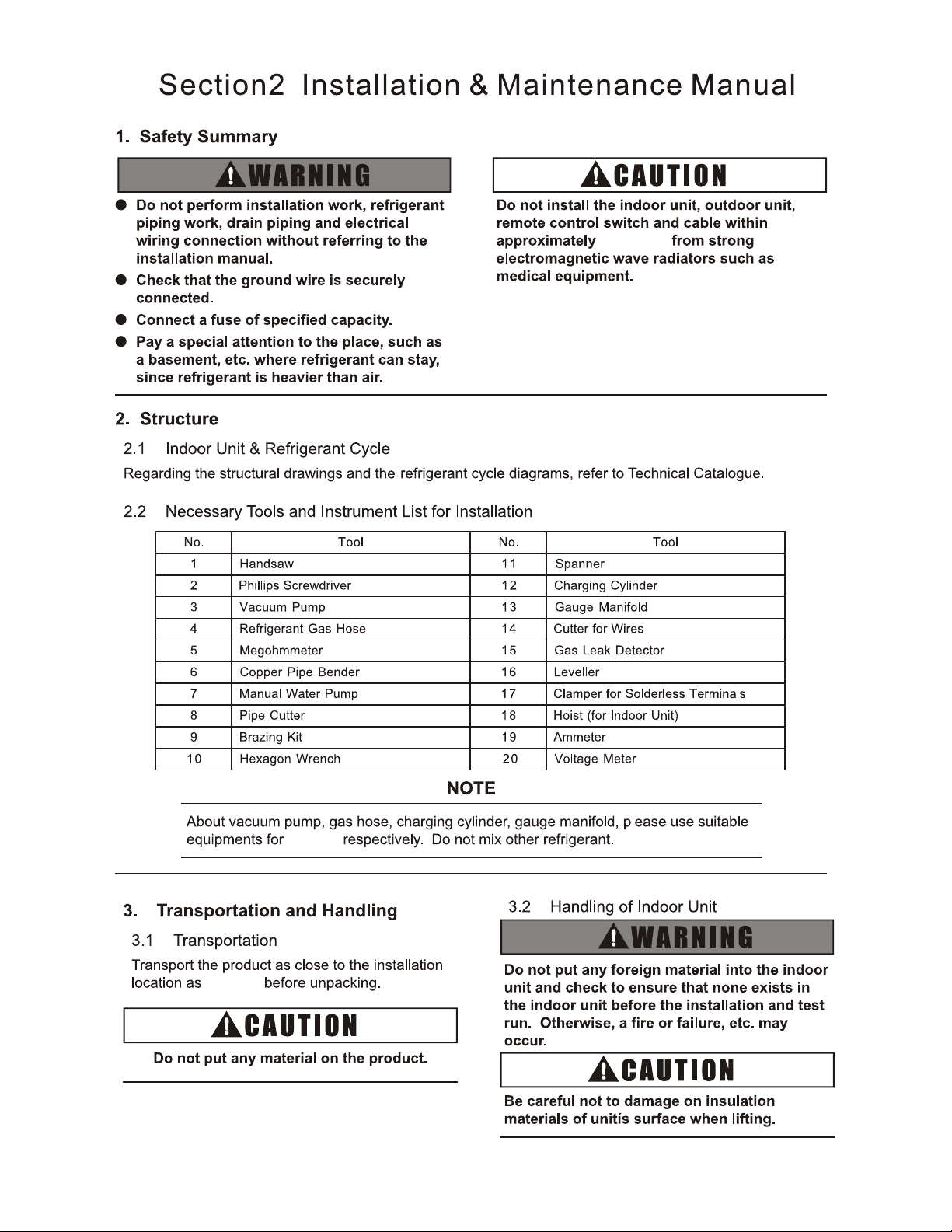
Section2 Installation & Maintenance Manual
3
3
3
4
4
4
4
4
6
6
6
6
6
6
6
7
7
8
8
5
5
5
5
5
8.1
8.2
8.3
Installation of the Filter
8.4
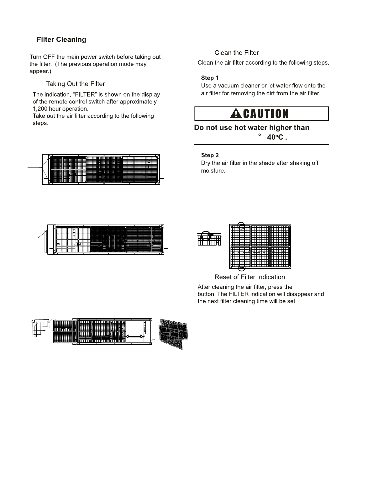
8. Filter Cleaning
13
13
13
14
15
15
15
16
11
11
11
12
15
12
09
07
19
24
30
38
Btu/h
3
10
48
l
l
l
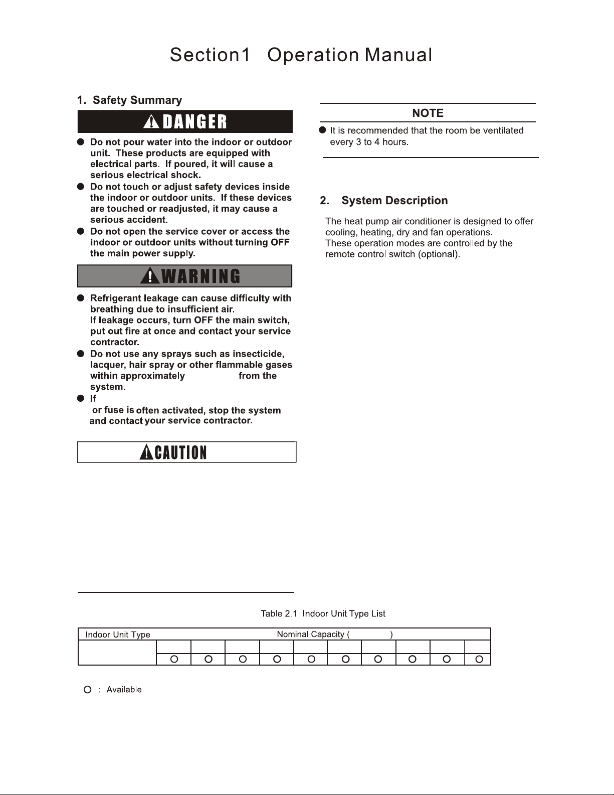
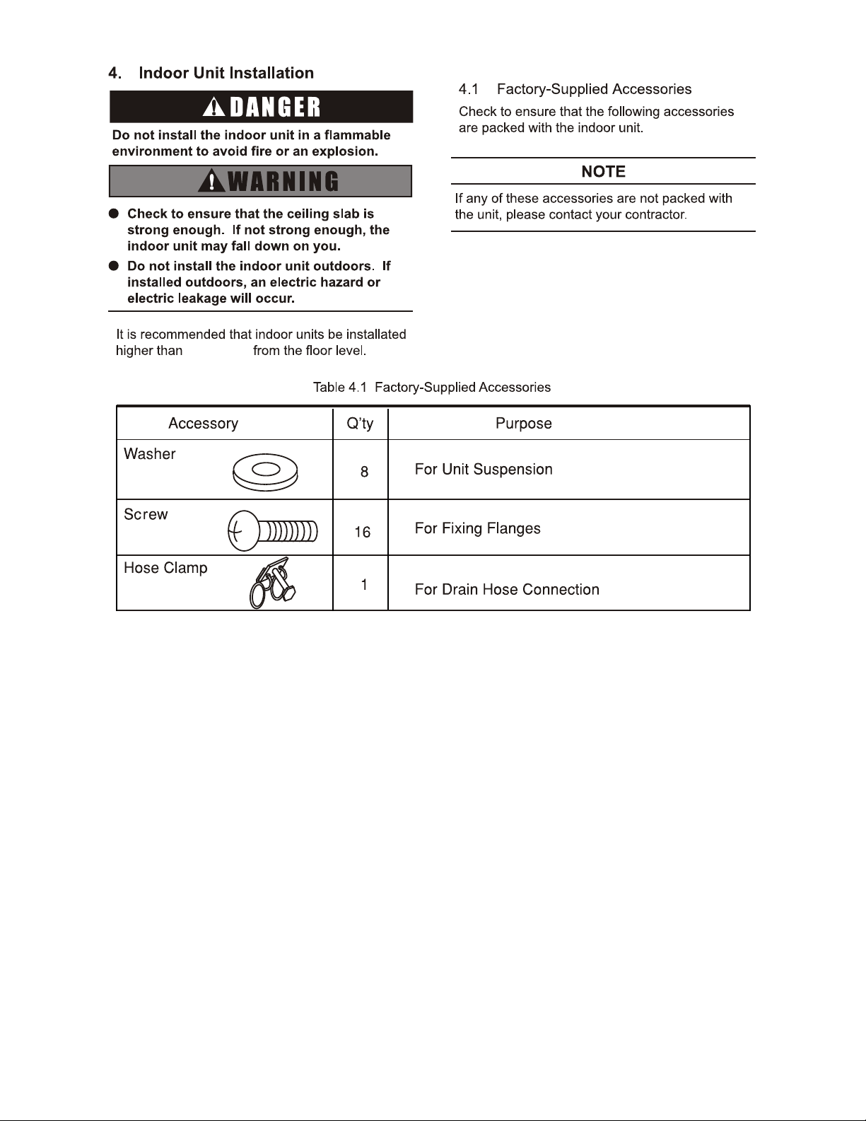
Children should be supervised so that they do
not play with the appliance.
The appliance should not be installed in the
laundry.
The appliance is not to be used by children or
unless they have been given supervision or
instruction concerning use of the appliance by a
person responsible for their safety.
CEILING
TYPE
DUCTED
1
3.3ft.(1m)
Ground Fault Circult Interrupter(GFCI)
54
2
1 r
61
o
F(16
o
C)
90 F(32
o
C)
Regarding the instructions of Wired Remote
Control Switch or Wireless Remote Control
Switch read the operation manual attached
to the control switch.
6. Automatic Control
3
122
F
122
F
( )
( )
)
7. Troubleshooting
4
80
F
(27 C)/80% R.H),
Self-clean:
During self-cleaning, the sound of sputter
may be heard, which is a normal physical
phenomena, and will disappear after cleaning.
8.
8.1
8.2
8.4
approximately
“FILTER”
Screws
Step 1
Remove two screws from the small plate next
to the electric box.
Step 2
Take out the small plate from the indoor unit.
Step 3
Take out the air filter from the air inlet grille Slots are
reserved for the tools in the front of the air filter Air filter
can be folded for multistage filters.
8.3
Installation of the Filter
The installation method is contrary to
the disassembly method But Install air
filter according to arrow direction.
5
104 F
( )
Small
Plate
R410A
6
9.8ft.(3m)
possible
8.2ft.(2.5m)
7
8
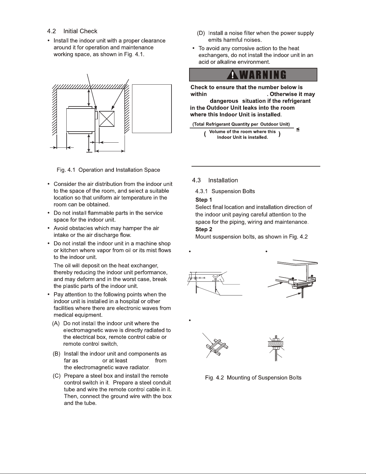
For Concrete Slab
Unit: in.
For Steel Beam
Beam
Suspension Bolt
(W3/8 or M10)
For Wooden Beam Suspension
Wooden Bar
(2-23/64 to 3-35/64 Square)
Wooden Beam
Nut
Nut
Square Washer
Square Washer
Suspension Bolt
Rear Side
≥ 39-3/8≥ 39-3/8
View from Top
Front Side
(5-1/8)
≥ 23-5/8
≥ 23-5/8
Electrical Box
Unit: in.
Service Access
Door (≥ 17-23/32)
In case that the
ceiling board can
not be detected
for servicing,
prepare a service
access door
below the indoor
unit for removing
the indoor unit.
9.8ft.(3m)
0.026lb/ft
3
0.026lb/ft
3
(
)
5-29/32 to 6-5/16
Insert
Anchor Bolt
(W3/8 or M10)
Steel
(221 to 331 lbs)
Concrete
(0.42kg/m³
0.42kg/m
3
This value should be decided according to the
each country's regulation such as ISO5149,
EN378 and ASHRAE Standard 15.
possible
la
07
15
19
24
30
38
48 54
9
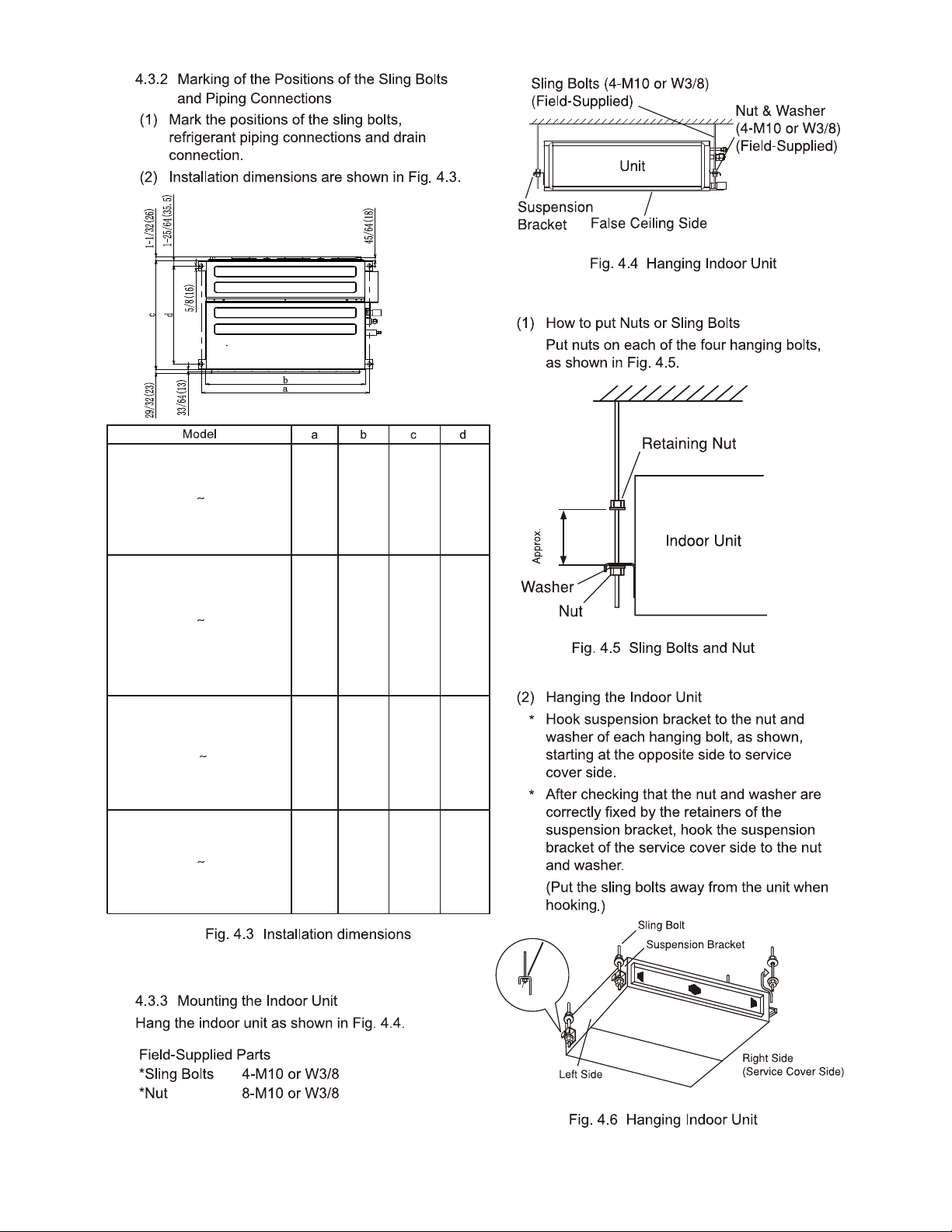
Nut &
Washer
Suspension
Bracket
Unit: in. (mm)
27-9/16 25-19/32 28-11/32 25-19/32
(
700) (650) (720) (650)
1-31/32 inch(50mm)
37-1/4 35-7/16 28-11/32 25-19/32
(
946) (650) (720) (650)
45-9/32 43-5/16 31-1/2 28-5/8
(
1150) (110)
(800) (727)
57-3/32 55-1/8 31-1/2 28-5/8
(
1450) (1400) (800) (727)
or Spmnt
10
13/64(5)
Unit: in. (mm)
17-23/32 in. ×17-23/32 in.
Voltage Model
Static Pressure
in.W.G.(Pa)
024
0.2
(0)
/0.0
(30
(0)
/10)
0.20
(0)
/0.0
(0
(0)
/200)
230V
2208/
304
(0~5mm)
(0):
013/64in.
An excess or a shortage of refrigerant is the
main cause of trouble to the units.
Charge refrigerant by the correct quantity.
Flaring Dimension
Perform the flaring work as shown below.
R410A
(*) It is impossible to perform the flaring work with
1/2H material. In this case, use an accessory
pipe(with a flare).
1/4(6.35)
3/8(9.53)
1/2(12.7)
5/8(15.88)
3/4(19.05)
1/32(9.1)
33/64(13.2)
21/32(16.6)
25/32(19.7)
(*)
Diameter
A
+0
-1/64(0.4)
07
15
19
24
30
38 54
10A
11
Unit: in. (mm)
Optional pump
1/64 ~ 1/32R
φA
φd
90
o
+
2
o
45
o
+
2
o
Required Tightening Torque
Pipe Size
φ
1/4 in. (6.35 mm)
φ
3/8 in. (9.53 mm)
φ
1/2 in. (12.7 mm)
φ
5/8 in. (15.88 mm)
Tightening Torque
10.3 - 13.3 ft·lbs (14 - 18 N·m)
25.1 - 31.0 ft·lbs (34 - 42 N·m)
36.1 - 45.0 ft·lbs (49 - 61 N·m)
50.2 - 60.5 ft·lbs (68 - 82 N·m)
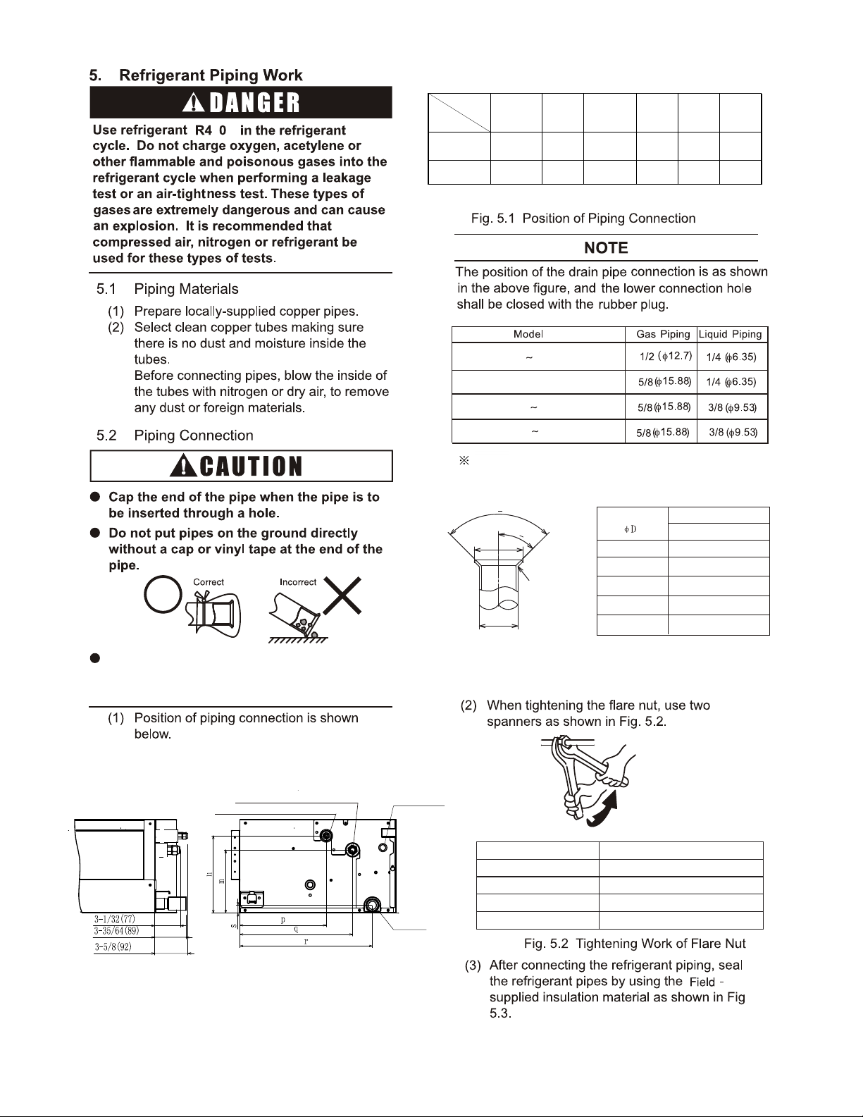
Drain Pipe Connnection
Refrigerant Liquid Pipe Connection
Refrigerant Gas Pipe Connection
Drain Pipe Connection
mn p qrs
0724
7-11/64
(182)
8-47/64
(222)
9-11/16
(246)
12-41/64
(321)
14-27/32
(377)
29/32
(23)
3054
5-29/32
(150)
7-31/64
(190)
10-5/8
(270)
13-37/64
(345)
15-25/32
(401)
55/64
(22)
Model
Dimension
Unit: in.(mm)
Unit: in.(mm)
Optional pump
Drain Pipe
12
9-1/4(235)
14-31/32(380) 31/32(25)
2-9/32(58)
2-9/32(58)
31/32
(25)
31/32
(25)
7-13/32
(188)
1
1-15/32(291)
1-31/32(50) to
22-11/16(576) (Max.)
14-23/32(374) to 35-7/16(900) (Max.)
(Drain-Up Length)
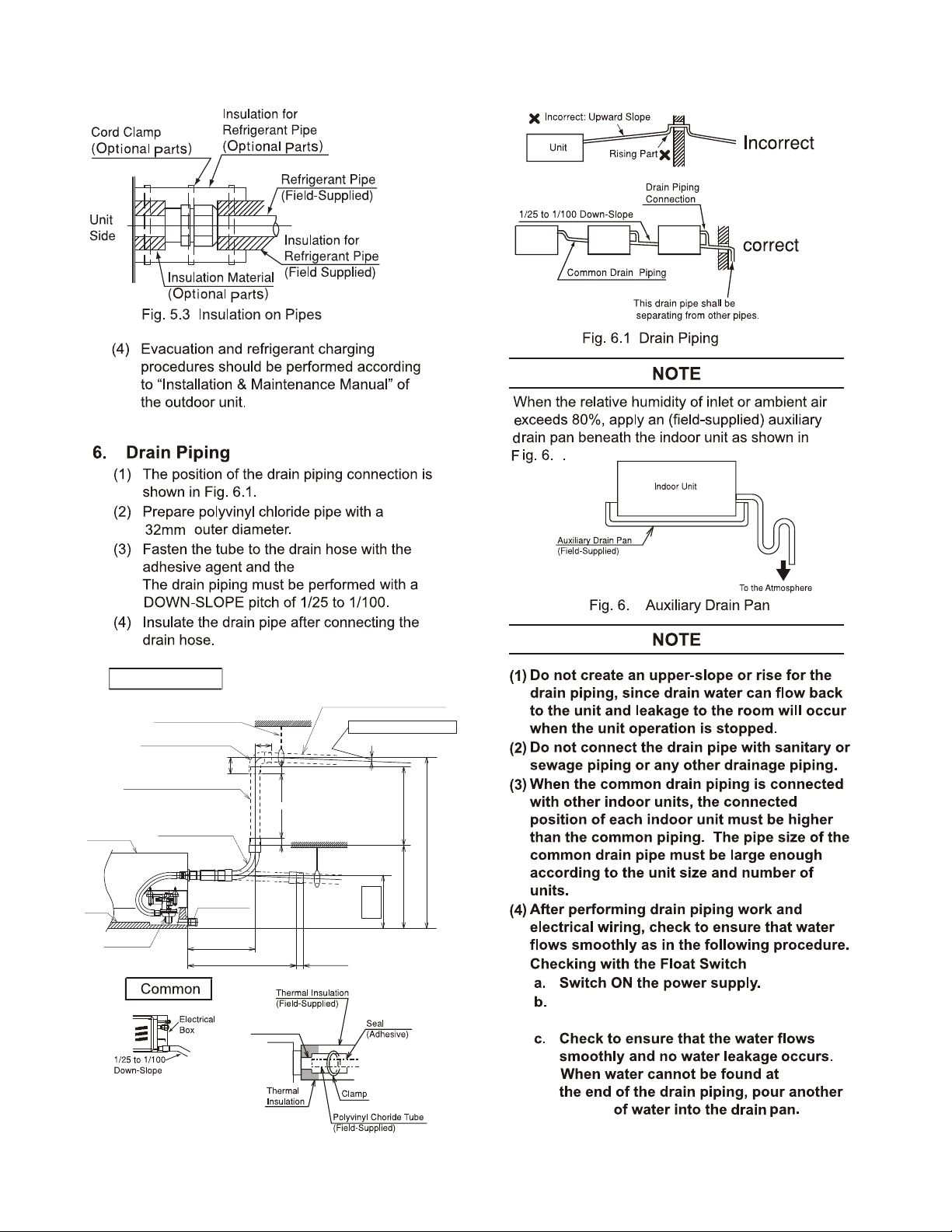
Drain Piping (PVC Tube, VP25)
(Field-Supplied)
1/25 to 1/100 Down-Slope
Suspension Bracket
(Field-Supplied)
90
o
Elbow Pipe (VP25)
(Field-Supplied)
Lift Piping for Drain-Up
(PVC Tube, VP25)
(Field-Supplied)
Indoor Unit
Drain Pump
Drain
Pan
Rubber Boss
Drain Hose
(L: 11-13/16 (300))
(Accessory)
Unit: in. (mm)
Pour 2 to 2.5 liters of water into the
drain pan.
2 liters
1-1/4in.
( )
2
2
-upp camp
All electrical work must be done as outlined in this
manual and in accordance with this manual.
Substandard work can result in fire and damage to the
unit.
Use specified cables between units and choose the
cables correctly. If not, an electrical shock or fire may
occur.
Do not open the service cover or access panel for the
indoor or outdoor units without turning OFF the main
power supply. It can result in an electrical shock.
Turn OFF the main power switch of the indoor unit and
the outdoor unit before attempting any electrical wiring
work or a periodical check is performed. If not, it will
result in an electric shock or a fire.
Check to ensure that the indoor fan and the outdoor fan
have stopped before attempting any electrical wiring
work or for any scheduled electrical work that is being
performed.
The wires must be firmly secured. External force applied
to terminals may cause a fire.
It is forbidden to connect a plurality of power lines into
one power terminal block. At the indoor unit side of air
conditioner, power wiring can be extended through a
power distribution box. Be sure to calculate the wiring
capacity carefully, since excessively low wiring capacity
may frequently cause fire.
Do not start the system before all check points are
thoroughly checked.
Wrap the accessory packing around the wires, and plug
the wiring connection hole with the seal material to
protect the product from any condensate or insects.
Tightly secure the wires with the cord clamp inside the
indoor unit.
Secure the cable of wired control using the cord clamp
inside the electric box.But North American products,
Local safety standards are adopted for power wiring.
Tighten screws to the following torques.
1
13
M3.5: 0.9 ft·lbs (1.2 N·m)
M4: 0.7 to 1.0 ft·lbs (1.0 to 1.3 N·m)
M5: 1.5 to 1.8 ft·lbs (2.0 to 2.4 N·m)
M6: 3.0 to 3.7 ft·lbs (4.0 to 5.0 N·m)
M8: 6.6 to 8.1 ft·lbs (9.0 to 11.0 N·m)
M10: 13.3 to 17.0 ft·lbs (18.0 to 23.0 N·m)
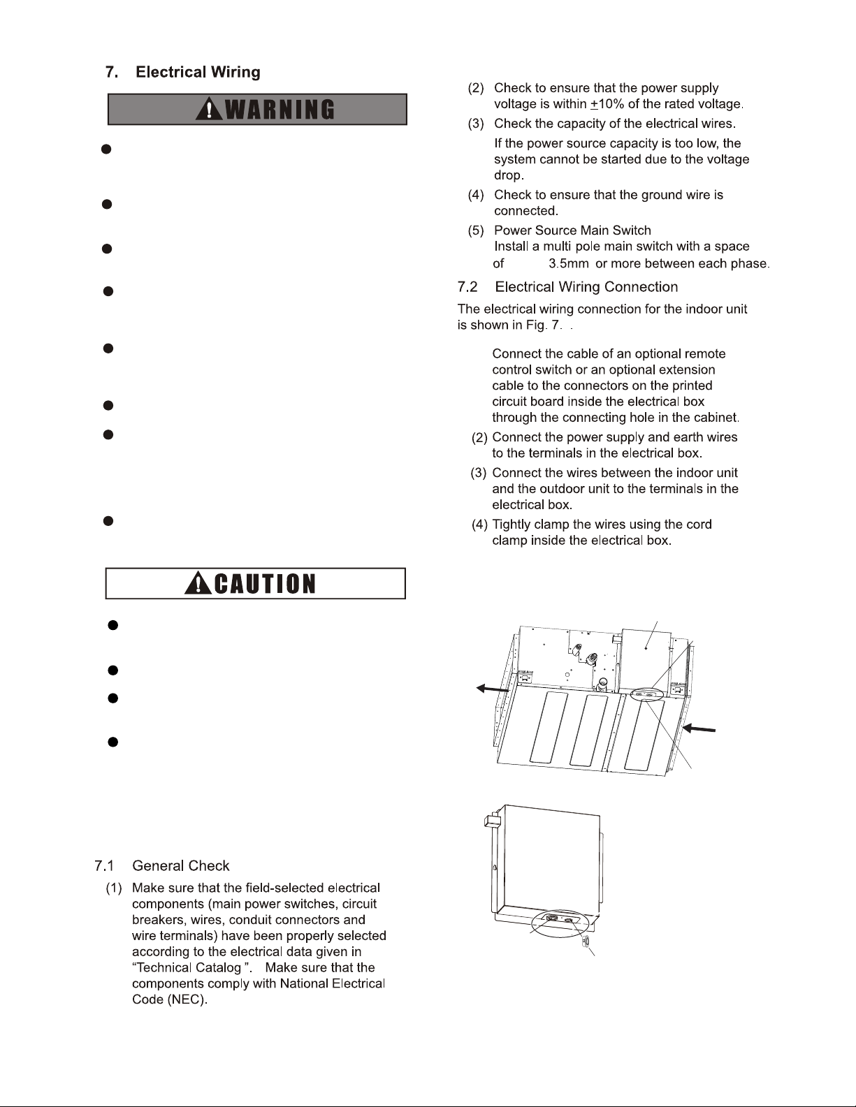
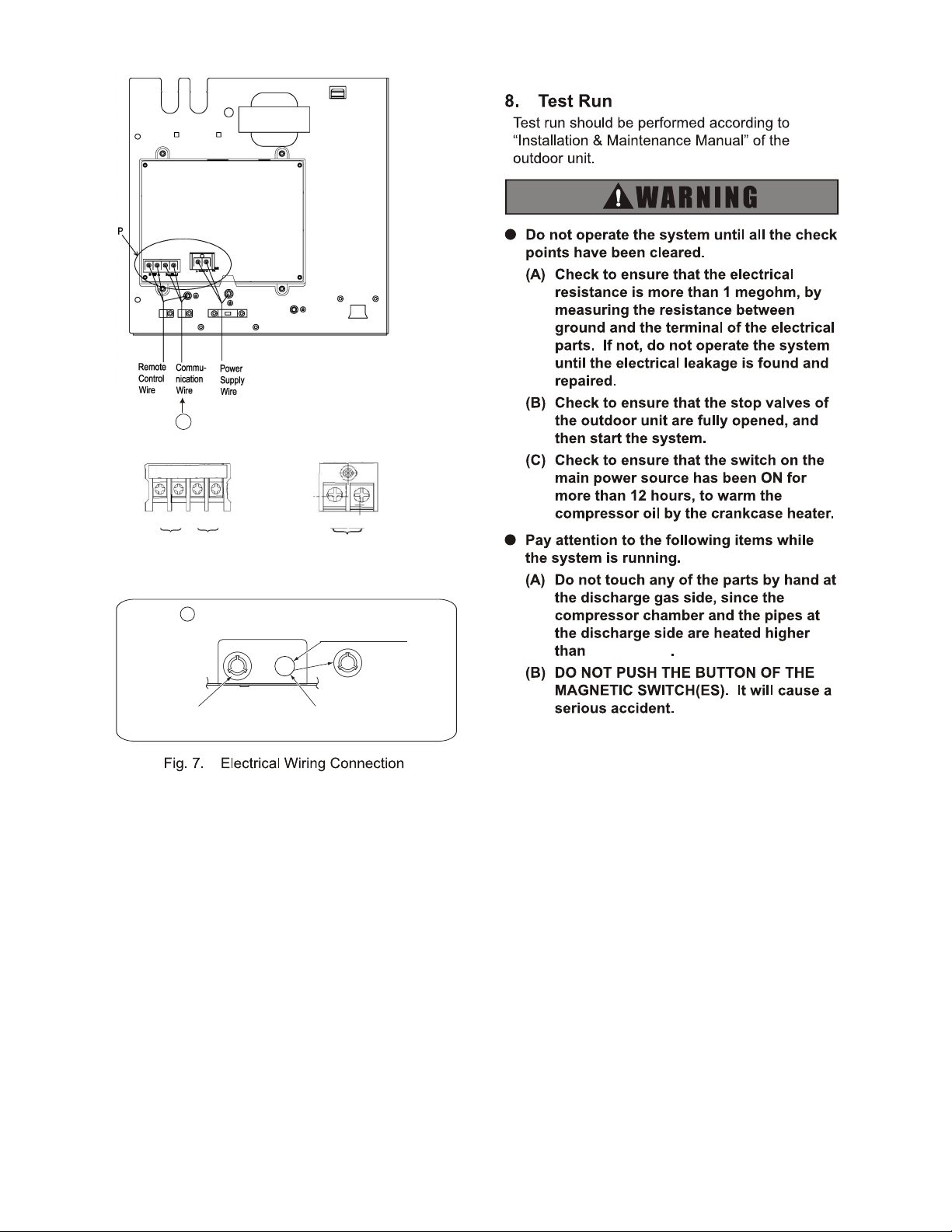
Enlarged View of A Part
Wiring Grommet
Wiring Grommet
(1)
9/64in.( )
Connecting Hole
Electrical Box Cover
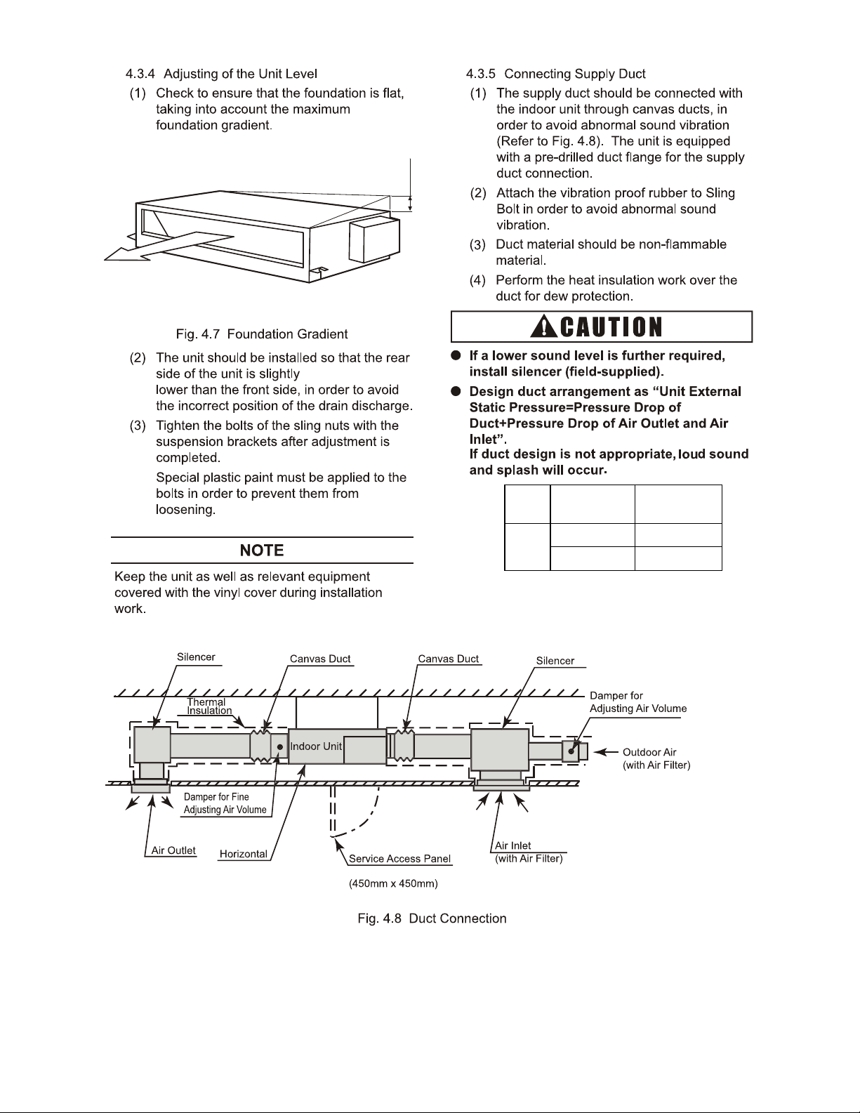
Air Outlet
Air Inlet
A
1
2
A
B
L2
L1
208230V~60Hz
Wired
Remote
Control
Wire
Communication
Cable
Power Cord
Enlarged View of P Part Terminal Block (TB) Wiring
1
14
B
View from B
55/4 in. (φ22.2mm)
Conduit Hole
Connecting Hole for
Communication Cable
Connecting Hole for
Power Supply Wiring
194
o
F(90
o
C)
07 54
15
This equipment can be installed with a Ground Fault Circuit
Interrupter (GFCI), which is a recognized measure for added
protection to a properly grounded unit. Install appropriate sized
breakers /fuses / overcurrent protection switches and wiring in
accordance to local, state and NEC codes and requirements.
The equipment installer is responsible for understanding and
abiding by applicable codes and requirements. Failure to use a
GFCI can result in electrical shock or fire.
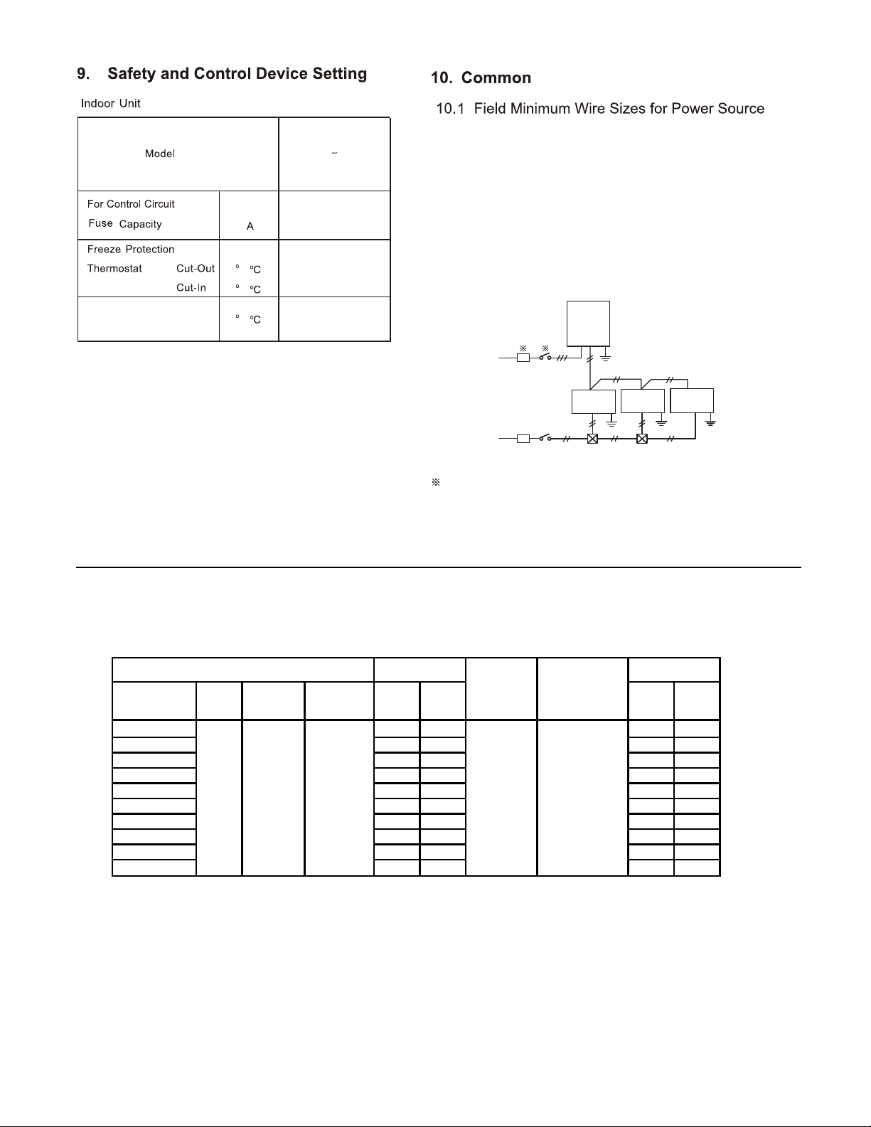
Select wiring capacity according to the table 10.1. Install a GFCI
(Ground Fault Circuit Interrupter) and main switch as shown in
each of the system diagrams below.
Outdoor
Unit
Indoor
Unit
Switchbox
Outdoor Unit
Power Supply
Indoor Unit
Power Supply
Indoor
Unit
Indoor
Unit
GFCI
Main
Switch
GFCI
Main
Switch
Refer to the “Installation and Maintenance Manual” for the connected
outdoor unit for details of wire, GFCI and main switch for outdoor unit.
Table 10.1 Recommended Wiring Capacity and Size
F( )
F( )
32(0)
58(14)
Model Hz Volts
Voltage
range
MCA MOP kW FLA
0 . 2.4
0.0 0.
.
2.4
0.0 0.
1.
2.4
0.0
0.
1.
2.4
0.0
2.2 3.
0.20
.00
2.2 3.
0.20 1.00
2.
0.20 1.00
2.
4.4
0.20
.00
.04
4.4
0.3
.40
0
2
24
30
3
4
4
.04
.0
0.3
.40
Units Power supply
Power
supply
wiring size
Communication
Cable Size
Fan motor
60
208230V 18-253V
Wiring size
and length
must
comply with
local codes.
AWG18
(0.82mm
2
)
(Field supply)
(Field supply)
Select a GFCI according to the Max. Overcurrent Protective Device (A).
MCA: Min. Circuit Amps (A)
MOP: Max. Overcurrent Protective Device (A)
FLA: Full Load Amps (A)
.0
0.
Set Temperature
Difference
4(2)
F( )
10
Line
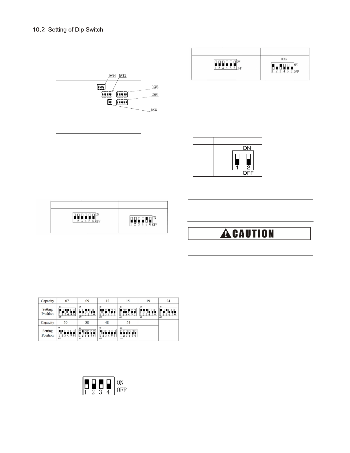
(1) DIP switch must be set with power sources of the indoor
and outdoor units in OFF state. Otherwise, the settings are
invalid.
(2) The location of DIP switch is shown in the figure below.
(b)
Capacity Code Setting (DSW3)
No setup is required.
The code is set before delivery. This switch is used to
set the capacity of indoor unit.
(a)
(3) The PCB of indoor unit is furnished with 5 DIP switches
that must be set based on the following requirements
before test run. The system must not be started before
the completion of DIP setup.
All indoor units must be numbered (DSW6) as shown
in the figure below. The outdoor unit numbering must
start with "0".
(c) Model Code Setting (DSW4)
No setup is required. The code is set before delivery.
Default No.1 and 3 ON.
Note:
Symbol "■" indicates the location of DIP switch.
The position indicated in the diagram is in the factory-set
state.
The power supply shall be turned off before the setup of
DIP switch. Otherwise, the settings will be invalid.
(d) Cooling System Code No. Setting (DSW5)
The setup is needed. All are set to OFF before delivery.
Refrigerant System Setting
Ex.) Set system No. 5
DSW5 are set to "0" before delivery. 64 indoor units can be
connected.
(e) Other function setting (DSW9)
No setup is required. The code is set before delivery.
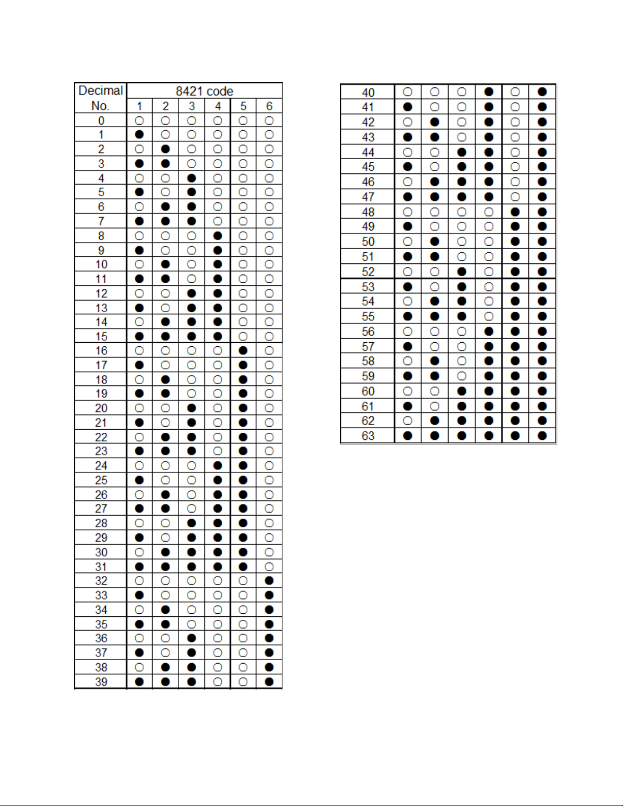
DSW6(Setting 0~63)
Ex.)Set machine No.16
No.5 ON
DSW6 are set to "0" before delivery. 64 indoor units
can be connected.
DSW5(Setting 0~63)
16
9
Model
models
Setting
Position
mar or DS - nary 8421 co
comparon a on n pa
mar or DS5 - nary 8421 co
comparon a on n pa
17
ppn Comparon a o 8421 Co an
Dcma o
:The current position is set to OFF
:The current position is set to ON

08.2022 V00
The Company is committed to continuous product improvement. We reserve the right, therefore, to alter the product information
at any
time and without prior announcem
ent.