Loading ...
Loading ...
3
Installation
Note: The illustrations may differ somewhat from your PDU
model.
1
Determine Installation Configuration. The PDU
supports four primary installation configurations: 1U
Rack, 0U Rack, Wall and Under-Counter. Choose a
configuration and follow the installation instructions
in the appropriate section of Step 1 before
proceeding to Step 2.
Note: Regardless of installation configuration, the
user must determine the fitness of hardware and
procedures before mounting. The PDU and included
hardware are designed for common rack and rack
enclosure types and may not be appropriate for all
applications. Exact mounting configurations may vary.
1-1
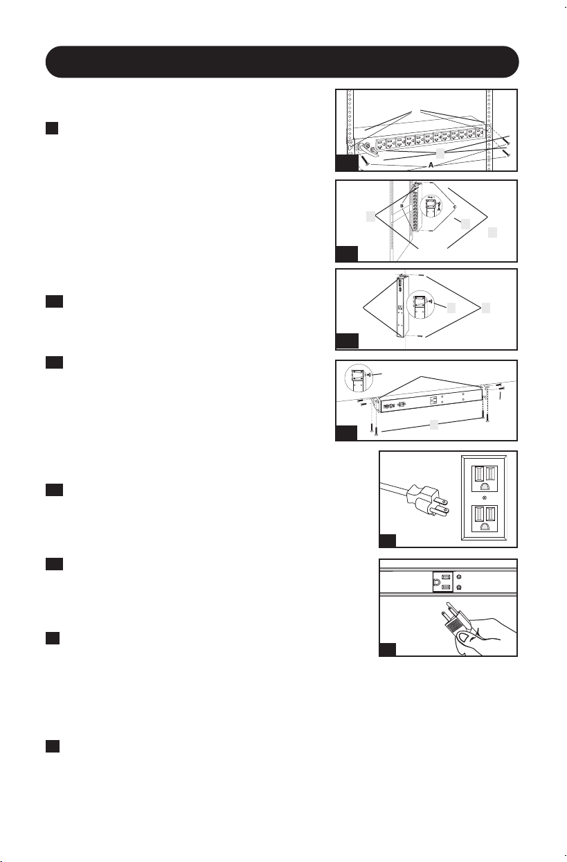
1U Rack Installation. Attach the PDU to the rack by
inserting four user-supplied screws (A) through the
PDU mounting brackets (B) and into the mounting
holes of the rack rail as shown.
1-2
0U Rack Installation. Part 1: Remove the screws
(C) attaching the mounting brackets to the PDU,
change the orientation of the brackets as shown and
reattach the brackets. Use only the screws supplied
by the manufacturer or their exact equivalent (#6-
32, 1/4” flat head). Part 2: Attach the PDU vertically
by inserting two or more user-supplied screws (A)
through the PDU mounting brackets (B) and into
mounting points in the rack or rack enclosure.
1-3
Wall Installation. After repeating Part 1 above,
attach the PDU to a stable mounting surface by
inserting two or more user-supplied screws (A)
through the PDU mounting brackets (B) and into
secure mounting points on the mounting surface.
1-4
Under-Counter Installation. After repeating Part 1
above, attach the PDU to a stable mounting surface
by inserting four user-supplied screws (A) through the
PDU mounting brackets (B) and into secure mounting
points on the mounting surface.
2
Attach the input plug of the PDU to a grounded
outlet. Insert the plug directly into a grounded outlet
that does not share a circuit with a heavy electrical
load (such as an air conditioner or refrigerator).
2
1-1
1-2
1-3
1-4
A
B
B
A
C
A
B
C
B
C
A
C
3
Note: Select models include an input plug adapter that converts the twist-lock input plug to a
straight-blade input plug. Attach the input plug adapter to the input plug if you wish to plug
the PDU into a compatible straight-blade outlet.
3
Attach equipment to the PDU. Do not exceed the load rating of the PDU. The total electrical
current used by the PDU will be displayed on the digital meter in amperes.
21-03-405 93-338A.indb 321-03-405 93-338A.indb 3 4/1/2021 1:25:37 PM4/1/2021 1:25:37 PM
Loading ...
Loading ...
Loading ...