– 2 –
– 5 –
– 9 –
– 3 – – 4 –
– 6 –
– 10 –
– 7 –
– 11 –
– 8 –
– 12 –
LR60 & LR60W
Laser Receiver
User Guide
•
Introduction
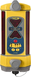
Thank you for choosing the Spectra Precision
®
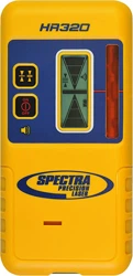
Laser Receiver LR60. The laser receiver
is a rugged, multi-purpose, electronic sensor that detects laser light generated by
rotating laser transmitters. The receiver works with nearly all models of rotating lasers
and detects both visible and invisible beams.
Before using the receiver, be sure to read this user guide carefully. Included in it is
information about setting up, using, and maintaining the receiver. Also included
in this manual are WARNINGS!, CAUTIONS, and Notes. Each of these words
represents a level of danger or concern. A WARNING! indicates a hazard or unsafe
practice that could result in serious injury or death. A CAUTION indicates a hazard or
unsafe practice that could result in minor injury or property damage. A Note indicates
important information unrelated to safety.
Your comments and suggestions are welcome; please contact us at:
Trimble - Spectra Precision Division
5475 Kellenburger Road
Dayton, Ohio 45424-1099 U.S.A.
Phone: (937) 245-5600 / (800) 538-7800
Fax: (937) 233-9004
NOTE: The LR60W ships configured to wireless (Radio) communication mode
for use with a RD20 remote display. Wireless operation is indicated by the
Communications Radio Link symbol on the LCD. To change to wired (RS-485)
mode for use with a control box, simultaneously press the power, deadband and
display brightness buttons (make sure the receiver is powered up first). Pressing this
3-button combination will toggle the receiver between wireless (Radio) and wired (RS-
485) modes as indicated by the following:
Radio Mode Indication: The two outer on-grade LEDs double-blink every few seconds
Wired (RS-485) Mode Indication: The center on-grade LED double-blinks every few
seconds
Once configured the receiver will remember it’s setting after a power cycle. For
additional wireless RD20 operating features please see the RD20 User Guide.
Safety
Please follow all operating and safety instructions in this guide and that of your
machinery. Perform periodic checks of the product’s performance. Trimble or its
representatives assume no responsibility for results of the use of this product including
any direct, indirect, consequential damage, and loss of profits. Check your work
frequently.
WARNING: When working near construction or agricultural machinery, follow
all safety precautions as described in the machinery’s user guide.
WARNING: When excavating, follow all excavation and trench safety regulations
and practices.
WARNING: Be aware of all overhead obstructions and electrical power lines.
The receiver and mast may be higher than the machinery. Remove when transporting
machinery.
CAUTION: Do not disassemble any part of the receiver other than to replace
batteries. The receiver is to be serviced by authorized Trimble service personnel only.
Maintenance and Care
Your receiver was shipped in a protective carrying case. If the receiver is transported
from job to job inside its protective case and normal instrument precautions are
followed, the receiver will provide many years of service. When storing the receiver,
be sure to store it in its carrying case.
Do not wipe dust or dirt off the receiver with a dry cloth as scratching could occur,
possibly damaging these surfaces. Use only a good quality glass cleaner with a soft
cloth on all external components. If these surfaces have hardened concrete or other
materials on them, take the system to your Authorized Service Center for cleaning.
If the receiver will not be used for more than 30 days, remove the alkaline batteries
from it. Be sure to dispose of all batteries properly. Refer to your state or local
requirements for the disposal information.
Controls and Displays
Battery Safety
Built-in overcharging protection prevents damage to the receiver if it is left on charge
after being fully charged. Charge protection also prevents damage if you accidentally
try to recharge alkaline batteries.
CAUTION: Do not attempt to charge alkaline or other disposable batteries.
Note: The batteries should only be charged when the receiver is between 0 °C to
45 °C (32 °F to 113 °F).
The rechargeable battery electronics include charge status and charge-error indicators
located on the back of the housing.
Using the Receiver
Operation
Power Button
Press the power button. All the LEDs light and then each row lights from top to
bottom. The LCD cycles through its symbols. If the receiver is out of the laser beam,
the center green LED flashes and the LCD lights to confirm power is on. If the
receiver is in a laser beam, a corresponding LED grade display lights.
Plumb Button
This plumb button has three positions: off, standard, and Angle Compensation
for Excavation (ACE) mode. Plumb indication is generally used during excavation
operations.
Press the button once to change between standard plumb mode and
plumb off. The standard plumb mode is preset to a range of ±2.5°.
The LCD does not show a plumb symbol when it is turned off; it
shows the standard plumb indicator when the standard plumb mode
is selected. The grade indication LEDs flash quickly when the mast
and receiver are extended beyond the plumb range and flash slowly when retracted
beyond the range. The display is solid when the mast and receiver are within the
plumb range.
Angle Compensation for Excavation (ACE) Mode
The receiver displays grade information at wide swing angles of
±10° to 30°. To enter this mode, press and hold the plumb button
for approximately 2 seconds. The on-grade location automatically
switches to the center on-grade and the wider plumb angle symbol
appears on the LCD. A single LED or pair of LEDs light. These
LEDs correspond to the setup length that is input using the scale on the front label of
the display area. A setup procedure is required to compensate for the dipper-arm swing
arc. To determine this length and for more installation information, please refer to the
“Installation-General” section of this guide.
Center/Offset On-Grade Button
Center on-grade or “grading mode” is selected when grade information is useful both
above and below on-grade, as with typical grading operations. Offset on-grade or
“excavator mode” is selected when using a backhoe or excavator. The excavator mode
gives more information and a larger display above on-grade.
Press the button to cycle between the two options. The LCD indicates which mode
is selected and the LEDs display the appropriate pattern. The center on-grade has 7
display channels plus 2 out-of-beam indications. The offset on-grade has 8 display
channels plus 2 out-of-beam indications.
Display-Brightness Button
The display-brightness button controls the LED brightness. Options
include Bright and Dim. Use Dim for normal and lower light
conditions and Bright for sunny daytime operation. Dim conserves
battery life by approximately 50%. Press the display-brightness
button to cycle through both options. The selection is indicated on
the LCD. Additionally, if the receiver is out of the laser beam, the
LEDs display a circle with the current setting.
Out-of-Beam Indication
The LED display indicates if the receiver has moved beyond the vertical laser-reception
range. A sequence of LEDs indicates which direction the implement must be moved
to pick up the beam. The out-of-beam indication continues for approximately two
minutes.
Out-of-Beam Indication Disable
The out-of-beam indication can be turned off if desired. Press the two outer buttons
(Plumb and Display Brightness) at the same time to disable. The receiver displays
the out-of-beam LED sequence in reverse order from both top and bottom. When
disabled, the receiver indicates out-of-beam by flashing the center LED. Press the two
outer buttons again to enable the indication. The receiver remembers the out-of-beam
display state at the next power up.
Installation
General
1. Set up the laser in a safe and convenient location. For more information about laser
setup, please refer to the laser’s user guide.
Note: Operating distances depend on the rotating laser power. The receiver can
pick up the beam from all directions (360°), but it requires a clear line of sight to
the laser.
2. If your laser has selectable rotation speeds, select a high rotation speed. The receiver
can process speeds up to 1200 RPM.
3. To mount the receiver on the mast, turn both the top and bottom knobs
counterclockwise until the mounting clamps in back open enough to fit around
the mounting mast. Place the receiver on the mast. Turn the knobs clockwise to
tighten.
Note: The receiver will mount to round tubing that has a 42 mm to 50 mm
(1.66 in. to 2.00 in.) outside diameter or to 38 mm (1-1/2 in.) square tubing.
4. To remove the receiver from the mast, loosen the two clamps.
For excavation, the receiver may be set up in the trench or above ground.
Angle Compensation for Excavation (ACE) Mode
The horizontal grade checking width is wider as the receiver setup length is decreased.
For example, the closer the receiver is mounted to the bucket, the wider the grade
checking range will be.
The most accurate and repeatable method for checking grade is with the bucket
cylinder fully retracted. The mast must be mounted so that it points to the bucket
teeth in this setup.
Checking grade with the bucket leveled or in other positions provides for faster rough
excavation. The receiver indicates level at the bucket pivot pin in these positions.
It is important to take grade readings only when the bucket is in the original setup
position.
The LED display must be in the direction of the operator
and be perpendicular to the direction of the dipper arm
swing.
For all excavation operations, always take a sample reading
with the bucket “on-grade” and check to make sure the
elevation is correct.
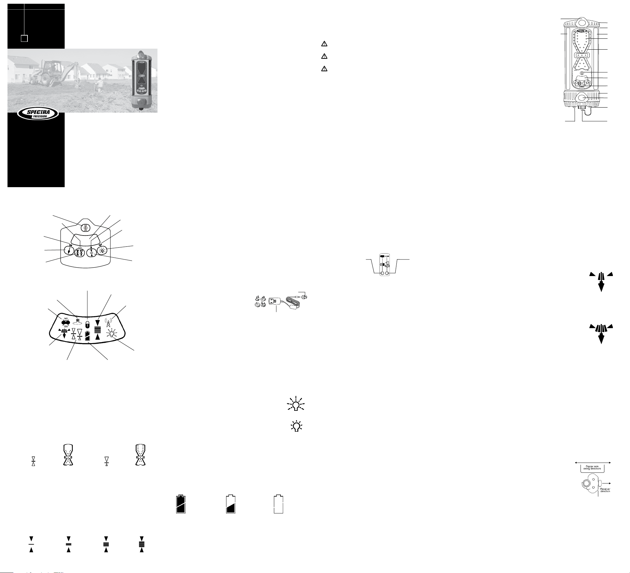
Features and Functions
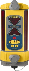
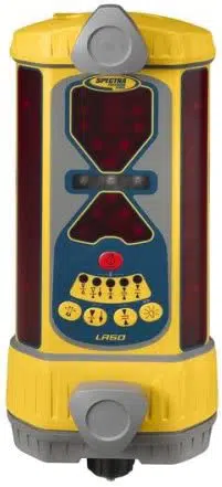
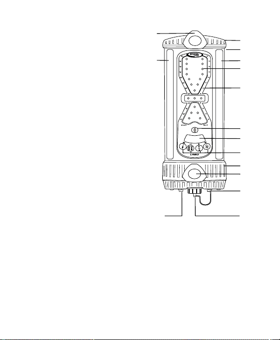
1. Aluminum-Cast Upper and Lower
Housings—protect the receiver.
2. Polycarbonate Housing—protects the
electronics.
3. Receiving Windows—include four sets of
photocell that are equally spaced to allow for
360 degree reception.
4. Ultra-Bright LEDs—are highly visible and
graphically display blade or bucket position.
The green on-grade LEDs and red off-grade
LEDs provide quick visual indication.
5. Setup Length Scale—is used for initial setup
in wide Angle Compensation for Excavation
(ACE) mode.
6. Power Button—turns the receiver on and
off. It also acts as a “shift” key for secondary
receiver functions.
7. Liquid Crystal Display—indicates the
current receiver settings and battery status.
8. Touch-Panel Buttons—allow the settings to be adjusted
9. Mounting Knobs—are attached to stainless steel clamps that allow for quick and
easy installation to the mast or magnetic mount.
10. Access Screws—allow easy access to battery compartment so the batteries can be
replaced.
11. Accessory Connector—accepts the cable to the optional remote display, machine
power cable, or automatic control box. The connector also accepts Ni-MH battery
charger. A dust cap covers the connector to help keep it clean.
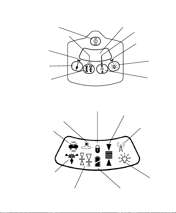
Touch-Panel Lock
Out of Level,
RPM Indication
Beam Averaging
Indication
Display
Brightness
Indication
Deadband
(Accuracy)
Indication
Center or Offset
On-Grade
Indication
Plumb Indication–
Standard,
Wide (ACE), Off
Battery-Status
Indication
Communication
Radio Link
LCD
Display Bright
Display Dim
Installing and Recharging the Batteries
Alkaline Batteries
1. Hold the receiver so the accessory connector is pointing up.
2. Remove the dust cap from the accessory connector.
3. Loosen the two thumb screws and remove the battery access cover.
4. Install four “C” cell alkaline batteries as shown on the label diagram inside the
battery compartment noting the (+) and (–) terminals.
5. Replace the battery access cover. Firmly tighten the two thumbscrews.
6. Replace the accessory connector dust cap.
Nickel Metal Hydride Batteries (Ni-MH)
Rechargeable batteries require an initial and subsequent charging time of
approximately 3 hours. Two or three charging cycles may be required to obtain
maximum battery life. To charge:
1. Remove the dust cap from the accessory connector.
2. Insert the cannon adapter into the receiver
accessory connector aligning the slot and
connector key. Insert the charger female barrel
into the cannon adapter.
3. Make sure the proper AC prongs are on the charger.
Note: To change the prong adapter, press the tab release in the direction indicated
by the arrow and remove the existing prong. Insert the proper adapter and release
the tab.
4. Plug the charger into an appropriate outlet. The receiver will not operate when it
is charging.
Note: The charge-status indicator located on the back of the housing remains
solid when the batteries are charging. The left LED flashes when the batteries are
fully charged.
5. When the batteries are charged, unplug the charger from the outlet, and remove
the cannon adapter from the accessory connector. Replace the dust cap.
Deadband (Accuracy) Button
Four deadbands are available in the grading and excavating modes. The LCD indicates
which mode is selected. Two deadbands (fine and standard) are available in the Angle
Compensation for Excavation (ACE) mode. The smallest deadband is used for receiver
setup. Selections are then made to fit job requirements. For specific deadbands, please
refer to the “Specifications” section of this guide. To change the deadband, press the
deadband button. The deadband and corresponding LCD symbol change and cycle
with each press.
Offset
On-grade
selected
Center
On-grade
LEDs
Center
On-grade
selected
Offset
On-grade
LEDs
Setup WideFine Standard
Additional Features
Battery-Status Indication
A battery-status symbol is depicted on the LCD when the receiver is powered by
batteries. Three levels are displayed. The battery symbol is full when the batteries are
good. The battery symbol is half full and blinking when the batteries are low. The
receiver will still operate for a short period of time. When there is an outline only, the
batteries are drained and must be replaced. The battery symbol outline and the four
corner LEDs flash to indicate the batteries need to be replaced or charged.
Battery
Status-
Low
Battery
Status-
Replace
Battery
Status-
Good
Charge Status Indicator: The LED remains solid when the batteries are charging.
The LED flashes when the batteries are fully charged. When the batteries are charged,
unplug the charger from the outlet, and remove the cannon adapter from the accessory
connector.
Charge Error Indicator: The LED is solid when the internal battery connection has
an error, the batteries are installed incorrectly, the battery type is incorrect, or a battery
cell is dead. A flashing LED indicates that the temperature is too hot/cold to charge.
Charging automatically starts when the temperature is within the above noted range.
Battery Replacement
1. Remove the dust cap, loosen the two thumb screws, and remove the battery-access
cover
2. Remove the old batteries. Install new batteries as previously described. See
“Alkaline Batteries” for more information.
3. Replace the access cover, firmly tighten the two screws, and replace the dust cap.
Note: Refer to your local requirements for proper battery disposal.
Touch Panel
Power Button
Laser
Out-of-Level
Indication
Plumb Button
Center/Offset
On-Grade Button
Deadband
(Accuracy)
Button
Display
Brightness
Button
Communication Link
LCD
Beam Averaging
Indication
Touch-Panel Lock
10
9
7
6
5
4
3
2
1
1
9
11
10
3
8
Cannon Adapter
Charger
Charge Status Indicator
Solid – Charging
Flashing – Charging Complete
Charge Error Indicator
Solid – Battery Problems
Flashing – Temperature Out-of-Limits
(Located on lower rear of polycarbonate housing)

– 2 –
– 5 –
– 9 –
– 3 – – 4 –
– 6 –
– 10 –
– 7 –
– 11 –
– 8 –
– 12 –
LR60 & LR60W
Laser Receiver
User Guide
•
Introduction
Thank you for choosing the Spectra Precision
®
Laser Receiver LR60. The laser receiver
is a rugged, multi-purpose, electronic sensor that detects laser light generated by
rotating laser transmitters. The receiver works with nearly all models of rotating lasers
and detects both visible and invisible beams.
Before using the receiver, be sure to read this user guide carefully. Included in it is
information about setting up, using, and maintaining the receiver. Also included
in this manual are WARNINGS!, CAUTIONS, and Notes. Each of these words
represents a level of danger or concern. A WARNING! indicates a hazard or unsafe
practice that could result in serious injury or death. A CAUTION indicates a hazard or
unsafe practice that could result in minor injury or property damage. A Note indicates
important information unrelated to safety.
Your comments and suggestions are welcome; please contact us at:
Trimble - Spectra Precision Division
5475 Kellenburger Road
Dayton, Ohio 45424-1099 U.S.A.
Phone: (937) 245-5600 / (800) 538-7800
Fax: (937) 233-9004
NOTE: The LR60W ships configured to wireless (Radio) communication mode
for use with a RD20 remote display. Wireless operation is indicated by the
Communications Radio Link symbol on the LCD. To change to wired (RS-485)
mode for use with a control box, simultaneously press the power, deadband and
display brightness buttons (make sure the receiver is powered up first). Pressing this
3-button combination will toggle the receiver between wireless (Radio) and wired (RS-
485) modes as indicated by the following:
Radio Mode Indication: The two outer on-grade LEDs double-blink every few seconds
Wired (RS-485) Mode Indication: The center on-grade LED double-blinks every few
seconds
Once configured the receiver will remember it’s setting after a power cycle. For
additional wireless RD20 operating features please see the RD20 User Guide.
Safety
Please follow all operating and safety instructions in this guide and that of your
machinery. Perform periodic checks of the product’s performance. Trimble or its
representatives assume no responsibility for results of the use of this product including
any direct, indirect, consequential damage, and loss of profits. Check your work
frequently.
WARNING: When working near construction or agricultural machinery, follow
all safety precautions as described in the machinery’s user guide.
WARNING: When excavating, follow all excavation and trench safety regulations
and practices.
WARNING: Be aware of all overhead obstructions and electrical power lines.
The receiver and mast may be higher than the machinery. Remove when transporting
machinery.
CAUTION: Do not disassemble any part of the receiver other than to replace
batteries. The receiver is to be serviced by authorized Trimble service personnel only.
Maintenance and Care
Your receiver was shipped in a protective carrying case. If the receiver is transported
from job to job inside its protective case and normal instrument precautions are
followed, the receiver will provide many years of service. When storing the receiver,
be sure to store it in its carrying case.
Do not wipe dust or dirt off the receiver with a dry cloth as scratching could occur,
possibly damaging these surfaces. Use only a good quality glass cleaner with a soft
cloth on all external components. If these surfaces have hardened concrete or other
materials on them, take the system to your Authorized Service Center for cleaning.
If the receiver will not be used for more than 30 days, remove the alkaline batteries
from it. Be sure to dispose of all batteries properly. Refer to your state or local
requirements for the disposal information.
Controls and Displays
Battery Safety
Built-in overcharging protection prevents damage to the receiver if it is left on charge
after being fully charged. Charge protection also prevents damage if you accidentally
try to recharge alkaline batteries.
CAUTION: Do not attempt to charge alkaline or other disposable batteries.
Note: The batteries should only be charged when the receiver is between 0 °C to
45 °C (32 °F to 113 °F).
The rechargeable battery electronics include charge status and charge-error indicators
located on the back of the housing.
Using the Receiver
Operation
Power Button
Press the power button. All the LEDs light and then each row lights from top to
bottom. The LCD cycles through its symbols. If the receiver is out of the laser beam,
the center green LED flashes and the LCD lights to confirm power is on. If the
receiver is in a laser beam, a corresponding LED grade display lights.
Plumb Button
This plumb button has three positions: off, standard, and Angle Compensation
for Excavation (ACE) mode. Plumb indication is generally used during excavation
operations.
Press the button once to change between standard plumb mode and
plumb off. The standard plumb mode is preset to a range of ±2.5°.
The LCD does not show a plumb symbol when it is turned off; it
shows the standard plumb indicator when the standard plumb mode
is selected. The grade indication LEDs flash quickly when the mast
and receiver are extended beyond the plumb range and flash slowly when retracted
beyond the range. The display is solid when the mast and receiver are within the
plumb range.
Angle Compensation for Excavation (ACE) Mode
The receiver displays grade information at wide swing angles of
±10° to 30°. To enter this mode, press and hold the plumb button
for approximately 2 seconds. The on-grade location automatically
switches to the center on-grade and the wider plumb angle symbol
appears on the LCD. A single LED or pair of LEDs light. These
LEDs correspond to the setup length that is input using the scale on the front label of
the display area. A setup procedure is required to compensate for the dipper-arm swing
arc. To determine this length and for more installation information, please refer to the
“Installation-General” section of this guide.
Center/Offset On-Grade Button
Center on-grade or “grading mode” is selected when grade information is useful both
above and below on-grade, as with typical grading operations. Offset on-grade or
“excavator mode” is selected when using a backhoe or excavator. The excavator mode
gives more information and a larger display above on-grade.
Press the button to cycle between the two options. The LCD indicates which mode
is selected and the LEDs display the appropriate pattern. The center on-grade has 7
display channels plus 2 out-of-beam indications. The offset on-grade has 8 display
channels plus 2 out-of-beam indications.
Display-Brightness Button
The display-brightness button controls the LED brightness. Options
include Bright and Dim. Use Dim for normal and lower light
conditions and Bright for sunny daytime operation. Dim conserves
battery life by approximately 50%. Press the display-brightness
button to cycle through both options. The selection is indicated on
the LCD. Additionally, if the receiver is out of the laser beam, the
LEDs display a circle with the current setting.
Out-of-Beam Indication
The LED display indicates if the receiver has moved beyond the vertical laser-reception
range. A sequence of LEDs indicates which direction the implement must be moved
to pick up the beam. The out-of-beam indication continues for approximately two
minutes.
Out-of-Beam Indication Disable
The out-of-beam indication can be turned off if desired. Press the two outer buttons
(Plumb and Display Brightness) at the same time to disable. The receiver displays
the out-of-beam LED sequence in reverse order from both top and bottom. When
disabled, the receiver indicates out-of-beam by flashing the center LED. Press the two
outer buttons again to enable the indication. The receiver remembers the out-of-beam
display state at the next power up.
Installation
General
1. Set up the laser in a safe and convenient location. For more information about laser
setup, please refer to the laser’s user guide.
Note: Operating distances depend on the rotating laser power. The receiver can
pick up the beam from all directions (360°), but it requires a clear line of sight to
the laser.
2. If your laser has selectable rotation speeds, select a high rotation speed. The receiver
can process speeds up to 1200 RPM.
3. To mount the receiver on the mast, turn both the top and bottom knobs
counterclockwise until the mounting clamps in back open enough to fit around
the mounting mast. Place the receiver on the mast. Turn the knobs clockwise to
tighten.
Note: The receiver will mount to round tubing that has a 42 mm to 50 mm
(1.66 in. to 2.00 in.) outside diameter or to 38 mm (1-1/2 in.) square tubing.
4. To remove the receiver from the mast, loosen the two clamps.
For excavation, the receiver may be set up in the trench or above ground.
Angle Compensation for Excavation (ACE) Mode
The horizontal grade checking width is wider as the receiver setup length is decreased.
For example, the closer the receiver is mounted to the bucket, the wider the grade
checking range will be.
The most accurate and repeatable method for checking grade is with the bucket
cylinder fully retracted. The mast must be mounted so that it points to the bucket
teeth in this setup.
Checking grade with the bucket leveled or in other positions provides for faster rough
excavation. The receiver indicates level at the bucket pivot pin in these positions.
It is important to take grade readings only when the bucket is in the original setup
position.
The LED display must be in the direction of the operator
and be perpendicular to the direction of the dipper arm
swing.
For all excavation operations, always take a sample reading
with the bucket “on-grade” and check to make sure the
elevation is correct.
Features and Functions
1. Aluminum-Cast Upper and Lower
Housings—protect the receiver.
2. Polycarbonate Housing—protects the
electronics.
3. Receiving Windows—include four sets of
photocell that are equally spaced to allow for
360 degree reception.
4. Ultra-Bright LEDs—are highly visible and
graphically display blade or bucket position.
The green on-grade LEDs and red off-grade
LEDs provide quick visual indication.
5. Setup Length Scale—is used for initial setup
in wide Angle Compensation for Excavation
(ACE) mode.
6. Power Button—turns the receiver on and
off. It also acts as a “shift” key for secondary
receiver functions.
7. Liquid Crystal Display—indicates the
current receiver settings and battery status.
8. Touch-Panel Buttons—allow the settings to be adjusted
9. Mounting Knobs—are attached to stainless steel clamps that allow for quick and
easy installation to the mast or magnetic mount.
10. Access Screws—allow easy access to battery compartment so the batteries can be
replaced.
11. Accessory Connector—accepts the cable to the optional remote display, machine
power cable, or automatic control box. The connector also accepts Ni-MH battery
charger. A dust cap covers the connector to help keep it clean.
Touch-Panel Lock
Out of Level,
RPM Indication
Beam Averaging
Indication
Display
Brightness
Indication
Deadband
(Accuracy)
Indication
Center or Offset
On-Grade
Indication
Plumb Indication–
Standard,
Wide (ACE), Off
Battery-Status
Indication
Communication
Radio Link
LCD
Display Bright
Display Dim
Installing and Recharging the Batteries
Alkaline Batteries
1. Hold the receiver so the accessory connector is pointing up.
2. Remove the dust cap from the accessory connector.
3. Loosen the two thumb screws and remove the battery access cover.
4. Install four “C” cell alkaline batteries as shown on the label diagram inside the
battery compartment noting the (+) and (–) terminals.
5. Replace the battery access cover. Firmly tighten the two thumbscrews.
6. Replace the accessory connector dust cap.
Nickel Metal Hydride Batteries (Ni-MH)
Rechargeable batteries require an initial and subsequent charging time of
approximately 3 hours. Two or three charging cycles may be required to obtain
maximum battery life. To charge:
1. Remove the dust cap from the accessory connector.
2. Insert the cannon adapter into the receiver
accessory connector aligning the slot and
connector key. Insert the charger female barrel
into the cannon adapter.
3. Make sure the proper AC prongs are on the charger.
Note: To change the prong adapter, press the tab release in the direction indicated
by the arrow and remove the existing prong. Insert the proper adapter and release
the tab.
4. Plug the charger into an appropriate outlet. The receiver will not operate when it
is charging.
Note: The charge-status indicator located on the back of the housing remains
solid when the batteries are charging. The left LED flashes when the batteries are
fully charged.
5. When the batteries are charged, unplug the charger from the outlet, and remove
the cannon adapter from the accessory connector. Replace the dust cap.
Deadband (Accuracy) Button
Four deadbands are available in the grading and excavating modes. The LCD indicates
which mode is selected. Two deadbands (fine and standard) are available in the Angle
Compensation for Excavation (ACE) mode. The smallest deadband is used for receiver
setup. Selections are then made to fit job requirements. For specific deadbands, please
refer to the “Specifications” section of this guide. To change the deadband, press the
deadband button. The deadband and corresponding LCD symbol change and cycle
with each press.
Offset
On-grade
selected
Center
On-grade
LEDs
Center
On-grade
selected
Offset
On-grade
LEDs
Setup WideFine Standard
Additional Features
Battery-Status Indication
A battery-status symbol is depicted on the LCD when the receiver is powered by
batteries. Three levels are displayed. The battery symbol is full when the batteries are
good. The battery symbol is half full and blinking when the batteries are low. The
receiver will still operate for a short period of time. When there is an outline only, the
batteries are drained and must be replaced. The battery symbol outline and the four
corner LEDs flash to indicate the batteries need to be replaced or charged.
Battery
Status-
Low
Battery
Status-
Replace
Battery
Status-
Good
Charge Status Indicator: The LED remains solid when the batteries are charging.
The LED flashes when the batteries are fully charged. When the batteries are charged,
unplug the charger from the outlet, and remove the cannon adapter from the accessory
connector.
Charge Error Indicator: The LED is solid when the internal battery connection has
an error, the batteries are installed incorrectly, the battery type is incorrect, or a battery
cell is dead. A flashing LED indicates that the temperature is too hot/cold to charge.
Charging automatically starts when the temperature is within the above noted range.
Battery Replacement
1. Remove the dust cap, loosen the two thumb screws, and remove the battery-access
cover
2. Remove the old batteries. Install new batteries as previously described. See
“Alkaline Batteries” for more information.
3. Replace the access cover, firmly tighten the two screws, and replace the dust cap.
Note: Refer to your local requirements for proper battery disposal.
Touch Panel
Power Button
Laser
Out-of-Level
Indication
Plumb Button
Center/Offset
On-Grade Button
Deadband
(Accuracy)
Button
Display
Brightness
Button
Communication Link
LCD
Beam Averaging
Indication
Touch-Panel Lock
10
9
7
6
5
4
3
2
1
1
9
11
10
3
8
Cannon Adapter
Charger
Charge Status Indicator
Solid – Charging
Flashing – Charging Complete
Charge Error Indicator
Solid – Battery Problems
Flashing – Temperature Out-of-Limits
(Located on lower rear of polycarbonate housing)
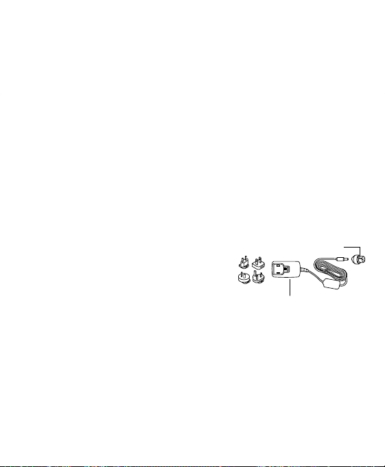
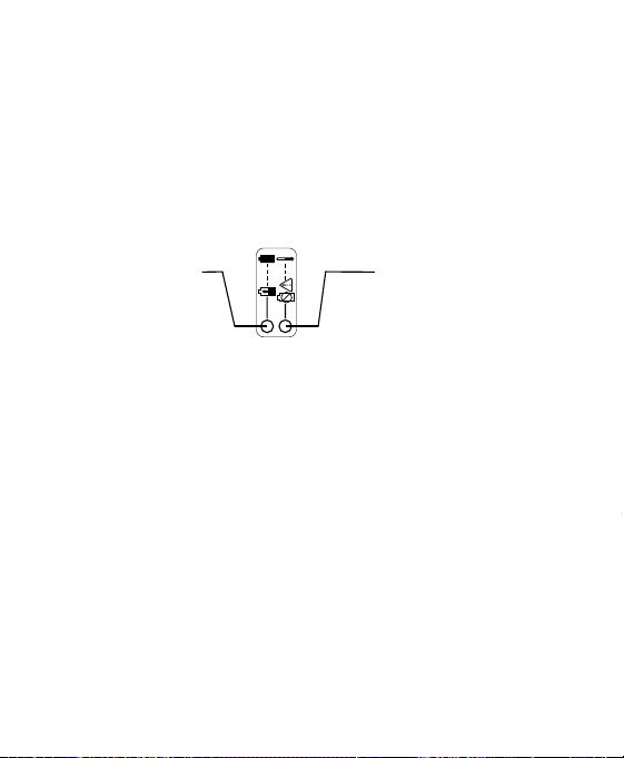
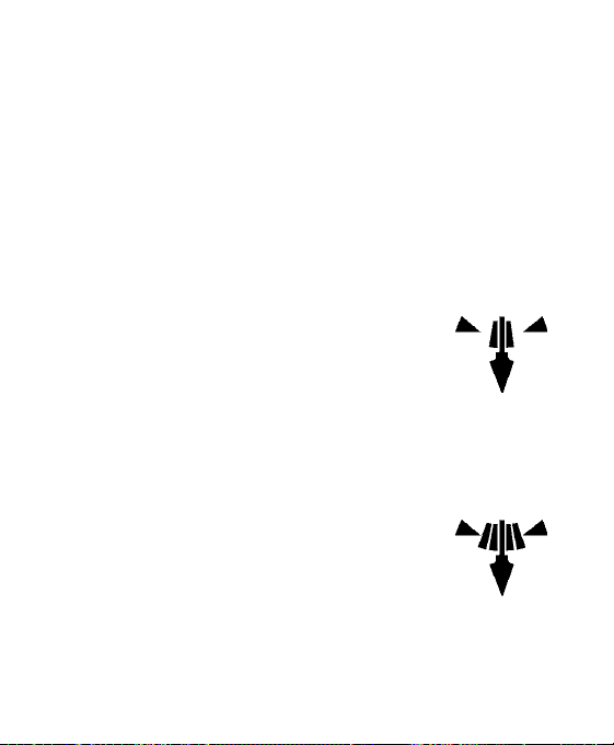
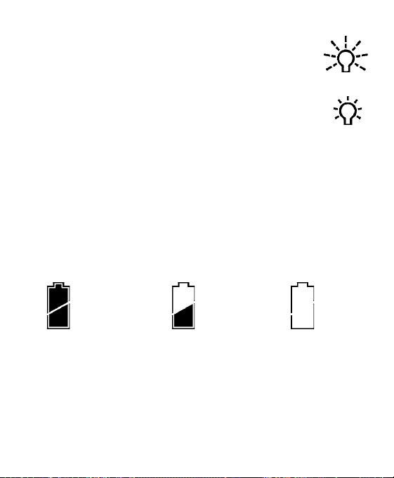
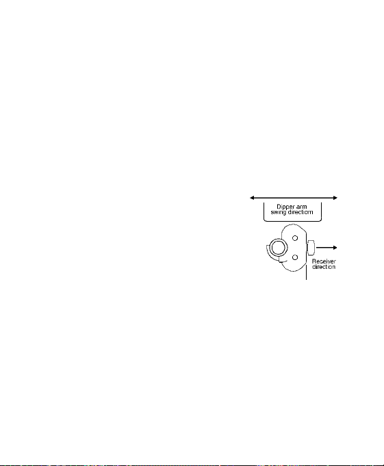
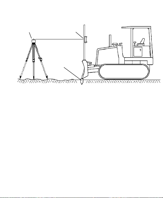
– 13 – – 14 – – 15 – – 16 –
–
17 – – 18 –
– 19 – – 20 –
– 21 – – 22 – – 23 –
Grading
In-Trench Setup – Bucket Leveled
5. Enter the ACE mode.
6. Press and hold the plumb button to scroll up the setup-length scale and release the
button when the lit LED is closest to the measured setup length. The LED flashes
to confirm the setting.
7. Select the desired deadband and begin excavating.
8. Take grade readings with the bucket leveled and LEDs solid.
Out-of-Trench Setup - Bucket Extended
2. Position the receiver so that the setup length (L) is the distance from the bucket
teeth to the offset on-grade symbol on the back of the receiver. (Set up to the
center on-grade symbol if center on-grade will be used).
3. Turn on the receiver, and select standard plumb mode, offset on-grade, and the
desired deadband. (Select center on-grade if set to center symbol).
4. Begin excavating. Take grade readings with the bucket retracted and the LEDs
solid.
ACE mode
1. Follow the Standard Plumb procedures except the setup length is the distance from
the bucket teeth to the center on-grade symbol on the back of the receiver.
2. Enter the ACE mode.
3. Press and hold the plumb button to scroll up the setup-length scale and release
it when the lit LED is closest to the measured setup length. The LED flashes to
confirm the setting.
4. Select the desired deadband and begin excavating.
5. Take grade readings with the bucket retracted and LEDs solid.
Out-of-Trench Setup – Bucket Leveled
1. Level the bucket and position the machine so a measurement can safely be
obtained on the dipper arm.
2. Set up the laser and turn it on.
3. Determine the distance from the laser to the bottom of the trench (L). The length
is the height of the instrument (HI) plus the depth of cut from the benchmark to
the bottom of the trench (C).
Standard Plumb
The standard plumb process is the same irrelevant of whether the bucket is extended
or leveled. For instruction on how to perform this process, please refer to “Out-of-
Trench Setup – Bucket Extended.”
ACE mode
1. Follow the Standard Plumb procedures except the setup length is the finished
elevation to the center on-grade symbol (L) minus the bucket-height length (B).
(Setup length = L - B)
2. Enter the ACE mode.
3. Press and hold the plumb button to scroll up the setup-length scale and release the
button when the lit LED is closest to the measured setup length. The LED flashes
to confirm the setting.
4. Select the desired deadband and begin excavating.
5. Take grade readings with the bucket leveled and LEDs solid.
Important Information about Excavating
Note: For all excavation operations, always take a sample reading with the bucket
“on-grade” and check to make sure the elevation is correct.
For all grading operations, make a sample pass with the blade “on-grade” and check to
make sure the elevation is correct.
For extendable dipper arms – if the mast is mounted to the dipper arm section that
moves with the bucket, grade can be checked with the dipper arm extended to any
position. If the mast is mounted to the dipper arm section that does not move with
the bucket, grade can only be checked when the dipper arm is in the exact setup
position.
7. Select the desired deadband and brightness.
Note: The LED grade display indicates which way to move the blade using the
machine’s controls to maintain an on-grade reading.
8. Make a sample pass with the blade “on-grade” and check to make sure the
elevation is correct.
Excavating
Angle Compensation for Excavation (ACE)
1. Use the length determined by the setup procedure.
2. Press and hold the plumb button to enter the ACE mode and the setup length
entry mode.
Note: The on-grade location automatically switches to the center on-grade, and the
wide plumb (ACE) symbol appears on the LCD. A single LED or pair of LEDs
lights and cycles up the scale as the button is held.
3. Release the button when the LEDs are closest to the setup length. An LED flashes
in approximately 2 seconds to confirm the settings.
Example: If the setup measurement is 2.13 meters, release the button between the
2.00-m and 2.50-m marks on the left-side scale. (If the setup length measurement
is 84 inches, release the button when the pair of LEDs is lit between the 80-inch
and 100-inch marks on the right-side scale.)
4. If the setup number is passed, simply continue pressing the button until it cycles
to the correct number again. The number may also be selected by pressing and
releasing the button while in the setup length entry mode. The LEDs change one
increment each time the button is pressed.
5. Release the button to accept the displayed setup length. An LED flashes in
approximately 2 seconds to confirm the settings.
If the setup measurement is an exact number on the scale, use the next higher number
on the scale.
In-Trench Setup - Bucket Extended
4. Slide the receiver up or down until you get an on-grade display.
5. Select the desired deadband and begin excavating.
6. Take grade readings with the bucket retracted and the LEDs solid.
ACE mode
1. Mount the mast on the side of the dipper arm so that it points to the bucket teeth.
2. Turn on the receiver and select standard plumb mode, center on-grade, and the
smallest deadband.
3. Mount the receiver to the mast, adjust the dipper arm to plumb, and slide the
receiver up or down until you get a solid on-grade display.
4. Safely measure the distance from the bucket teeth to the center on-grade mark on
the back of the receiver. This is the setup length.
5. Enter the ACE mode.
6. Press and hold the plumb button to scroll up the setup-length scale and release the
button when the lit LED is closest to the measured setup length. The LED flashes
to confirm the setting.
7. Select the desired deadband and begin excavating.
8. Take grade readings with the bucket fully retracted and LEDs solid.
Secondary Functions
While the receiver is on, press and hold the power button and then press the touch-
panel buttons to activate secondary or “shift” functions that are indicated by the
symbols above the button.
Laser Out of Level
This function is for use with lasers that have the ability to indicate that they are out
of level by changing the RPM of the laser. Two speeds of 140 RPM and 300 RPM are
available as well as out-of-level turned off. Press and hold the power button and then
press the plumb button to cycle through the options of 140 RPM, 300 RPM, and off.
The LCD indicates which speed is selected. “No display” on the LCD indicates out-
of-level is disabled. When the laser RPM drops to the selected laser out-of-level speed,
an “X” symbol appears on the LED grade display and on the LCD symbol.
Touch-Panel Lock
Press and hold the power button and then press the accuracy button to turn the touch-
panel lock function on and off. When the function is on, the lock symbol appears
on the LCD. Buttons cannot be changed and accidental changes from dirt or debris
knocking the buttons are prevented. To make changes to the receiver, turn off the lock
function.
Specifications
Beam Reception Range 360 degrees
Operating Range Over 460 m (1500 ft) radius, depending on laser
Laser RPM Minimum: 105; Maximum: 1200
Vertical Reception 222 mm (8.75 in.)
Accuracy: On-Grade Deadbands
Setup
Fine
Standard
Wide
Grading
5 mm (0.20 in.)
10 mm (0.40 in.)
20 mm (0.80 in.)
40 mm (1.60 in.)
Excavating
6 mm (0.25 in.)
12 mm (0.50 in.)
25 mm (1.0 in.)
50 mm (2.0 in.)
Fine
Standard
ACE—Angle Compensation Mode
12 mm (0.50 in.)
25 mm (1.0 in.)
Plumb Swing Range
Standard
Angle Compensation Mode
± 2.5°
± 10° to ± 30°
Display Output Bright, Dim
Automatic Control Capability Yes, with CB20, CB25 & CB30 Control Boxes
Tilt Display Yes with RD20 Remote Display
Power Options Alkaline – 4 x “C” Cell – Standard
Nickel Metal Hydride – 4 x “C” Cell
Power Cable – 10 –30 V dc
LR60 Battery Life – Alkaline
LR60W Battery Life – Alkaline
(Continuous in beam)
75 hours, Display Dim / 45 hours, Display Bright
35 hours, Display Dim / 25 hours, Display Bright
LR60 Battery Life – Ni-MH
LR60W Battery Life – Ni-MH
(Continuous in beam)
50 hours, Display Dim / 40 hours, Display Bright
25 hours, Display Dim / 20 hours, Display Bright
Battery Recharge Time 3 – 4 hours
Automatic Shut Off 75 minutes with no laser beam
Out of Beam Indication High and Low
Remote Display Option Yes
Dimensions (LxWxD) 394 x 142 x 149 mm (15.50 in. x 5.58 in. x 5.88 in.)
Mounting Pipe
Round Tube(Outside Diameter)
Square Tube
42 mm to 50 mm (1.66 in. to 2.00 in.)
38 mm (1.50 in.)
Operating Temperature –20 °C to +60 °C (–4 °F to 140 °F)
*Specifications subject to change without notice
Warranty
Trimble warrants the receiver to be free of defects in material and workmanship for a
period of two years.
Trimble or its authorized service center will repair or replace, at its option, any
defective part for which notice has been given during the warranty period. If required,
travel and per diem expenses to and from the place where repairs are made will be
charged to the customer at the prevailing rates.
Customers should send the product to the nearest authorized service center for
warranty repairs, freight prepaid. In countries with Trimble subsidiary service centers,
the repaired product will be returned to the customer, freight prepaid.
Any evidence of negligent, abnormal use, accident, or any attempt to repair the
product by other than factory-authorized personnel using Trimble certified or
recommended parts, automatically voids the warranty.
The foregoing states the entire liability of Trimble regarding the purchase and use of its
equipment. Trimble will not be held responsible for any consequential loss or damage
of any kind.
This warranty is in lieu of all other warranties, except as set forth above, including
any implied warranty merchantability of fitness for a particular purpose, are hereby
disclaimed. This warranty is in lieu of all other warranties, expressed or implied.
Laser
Center
On-grade
Finished Elevation
Benchmark
2.50 meter mark
2.00 meter mark
100 inch mark
80 inch mark
Setup length between
80 and 100 inches
Setup length between
2.00 and 2.50 meters
1. Position the machine so the blade can be set to the desired finished elevation
(typically on a benchmark or hub stake).
2. Set up the laser in an appropriate location for receiver visibility and efficient
machine operation. Turn on the laser.
3. Turn on the receiver, select center on-grade (grading mode), and select the smallest
deadband.
4. Mount the receiver to the mast.
5. Slide the receiver up or down until on-grade is indicated. Adjusting the height of
the laser may be necessary.
Note: Alternatively, if the height of instrument (laser beam) to finished elevation
length is known, the receiver can be set by measuring this distance from the cutting
edge of the blade to the center on-grade mark on the back of the receiver label.
6. Face the LED grade display toward the machine and tighten the clamps.
1. Position the machine, and dig to the desired finished elevation.
2. Fully retract the bucket cylinder and place the bucket teeth at the finished
elevation.
3. Set up the laser and turn it on.
Standard Plumb
1. Mount the mast on the side of the dipper arm.
2. Turn on the receiver, and select standard plumb mode, offset on-grade, (center
on-grade may be used), and the smallest deadband.
3. Place the receiver on the mast and adjust the dipper arm so that the receiver is
within the standard plumb range.
1. Fully retract the bucket cylinder and position the machine so that a measurement
can safely be obtained on the dipper arm.
2. Set up the laser and turn it on.
3. Determine the distance from the laser to the bottom of the trench (L). This is the
setup length. The length is the height of the instrument (HI) plus the depth of cut
from the benchmark to the bottom of the trench (C).
Standard Plumb
1. Mount the mast on the side of the dipper arm so that it points to the bucket teeth.
Beam Averaging
Press and hold the power button and then press the on-grade location button to select
and cycle the laser beam averaging function. Selection “Off ” - no display - chooses
adaptive averaging. In this mode the receiver applies the highest level of averaging
appropriate for the laser rotation speed. A selection of one means every beam strike
is processed. Selecting two or four creates a rolling average of every two or four beam
strikes. Averaging stabilizes the LED display in unstable laser setups, such as windy
conditions or over long distances.
Averaging 2 Selected Averaging 4 SelectedNo Averaging Selected
300 RPM
Selected
Laser below
300 RPM
Indicator
140 RPM
Selected
Laser below
140 RPM
Indicator
1. Position the machine, and dig to the desired finished elevation.
2. Level the bucket and place the bottom of the bucket at the finished elevation.
3. Set up the laser and turn it on.
Standard Plumb
The standard plumb process is the same irrelevant of whether the bucket is extended
or leveled. For instruction on how to perform this process, please refer to “In-Trench
Setup – Bucket Extended.”
ACE mode
1. Mount the mast on the side of the dipper arm so that it points to the bucket pivot
pin.
2. Turn on the receiver, and select standard plumb mode, center on-grade, and the
smallest deadband.
3. Mount the receiver to the mast, adjust the dipper arm to plumb, and slide the
receiver up or down until you get a solid on-grade display.
4. Safely measure the distance from the bucket pivot pin to the center on-grade mark
on the back of the receiver. This is the setup length.
Trimble
Spectra Precision Division
5475 Kellenburger Road
Dayton, Ohio 45424-1099
U.S.A.
+1-937-245-5600 Phone
www.trimble.com
© 2005-2013, Trimble Navigation Limited. All rights reserved.
Reorder PN 0312-0460 (04/13)
Laser
Mast pointed to
bucket teeth
ACE
Setup length –
Center ongrade
to bucket teeth
Excavation
Depth
Laser
Excavation
Depth
Mast pointed to
bucket pivot pin
ACE
Setup length –
Center ongrade
to bucket pivot pin
Benchmark
Bucket
Levelled
Excavation
Depth
HI
Mast pointed to
bucket pivot pin
ACE
Setup = L
Length
HI
ACE
Setup = L
Length
Benchmark
Mast pointed to
bucket teeth
Bucket
Extended
Excavation
Depth
Declaration of Conformity
This receiver to which this declaration relates is in conformity with the essential
requirements and other relevant requirements of the Directive 2004/108/EC (EMC),
Directive 2006/95/EC (LVD) and Council Directive 1999/5/EC R&TTE.
Safety: (article 3.1a) BS EN60950-1: 2006/A12:2011
EN 62311:2008
EMC: (article 3.1b) ETSI EN 301 489-1 V1.9.2 (2011-09) in accordance with
the specific requirements of CISPR22 Class A
ETSI EN 301 489-17 V2.1.1 (2009-05)
Spectrum: (article 3.2) ETSI EN 300 328 V1.7.1 (2006-10), EN61000-9-2,
EN61000-9-3, EN61000-9-6, EN61000-9-8
We hereby declare that the equipment specified above conforms to the above Directive(s).
Trimble Navigation Ltd. August 24, 2012
5475 Kellenburger Road
Dayton, OH 45424-1099 U.S.A.
Notice to Our European Union Customers
For product recycling instructions and more information,
please go to: www
.trimble.com/environment/summary.html
Recycling in Europe
To recycle Trimble WEEE, call: +31 497 53 2430, and ask for the WEEE
associate, or
mail a request for recycling instructions to:
Trimble Europe BV
c/o Menlo Worldwide Logistics
Meerheide 45
5521 DZ Eersel, NL
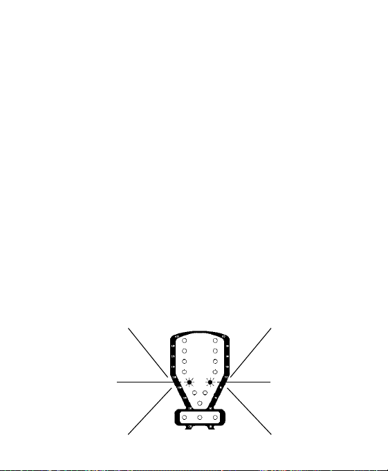
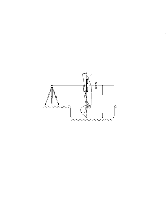
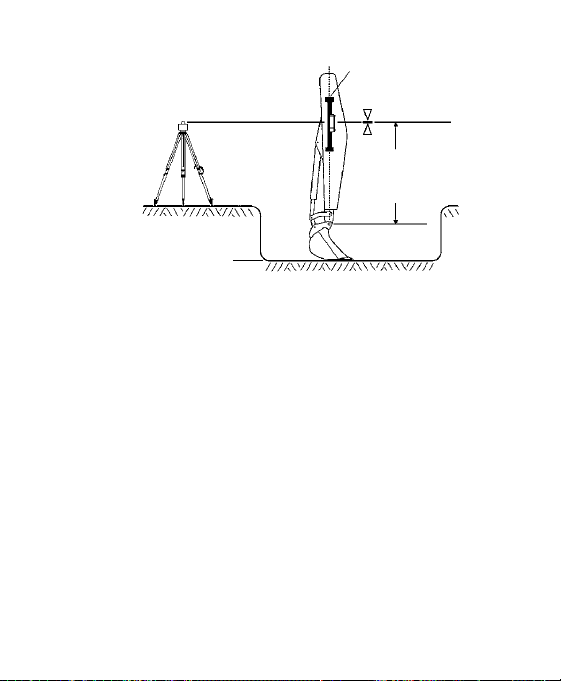
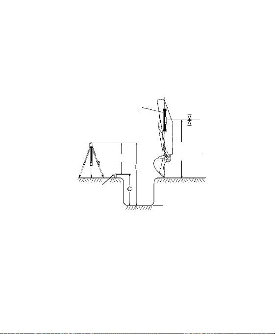
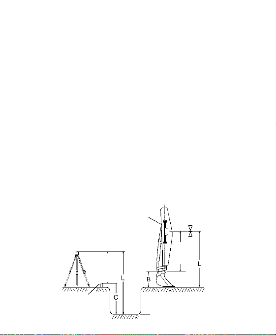
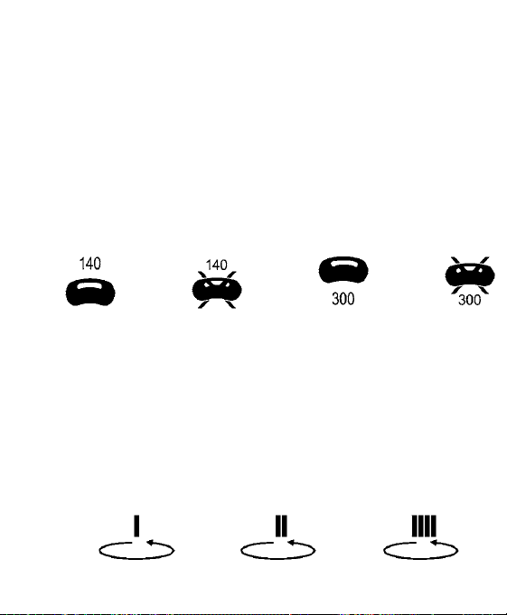