
Loading ...
Loading ...
Loading ...
www.SereneLifeHome.com2
www.SereneLifeHome.com6 www.SereneLifeHome.com 7
PART LIST
INSTALLATION
1. As shown in Fig. B, x Grill Guard (#16) by the Screw (#15).
2. As shown in Fig. A, put Lower Tube (#8) through the hole of Base Cover (#9) and
Base (#10) making sure the end of Lower Tube with welded plate is downward,
and the extra tongue is located in the sink of the base. Fix Lower Tube and Base
together with Washer (#11) & L Screw (#12).
3. Install Middle Tube (#7) on top of Lower Tube. Pullout Straight Tube (#3) upward
from inside of Upper Tube (#5). Screw Outer Fastener (#4) clockwise to lock it.
Then install Upper Tube (#5) on Middle Tube (#7).
4. Turn Outer Fastener counter-clockwise and adjust the unit to a desired height.
Turning it clockwise to x it.
5. Insert Straight Tube into the hole on bottom of Control Box (#1).
Then x them together with Screw (#2).
6. Clip Power Cord (#14) with Cord Clips (#13). Fix them onto the tubes.
7. As shown in Fig. C, the tilting of the heater is adjustable for 25º. Adjust it to a
desired angle when necessary.
OPERATIONS:
1. Plug in the unit to a socket. Make sure the power supply is same as rated.
The blue indicator light starts ashing, which means it's in standby status.
2. Press button "On" on the control panel or the remote controller to switch on
the heater. Then the blue indicator lights up.
3. To switch o the heater, press the button "O" on the control panel of the heater.
If pressing the "O" button on the control panel of the heater, the blue indicator
light is o, and the remote control is not functional. Pressing "O" button on the
remote control will only shift the appliance into standby status, and the blue
indicator light stars ashing again.
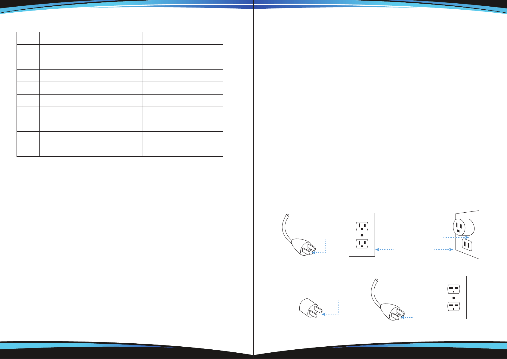
GROUNDING INSTRUCTIONS:
This heater is for use on 120 volts. The cord has a plug as shown at A in Figure
below. An adapter as shown at C is available for connecting three-blade grounding-
type plugs to two-slot receptacles. The green grounding lug extending from the
adapter must be connected to a permanent ground such as a properly grounded
outlet box. The adapter should not be used if a three-slot grounded receptacle is
available.
No. Part Name No. Part Name
1 Control Box 10 Base
2 Screw M6*12 11 Washer
3 Straight Tube 12 L Screw
4 Outer Fastener 13 Cord Clip
5 Upper Tube 14 Power Cord
6 Screw M6*12 15 Grill Guard
7 Middle Tube 16 Tapping Screw ST3*10
8 Lower Tube
9 Base Cover
Grounding Methods
Metal Screw
Ground cover
Outlet Box
Grounding Pin
A B
Grounding Pin
Grounding Means
C D
ADAPTER
Loading ...