
Loading ...
Loading ...
Loading ...
Electrical Shock Hazard
• Electrical ground is required on this appliance.
• Do not connect to the electrical supply until
appliance is permanently grounded.
• Disconnect power to the circuit breaker or fuse
box before making the electrical connection.
• This appliance must be connected to a
grounded, metallic, permanent wiring system,
or a grounding connector should be connected
to the grounding terminal or wire lead on the
appliance.
Failure to do any of the above could result in a
fire, personal injury or electrical shock.
2. Remove the 3 loose nuts (after you remove the
rubber band) on the terminal block using 3/8" nut
driver or socket.
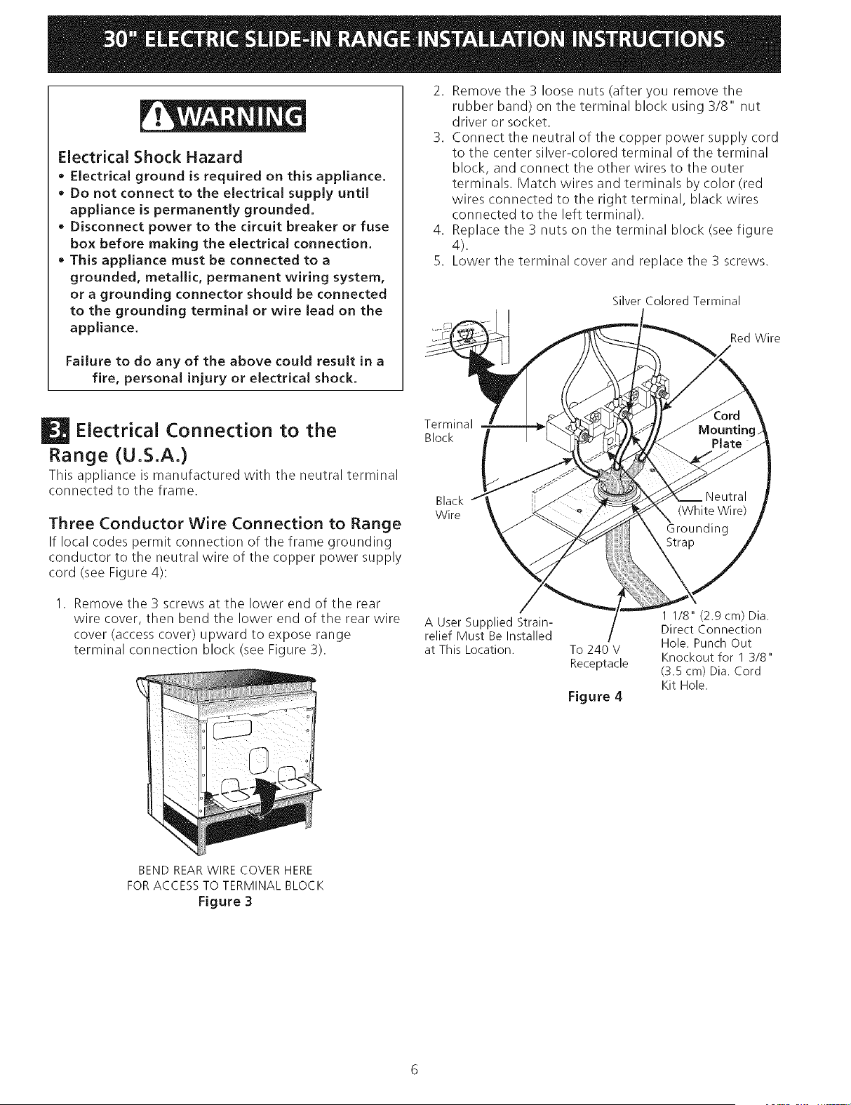
3. Connect the neutral of the copper power supply cord
to the center silver-colored terminal of the terminal
block, and connect the other wires to the outer
terminals. Match wires and terminals by color (red
wires connected to the right terminal, black wires
connected to the left terminal).
4. Replace the 3 nuts on the terminal block (see figure
4).
5. Lower the terminal cover and replace the 3 screws.
Silver Colored Terminal
Red Wire
Electrical Connection to the
Range (U.S.A.)
This appliance is manufactured with the neutral terminal
connected to the frame.
Three Conductor Wire Connection to Range
If local codes permit connection of the frame grounding
conductor to the neutral wire of the copper power supply
cord (see Figure 4):
Remove the 3 screws at the lower end of the rear
wire cover, then bend the lower end of the rear wire
cover (access cover) upward to expose range
terminal connection block (see Figure 3).
Terminal
Block
Black
Wire
A User Supplied Strain-
relief Must Be Installed
at This Location. To 240 V
Receptacle
Figure 4
1 1/8" (2.9 cm) Dia.
Direct Connection
Hole. Punch Out
Knockout for 1 3/8"
(3.5 cm) Dia. Cord
Kit Hole.
BEND REAR WIRE COVER HERE
FOR ACCESS TO TERMINAL BLOCK
Figure 3
Loading ...
Loading ...
Loading ...