Loading ...
2
O/B Terminal Switch Selection
The O/B switch on this thermostat is factory set to “O” position.
This will accommodate the majority of heat pump applications,
which require the changeover relay to be energized in COOL. If the
thermostat you are replacing or the heat pump being installed with
this thermostat requires a “B” terminal, to energize the changeover
relay in HEAT, the O/B switch must be moved to the “B” position.
Attach Thermostat Base to Wall
1. Remove the packing material from the thermostat. Gently
pull the cover straight off the base. Forcing or prying on the
thermostat will cause damage to the unit.
2. Connect wires beneath terminal screws on base using ap-
propriate wiring schematic (see figs. 2 through 4).
3. Place base over hole in wall and mark mounting hole locations
on wall using base as a template.
4. Move base out of the way. Drill mounting holes.
5. Fasten base loosely to wall, as shown in fig. 1, using two
mounting screws. Place a level against bottom of base, adjust
until level, and then tighten screws. (Leveling is for appear-
ance only and will not affect thermostat operation.) If you are
using existing mounting holes, or if holes drilled are too large
and do not allow you to tighten base snugly, use plastic screw
anchors to secure subbase.
6. Push excess wire into wall and plug hole with a fire-resistant
material (such as fiberglass insulation) to prevent drafts from
affecting thermostat operation.
Battery Location
This thermostat does not require batteries to operate. The 2
“AAA” alkaline batteries are for the thermostat to remember the
programming if AC voltage is lost. If the display shows BATT or
when AC power is not present, the batteries are
low and should be replaced with fresh “AAA” alkaline batteries.
For best results, replace all batteries with new premium brand
alkaline batteries such as Duracell
®
or Energizer
®
. To replace the
batteries, install the batteries along the top of the base (see fig.
1). The batteries must be installed with the positive (+) ends to
the right.
4
MOUNTING AND WIRING
Take care when securing and routing wires so they do
not short to adjacent terminals or rear of thermostat.
Personal injury and/or property damage may occur.
CAUTION
!
ATTENTION! This product does not contain mercury. However,
this product may replace a unit which contains mercury.
Do not open mercury cells. If a cell becomes damaged, do not
touch any spilled mercury. Wearing non-absorbent gloves, take
up the spilled mercury and place into a container which can be
sealed. If a cell becomes damaged, the unit should be discarded.
Mercury must not be discarded in household trash. When the unit
this product is replacing is to be discarded, place in a suitable
shipping container. Refer to www.white-rodgers.com for location
to send the product with mercury.
3
REMOVING OLD THERMOSTAT
CONTINUED FROM FIRST PAGE
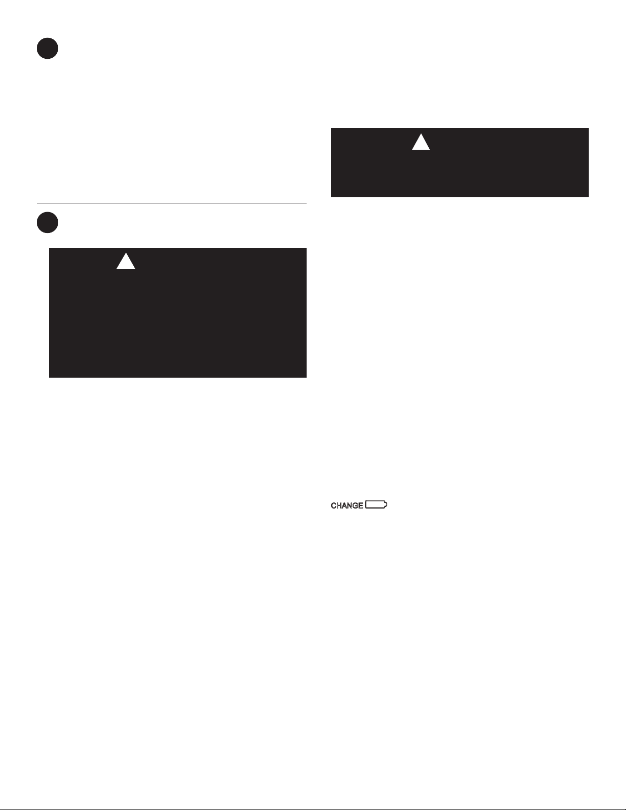
WARNING
!
Electric/Gas Jumper (Fan Option)
If your emergency or auxiliary system will energize the blow-
er, then jumper W906 on the thermostat base must be cut
(see fig. 1).
If your emergency or auxiliary heat system requires that the ther-
mostat energize the fan circuit, do not cut jumper W906.
If you are unsure of your application, contact a qualified
serviceperson.
°F or °C Selection
The factory default setting for temperature display is Fahrenheit.
If you want the temperature in Celsius, clip jumper W904.
Fast or Slow Cycle Selection
The factory default setting is fast cycle, which cycles 1st stage
at approximately 1.2°F and 2nd stage 0.75°F. If you prefer slow
cycle, clip jump W905. The 1st stage and 2nd stage would be
1.5°F and 1.2°F respectively.
Energy Management Recovery (EMR)
This thermostat is set to operate with EMR. This causes the
thermostat to start the heating or cooling system early to have
the room temperature reach the program setpoint at the time the
period is to start.
To disable EMR, clip jumper W903 (see Fig. 1).
Do not use on circuits exceeding specified voltage.
Higher voltage will damage control and could cause
shock or fire hazard.
Do not short out terminals on gas valve or primary control
to test. Short or incorrect wiring will damage thermostat
and could cause personal injury and/or property damage.
Thermostat installation and all components of the sys-
tem shall conform to Class II circuits per the NEC code.
Loading ...
Loading ...
Loading ...