
Loading ...
MODEL RDH
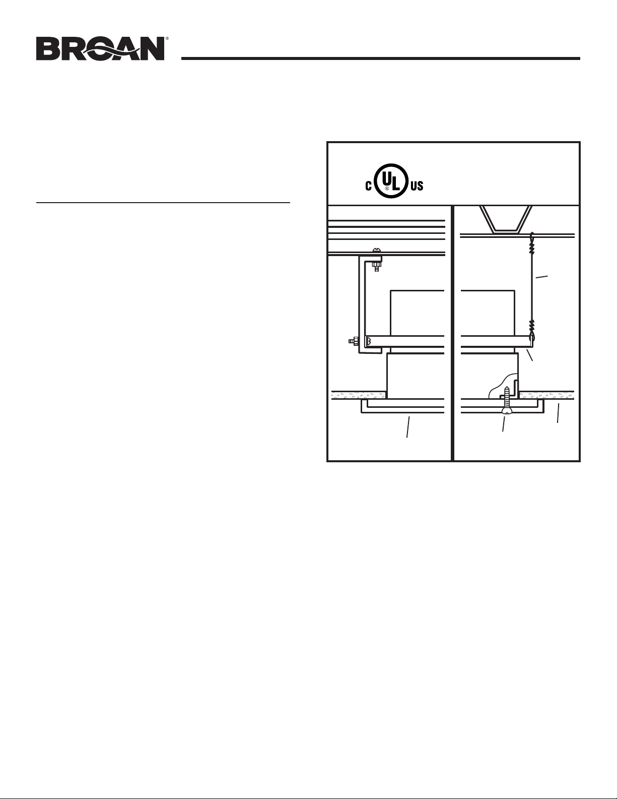
Page 2
NON-COMBUSTIBLE
FLOOR / CEILING
INSTALLATION
1. Plan installation so that ceiling penetration is located
within ceiling tiles or panels without necessitating cuts
in any ceiling suspension main runners or cross tees.
Ifrequired, a maximum of one runner or cross tee
may be cut to accommodate desired damper location.
Cutends must be supported by a minimum 12 gauge
(3mm) steel, vertical hanger wire.
2. Mount fan/damper assembly to the deck or ceiling
structure above or adjacent to the assembly. If the
assembly is hung from the structure above, a minimum
12 gauge (3mm) steel, hanger wire must be used. There
must be a minimum of two wires on each of two opposite
sides. If the assembly is directly mounted to the adjacent
structure, use #8 (M4) sheet metal screws or 1/4”
(6mm) diameter bolts with nuts (hardware not provided)
to mechanically fasten it to the structure. Position fan/
damper assembly so that the inlet face of the radiation
damper is flush with the finished surface of the ceiling.
Ceiling opening must be no larger than the inlet opening
of the damper.
3. New Construction
A housing mask has been provided to keep construction
dust, drywall spray, paint, etc. from damaging the
radiation damper or blower assembly.
a) Bend up the small tab of the mask.
b) Tuck the opposite side of the mask under one of the
damper’s grille mounting ears and push mask up into
damper housing.
Remove mask before installing grille or operating fan.
4. Attach the metal grille over the inlet face of the radiation
damper using (2) #8-18 x 0.812” sheet metal screws
(provided).
CLASSIFIED
SEE DETAILS ON UL
CLASSIFICATION
MARKING ON
PRODUCT
FAN
GRILLE
WIRE
DAMPER
GRILLE
SCREW
CEILING
MOUNTING
BRACKET
Loading ...
Loading ...
Loading ...