9.800-504.0 - G 01/15/21
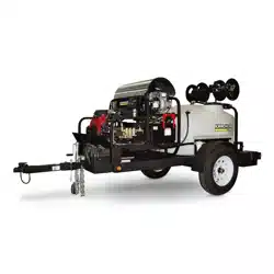
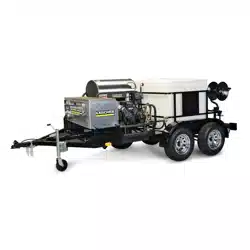
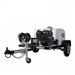
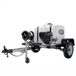
SMT Series
Hot Water - Electric Start - Diesel
English 02
To locate your local Kärcher
Commercial Pressure Washer
Dealer nearest you, visit
www.karchercommercial.com
2
Model Number: _____________________________________________
Serial Number: ______________________________________________
Date of Purchase: ____________________________________________
The model and serial numbers will be found on a decal attached to the
pressure washer. Record both serial number and date of purchase.
MODEL: SMT-354037E 1.103-841.0
PATENT PENDING
Kärcher SMT Operator’s Manual 9.800-504.0 - G
Introduction
Thank you for purchasing this Pressure Washer. We reserve the right to make changes at any time
without incurring any obligation.
Owner/User Responsibility:
The owner and/or user must have an understanding of the manufacturer’s operating instructions and
warnings before using this pressure washer. Warning information should be emphasized and
understood. If the operator is not fluent in English, the manufacturer’s instructions and warnings
shall be read to and discussed with the operator in the operator’s native language by the
purchaser/owner, making sure that the operator comprehends its contents. Owner and/or user must
study and maintain for future reference the manufacturers’ instructions.
Save These Instructions
This manual should be considered a permanent part of the machine and should remain with it if
machine is resold. When ordering parts, please specify model and serial number. Use only identical
replacement parts.This machine is to be used only by trained operators.
Notice
This trailer is equipped to meet applicable U.S. Federal safety standards. Check local and state
requirements regarding brakes and any additional equipment that may be required. Any modifications
or additions including load equalizing hitches, without written factory consent: usage in an
abnormal manner including overloading voids all manufacturers’ warranties and liability.
WARNING: This Owner's Manual contains safety information and instructions for your trailer. You
must read this manual before loading or towing your trailer.
You must follow all safety precautions and instructions.

3
Machine Data Label . . . . . . . . . . . . . . . . . . . . . . . . . .2
Table of Contents . . . . . . . . . . . . . . . . . . . . . . . . . . .3
Important Safety Information. . . . . . . . . . . . . . . . . . . 4
Reporting Safety Defects . . . . . . . . . . . . . . . . . . . . .6
Checklist . . . . . . . . . . . . . . . . . . . . . . . . . . . . . . . . . . 6
Important Trailer Safety Information . . . . . . . . . . . .7
Tire Safety. . . . . . . . . . . . . . . . . . . . . . . . . . . . . . . . . 7
Understanding Tire Pressure and Load Limits . . . . .7
Tow Vehicles. . . . . . . . . . . . . . . . . . . . . . . . . . . . . . .9
Safety Chains . . . . . . . . . . . . . . . . . . . . . . . . . . . . .10
Load-Carrying Capacity . . . . . . . . . . . . . . . . . . . . . 10
Proper Weight Distribution & Tongue Weight . . . . .11
Tongue Weight . . . . . . . . . . . . . . . . . . . . . . . . . . . .11
Caster Operations . . . . . . . . . . . . . . . . . . . . . . . . . . 12
Trailer Brake Operations. . . . . . . . . . . . . . . . . . . . .13
What to Check And How To Check . . . . . . . . . . . .14
Tire Pressure . . . . . . . . . . . . . . . . . . . . . . . . . . . . .14
Wheels . . . . . . . . . . . . . . . . . . . . . . . . . . . . . . . . . . 14
Ball Coupler Hitches . . . . . . . . . . . . . . . . . . . . . . . .14
Tires . . . . . . . . . . . . . . . . . . . . . . . . . . . . . . . . . . . .14
Trailer Component Identification . . . . . . . . . . . . . . .15
Accessory Assembly Instructions . . . . . . . . . . . . . .16
Assembly Instructions . . . . . . . . . . . . . . . . . . . . . . .17
Installation. . . . . . . . . . . . . . . . . . . . . . . . . . . . . . . . 18
Operating Instructions. . . . . . . . . . . . . . . . . . . . . . . 19
Detergents & General
Operating Techniques. . . . . . . . . . . . . . . . . . . . . 20
Cleaning Tips . . . . . . . . . . . . . . . . . . . . . . . . . . . . . 20
Shutting Down And
Clean-Up . . . . . . . . . . . . . . . . . . . . . . . . . . . . . . . 21
Rinsing . . . . . . . . . . . . . . . . . . . . . . . . . . . . . . . . . . 21
Storage . . . . . . . . . . . . . . . . . . . . . . . . . . . . . . . . . .22
Preventative Maintenance . . . . . . . . . . . . . . . . . . .23
Maintenance And Service . . . . . . . . . . . . . . . . . . . .23
Unloader Valves . . . . . . . . . . . . . . . . . . . . . . . . . . .23
Winterizing Procedure. . . . . . . . . . . . . . . . . . . . . . .23
High Limit Hot Water Thermostat . . . . . . . . . . . . . .23
Pumps . . . . . . . . . . . . . . . . . . . . . . . . . . . . . . . . . . .23
Cleaning of Coils. . . . . . . . . . . . . . . . . . . . . . . . . . .23
Fuel . . . . . . . . . . . . . . . . . . . . . . . . . . . . . . . . . . . . .24
Burner Nozzle . . . . . . . . . . . . . . . . . . . . . . . . . . . . .24
Oil Burner . . . . . . . . . . . . . . . . . . . . . . . . . . . . . . . .24
Electrode Setting. . . . . . . . . . . . . . . . . . . . . . . . . . .25
Fuel Pressure Adjustment. . . . . . . . . . . . . . . . . . . .25
Removal of Soot and Heating Coil . . . . . . . . . . . . .25
Hub Inspection Removal-
Replacement And Adjustments. . . . . . . . . . . . . .26
Torque Wrench Method . . . . . . . . . . . . . . . . . . . . .27
Posi-lube Lubrication Procedure . . . . . . . . . . . . . . .27
Troubleshooting . . . . . . . . . . . . . . . . . . . . . . . . . . .28
Pressure Washer Preventive Maintenance. . . . . . .30
Maintenance Schedule . . . . . . . . . . . . . . . . . . . . . .30
Trailer Maintenance Schedule . . . . . . . . . . . . . . . .31
Pump And Engine Oil Change Record . . . . . . . . . .31
Kärcher SMT Operator’s Manual 9.800-504.0 - G
4
Important Safety Information
WARNING: To reduce the risk of
injury, read operating instruc-
tions carefully before using.
AVERTISSEMENT: Pour réduire
le risque de blessures, lire
attentivement les instructions
de fonctionnement avant l'utili-
sation.
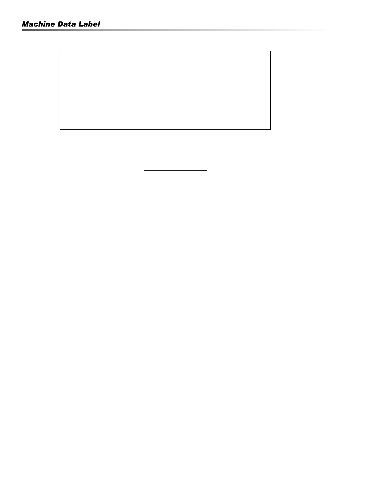
1.Read the owner's manual thor-
oughly. Failure to follow instruc-
tions could cause malfunction of the machine and
result in death, serious bodily injury and/or property
damage.
2. Know how to stop the machine and bleed pressure
quickly. Be thoroughly familiar with the controls.
3. Stay alert — watch what you are doing.
DANGER: Keep wand, hose, and
water spray away from electric
wiring or fatal electric shock
may result.
AVERTISSEMENT: Garder la
lance, le boyau et le jet d'eau à
l'écart de tout câblage
électrique ou des chocs
électriques mortels pourraient
survenir.
4. To protect the operator from electrical shock, the
machine must be electrically grounded.
WARNING: Flammable liquids
can create fumes which can
ignite, causing property damage
or severe injury.
AVERTISSEMENT: Des liquides
inflammables peuvent produire
des vapeurs qui peuvent
s'enflammer, causant ainsi des
dommages à la propriété ou des
blessures graves
WARNING: Risk of explosion — Operate only
where open flame or torch is permitted.
AVERTISSEMENT: Risque d'explosion - Utiliser
uniquement dans des endroits où l'utilisation d'une
flamme nue ou d'une torche est permise.
5. In oil burning models, use only kerosene, No. 1
home heating fuel, or diesel. If diesel is used, add a
soot remover to every tankful.
WARNING: Risk of fire — Do
not add fuel when the product
is operating or still hot.
AVERTISSEMENT: Risque
d'incendie - Ne pas ajouter de
carburant pendant que la
machine fonctionner ou est
encore chaude.
WARNING: Do not use gasoline
crankcase draining or oil
containing gasoline, solvents or alcohol. Doing so
will result in fire and/or explosion.
AVERTISSEMENT: Ne pas utiliser d'essence, de
drainage du carter de moteur ou d'essence
contenant de l'huile, de solvants ou de l'alcool.
Agir de la sorte risquerait de créer un incendie et/
ou une explosion.
6. Operate only in locations where combustible dusts
and flammable gases or vapors are not present.
Do not store or use gasoline near this machine.
7. Do not allow acids, caustic or abrasive fluids to
pass through the pump.
8. Never run pump dry or leave spray gun closed
longer than 1-2 minutes.
9. Keep operating area clear of all persons.
WARNING: High pressure spray
can cause paint chips or other
particles to become airborne
and fly at high speeds. To avoid
personal injury, eye, hand and
foot safety devices must be
worn.
AVERTISSEMENT: Un jet haute
pression peut écailler la
peinture ou provoquer
l'émission d'autres particules dans l'air et leur
projection à hautes vitesses. Pour éviter les
lésions corporelles, une protection des yeux, du
visage, des mains et des pieds doit être portée lors
de l'utilisation de cet équipement.
10. Always wear properly rated eye protection such as
safety goggles or face shield while spraying.
(Safety glasses do not provide full protection.)
Kärcher SMT Operator’s Manual 9.800-504.0 - G
5
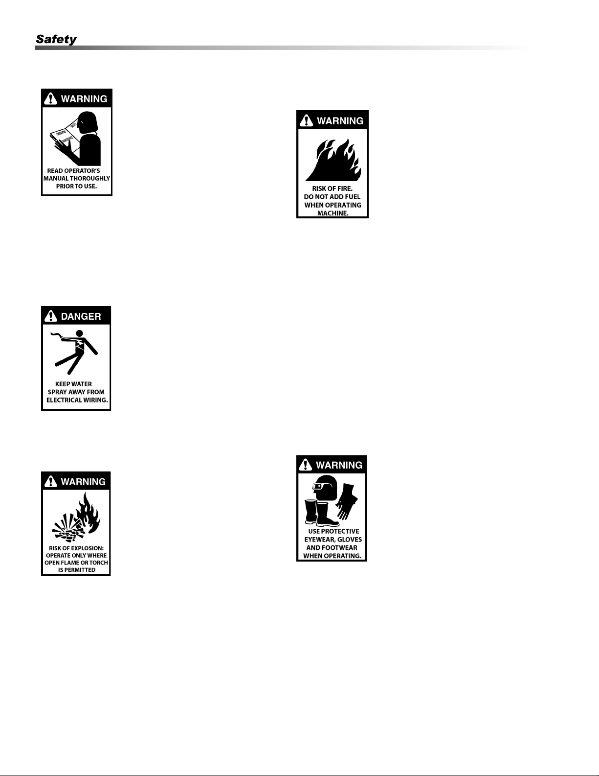
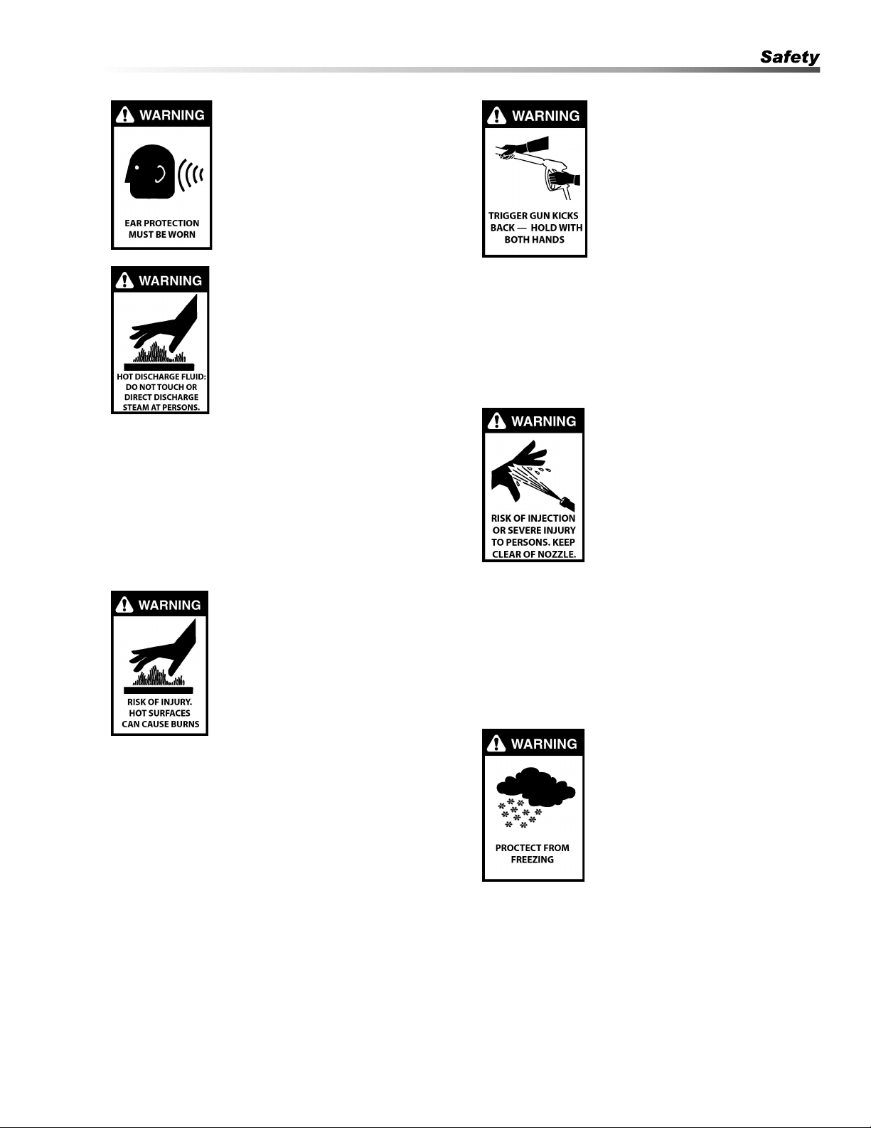
WARNING: This machine
exceeds 85 dB. Appropriate ear
protection must be worn.
AVERTISSEMENT: Cette
machine excède 85 dB et une
protection de l'ouïe appropriée
doit être portée.
WARNING: Hot discharge fluid.
Do not touch or direct discharge
stream at persons or animals.
AVERTISSEMENT: Liquide de
décharge chaud. Ne pas toucher
ou décharger directement le jet
vers des personnes ou des
animaux, car cela risquerait de
causer des blessures graves ou
même la mort.
WARNING: This machine produces hot water and
must have insulated components attached to
protect the operator.
AVERTISSEMENT: Cette machine produit de l'eau
chaude et doit comporter des composants isolés
attachés pour protéger l'opérateur.
WARNING: Risk of injury. Hot
surfaces can cause burns. Use
only designated gripping areas
of spray gun and wand. Do not
place hands or feet on non-
insulated areas of the pressure
washer.
AVERTISSEMENT: Risque de
blessures. Les surfaces chaudes
peuvent causer des brûlures.
Utiliser uniquement les zones de prise désignées
du pistolet pulvérisateur et de la lance. Utiliser
uniquement les zones de prise désignées du
pistolet pulvérisateur et de la lance.
11. To reduce the risk of injury, close supervision is
necessary when a machine is used near children.
Do not allow children to operate the pressure
washer. This machine must be attended during
operation.
WARNING: Grip cleaning wand
securely with both hands
before starting. Failure to do
this could result in injury from a
whipping wand.
AVERTISSEMENT: Agripper la
lance de nettoyage avec les
deux mains avant de
commencer. Le non-respect de
cette consigne pourrait mener à
des blessures causées par le
mouvement violent de la lance.
12. Never make adjustments on machine while in
operation.
13. Be certain all quick coupler fittings are secured
before using pressure washer.
WARNING: High pressure
developed by these machines
will cause personal injury or
equipment damage. Keep clear
of nozzle. Use caution when
operating. Do not direct
discharge stream at people or
animals, or severe injury or
death will result.
AVERTISSEMENT: La haute
pression générée par ces machines causera des
lésions corporelles ou des dommages à
l'équipement. Ne pas décharger directement le jet
vers des personnes ou des animaux, car cela
risquerait de causer des blessures graves ou
même la mort Se tenir à l'écart de la buse. Faire
preuve de prudence lors de l'utilisation.
WARNING: Protect machine
from freezing.
AVERTISSEMENT: Protéger la
machine contre le gel.
14.To keep machine in best
operating conditions, it is
important you protect machine
from freezing. Failure to protect
machine from freezing could
cause malfunction of the machine
and result in death, serious bodily injury, and/or
property damage. Follow storage instructions
specified in this manual.
Kärcher SMT Operator’s Manual 9.800-504.0 - G
6
15. Running this product indoors can result in death
due to carbon monoxide, a poison gas you cannot
see or smell. Never operate indoors, even if
windows and doors are open. Only use outdoor
and far away from windows, doors, and openings
or vents.
16. Manufacturer will not be liable for any changes
made to our standard machines or any compo-
nents not purchased from us.
17. The best insurance against an accident is
precaution and knowledge of the machine.
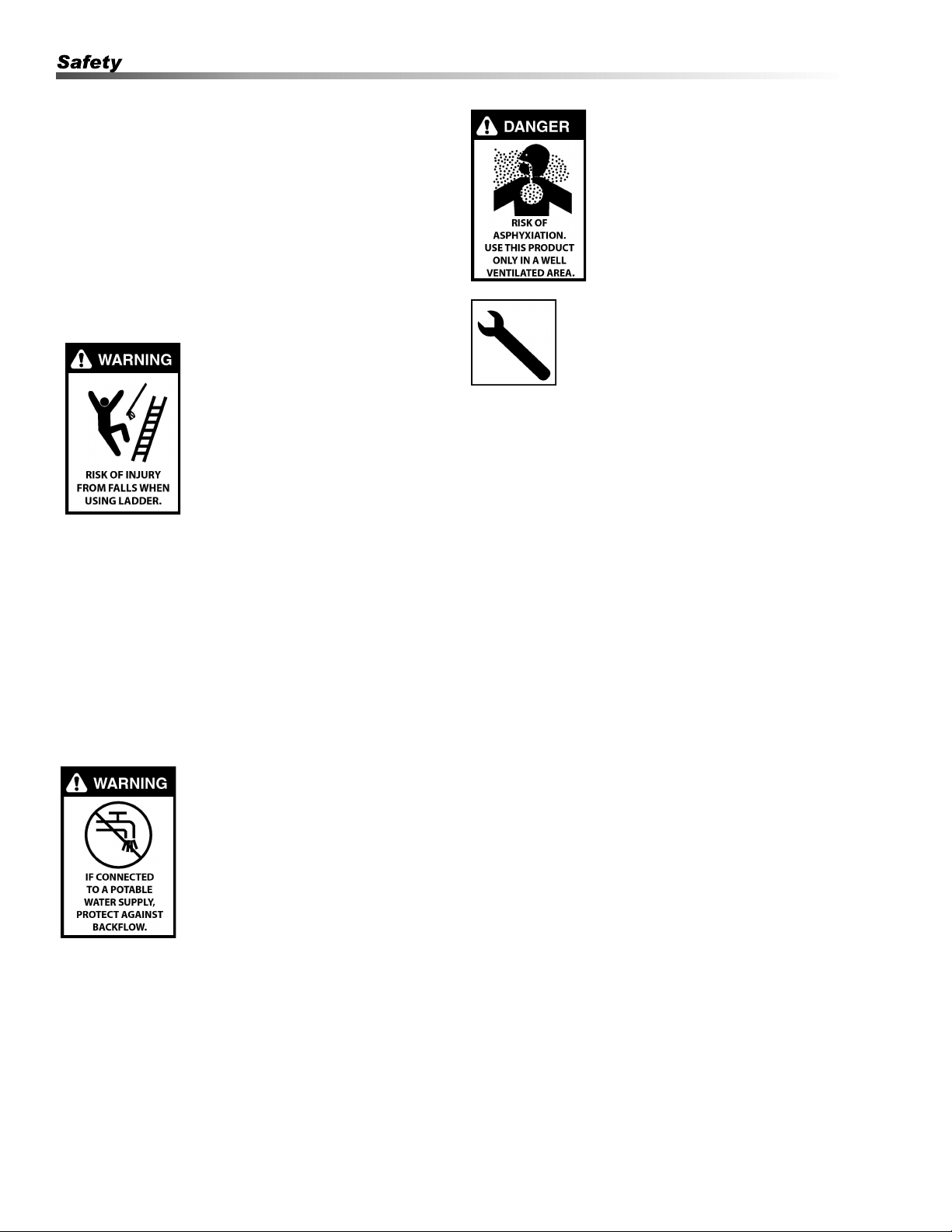
WARNING: Be extremely
careful when using a ladder,
scaffolding or any other rela-
tively unstable location. The
cleaning area should have
adequate slopes and drainage
to reduce the possibility of a fall
due to slippery surfaces.
AVERTISSEMENT: Faire preuve
d'une extrême prudence au
moment d'utiliser une échelle, des échafaudages
ou toute autre surface relativement instable. La
zone de nettoyage doit avoir une pente et un
drainage adéquats pour réduire la possibilité d'une
chute due à une surface glissante.
18. Do not overreach or stand on unstable support.
Keep good footing and balance at all times.
19. Do not operate this machine when fatigued or
under the influence of alcohol, prescription medica-
tions, or drugs.
WARNING: If connection is made
to a potable water system, the
system shall be protected
against backflow.
AVERTISSEMENT: Si une
connexion est établie avec un
réseau d'eau potable, le réseau
doit être protégé contre le retour
d'eau.
20. Inlet water must be clean fresh water and no hotter
then 90°F.
21. Before disconnecting discharge hose from water
outlet, turn burner off and open spray gun to allow
water to cool below 100° before stopping the
machine. Then open the spray gun to relieve
pressure. Failure to properly cool down or maintain
the heating coil may result in a steam explosion.
DANGER: Risk of asphyxiation.
Use this product only in a well
ventilated area.
DANGER: Risque d'asphyxie.
Utiliser ce produit uniquement
dans un endroit bien ventilé.
Follow the maintenance
instructions specified in the
manual.
Suivre les instructions d'entretien
spécifiées dans le manuel.
Reporting Safety Defects
If you believe that your trailer has a defect which could
cause a crash or could cause injury or death, you
should immediately inform the National Highway Traffic
Safety Administration (NHTSA) in addition to notifying
Kärcher.
If NHTSA receives similar complaints, it may open an
investigation, and if it finds that a safety defect exists in
a group of trailers, it may order a recall and remedy
campaign. However, NHTSA cannot become involved
in individual problems between you, your dealer or
Kärcher.
To contact NHTSA, you may either call the Auto Safety
Hotline toll-free at 1-888-327-4236 (TTY: 1-800-424-
9153) or write to:
NHTSA
1200 New Jersey Avenue, SE
West building
Washington, DC 20590
You can also obtain other information about motor
vehicle safety from, http://www.safecar.gov.
Checklist
Before Every Trip:
• Tire pressure and tire condition
• Wheel lugs*
• Bearing lube and tightness
• Hitch
• Safety chains
• 12V running lights
• Distribution and security
• Caster up in travel position
Kärcher SMT Operator’s Manual 9.800-504.0 - G

7
* Check lug nuts for tightness before initial trip, at 10
miles, 25 miles and 50 miles. Recheck every 3 months
or 3000 miles.
NOTE: Checking all of the above steps before every
trip is key for safety.
Referencing the Utility Trailer in this
Manual
All references to the trailer or component parts to either
left or right are made with the assumption that you are
standing behind the trailer facing forward. Your left
hand or right hand is the equivalent on the trailer.
Tire Safety
The most common cause of trailer tire failure is under-
inflation. Therefore, it is important that you always
maintain the specified air pressure as indicated by the
tire manufacturer on the tire's side-walls. This informa-
tion can also be found on the tire label or the air
pressure molded on the tire side-wall.
The most important things you can do to maintaining
proper tire pressure are observe all tire and trailer
maximum carrying capacities, avoid road hazards, and
inspect the tires for cuts, slashes and other irregulari-
ties. These practices, along with other care and mainte-
nance, can improve handling, help protect you and
others from avoidable breakdowns and accidents,
improve fuel economy, and increase the life of your
tires.
Make tire safety a regular part of your trailer mainte-
nance routine. The time you spend is minimal
compared to the amount of time, inconvenience, and
potential safety hazards that can occur from a flat tire or
failure.
Basic Tire Maintenance
Properly maintained tires improve the load-carrying
capability of your trailer. You can help avoid flat tires
and tire failures by maintaining proper tire pressure,
observing tire and trailer capacity limits, avoiding road
hazards, and inspecting your tires regularly.
Identifying Your Recommended Tire
Pressure and Maximum Load Carrying
Capacity for Your Trailer
Both the tire placard and the VIN label are permanently
attached on top of the frame of your trailer and have the
required information printed on them. They also list the
maximum load that can be placed on the trailer without
exceeding the load limits of the tires or the trailers other
components. These labels indicate the manufacturer’s
information including:
• Recommended tire size.
• Recommended tire inflation pressure.
• The maximum weight the trailer is designed to
carry.
• Gross vehicle weight rating of the trailer.
• Gross axle weight rating of the trailer.
Understanding Tire Pressure and Load
Limits
Tire inflation pressure is the level of air in the tire that
provides it with the load-carrying capacity and affects
the overall performance of the trailer. The tire inflation
pressure is a number that indicates the amount of air
pressure that is inside the tire. It is measured in pounds
per square inch (PSI). The tire must be inflated to the
air pressure as designated on the labels. Also listed on
the labels is the air pressure in kilo Pascals (kPa),
which is a metric measurement. Tire manufacturers
determine the air pressure to maximize the amount of
weight the tires can safely carry. The proper tire
pressure for your trailer tires is referred to as the
"recommended cold inflation pressure." It is difficult to
obtain the recommended tire pressure if your tires are
not cold when the reading is taken because the air will
expand when it is warmed by towing down the road,
thus increasing the air pressure inside. If air is added to
a tire that is low the air pressure should never exceed
the recommended pressure.
It is important to check your trailer’s tire pressure at
least once a month for the following reasons:
Most tires will naturally lose air over time.
Tires can lose air suddenly if driven over an object that
punctures or cuts the tire. Sometimes a sharp blow
from a pothole or curb can knock the tire loose from the
rim causing immediate deflation.
Kärcher SMT Operator’s Manual 9.800-504.0 - G

8
Maintaining Proper Tire Pressure
Locate the recommended tire pressure on the trailer's
tire information placard or owner's manual.
Record the tire pressure of all tires. If the tire pressure
is too high in any of the tires, slowly release air by
gently pressing on the tire valve stem with the edge of
your tire gauge until you get the correct pressure.
If the tire pressure is too low, note the difference
between the measured tire pressure and the correct tire
pressure. These "missing" pounds of pressure are what
you will need to add.
Add the missing pounds of air pressure to each tire that
is under inflated.
Check all tires to make sure they have the same air
pressure.
If you have been towing your trailer and think that a tire
is under inflated, fill it to the recommended cold inflation
pressure indicated on your trailer's tire label placard or
the VIN label. You can also check the sidewall of the
tire for a correct tire inflation pressure. Your tire will
have a slightly lower air pressure because the tire is
warm when you are inflating it, but it will be much better
than to continue to tow it with the under inflation it may
have had. Once the trailer has been parked long
enough to allow the tires to cool down, recheck the tire
pressure and add additional air to return the tire
pressure to the recommended level.
Tire Size
To maintain the trailer's carrying capacity and safety,
purchase only the same size tires as what were origi-
nally supplied on the trailer.
Safety Tips
Slow down if you have to go over a pothole or other
object in road.
Do not run over curbs and try not to strike the curb
when parking.
For a free brochure visit:
www.nhtsa.dot.gov
IMPORTANT: Before towing this trailer be sure to
read the instructions and warnings supplied in this
manual. Also read the information supplied with
your tow vehicle so you know and understand it's
limitations.
Never Tow the Trailer Before Checking
• Coupler and latch assembly show no signs of
wear or damage.
• Coupler hitch and hitch ball are of the same
size.
• Coupler and safety chains are safely secured to
the hitch.
• Check all fasteners for proper tightness.
• Load is securely tied down to the trailer.
• Wheel lug nuts are properly tightened to the
right torque.
• Wheel bearings are properly adjusted and
maintained.
• Load is within the maximum load carrying
capacity of trailer.
• Tires are properly inflated and are road worthy.
• All trailer lighting is working properly.
IMPORTANT: The load must be distributed equally
on the bed of the trailer if possible. Heavy, concen-
trated loads may cause damage or possible failure
of the trailer.
WARNING: Loads place on the trailer must be
securely tied to the trailer. Always use appropriate
tie downs designed to restrict loads from moving
when properly attached. Failure to do so will allow
shifting of the load causing potential trailer failure
and/or loss of the load and personal injury.
AVERTISSEMENT: Les charges placées sur la
remorque doivent être solidement attachées à la
remorque. Toujours utiliser des arrimages
appropriés conçus pour empêcher les charges de
bouger lorsqu'elles sont bien attachées. Le non-
respect de cette consigne permettra le mouvement
de la charge, entraînant une défaillance potentielle
de la remorque et/ou une perte de la charge et des
lésions corporelles.
This trailer is equipped to meet all applicable federal
safety standards in effect the day of manufacture.
Check local and state requirements regarding any addi-
tional equipment that may be required.
The addition of optional equipment to your trailer may
in- crease the total weight of your trailer package to
where it now exceeds the maximum load carrying
capacity of the trailer.
Kärcher SMT Operator’s Manual 9.800-504.0 - G

9
Tow Vehicles
WARNING: Serious injury or property damage can
result if the total weight of your loaded trailer
exceeds the capacity of the hitch and/or your tow
vehicle.
AVERTISSEMENT: Des blessures graves ou de
dommages à la propriété peuvent survenir sir le
poids total de la remorque chargée excède la
capacité de l'attelage et/ou du véhicule
remorqueur.
It is very important that you know and understand the
towing capabilities of your tow vehicle. This is espe-
cially true with the braking abilities of the tow vehicle.
You should check with your authorized dealer to see
what the capabilities are for the total towing load and
the maximum allowable tongue weight for the vehicle
you plan on using for towing.
It is also important that the lighting system in the tow
vehicle has sufficient capacity support the additional
load the trailer lighting will add to the system. A heavy
duty flasher may be required to make your turn signals
function properly.
Trailer Ball & Couplers
WARNING: Failure to properly engage the hitch ball
in the coupler ball socket and securely lock the
coupler latch mechanism can cause the trailer to
become detached from the tow vehicle while trav-
eling, which may cause serious injury or property
damage.
AVERTISSEMENT: Le non-respect d'engager
correctement la boule d'attache dans la cavité de la
boule de l'attelage et de verrouiller solidement le
mécanisme du loquet de l'attelage pourrait mener
la remorque à se détacher du véhicule remorqueur
pendant le déplacement, ce qui pourrait causer des
blessures graves ou des dommages à la propriété.
Ball diameter for which rating (GVWR) shall not exceed
the gross trailer weight marked on the trailer coupler.
The hitch balls have the rated load they are capable of
towing stamped Into the top of the ball.
Make sure the ball that you use to tow your trailer has
the same capacity rating as the coupler.
Do not use a different size ball than the size the coupler is
designed to use.
Hitch Coupler Troubleshooting
If the coupler becomes damaged it must be repaired or
replaced before towing. When the coupler is placed on
the ball, the latch should close firmly. Keep the latch
mechanism lightly oiled and clean. Items to check for
are as follows:
1. Latch does not grasp ball securely:
• Check the ball size. Make sure the ball and
coupler are the same size.
2. Latch does not snap into full latch position:
• Check adjustment. Latch mechanism may be
too tight.
• Check to see that the coupler housing has not
been damaged, keeping the ball hitch from
fitting completely into the housing as designed.
3. Keep the tongue blocked up when not in use so the
coupler and mechanism are not in the ground
being exposed to dirt and moisture.
4. Apply a small amount of an automotive grease to
the ball before hitching coupler to prevent wear of
the two parts during towing.
5. Make sure the latch safety pin is in position before
towing.
Coupler & Ball Engagement
If the coupler and towing ball resist attempts to make
engagement, do not force latch assembly. Instead,
check the ball diameter to verify that it conforms to
Society of Automotive Engineers (SAE) specifications.
Standard two-inch diameter ball should be within the
limits of 2.000-inches to 1.970-inches. Balls larger than
2.000- inches will not readily fit the coupler. A two-piece
coupler ball is not recommended.
If the coupler becomes damaged it must be repaired or
replaced before towing. When the coupler is placed on
the ball, the latch should close firmly. Keep the latch
mechanism lightly oiled and clean.
Improper engagement of the coupler and ball can
cause damage if the vehicles separate in transit, thus,
caution must be exercised to insure a secure hook-up.
Lower the coupler onto the ball with the coupler latch in
the vertical position. Continue to lower the trailer
tongue until the jack clears the ground, then flip the
coupler latch to its locked (horizontal) position. At this
point visually observe that the ball is fully engaged in
the ball hitch. An even better check to make sure the
two are fully engaged is to raise the tongue of the trailer
again using the jack. Raise until the ball hitch connec-
tion starts to raise the rear of the tow vehicle. If the
connection was not properly made, the ball and socket
will separate as the tongue of the trailer is raised.
Class Coupler Ball Diameter
II 3,500# GVWR 2”
III 5,000# GVWR 2”
IV 8,000# GVWR 2”
Kärcher SMT Operator’s Manual 9.800-504.0 - G
10
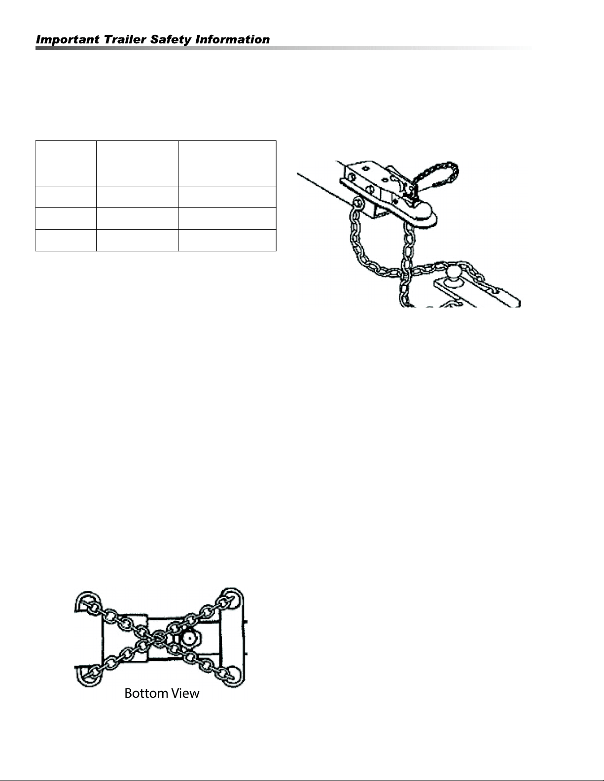
Safety Chains
Listed in the chart below are the different class sizes of
safety chains and the rated load each chain must be
capable of withstanding.
WARNING: Failure to properly attach safety chains
between the trailer and tow vehicle can result in a
runaway trailer.
AVERTISSEMENT: Le non-respect de fixer
correctement les chaînes de sécurité entre la
remorque et le véhicule remorqueur peut mener à
l'emballement de la remorque.
WARNING: To avoid accidents, before trailering:
• Hitch only to ball size marked on coupling.
• Ball clamp must capture ball and lever or hand
wheel is fully clamped.
• Cross safety chains under coupling.
• Allow only enough slack for turns.
AVERTISSEMENT: Pour éviter les accidents avant
de procéder à un remorquage :
• Atteler uniquement à une boule dont la taille
correspond à celle indiquée sur l'attelage.
• La boule de serrage doit capturer la boule et le
levier ou le volant à main est complètement
serré.
• Croiser les chaînes de sécurité sous l'attelage.
• Laisser suffisamment de jeu pour permettre la
rotation libre.
The safety chains on your trailer are an added
insurance that it will not become detached from the tow
vehicle. All safety chains are provided with an added
clasp to keep them from becoming accidentally
detached from the tow vehicle. Your trailer hitch on the
tow vehicle should have two attaching holes or rings for
attaching the safety chains, preferably one on each
side of the ball hitch. Crisscross the chains under the
tongue, the chain on the left side of the trailer tongue
attached to the right side of the ball hitch, the chain on
the right side of the trailer tongue attached to the left
side of the ball hitch.
This prevents the trailer tongue from dropping to the
road should the coupler or ball hitch fail. The chains
should be rigged as tight as possible with just enough
slack to allow tight turns to be made. This can be
accomplished by twisting the chain hook in a clockwise
or counterclockwise direction thus twisting the link
spacing and making the chain shorter. Also by keeping
your chains as short as possible you prevent them from
dragging on the road and wearing the chain links. If for
any reason you find it necessary to replace a safety
chain, use only original equipment.
Load-Carrying Capacity
Located on the front left-hand side of the frame, (either
the inside or the outside) is the VIN (Vehicle Identifica-
tion Number) tag. It will show the GVWR (Gross
Vehicle Weight Rating) which is the maximum load that
can be applied to the tires on the trailer. The GVWR
and the carrying capacity of the trailer are based on the
tire size installed on the trailer.
The GVWR is the maximum carrying capacity of the
trailer with its respective tires. It may not necessarily
equal the total GVWR of the trailer less the empty
weight of the trailer because there may be another
controlling factor such as frame strength that reduces
the carrying capacity to what is listed on the VIN tag.
TRAILER
CLASS
TRAILER
WEIGHT GVWR
IN LBS.
MINIMUM BRAKING
STRENGTH IN LBS.
I to 2,000 2,000
II 2,000 to 3,500 3,500
III 3,500 to 5,000 5,000
Kärcher SMT Operator’s Manual 9.800-504.0 - G
11
The tire label will list the tire size that was installed on
the trailer as original equipment when it was sold to
you, the consumer. It also lists the maximum carrying
capacity of the trailer.
IMPORTANT: The total weight of the load must
never exceed the weight of cargo listed on the tire
label and/or the maximum load carrying capacity
listed on the VIN tag on your trailer. The GVWR
(Gross Vehicle Weight Rating) listed is the
maximum total weight of the trailer with accesso-
ries and all cargo allowable to be carried on the
tires that are installed on the trailer.
WARNING: Fishtailing caused from improper
tongue weight on the tow vehicle hitch ball can
cause loss of control of the tow vehicle and
resulting serious injury or property damage.
AVERTISSEMENT: Une embardée causée par un
poids de l'attelage inapproprié sur la boule
d'attache du véhicule remorqueur peut causer une
perte de contrôle du véhicule remorqueur et causer
des blessures graves et des dommages à la
propriété.
CAUTION: The maximum load applied to the trailer
must never exceed the carrying capacity of the
trailer as stated on the VIN label and/or the tire
placard. Doing so may cause failure of one or more
component parts of the trailer causing potential
damage to the trailer and/ or a potential accident.
All concentrated loads must be spread over as
large an area as possible to eliminate potential
damage to the decking.
ATTENTION: La charge maximale appliquée à la
remorque ne doit jamais excéder la capacité de
charge de la remorque comme mentionné sur
l'étiquette NIV et/ou le flanc du pneu. Agir de la
sorte risquerait de causer une défaillance d'une ou
plusieurs composantes de la remorque, causant
des dommages potentiels à la remorque et/ou un
accident potentiel. Toutes les charges concentrées
doivent être réparties sur une surface aussi large
que possible pour éliminer tout dommage potentiel
au patio.
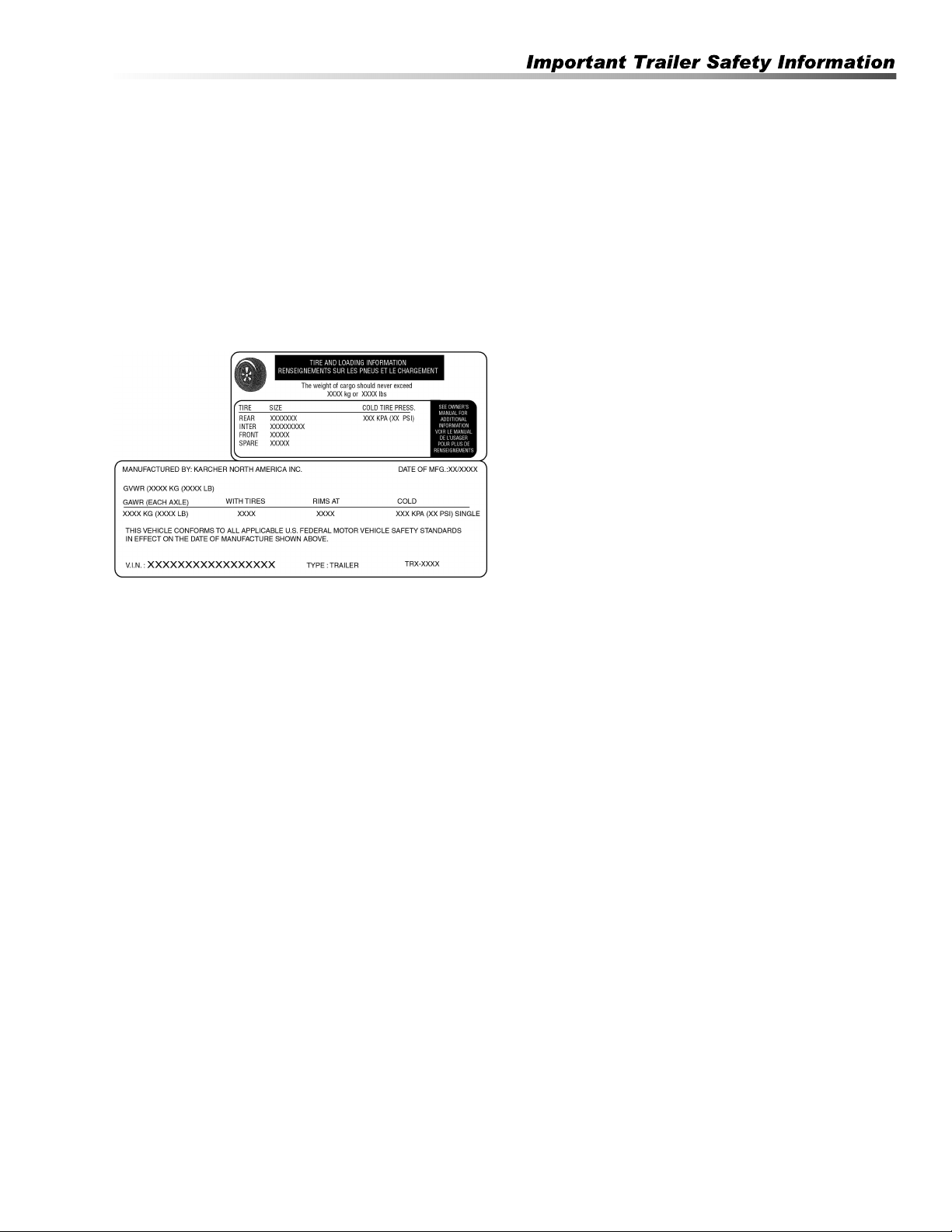
Shown below is an example of the tire label that is
placed on your trailer showing the items just discussed
above. Once you have familiarized yourself with the
information supplied on the example tire label and VIN
tag, check the tire size and capacity of your trailer as
shown on the VIN tag on your trailer.
Proper Weight Distribution & Tongue
Weight
Ensuring that your trailer has the proper GVWR is very
important. Once that has been established and you
have the load on the trailer it is equally important that
you have proper weight distribution.
Tongue Weight
The tongue weight on your trailer is 10%-15% of the
total weight of the trailer and all the cargo that it is
carrying. This is the amount of weight that is then trans-
ferred to the tow vehicle through the ball hitch.
Example: The total weight of the trailer with load is 800
pounds. The tongue weight should not be less than 80
pounds (10%).
Too light of tongue weight can cause the trailer to “fish-
tail” (sway Weight Rating) as you travel down the
highway. This creates excessive strains on the tow
vehicle, hitch and on the trailer itself. It can very easily
lead to an accident.
To adjust for too light of a tongue weight the load must
be shifted for-ward with respect to the axle. This will
increase the weight that is transferred to the tongue.
Adjustments should be made until the tongue weight
falls within 10% -15% recommended range. Likewise, if
you have too much tongue weight adjust the weight
backwards with respect to the axle until the tongue
weight falls in the recommended range
Tow vehicles vary on how much tongue weight they
can support for proper towing.
Kärcher SMT Operator’s Manual 9.800-504.0 - G
12
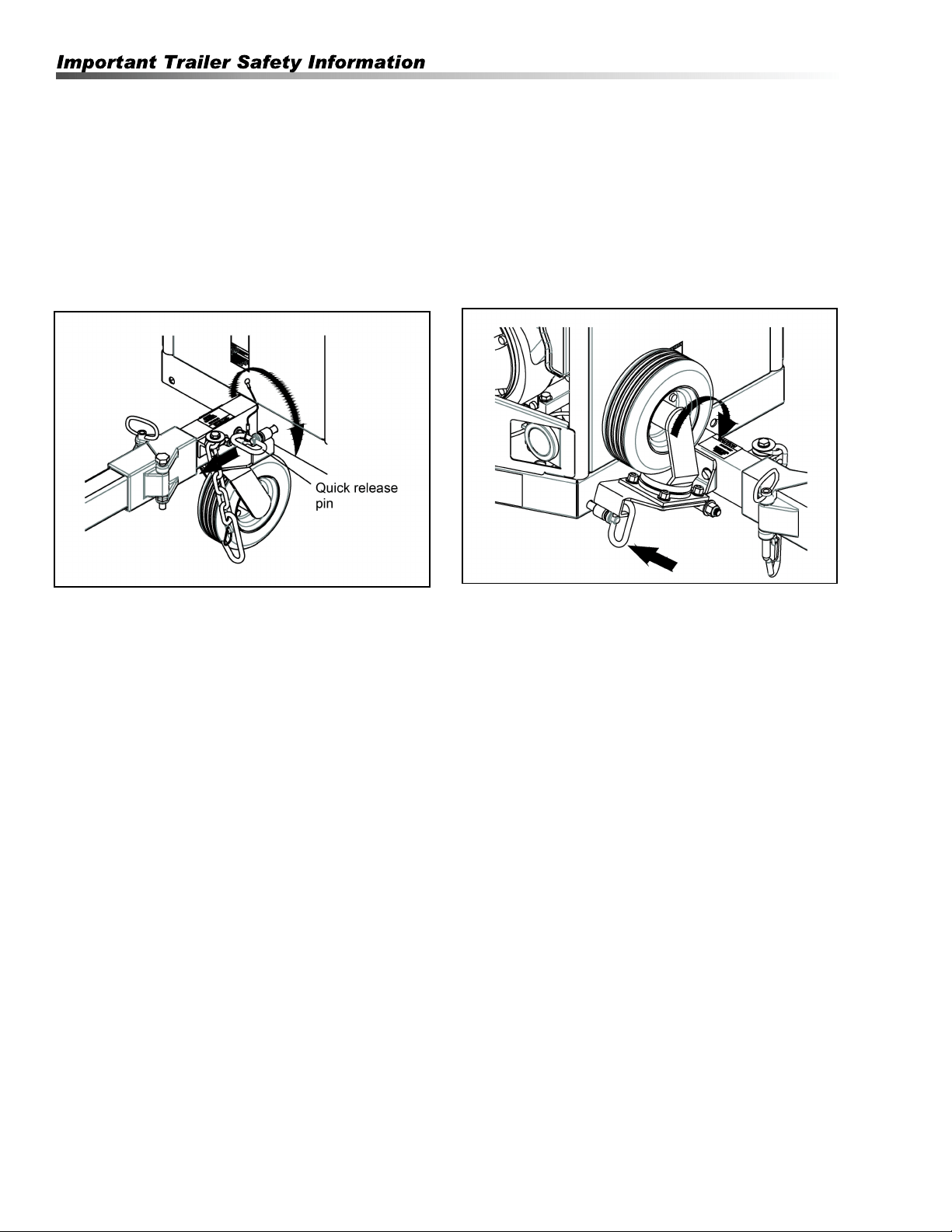
Caster Operations
This trailer has a caster for manual transporting while
using the pressure washer and to keep the trailer
tongue off the ground when not trailering.
WARNING: The caster must be in the up position
when trailering the unit.
AVERTISSEMENT: La roulette doit se trouver en
position verticale lorsque l'appareil est remorqué.
STEP 1: Release the quick release pin by rotating it
clock wise. Pull Quick release pin from receptacle.
Rotate the caster clockwise.
STEP 2: Insert quick release pin in receptacle. Lock
quick release pin in place by rotating pin counter clock-
wise. Reverse step to lower caster.
NOTE: Before towing, diesel shut-off valve must be in
the OFF position.
Kärcher SMT Operator’s Manual 9.800-504.0 - G

13
Trailer Brake Operations
WARNING: To avoid injury, the trailer brake must
be set when operating the pressure washer or
when not in use.
AVERTISSEMENT: Pour éviter les blessures, le
frein de la remorque doit être appliqué lors de
l'utilisation de la laveuse à pression ou lorsqu'elle
n'est pas utilisée.
To set the brake, press down on the brake pedal until it
engages on the back tires.
To release the brake, push the center of the brake to
release see that it has disengaged from the back tire.
CAUTION: This brake has a spring mechanism that
will return brake to its dis-engaged state. Make sure
foot or hand is moved out of the pinch point area.
Ce frein comprend un mécanisme à
ressort qui retournera le frein à sa position de
désengagement. Garder les pieds et les mains à
l'écart de la zone du point de pincement.
Kärcher SMT Operator’s Manual 9.800-504.0 - G
14
Tire Pressure
Proper air pressure for your tires is printed on the
sidewall. Check pressure while tires are cold. Do not
raise or lower pressure to meet load. Pressure other
than recommended pressure will lead to excessive tire
wear or tire failure. Balancing recommended.
Wheels
Check wheels for hole elongation or “out of round”. This
condition can be caused by lug nuts not being tight or
being too tight. Trailer wheels can be damaged by
chuck holes or curb jumping. You may not be aware of
the road shock to the wheels without periodic checks.
Replace any wheel that is bent. Replace any wheel if
you see elongation of the bolt holes.
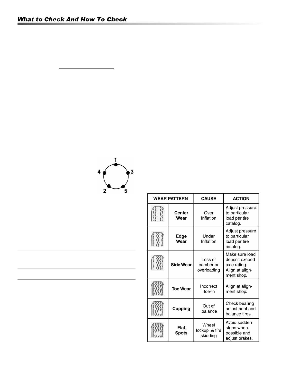
Wheel Lugs
Wheel lug nuts must be tightened with a torque wrench.
Refer to the chart below for proper torque.
1. Start all bolts or nuts by hand to
prevent cross threading.
2. Tighten bolts or nuts following
sequence at right.
3. The tightening of the fasteners
should be done in stages.
Following the recommended sequence, tighten
fasteners per wheel torque chart below.
4. Wheel nuts/bolts should be torqued before first
road use and after each wheel removal. Check and
re-torque after the first 10 miles, 25 miles and
again at 50 miles. Check periodically thereafter.
Wheel Torque Requirements
Ball Coupler Hitches
Coupler assembly includes a latch lever and latch lever
safety pin or hitch pin. Be sure the latch lever is locked
and the pin properly secured before moving your trailer.
The pin can be engaged fully only if ball is properly
seated in the coupler.
Tires
Before mounting tires onto wheels make certain that
the rim size and contour is approved for the tire as
shown in the Tire and Rim Association Yearbook or the
tire manufacturer’s catalog. Also make sure the tire will
carry the rated load. If the load is not equal on all tires
due to trailer weight distribution, use the tire rated for
the heaviest wheel position.
NOTE: The capacity rating molded into the sidewall
of the tire is not always the proper rating for the tire if
used in a trailer application. Use the following
guideline:
1. LT and ST tires: use the capacity rating molded
into the tire.
2. Passenger Car Tires: Use the capacity rating
molded into the tire sidewall divided by 1.10.
Use tire mounting procedures as outlined by the
Rubber Manufacturer’s Association or the tire manufac-
turers.
NOTE: Tire wear should be checked frequently
because once a wear pattern becomes firmly
established in a tire it is difficult to stop, even if
the underlying cause is corrected.
WHEEL
SIZE
TORQUE SEQUENCE
1st Stage 2nd Stage 3rd Stage
16" 20 - 25 50 - 60 80-90
Kärcher SMT Operator’s Manual 9.800-504.0 - G
15
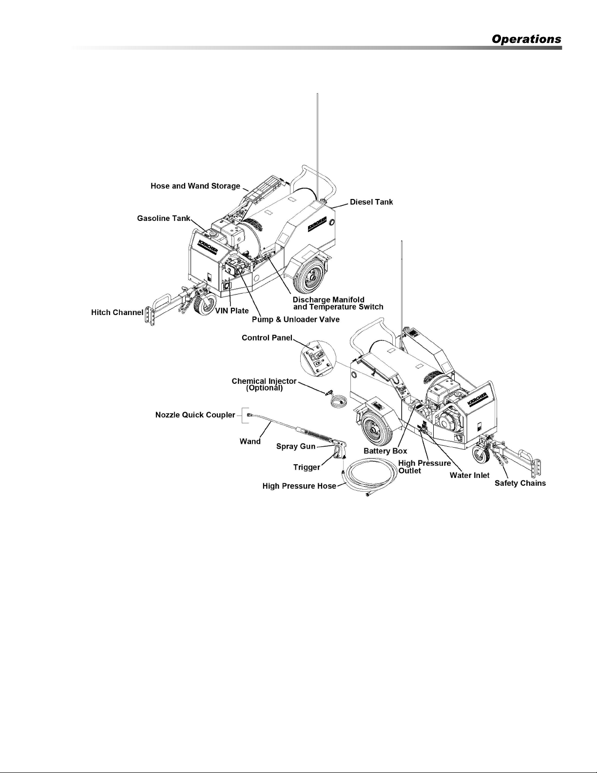
Trailer Component Identification
Pump — Delivers a specific GPM to the high pressure
nozzle which develops pressure.
Spray Gun — Controls the application of water and
detergent onto cleaning surface with trigger device.
Includes safety latch.
Detergent Injector — Allows you to siphon and mix
detergents.
Wand — Must be connected to the spray gun.
High Pressure Hose — Connect one end to water
pump high pressure discharge nipple and the other end
to spray gun.
Rupture Disk— Secondary pressure release in the
unlikely event the unloader valve fails. Not shown.
Unloader Valve — Safety device which, when the
spray gun closes, prevents over pressurization.
NOTE: If trigger on spray gun is released for more
than 2 minutes, water will leak from the pump
protector. Warm water will discharge from pump
protector onto floor. This system prevents internal
pump damage.
Kärcher SMT Operator’s Manual 9.800-504.0 - G
16
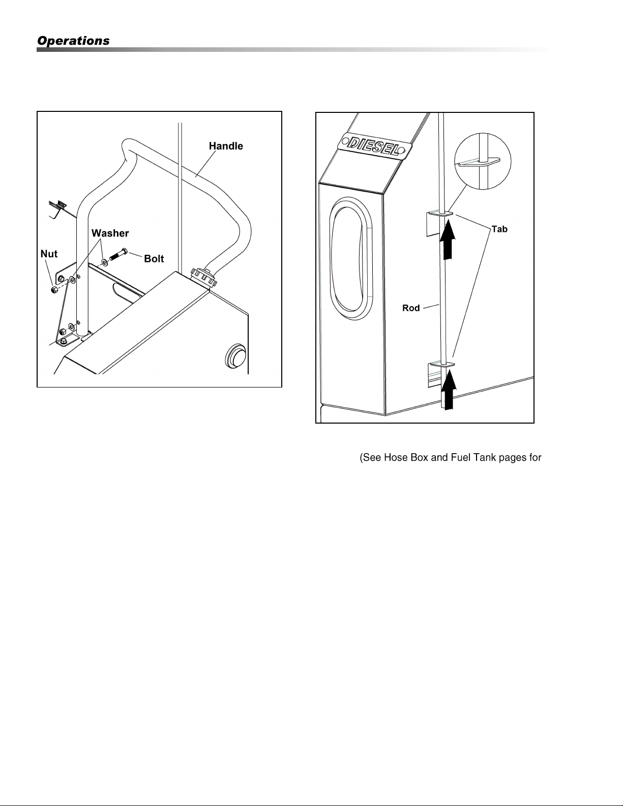
Accessory Assembly Instructions
Handle Installation
Align the 4 holes in the handle with the holes in the
back plate, install the fasteners and washers supplied.
(See Hose Box and Fuel Tank pages for fastener part
numbers.)
NOTE: Fastener assembly torque to install handle:10
ft-lbs (due to hollow tube handle.)
Safety Rod installation
Slide the rod through both holes in the tabs. To secure
rod, bend both tabs up slightly, until the rod does not
move freely.
fastener part numbers.)
Kärcher SMT Operator’s Manual 9.800-504.0 - G
17
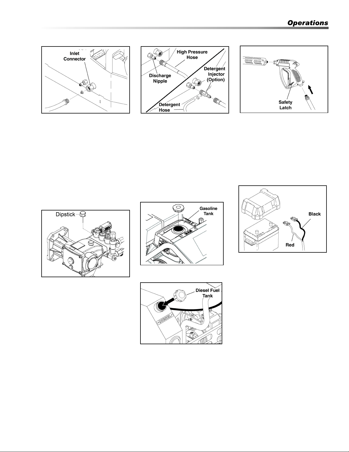
Assembly Instructions
STEP 1: Attach a 5/8" garden hose to
inlet connector. Minimum flow should
be 5 gpm.
STEP 4: Check oil level on sight
glass on backside of pump. Oil
should be visible one-half way up
sight glass (10-40W non-detergent).
The oil level can also be checked by
using the dipstick on the top of the
pump.
STEP 2: Attach high pressure hose
to discharge nipple using quick
coupler. Lock coupler securely into
place by pulling back coupler collar
and inserting it onto discharge nipple,
then pushing collar forward to lock in
place.
NOTE: If using detergent injector,
attach detergent injector to
discharge nipple using quick
coupler. Attach high pressure hose
to other end of detergent injector.
STEP 5: Fill gasoline tank and check
engine oil.
Fill diesel tank with diesel fuel.
CAUTION: Do not confuse diesel
fuel and gasoline when filling
tanks. Keep proper fuel in proper
tanks.
ATTENTION: Ne pas confondre du
carburant diesel et l'essence au
moment de remplir les réservoirs.
NOTE: Diesel Fuel Shut-off must
be in the ON position prior to
turning on burner.
STEP 3: Attach wand to spray gun
using teflon tape on threads to
prevent leakage. Attach swivel
connector on discharge hose to
spray gun using teflon tape on
threads. Attach swivel connector on
high pressure hose to spray gun
using teflon tape on threads. Engage
safety latch to prevent from triggering
gun.
STEP 6: On electric start models,
you will need to install a battery
making sure that the red cable is
attached to the positive terminal. Use
a Group U1 garden tractor style type
of battery rated for 300 CCA (battery
not included).
NOTE: Battery is required for
burner to operate.
CAUTION: These machines are
intended to be protected from
outside environments.
ATTENTION: Ces machines sont
conçues pour être protégées
contre l'environnement extérieur.
CAUTION: Risk of injury. Discon-
nect battery ground terminal
before servicing.
ATTENTION: Risque de blessures.
Débrancher la borne de mise à la
terre de la batterie avant de
procéder à des opérations d'entre-
tien.
Kärcher SMT Operator’s Manual 9.800-504.0 - G

18
Installation
Place machine in a convenient location providing
ample support, draining and room for maintenance.
This machine is intended for outdoor use. Machine
must be stored indoors when not in use.
Location
The location should protect the machine from
damaging environmental conditions, such as wind,
rain, and freezing.
1. This machine should be run on a level surface
where it is not readily influenced by outside
sources such as strong winds, freezing tempera-
tures, rain, etc. It should be located to allow acces-
sibility for refilling of fuel, adjustments and
maintenance. Normal precautions should be taken
by the operator of the machine to prevent moisture
from reaching the electrical controls.
2. It is recommended that a partition be made
between the wash area and the machine to
prevent water spray from coming in contact with
the machine. Excess moisture reaching any
electric components or electrical controls will
reduce machine life and may cause electrical
shorts.
3. During installation of the machine, beware of
poorly ventilated locations or areas where exhaust
fans may cause an insufficient supply of oxygen.
Sufficient combustion can only be obtained when
there is a sufficient supply of oxygen available for
the amount of fuel being burned. If necessary to
install a machine in a poorly ventilated area
outside, fresh air may have to be piped to the
burner and a fan installed to bring air into the
machine.
Avoid small locations or areas near exhaust fans.
Placement
Do not locate near any combustible material. Keep all
flammable material at least 20 feet away.
Allow enough space for servicing the machine.
Local code will require certain distances from floor and
walls. (Two feet away from walls should be adequate.)
Water Source
The water source for the pressure washer should be
supplied by a minimum 5/8" I.D. garden hose with a city
water pressure of not less than 5 GPM. If the water
supply is inadequate, or if the garden hose is kinked,
the attached pressure washer will run very rough and
the burner will not fire.
Connection
Connect the wand, nozzle, hose and spray gun (where
applicable). On pipe thread connections, use Teflon
tape to avoid water leaks. (See Component Identifica-
tion).
Kärcher SMT Operator’s Manual 9.800-504.0 - G
19
Operating Instructions
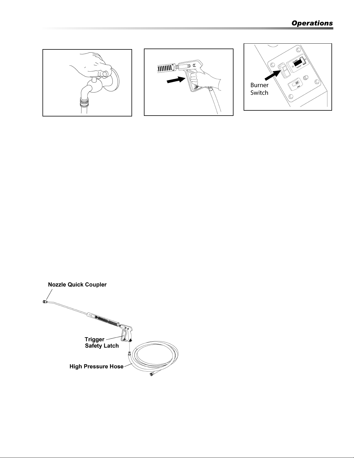
STEP 1: Turn water on.
STEP 2: Follow engine manual
provided to start engine.
WARNING: Starter cord kickback
(rapid retraction) can result in
bodily injury. Kickback will pull
hand and arm toward engine
faster than you can let go. Always
relieve spray gun pressure before
pulling starter cord. Pull starter
cord slowly until resistance is felt,
then pull rapidly
AVERTISSEMENT: Le retour du
cordon de lancement (rétraction
rapide) peut causer des lésions
corporelles. La rétraction rapide
de la corde du démarreur (recul)
attire la main et le bras vers le
moteur plus vite qu'il n'est
possible de lâcher la corde.
Toujours réduire la pression du
pistolet pulvérisateur avant de
tirer sur le cordon de lancement.
Tirer lentement sur le cordon de
lancement jusqu'à ce qu'une
résistance soit sentie, puis tirer
rapidement.
STEP 3: After engine has started,
turn Burner Switch ON. Grip spray
gun handle securely and pull
trigger. Burner should ignite.
Kärcher SMT Operator’s Manual 9.800-504.0 - G
NOTE: High pressure nozzle must be inserted at
end of wand to obtain high pressure. To apply
detergent, read operator's manual.
20
Detergents & General
Operating Techniques
WARNING: Some detergents may
be harmful if inhaled or ingested,
causing severe nausea, fainting or
poisoning. The harmful elements
may cause property damage or
severe injury.
AVERTISSEMENT: Certains
détergents peuvent être dangereux
s'ils sont inhalés ou ingérés,
provoquant de fortes nausées,
desévanouissements et
l'empoisonnement. Les éléments dangereux peuvent
causer des dommages à la propriété ou des blessures
graves.
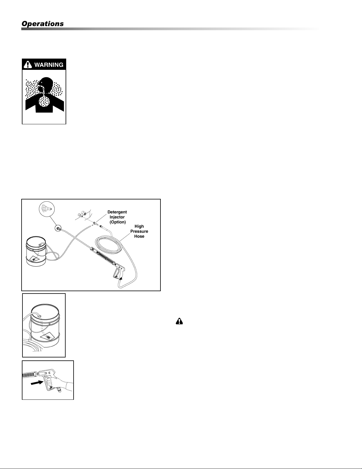
STEP 1: Connect high pressure hose to injector with quick
coupler (check to make sure locking coupler sleeves are in
proper position before applying water pressure. If using
detergent injector, connect it to discharge nipple on
machine.
STEP 2: Use detergent designed
specifically for pressure washers.
Household detergents could damage
the pump. Prepare detergent solution
as required by the manufacturer. Fill a
container with pressure washer deter-
gent. Place the filter end of detergent
suction tube into the detergent
container.
STEP 3: Apply safety latch to spray
gun trigger. Turn variable pressure
control handle until discharge water
exits both tubes. Secure black
detergent nozzle into quick coupler
if you have a single wand.
NOTE: Detergent cannot be applied using Red, Yellow,
Green or White nozzles.
STEP 4: With the engine running, pull trigger to operate
machine. Liquid detergent is drawn into the machine and
mixed with water. Apply detergent to work area. Do not
allow detergent to dry on surface.
Thermal Pump Protection
If you run the engine on your pressure washer for 3-5
minutes without pressing the trigger on the spray gun,
circulating water in the pump can reach high tempera-
tures. When the water reaches this temperature, the pump
protector engages and cools the pump by discharging the
warm water onto the ground. This thermal device prevents
internal damage to the pump.
Cleaning Tips
Pre-rinse cleaning surface with fresh water. Place
detergent suction tube directly into cleaning solution and
apply to surface at low pressure (for best results, limit your
work area to sections approximately 6 feet square and
always apply detergent from bottom to top). Allow
detergent to remain on surface 1-3 minutes. Do not allow
detergent to dry on surface. If surface appears to be
drying, simply wet down surface with fresh water. If
needed, use brush to remove stubborn dirt. Rinse at high
pressure from top to bottom in an even sweeping motion
keeping the spray nozzle approximately 1 foot from
cleaning surface. Use overlapping strokes as you clean
and rinse any surface. For best surface cleaning action
spray at a slight angle.
Recommendations:
• Before cleaning any surface, an inconspicuous
area should be cleaned to test spray pattern and
distance for maximum cleaning results.
• If painted surfaces are peeling or chipping, use
extreme caution as pressure washer may remove
the loose paint from the surface.
• Keep the spray nozzle a safe distance from the
surface you plan to clean. High pressure wash a
small area, then check the surface for damage. If
no damage is found, continue to pressure
washing.
CAUTION - Never use
• Bleach, chlorine and other corrosive chemicals
• Liquids containing solvents (i.e., paint thinner,
gasoline, oils)
• Tri-sodium phosphate products
• Ammonia products or Acid-based products
ATTENTION: Ne jamais utiliser :
• Eau de Javel, produits à base de chlore et autres
produits chimiques corrosifs
• Liquides contenant des solvants (c.-à-d. diluant à
peinture, essence, huiles, etc.)
• Produits à base de tripolyphosphate de sodium
• Ammoniac ou produits à base d'acide
These chemicals will harm the machine and will damage
the surface being cleaned.
Kärcher SMT Operator’s Manual 9.800-504.0 - G
21
Shutting Down And
Clean-Up
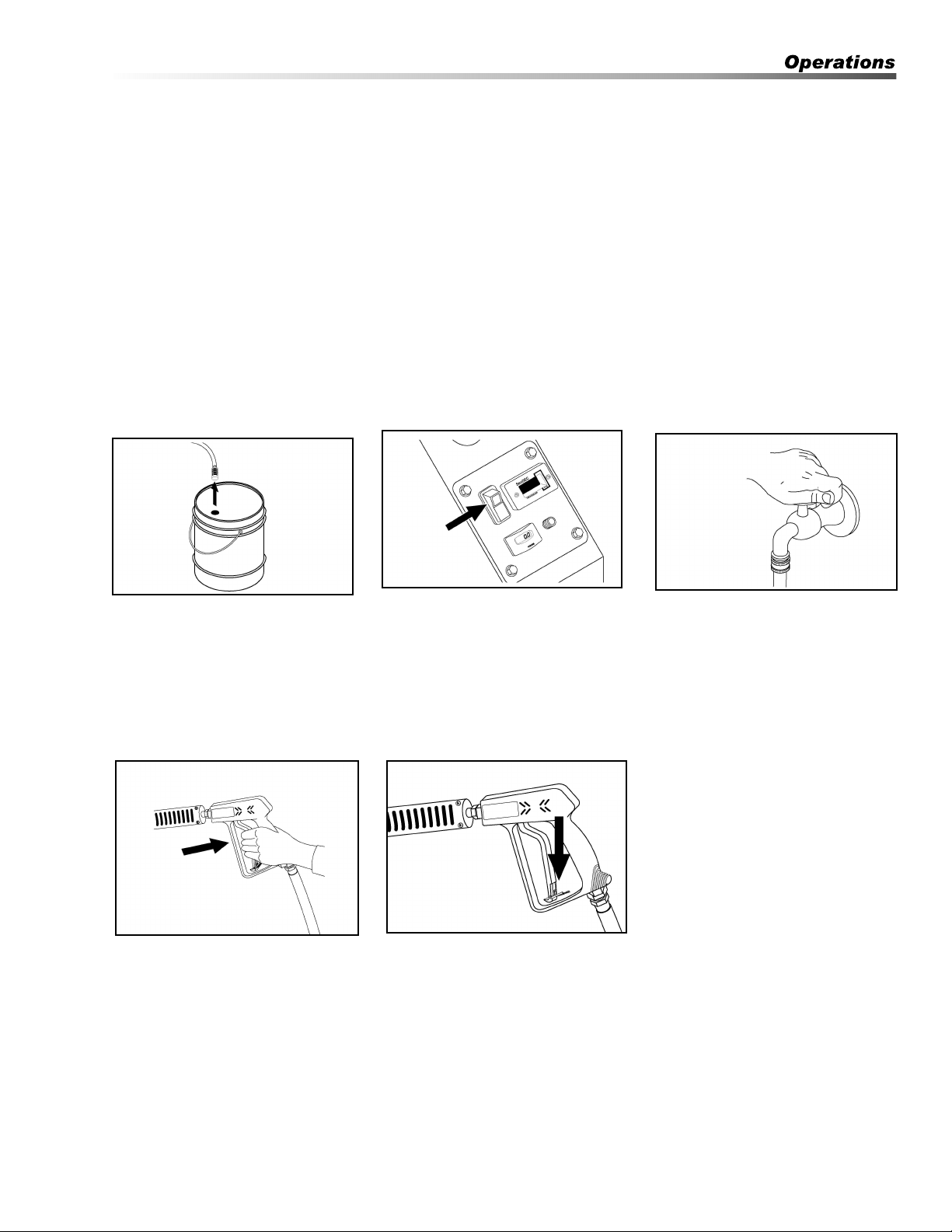
STEP 1: Remove detergent suction
tube from container and insert into
1 gallon of fresh water. Turn
variable pressure wand handle for
low pressure or connect the black
detergent nozzle. Pull trigger on
spray gun and siphon water for one
minute.
STEP 4: Turn garden hose water
off. Open the spray gun to relieve
remaining pressure.
STEP 2: Turn burner switch off and
continue spraying water, allowing
the water to cool. After water has
cooled to less than 100°F, turn off
engine. Protect from freezing.
STEP 5: Lock trigger gun safety
lever to prevent unintentional
pulling of trigger.
STEP 3: Turn off water supply.
Kärcher SMT Operator’s Manual 9.800-504.0 - G
Rinsing
It will take a few seconds for the detergent to clear.
Apply safety latch to spray gun. Remove black soap
nozzle from the quick coupler. Select and install the
desired high pressure nozzle. NOTE: You can also
stop detergent from flowing by simply removing
detergent siphon tube from bottle.
22
Storage
CAUTION: Always store your pressure washer in a
location where the temperature will not fall below
32°F (0°C). The pump in this machine is susceptible
to permanent damage if frozen. FREEZE DAMAGE
IS NOT COVERED BY WARRANTY.
ATTENTION: Toujours entreposer la laveuse à
pression dans un endroit où la température ne sera
pas inférieure à X °C (X °F). La pompe sur cette
machine est susceptible de subir des dommages si
elle est exposée au gel. LES DOMMAGES DUS AU
GEL NE SONT PAS COUVERTS PAR LA
GARANTIE.
1. Stop the pressure washer, squeeze spray gun
trigger to release pressure.
2. Detach water supply hose and high pressure hose.
3. Turn on the machine for a few seconds, until
remaining water exits. Turn motor off immediately.
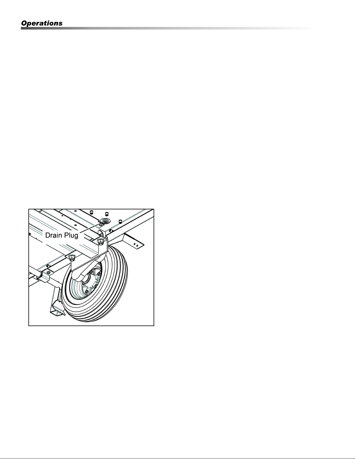
4. Drain the fuel from the fuel tank.
5. Do not allow high pressure hose to become kinked.
6. Store the machine and accessories in a room
which does not reach freezing temperatures.
CAUTION: Failure to follow the above directions
will result in damage to your pressure washer.
ATTENTION: Le non-respect des directives ci-
dessus entraînera des dommages à la laveuse à
pression.
When the pressure washer is not being operated or is
being stored for more than one month, follow these
instructions:
1. 1.Replenish pump oil to upper level.
2. 2.Drain fuel from fuel tank, fuel line and filter.
3. 3.Cover the pressure washer and store in a clean,
dry place that is well ventilated away from open
flame or sparks.
After Extended Storage
CAUTION: Prior to restarting, thaw out any
possible ice from pressure washer hoses, spray
gun or wand.
ATTENTION: Avant de redémarrer, faire fondre la
glace se trouvant sur les boyaux, le pistolet
pulvérisateur ou la lance de la laveuse à pression.
Kärcher SMT Operator’s Manual 9.800-504.0 - G

23
Preventative Maintenance
1. Use clean fuel — kerosene, No. 1 home heating
fuel or diesel fuel. Clean or replace fuel filter every
100 hours of operation. Avoid water contaminated
fuel as it will seize up the fuel pump. De-soot coils
monthly. Use an additive if diesel is being used.
2. Check to see that the attached pressure washer
water pump is properly lubricated.
3. Follow winterizing instructions to prevent freeze
damage to pump and coils.
4. Always neutralize and flush detergent from system
after use.
5. If water is known to be high in mineral content, use
a water softener on your water system, or descale
as needed.
6. Do not allow acidic, caustic or abrasive fluids to be
pumped through the system.
7. Always use high grade quality cleaning products.
8. Never run attached pressure washer pump dry for
extended periods of time.
9. If machine is operated with smoky or eye burning
exhaust, coils will soot up, preventing water from
reaching maximum operating temperature. (See
section on Maintenance and Service).
10. Never allow water to be sprayed on or near the
motor or burner assembly or any electrical compo-
nent.
11. Descale coils as per instructions.
It is advisable, periodically, to visually inspect the
burner. Check air inlet to make sure it is not clogged or
blocked. Wipe off any oil spills and keep equipment
clean and dry.
The areas around the pressure washer should be kept
clean and free of combustible materials, gasoline and
other flammable vapors and liquids.
The flow of ventilating air to the burner must not be
blocked or obstructed in any manner.
Maintenance And Service
Unloader Valves
Unloader valves trap pressure in the line when a shut-
off spray gun is closed. Machines with unloader valves
are preset and tested at the factory before shipping.
Tampering with the factory settings may cause
personal injury and/or property damage and will void
the manufacturer's warranty.
Winterizing Procedure
Damage due to freezing is not covered by warranty.
Adhere to the following cold weather procedures
whenever the washer must be stored or operated
outdoors under freezing conditions.
During winter months, when temperatures drop below
32°F, protecting your machine against freezing is
necessary. Store the machine in a heated room. If this
is not possible then mix a 50/50 solution of anti-freeze/
water or windshield washer fluid with water in a 5 gallon
bucket. Place a short section of garden hose into the
bucket and connect it to the machine. Elevate the
bucket and turn the pump on to siphon the anti-freeze
through the machine. If compressed air is available, an
air fitting can be screwed into the inlet connector and by
injecting compressed air, all water will be blown out of
the system.
High Limit Hot Water Thermostat
For safety, each machine is equipped with a high limit
control switch. In the event the temperature of the water
should exceed its operating temperature, the high limit
control will turn the burner off until the water cools.
Pumps
Use only 10-40W weight non-foaming oil. Change oil
after first 50 hours of use. Thereafter, change oil every
year or at 500 hour intervals. Oil level should be
checked by using the dipstick found on the top of the
pump or by the red dot visible through the oil gauge
window. Oil should be maintained at that level.
Cleaning of Coils
In alkaline water areas, lime deposits can accumulate
rapidly inside the coil pipes. This growth is increased by
the extreme heat build up in the coil. The best preven-
tion for liming conditions is to use high quality cleaning
detergents. In areas where alkaline water is an extreme
problem, periodic use of descale powder will remove
lime and other deposits before coil becomes plugged.
Kärcher SMT Operator’s Manual 9.800-504.0 - G

24
Descaling Coils With A Pressure Washer
Periodic flushing of coils is recommended.
1. Fill a 5 gallon bucket with 4 gallons of water, then
add 1 lb. of descaling powder.
Mix thoroughly.
2. Remove the high pressure nozzle from the
pressure wand and put the wand into the bucket.
Secure the trigger on the spray gun into the open
position.
3. Attach a short section (3-5 ft.) of garden hose to
the attached pressure washer to siphon solution
from the elevated bucket. Start up pressure
washer, allowing solution to be pumped through
pressure washer and into HPB coils and back into
the bucket. Solution should be allowed to circulate
2-4 hours.
4. After circulating solution flush entire system with
fresh water.
Fuel
Use clean fuel oil that is not contaminated with water
and debris. Replace fuel filter and drain tank every 100
hours of operation.
Use No. 1 or No. 2 Heating Oil (ASTM D306) only.
NEVER use gasoline in your burner tank. Gasoline is
more combustible than fuel oil and a serious explosion
could result. NEVER use crankcase or waste oil in your
burner. Fuel unit malfunction could result from contami-
nation.
Fuel Control System
These machines utilize a fuel solenoid valve located on
the fuel pump to control the flow of fuel to the combus-
tion chamber. This solenoid valve, which is normally
closed, is activated by a flow switch when water is
flowing through it. When an operator releases the
trigger on the spray gun, the flow of water through the
flow switch stops, turning off the current to the fuel
solenoid. The solenoid then closes, shutting off the
supply of fuel to the combustion chamber. Controlling
the flow of fuel in this way allows for an instantaneous
burn or no burn situation, thereby eliminating high and
low water temperatures, and combustion smoke
normally associated with machines incorporating a
spray gun.
Rupture Disk
If pressure from pump or thermal expansion should
exceed safe limits, the rupture disk will burst allowing
high pressure to be discharged through hose to ground.
When disk ruptures it will need to be replaced.he
Rupture Disk should be replaced every two years.
CAUTION: Periodic inspection is recommended to
insure that the fuel solenoid valve functions
properly. This can be done by operating the
machine and checking to see that when the trigger
on the spray gun is in the off position, the burner is
not firing.
ATTENTION: Une inspection périodique est
recommandée pour assurer que l'électrovalve
d'alimentation en carburant fonctionne
correctement. Cela peut être effectué en utilisant la
machine et en s'assurant que le brûleur n'est pas
allumé lorsque le pistolet pulvérisateur se trouve
en position d'arrêt.
Burner Nozzle
Keep the tip free of surface deposits by wiping it with a
clean, solvent-saturated cloth, being careful not to plug
or enlarge the nozzle. For maximum efficiency, replace
the nozzle each season.
Initial Air Adjustments
Allow sufficient air to obtain a clean burning flame by
loosening the lock screws and moving the air shutter
and if necessary the bulk air band.
Reduce the air supply until the flame tips appear
slightly smoky then increase the air just enough to
cause the flame tips to appear absolutely clean.
Oil Burner
Air Adjustment: The oil burner on this machine is
preset for operation at altitudes below 500 feet. If
operated at higher altitudes, it may be necessary to
adjust the air band for a #1 or #2 smoke spot on the
Bacharach scale.
To adjust, start machine and turn burner ON. Loosen
two locking screws found on the air band and close air
band until black smoke appears from burner exhaust
vent. Note air band position. Next, slowly open the air
band until white smoke just starts to appear. Turn air
band halfway back to the previously noted position.
Tighten locking screws.
For higher altitudes, the air band opening may need to
be increased; for lower altitude, the .air band may need
to be decreased.
For higher humidity, the air band opening may need to
be increased; for lower relative humidity, the .air band
may need to be decreased.
Kärcher SMT Operator’s Manual 9.800-504.0 - G
25
For higher ambient temperatures the air band opening
may need to be increased; for lower ambient tempera-
tures, the air band opening may need to be decreased.
Adjust to your operating location's environment as-
needed for best smoke spot and performance
compliant with local, state, and federal regulations
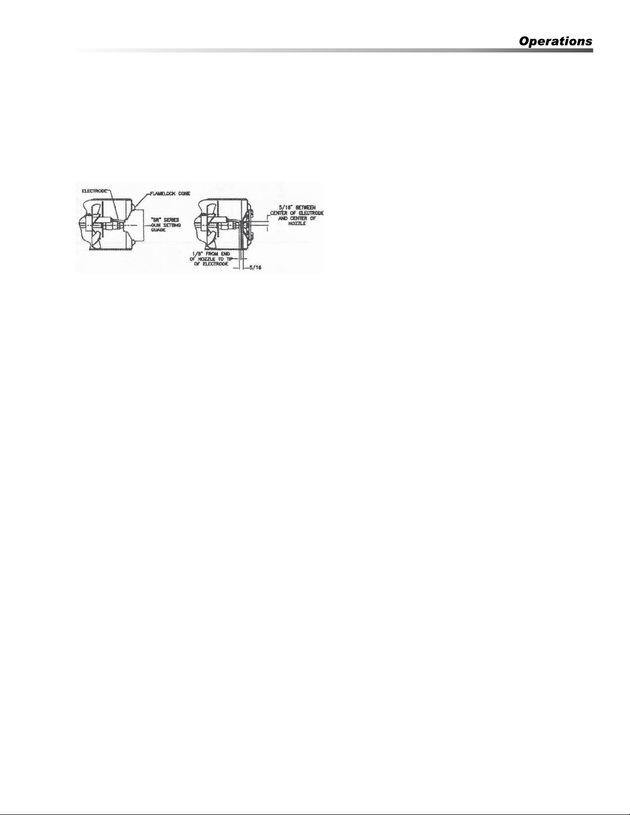
Electrode Setting
SR Series Gage
KNA Part Number 8.717-379.0
CAUTION: If white smoke appears from burner
exhaust vent during start-up or operation,
discontinue use and readjust air bands.
ATTENTION: Si de la fumée blanche s'échappe de
l'évacuation du brûleur pendant le démarrage ou le
fonctionnement, cesser d'utiliser et réajuster les
bandes d'air.
NOTE: If a flue is installed, have a professional
serviceman adjust your burner for a #1 or #2 smoke
spot on the Bacharach scale.
Fuel Pressure Adjustment
To adjust fuel pressure, First install a pressure gage
into the port just after the pump fuel exit. Turn the
adjusting screw (located at the regulator port)
clockwise to increase, and counterclockwise to
decrease. Do not exceed 200 psi or lower the pressure
below 130 PSI, when checked at the post-pump
pressure port.
The fuel pressure may need to be adjusted due to
altitude. For every 500 ft altitude above sea level, the
boiling point of water goes down 1 °F. At high altitude
environments, this boiling point change may require the
heat input to be lowered so the water input does not
turn to steam earlier than at the factory settings and
activate the pressure sensors and pressure relief
equipment when the unit is operated and much higher
altitudes from factory settings or local dealer site
settings. Check with your dealer before making local
site fuel pressure adjustments.
Also, as ambient temperature changes seasonally, the
fuel temperature in the feed tank and air temperature
inlet can impact fuel flow. In more extreme tempera-
tures, this local-site adjustment may also require
different fuel nozzles for fuel inlet temperatures that are
at seasonal extremes (higher or lower) in locations
where the temperature changes are beyond moderate
temperatures of between 40°F and 90°F. Colder
temperatures will make for a thicker flow and less fine a
fuel spray while hotter temperatures will make for a
thinner flow a more fine spray with the same nozzle.
Consider alternate nozzle configurations from the
baseline factory-supplied nozzle for operating in such
temperature extremes if performance is not meeting
needs with air band and fuel pressure settings alone.
NOTE: When changing fuel pump, a by-pass plug
must be installed in return line port or fuel pump will
not prime.
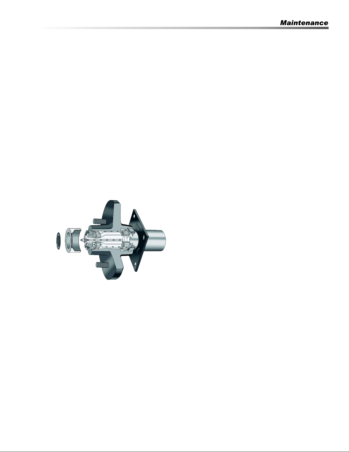
Removal of Soot and Heating Coil
In the heating process, fuel residue in the form of soot
deposits may develop on the heating coil and block air
flow which will affect burner combustion. When soot
has been detected on visual observation, the soot on
the coil must be washed off after following the coil
removal steps.
1. Remove the top wrap by unscrewing the four
screws from the sides and lift the top wrap off.
2. Remove Insulation.
3. Remove the two pipe nipples and associated
fittings.
4. Lift the coil out of the outer wrap.
CAUTION: The coil weighs about 80 lbs. Use proper
lifting techniques.
ATTENTION: La bobine pèse environ 80lb. Utiliser
des techniques de levage appropriées.
5. Clean, repair and replace the coil by reversing the
above steps.
Coil Reinstallation
Reinstall by reversing the above steps 5 through 1.
NOTE: The 12 VDC burner systems can draw as
much as 18 amps. For such motors to run properly,
the battery and engine charging system must be kept
in good condition, and the engine must run fast
enough to adequately charge the battery. Do not
throttle down the engine for any length of time
(For EHASR Only)
Kärcher SMT Operator’s Manual 9.800-504.0 - G

26
Hub Inspection Removal-
Replacement And Adjustments
A. Removal of Hub
1. Remove wheel
2. Remove grease cap
3. Remove cotter pin or bend tang washer on Posi-
Lube
4. Unscrew the spindle nut counter clockwise
5. Remove spindle washer
6. Remove hub from spindle
B. Seal Inspection and Replacement
1. Seals should be replaced each time the hub is
removed.
2. Pry the seal out of the hub with a screwdriver.
3. Tap new seal into place.
C. Bearing Maintenance, Adjustments, and
Replacement
1. Inspect for corrosion and wear.
2. If any rust or wear exists on the bearing then
remove and replace.
3. If bearings are found to be in good condition, then
cleaning and repacking the grease is all that is
needed.
NOTE: Do not spin bearings with compressed air.
4. Hand pack each bearing individually using a
premium lithium base wheel bearing grease.
5. Reinstall the hub, reversing the procedure above
using the bearing adjustment procedures below.
6. If you have the Posi–Lube system refer to the
“Posi-Lube Lubrication Procedure”.
D. Bearing Adjustment
Feel and Drag Method
Tighten slotted nut until hub drags slightly whe rotated.
(Rotating the hub while tightening the nut seats the
bearing.) Loosen the slotted nut 1/6 turn (1 hex) to align
nut slot with the cotter pin hole. Wheel should turn
freely. Insert new cotter pin through nut and spindle. If
necessary loosen, never tighten, nut to align slot with
the hole in the spindle. Bend one leg of cotter pin over
the end of the spindle and the other leg over the nut.
Tap legs slightly to set. Cotter pin must be tight. If
equipped with Posi-Lube, bend tang back into position.
Kärcher SMT Operator’s Manual 9.800-504.0 - G
27
Torque Wrench Method
Make sure nut is loose. Tighten nut with torque wrench
to an initial torque of 50 ft. lbs. Loosen nut from initial
torque and fingertighten. Insert new cotter pin through
nut and spindle. If equipped with Posi-Lube, reset tang.
If necessary loosen, never tighten, nut to align slot with
the hole in the spindle. Bend one leg of cotter pin over
the end of the spindle and the other leg over the nut.
Tap legs slightly to set. Cotter pin must be tight.
Posi-lube Lubrication Procedure
1. Remove the rubber cap at end of the grease cap.
2. Using a standard grease gun place the tip onto the
grease fitting at the end of the spindle.
3. Pump the grease into the fitting as you continue
pressure you will notice the old grease coming out
at the cap. When you begin to see the new grease,
remove the gun and clean off any excess and
replace the rubber cap.
Kärcher SMT Operator’s Manual 9.800-504.0 - G

28
Troubleshooting
PROBLEM POSSIBLE CAUSE
SOLUTION
LOW OPERATING
PRESSURE
Faulty pressure gauge Install new gauge.
Insufficient water supply
Use larger garden hose; clean filter washer at water
inlet.
Old, worn or incorrect spray nozzle
Match nozzle number to machine and/or replace
with new nozzle.
Plumbing or hose leak
Check plumbing system for leaks.
Re-tape leaks with teflon tape.
Faulty or mis-adjusted unloader
valve (where applicable)
Adjust unloader for proper pressure.
Install repair kit when needed.
Worn packing in pump Install new packing kit.
Fouled or dirty inlet or discharge
valves in pump
Clean inlet or discharge valves.
Worn inlet or discharge valves Replace with valve kit.
DETERGENT
NOT
DRAWING
Air leak
Tighten all clamps.
Check detergent lines for holes.
Valve in the injector head may be
blocked, dirty or damaged
Clean or replace valve in injector.
Filler screen on detergent suction
hose plugged
Clean or replace.
Dried up detergent plugging
metering valve
Disassemble and clean thoroughly.
High viscosity of detergent Dilute detergent to specifications.
Hole in detergent line(s) Repair hole.
Low detergent level Add detergent if needed.
Discharge water temperature above
180°F
Lower discharge water temperature.
PUMP RUNNING
NORMALLY BUT
PRESSURE LOW
ON INSTALLATION
Pump sucking air
Check water supply and possibility of
air seepage.
Valves sticking Check and clean or replace if necessary.
Unloader valve seat faulty Check and replace if necessary.
Nozzle incorrectly sized
Check and replace if necessary
(See serial plate for proper size).
Worn piston packing Check and replace in necessary.
FLUCTUATING
PRESSURE
Valves worn Check and replace if necessary.
Blockage in valve Check and replace if necessary.
Pump sucking air
Check water supply and air seepage at joints in
suction line.
Worn piston packing Check and replace if necessary.
PUMP
NOISY
Air in suction line
Check water supply and connections on
suction line.
Broken or weak inlet or discharge
valve springs
Check and replace if necessary.
Excessive matter in valves Check and clean if necessary.
Worn bearings Check and replace if necessary.
Kärcher SMT Operator’s Manual 9.800-504.0 - G

29
PROBLEM POSSIBLE CAUSE
SOLUTION
LOW WATER
TEMPERATURE
Improper fuel or water in fuel Drain fuel tank and replace with proper fuel.
Low fuel pressure Increase fuel pressure.
Weak fuel pump
Check fuel pump temperature. Replace
pump if needed.
Fuel filter partially clogged Replace as needed.
Soot build up on coils Clean coils with soot remover.
Lime build up on coils Clean inside of coils using coil cleaner.
Improper burner nozzle See Burner Specifications.
WATER
TEMPERATURE
TOO HOT
Incoming water to machine
warm or hot
Lower incoming water temperature.
Fuel pump pressure too high Lower fuel pressure.
Fuel pump defective Replace fuel pump.
Detergent line sucking air Tighten all clamps. Check detergent line for holes.
Defective high limit switch
(thermostat)
Replace.
Incorrect fuel nozzle size See Burner Specifications.
Insufficient water supplied Check GPM to machine.
Restricted water flow Check nozzle for obstruction, proper size.
MACHINE
SMOKES
WHILE
BURNER UNIT
IS RUNNING
OR
UNIT SMOKES AT
COLD-START
ONLY WHEN
BURNER
IS OFF
Improper air adjustment Readjust air bands on burner assembly
Fuel pressure is low <140 psi for
burner
Adjust fuel pump pressure to specifications
Burner nozzle is plugged or dirty
Replace nozzle. Check parts breakdown
for nozzle size
Burner nozzle spray pattern is
faulty
Replace nozzle. Check parts breakdown
for nozzle size
Heavy accumulation of soot on
coils and burner assembly
Remove coils and burner assembly,
clean thoroughly Call local dealer
Misaligned electrode setting Realign electrodes to specifications
Obstruction in smoke stack
Check for insulation blockage or other
foreign objects
Low engine RPM Increase RPM to correct specs. See serial plate
Fuel Pressure is too high for clean
burn (fuel PSI above 140 and below
200) and smokes when burner is off
Reduce fuel pressure PSI/Increase air band set for
cleaner without max water heat loss
Kärcher SMT Operator’s Manual 9.800-504.0 - G
NOTE: For additional service information for the engine, refer to the engine Operation and Maintenance Manual
included with pressure washers.

30
Pressure Washer Preventive Maintenance
This pressure washer was produced with the best available materials and quality craftsmanship. However, you as
the owner have certain responsibilities for the correct care of the equipment. Attention to regular preventative main-
tenance procedures will assist in preserving the performance of your equipment. Contact your Pressure Washers
dealer for maintenance. Regular preventative maintenance will add many hours to the life of your pressure washer.
Perform maintenance more often under severe conditions.
For additional service information for the engine, refer to the engine Operation and Maintenance Manual
included with pressure washers.
Maintenance Schedule
Engine Oil
(SAE 10W-30)
Inspect Daily
Change After first 25 hours
Filter Every 50 hours
Air Cleaner Inspect Every 50 hours or monthly
Clean Every 3 months
Battery level Check monthly
Engine Fuel Filter 500 hours or 6 months
Spark Plug Maintenance 500 hours or 6 months
Clean Fuel Tank(s) Annually
Replace Fuel Lines Annually
Pump Oil
(10W-40 non-foaming)
Inspect Oil level daily
Change After first 50 hours, then every 500 hours or annually
Clean Burner Filter Monthly (More often if fuel quality is poor)
Remove Burner Soot Annually
Burner Adjustment/Cleaning Annually
Replace Burner Nozzle Annually
Descale Coil Annually (More often if required)
Replace High Pressure Nozzle Every 6 months
Replace Quick Connects Annually
Clean Water Screen/Filter Weekly
Replace HP Hose Annually
Rupture Disk Replace every 2 years
Kärcher SMT Operator’s Manual 9.800-504.0 - G

31
Trailer Maintenance
Pump And Engine Oil Change Record
Trailer Maintenance Schedule
Item Function Required 3 Months or 3,000 Miles
6 Months or
6,000 Miles
12 Months
or 12,000
Miles
Hub/Drum
Check for abnormal wear and
scoring
X
Wheel Bearings &
Cups
Inspect for corrosion or wear;
clean and repack
X
Seals
Inspect for leakage; replace if
removed
X
Springs Inspect for wear, loss of arch
X
Suspension Parts
Inspect for bending, loose
fasteners, wear
X
Hangers Inspect welds for cracks
Wheel Nuts &
bolts
Tighten to specified torque
values
Re-torque after first 50 miles
of use and periodically re-
check the torque
X
Wheels
Inspect for cracks, dents, or
distortion
Tire Inflation
Pressure
Inflate tires to mfg's specifica-
tions
Before Every Use
Tire Conditions
Inspect for cuts, wear,
bulging, etc.
Date Oil Changed
Month/Day/Year
Estimated Operating
Hours Since Last Oil
Change
Date Oil Changed
Month/Day/Year
Estimated Operating
Hours Since Last Oil
Change
Kärcher SMT Operator’s Manual 9.800-504.0 - G

9.800-504.0 - Printed in U.S.A. or Mexico