246967-2
In s t a l l a t i o n and O p e r a t i o n Ma n u a l
G32D
• M o i s t u r e M o d e
• M u l t i - S t a g e C o o k i n g
• O p t i o n a l C o r e T e m p P r o b e

The reproduction or copying of any part of this manual by any means whatsoever is strictly forbidden unless authorized previously in writing
by the manufacturer.
In line with policy to continually develop and improve its products, Moffat Ltd. reserves the right to change the specifications and design
without prior notice.
© Copyright Moffat Ltd. January 2020.
Moffat Limited
Rolleston 7675
New Zealand
AUSTRALIA
Moffat Pty Limited
Web: www.moffat.com.au
E.Mail: [email protected]m.au
Main Office: (tel) +61 (03) 9518 3888
(fax) +61 (03 9518 3838
Service: (tel): 1800 622 216
Spares: (tel): 1800 337 963
Customer Service: (tel): 1800 335 315
(fax): 1800 350 281
CANADA
Serve Canada
Web: www.servecanada.com
E.Mail: [email protected]m
Sales: (tel): 800 551 8795 (Toll Free)
Service: (tel): 800 263 1455 (Toll Free)
NEW ZEALAND
Moffat Limited
Web: www.moffat.co.nz
E.Mail: [email protected].nz
Main Office: (tel): 0800 663328
UNITED KINGDOM
Blue Seal
Web: www.blue-seal.co.uk
E.Mail: sales@blue-seal.co.uk
Sales: (tel): +44 121 327 5575
(fax): +44 121 327 9711
Spares: (tel): +44 121 322 6640
(fax): +44 121 327 9201
Service: (tel): +44 121 322 6644
(fax): +44 121 327 6257
UNITED STATES
Moffat
Web: www.moffat.com
Sales: (tel): 800 551 8795 (Toll Free)
(tel): +1 336 661 1556
(fax): +1 336 661 9546
Service: (tel): 866 673 7937 (Toll Free)
REST OF WORLD
Moffat Limited
Web: www.moffat.co.nz
E.Mail: [email protected].nz
Contents List
Safety Information
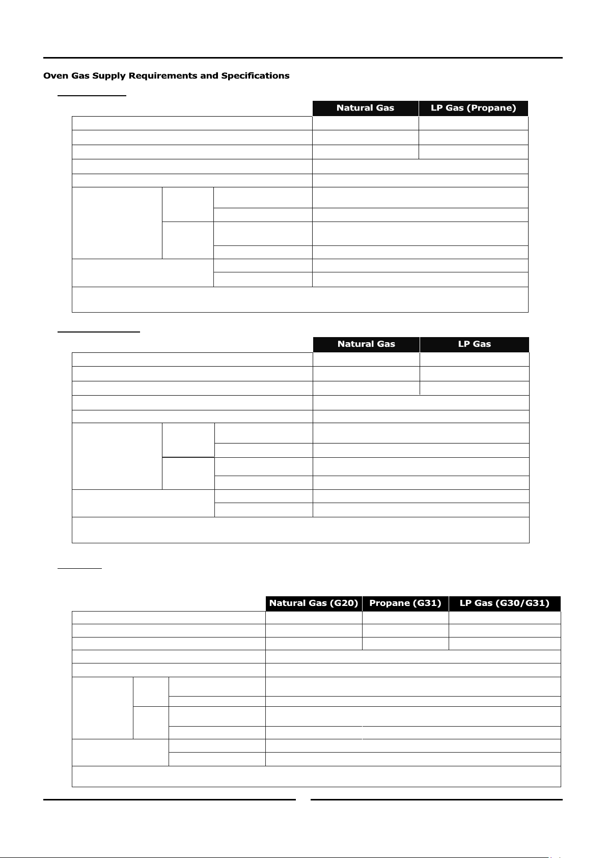
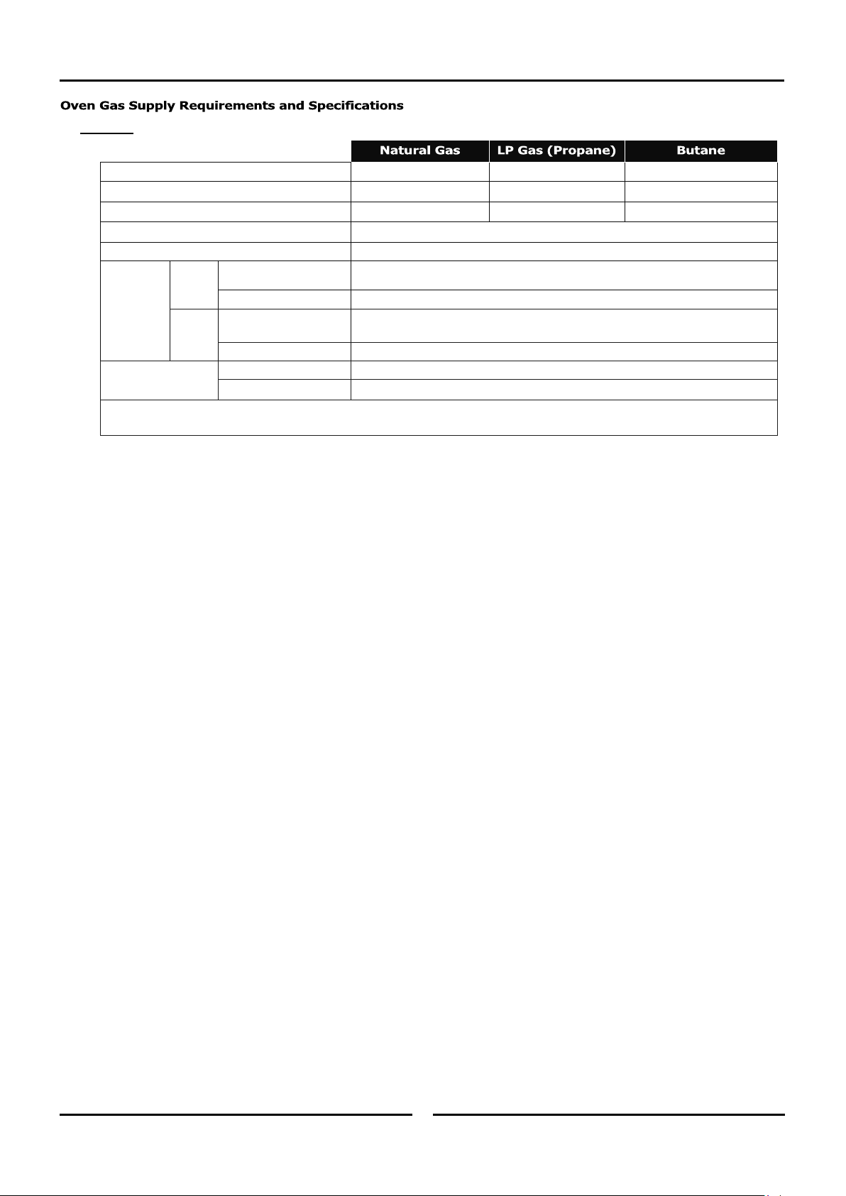
Oven Gas Supply Requirements and Specifications
Installation Requirements
Installation
Unpacking
Location
Clearances
Stand Mounted Ovens
Electrical Connection
Gas Connection
Water Connection
Recommended Water Specifications
Positioning and Levelling of Oven
Initial Start-Up
Commissioning
Operation Guide
Cooking in Manual Mode
Cooking in Manual Mode using Core Temp Probe
Cooking in Program Mode
Programs
Parameters
Programs Revision Numbering
Files
Changing Operator Settings
Operator Settings
Cleaning Guidelines
Oven Cleaning
Periodic Maintenance
Conversion Procedure
Table of Gas Specifications
Introduction
2
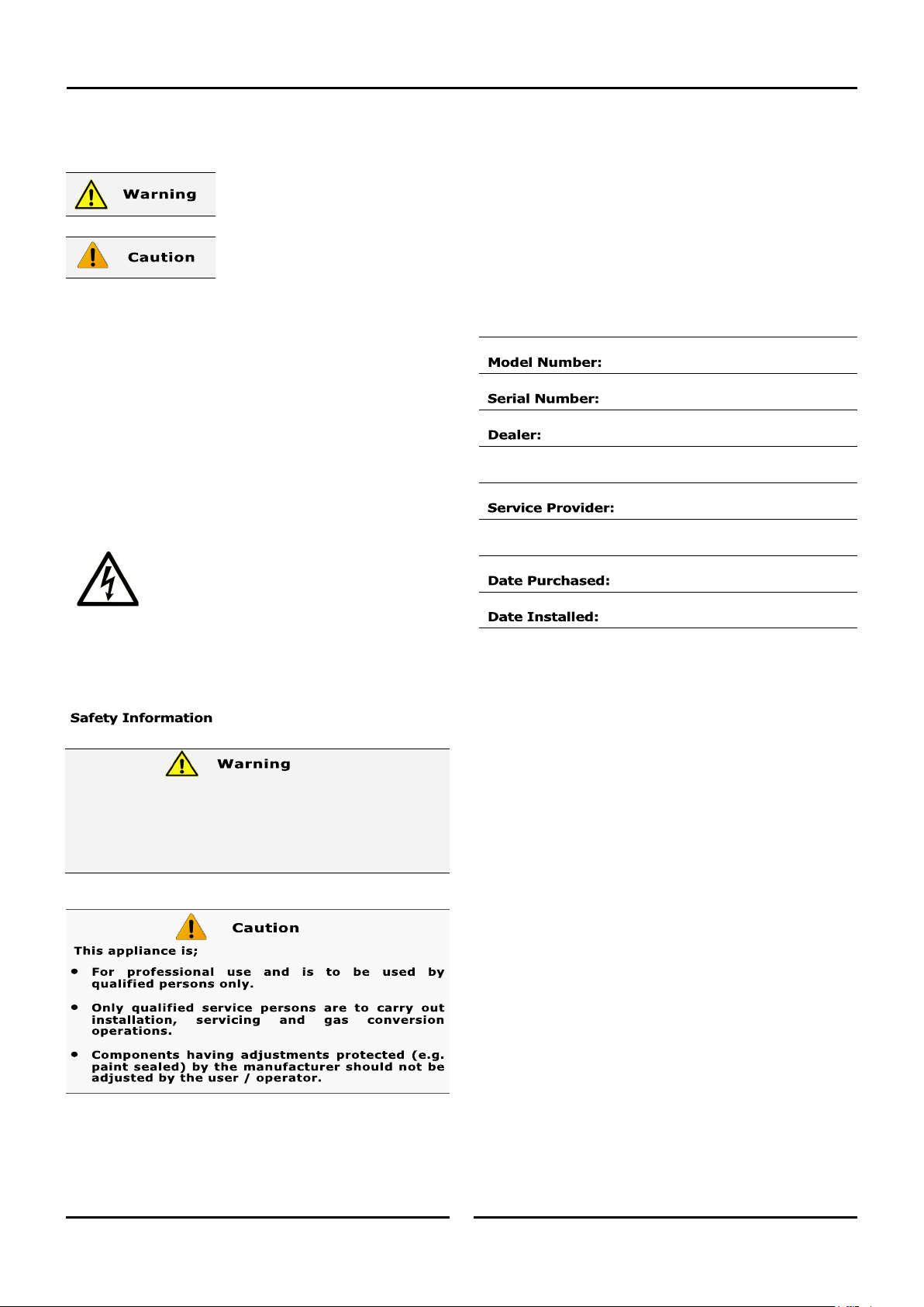
Before using your new oven, please read this instruction manual
carefully, pay particular attention to any information labelled
‘WARNING’, ‘CAUTION’, ‘IMPORTANT’ or ‘NOTE’ in this manual.
Indicates a hazardous situation
which, if not avoided, will result in
death or serious injury.
Indicates a hazardous situation
which, if not avoided, will result in
minor or moderate injury.
If you are unsure of any aspect of the installation, instructions or
performance of your oven, contact your TURBOFAN dealer promptly.
In many cases a phone call could answer your question.
Should you contact your TURBOFAN dealer on any matter concerning
this oven, please have the information provided opposite, readily
available.
This manual must be kept by the owner for future reference.
A record of the
Date of Purchase,
Date of Installation
and
Serial Number of the oven
should be recorded in the area
provided below.
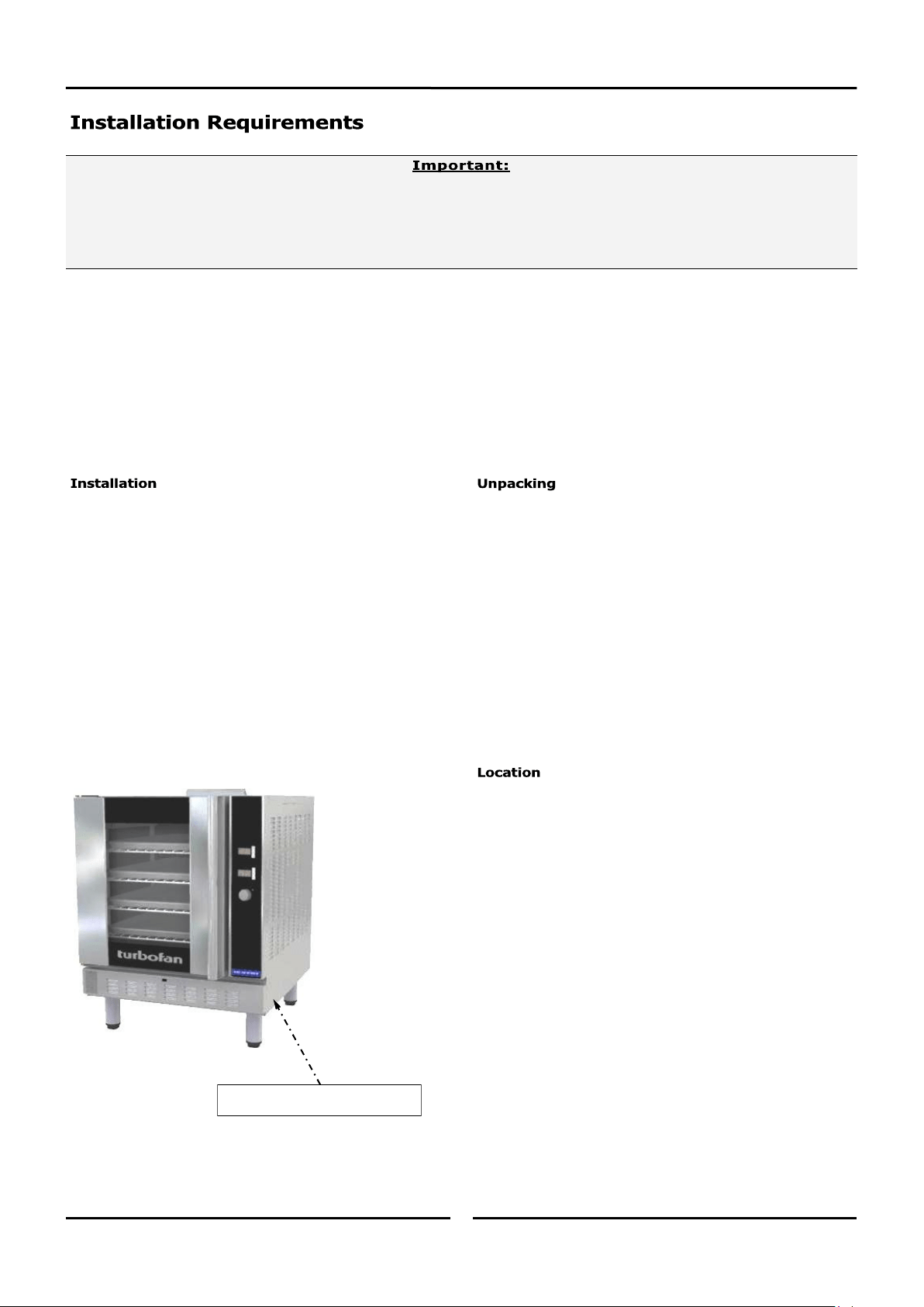
The serial number of this oven can be found on the
Technical Data Plate located on the front right hand side
panel, see diagram in ‘Installation Section’.
• DO NOT SPRAY AEROSOLS IN THE VICINITY OF THIS APPLIANCE
WHILE IT IS IN OPERATION.
• DO NOT STORE OR USE GASOLINE OR OTHER FLAMMABLE
VAPOURS, LIQUIDS OR MATERIAL IN THE VICINITY OF THIS OR
ANY OTHER APPLIANCE.
For your safety, please pay attention to the following symbols
marked on the appliance.
- Risk of electric shock.
No user serviceable parts inside.
Qualified service person access only.
Disconnect from power before servicing.
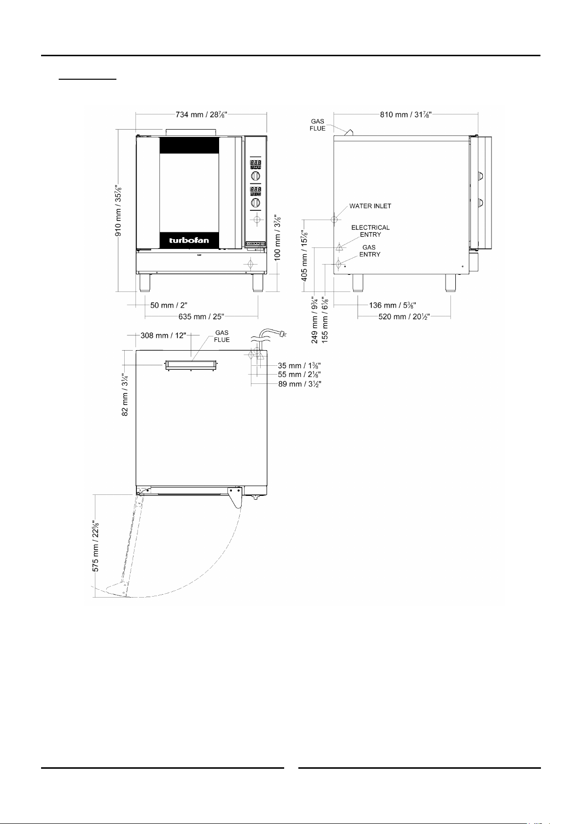
Specifications
3 3
G32D4/G32D5
Specifications
4 4
- Australia Only:
- New Zealand Only
- UK Only:
Category: II
2H3P /
II
2H3B/P.
Flue Type: A
1.
Input Rating 10 kW 10 kW 10 kW
Supply Pressure 20 mbar 30 - 37 mbar 28 - 30 mbar
Burner Operating Pressure 10 mbar 25 mbar 24.2 mbar
Gas Connection ½” BSP Male.
Electrical Power Ratings 220-240V, 1P+N+E, 50/60HZ, 200W.
Oven Tray
Details
G32D4
Tray Capacity
4, 18” x 26” / 460 x 660 Full Size Sheet Pan Capacity.
4, 600 x 400 Tray Capacity.
Tray Spacing 110mm.
Tray Capacity
4, 18” x 26” / 460 x 660 Full Size Sheet Pan Capacity.
4, 600 x 400 Tray Capacity.
G32D5
Tray Spacing 80mm.
Water Connection
Max Water Pressure 80 psi / 550 kPa.
Connection Size ¾” BSP.
NOTE: If the Moisture Mode cooking option is not required, the oven does not need to be connected to a water supply.
Input Rating 35 MJ/hr. 35 MJ/hr.
Supply Pressure 1.13 - 3.4 kPa. 2.75 - 5.0 kPa.
Burner Operating Pressure 0.75 kPa. 2.35 kPa.
Gas Connection ½” BSP Male.
Electrical Power Ratings
220-240V, 1P+N+E, 50/60HZ, 200W.
Oven Tray Details
G32D4
Tray Capacity
4, 18” x 26” / 460 x 660 Full Size Sheet Pan Capacity.
4, 600 x 400 Tray Capacity.
Tray Spacing 110mm.
Tray Capacity
4, 18” x 26” / 460 x 660 Full Size Sheet Pan Capacity.
4, 600 x 400 Tray Capacity.
G32D5
Tray Spacing 80mm.
Water Connection
Max Water Pressure
80 psi / 550 kPa.
Connection Size
¾” BSP.
NOTE: If the Moisture Mode cooking option is not required, the oven does not need to be connected to a water
supply.
Input Rating 35 MJ/hr. 35 MJ/hr.
Supply Pressure 1.13 - 3.4 kPa. 2.75 - 5.0 kPa.
Burner Operating Pressure 0.75 kPa. 2.42 kPa.
Gas Connection ½” BSP Male.
Electrical Power Ratings
220-240V, 1P+N+E, 50/60HZ, 200W.
Oven Tray Details
Tray Capacity
4, 18” x 26” / 460 x 660 Full Size Sheet Pan Capacity.
4, 600 x 400 Tray Capacity.
G32D4
Tray Spacing 110mm.
G32D5
Tray Capacity
4, 18” x 26” / 460 x 660 Full Size Sheet Pan Capacity.
4, 600 x 400 Tray Capacity.
Tray Spacing 80mm.
Water Connection
Max Water Pressure
80 psi / 550 kPa.
Connection Size
¾” BSP.
NOTE: If the Moisture Mode cooking option is not required, the oven does not need to be connected to a water
supply.
Specifications
5 5
- Export:
Input Rating 35 MJ/hr. 35 MJ/hr. 35 MJ/hr.
Supply Pressure 1.13 - 3.4 kPa. 2.75 - 5.0 kPa. 2.75 - 5.0 kPa.
Burner Operating Pressure 0.75 kPa. 2.35 kPa. 2.35 kPa.
Gas Connection ½” BSP Male.
Electrical Power Ratings
220-240V, 1P+N+E, 50/60HZ, 200W.
Oven Tray
Details
G32D4
Tray Capacity
4, 18” x 26” / 460 x 660 Full Size Sheet Pan Capacity.
4, 600 x 400 Tray Capacity.
Tray Spacing 110mm.
Tray Capacity
4, 18” x 26” / 460 x 660 Full Size Sheet Pan Capacity.
4, 600 x 400 Tray Capacity.
G32D5
Tray Spacing 80mm.
Water Connection
Max Water Pressure
80 psi / 550 kPa.
Connection Size
¾” BSP.
NOTE: If the Moisture Mode cooking option is not required, the oven does not need to be connected to a water supply.
Installation
6 6
This installation of this appliance must conform with local codes, or in the absence of local codes, must conform to the National Codes shown
below covering gas and electrical safety.
Australia / New Zealand: - AS/NZS5601 - Gas Installations.
- AS/NZS3000 - Wiring Rules.
United Kingdom: - Gas Safety (Installation & Use) Regulations 1998.
- BS6173 - Installation of Catering Appliances.
- BS5440 1 & 2 - Installation Flueing & Ventilation.
- BS7671 - Requirements for Electrical Installations.
Ireland: - IS 820 - Non - Domestic Gas Installations.
• Installation shall comply with local gas, electrical and health and safety requirements.
• It is most important that this oven is installed correctly and that oven operation is correct before use.
• If you have any questions regarding the proper installation and / or operation of this oven, please contact your local
Turbofan distributor.
Technical Data Plate - Location
Installations must be carried out by authorised persons only.
Failure to install equipment to the relevant codes and manufacturers
specifications shown above, will void the warranty.
This oven must be electrically earthed / grounded in accordance
with local codes.
Installation must allow for a sufficient flow of fresh air for the
combustion air supply. Combustion air requirements:
Natural Gas 10m³/hr.
LP Gas (Propane) 9m³/hr.
Components having adjustments protected (e.g. paint sealed) by
manufacturer are only to be adjusted by an authorised service
agent. They are not to be adjusted by the installation person.
1. Remove all packaging and transit protection including all
protective plastic coating from the exterior stainless steel
panels.
2. Check the oven and supplied parts for damage. Report any
damage immediately to the carrier and distributor.
3. Check that the following parts have been supplied with your
oven:-
4 x Leg Adjustable.
4. Report any deficiencies to the distributor who supplied your
oven.
5. Securely fit the 4 legs supplied with the oven.
6. Check that the available gas and electrical supply is correct to
that shown on the Technical Data Plate located on the front
right hand side panel.
• Also refer to ‘Specifications’ section, ‘Oven
Specifications Tables’ for specifications details.
1. This oven must be installed in an area of adequate air supply.
Adequate ventilation is essential, to prevent dangerous build up
of combustion products. DO NOT obstruct the air flow around
the ventilation slots.
2. This oven must be fitted on supplied legs in all installations.
(When installed on a manufacturers stand, the legs are used to
locate the oven in the correct position.
3. All air for burner combustion is supplied from beneath the
appliance. The legs must always be fitted and no obstructions
placed on the underside or around the base of the appliance, as
obstructions will cause incorrect operation and / or failure of the
appliance.
4. Installation must allow for a sufficient flow of fresh air for the
combustion air supply.
5. The area around the appliance must be kept free and clear
from combustibles.
6. Position oven in its approximate working position. It should be
positioned so that the control panel and oven shelves are easily
reachable for loading and unloading.
7. Use a spirit level to ensure oven is level from side to side and
front to back. (If this is not carried out, uneven cooking could
occur).

Installation
7 7
A ½" BSP connection is provided at the bottom rear of the oven.
It is important that adequately sized piping run directly to the
connection joint on the oven with as few tees and elbows as
possible to give maximum supply volume.
A suitable jointing compound which resists the break down action of
LPG must be used on every gas connection.
Check all gas connections for leakages using soapy water or other
gas detecting equipment.
Check the technical data plate located on the front right hand
corner of the oven, for correct operating pressure and gas orifice
size for the gas being used, before operation.
The appliance combination gas valve is fitted with an internal
regulator for adjusting the operating pressure. To access, remove
appropriately marked service panel from beneath the oven door.
Unscrew and remove regulator cap from the gas valve. Adjust the
regulator to achieve the stated pressure. Also refer to the
‘Specifications’ section.
NOTE: The Pressure Test Point is located behind the front
service panel beneath the oven door.
NOTE: If the Moisture Mode cooking option is not required,
the oven does not need to be connected to a water
supply.
1. Tighten the 2 screws securing the
water connection to the rear of the
oven. (These have purposely been
left loose to prevent damage to the
water connection during transit).
2. Connect a cold water supply to the
water inlet (R ¾” Connector) on the
oven.
- Max Inlet Pressure 80psi / 550kPa.
3. Turn ‘On’ the water supply and check for leaks.
In order to prevent corrosion or scaling in the oven and water
system due to supplying water that is either too soft or too hard,
the following recommendations should be used as a guideline.
Hardness: Between 60 and 90ppm.
PH: Greater than 7.5.
Chlorides: Less than 30 ppm.
1. To ensure correct ventilation for the motor and controller, the
following minimum installation clearances are to be adhered to:
CLEARANCE FROM SOURCE OF HEAT.
A minimum distance of 300mm (12”) from the appliance
sides is required.
NOTE: Fixed installations require at least 500mm (20”)
clearance at the right hand side of oven for service
access.
For ovens that are to be mounted to a stand, the oven legs are
used to level the oven on the stand. Refer to the instructions sup-
plied with separately ordered stands for mounting details.
RCD (Residual Current Device) / GFCI (Ground-Fault Circuit-
Interrupter) protection of the power supply to this appliance is rec-
ommended.
Each oven should be connected to an adequately protected power
supply with an appropriate power cord.
An isolation switch mounted adjacent to, but not behind the oven
and must be readily accessible to the operator. This switch must be
clearly marked and readily accessible in case of fire.
Check the electricity supply is correct to as shown on the Technical
Data Plate on the front right hand corner of the oven side panel.
Ensure that the oven is fitted with the appropriate power cord and
plug.
The vent located on the top of the oven must NOT be
obstructed.
Do not use a naked flame to check for gas leakages.
Oven Vent
Top 600mm 200mm
LH / RH Side 75mm 75mm
Rear 75mm 75mm
This oven must be earthed / grounded.
Regulator
Cap
Pressure Test
Point
Tighten Screws.

Installation
8 8
1. Correctly locate the oven into its final operating position and
using a spirit level, adjust the oven feet so that the oven is level
and at the correct height.
Before using the new oven;
1. For first time use of the oven, operate the oven for about 1
hour at 200°C to remove any fumes or odours which may be
present.
2. Please refer to the Operation Section of this manual for details
on how to correctly operate and shutdown the oven.
Before leaving the new installation;
1. Check the oven functions in accordance with the operating
instructions specified in the ‘Operation’ section of this manual.
2. Ensure that the operator has been instructed in the areas of
correct lighting, operation, and shutdown procedure for the
appliance.
NOTE: If it is not possible to get the appliance to operate
correctly, shut off the gas and power supply and
contact the supplier of this appliance.
Operation
9 9
• This oven is intended for use in a commercial kitchen and must only be put to the use for which it was intended, i.e. cooking food
product. To use this oven correctly please read the following sections carefully:-
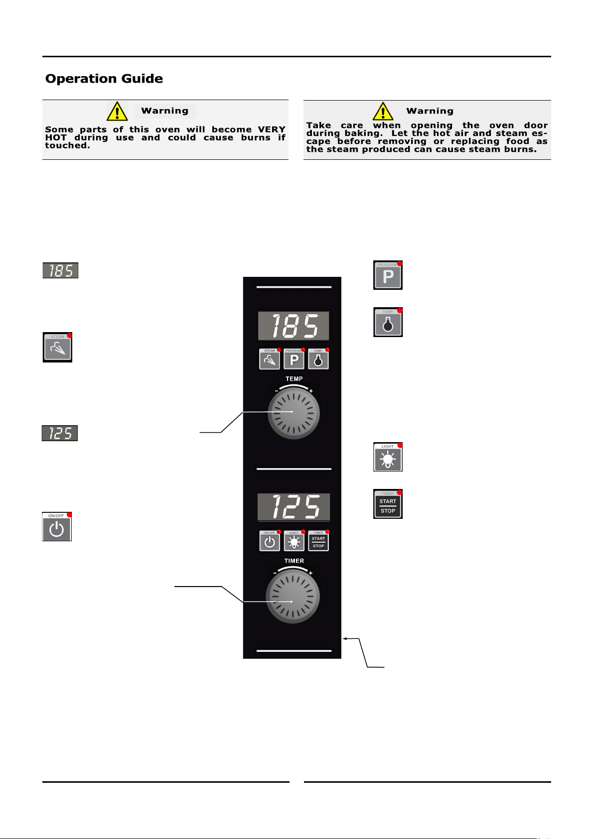
Temperature Display -
Shows pre-set chamber temperature.
When used with the ‘Temp’ key, dis-
play shows actual oven temperature for 5 sec-
onds.
Shows cooking programs and error codes.
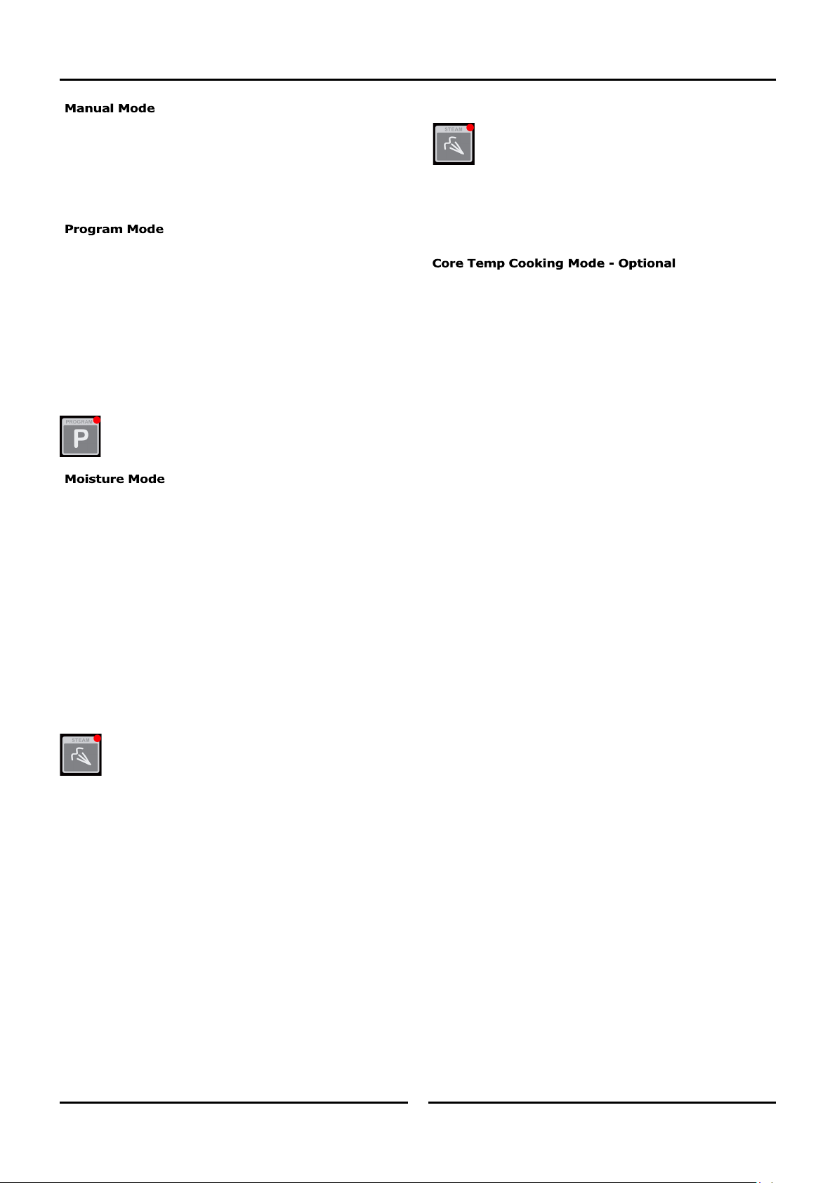
‘Steam’ Key and LED -
Used to set moisture level or to
provide a manual injection of moisture
when in Manual Moisture Mode.
LED is ‘On’ when automatic moisture injection is
set or when moisture is manually injected.
Temperature Adjustment Control
Time Display -
Shows cook time in full minutes only
from 180 - 10, and in minutes and seconds for
the final 10 minutes.
NOTE:
In Core Temp Mode, time display alternates
between ‘CP’ and set core probe temperature.
‘On/Off’ Key and LED -
Press ‘On/Off’ key once to turn the
oven ‘On’.
Press and hold ‘On/Off’ key for 1.5
seconds to turn the oven ‘Off’.
Time Adjustment Control
NOTE: In Core Temp Mode, ‘Timer’ knob is
used to set core probe temperature.
‘Program’ Key and LED -
Used to select cooking programs and to
set program operator settings.
‘Temp’ Key and LED -
Displays actual oven temperature for 5
seconds on Temperature Display. LED
‘On’ when heating element is on
(heating indicator).
LED flashes when Upper Display is showing
actual temperature.
NOTE:
In Core Temp Mode, this key is used to
display Actual Oven Temperature (Upper
Display) and Core Probe Temperature (Lower
Display).
‘Light’ Key and LED -
Switches oven lights ‘On/Off’. LED is
‘On’ when oven lights are ‘On’.
‘Timer-Start/Stop’ Key & LED -
The ‘Timer-Start/Stop’ key is used to
control the following functions:-
• Cancelling Alarm (All Modes).
• Starting Core Temp Mode (Core Temp
Mode).
• Starting Timer (Manual Mode).
• Re-setting Timer (Manual Mode).
• Starting Program (Program Mode).
• Cancelling and Re-setting Program
(Program Mode).
Core Probe Connection Point
Operation
10 10
Changing Moisture Mode Level
Press and hold the ‘Steam’ Key until the ‘H-X’ level is
displayed and flashing in the upper display.
Rotate the ‘Temp’ Knob -/+ to select Moisture Mode level
required.
Press the STEAM Key to confirm setting.
The ‘Moisture’ Mode level can be changed at anytime during
operation by following the setting method as described above.
An Optional Core Temp Probe Kit #236060 is available for
this oven.
This allows use of the Core Probe Cooking feature of this oven.
When the core probe is fitted to the connection point on control
panel side, the timer function and display becomes the core temp
probe temperature setting and display. Cooking completion is then
determined by the core temp probe reaching the set core probe
temperature.
To enable Core Probe Cooking Mode plug in the Core Probe.
The Timer Display will then change to '
CP'
(Core Probe).
The Timer Knob function will then be for Core Temp setting.
To disable Core Probe Cooking Mode, unplug the Core Probe.
The Timer Display and Knob will return to time function.
In Manual Mode the ovens settings are.
- Temperature Settings - 50-250C / 150-550F.
- Timer Settings - 0-180min or Infinite.
- Moisture Mode Settings - Off / On-Level.
- Oven Lights Settings - Off / On.
An Optional Core Probe can also be used in Manual Mode.
In Program Mode 20 Programs are able to be used.
In each program the following settings are possible.
- Temperature Settings - 50-250C / 150-550F.
- Timer Settings - 0-180min or Infinite.
- Moisture Mode Settings - Off / On-level.
- Oven Lights Settings - Off / On.
Three cooking stages can also be set in each of the 20 programs.
- All settings can be changed between cooking stages.
- At completion of each stage an end of stage alarm can also
be set.
Optional Core Probe can also be used in Program Mode.
Changing between Manual to Program Modes
Press ‘Program’ key to select Program Mode. The LED
will illuminate showing Program Mode now set.
Press ‘Program’ Key to return to Manual mode.
There are 6 levels of pre-set moisture injection.
Each level defines the number of moisture injection pulses per
moisture cycle during oven operation.
H-0 Manual Moisture Mode. Automatic Moisture Injection is ‘Off’.
Pressing ‘Steam’ key in this mode will inject 1 shot of steam
into the oven, ie, no steam injection without user input.
H-1 Level 1. - Minimum automatic moisture injection setting. One
moisture pulse per moisture cycle.
H-2 Level 2.
H-3 Level 3.
H-4 Level 4.
H-5 Level 5. - Maximum automatic moisture injection setting.
Five moisture pulses per moisture cycle.
Selecting Moisture Mode
Press ‘Steam’ key to activate Moisture Mode. ‘Steam’
key LED will illuminate when Moisture Mode is ‘On’.
Moisture Mode will operate at the preset level during the
cooking cycle.
• When Moisture Mode H-0 is selected, a shot of steam is
available whenever the oven is running, by pressing the
‘Steam’ key.
• When Moisture Mode H-1 to H-5 are selected, these
moisture modes will only operate when a program is
running, Core Temp Probe Mode has been selected or when
a timer is running in Manual Mode.
• When setting Moisture level, consider the Oven Set
Temperature. If set BELOW 100°C (212°F), water may pool
in oven as temperature will be too low to create steam.
Operation
11 11
On oven start-up the controller defaults to the following settings:-
Oven Temperature is set to 150°C (325°F).
Refer ‘Controller - Operator Settings’ section to change this start-up temperature.
Oven Timer is not set, display shows ‘ - - -’.
Moisture Setting is setting to Manual Injection.
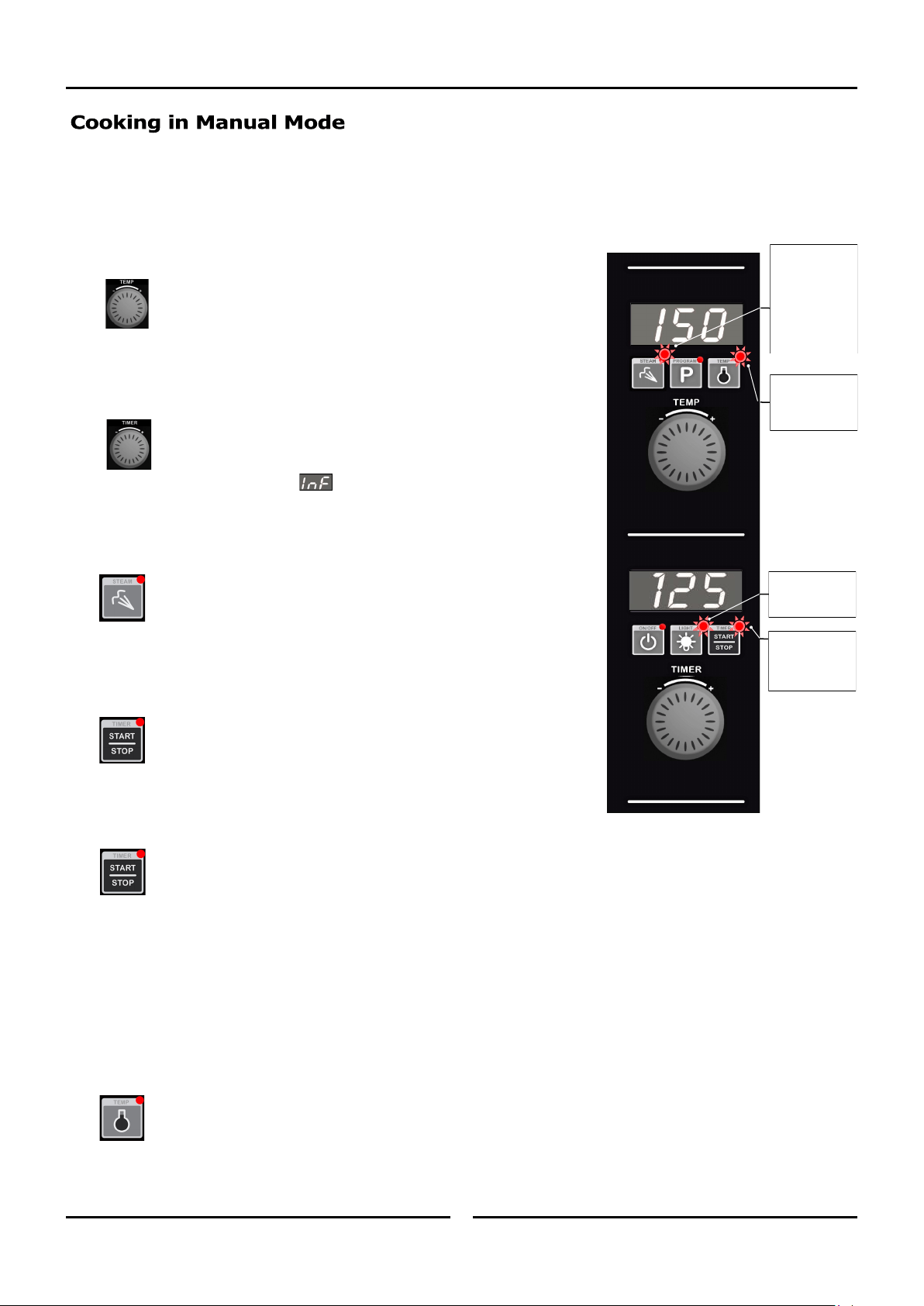
1. SET OVEN TEMPERATURE.
Rotate ‘Temp’ knob to select temperature required.
+ to increase the temperature (Max. 260°C / 500°F).
- to decrease the temperature (Min. 60°C / 140°F).
The oven will commence heating to the displayed set temperature.
NOTE: The oven can be used without using the timer.
2. SET TIMER.
Rotate ‘Timer’ knob to select time required.
+ to increase the time (Max. 180 minutes).
- to decrease the time (Min. 1 minute).
NOTE: Timer can be set to ‘Infinity’ . If timer is set to ‘Infinity’, timer will
count elapsed time to a max of 999 minutes and elapsed time will be
shown on the Lower Display.
3. SET MOISTURE MODE.
Press and hold ‘Steam’ key for 3 seconds.
Rotate ‘Temp’ knob to select desired moisture level (H-0 to H-5).
Press ‘Steam’ key to confirm settings.
NOTE: Refer to ‘Moisture Mode Settings’ at start of this section for additional
explanation of moisture level adjustments.
4. STARTING TIMER.
Press ‘Timer-Start/Stop’ key to start timer operation. LED will illuminate
to indicate the timer is running.
Opening oven door when timer is operating will pause timer and turn ‘Off’ fan
and heating. Timer LED will flash.
Press and hold ‘Timer-Start/Stop’ key for 3 seconds to cancel timer.
5. CANCELLING ‘TIME UP’ ALARM (COOKING TIME COMPLETED).
When the set Cooking Time is completed, alarm will sound and Lower Display flashes.
- Press ‘Timer-Start/Stop’ key to cancel alarm, oven will continue cooking at Oven Set Temperature. Display will revert to Set
Temperature and Time.
- Alternatively, open oven door to cancel alarm and turn ‘Off’ fan and heating. Close oven door to resume cooking at Oven
Set Temperature. Display will revert to Set Temperature and Time.
NOTE: Any of the above settings can be adjusted during the cooking operation by using the above controls and keys.
• Viewing Actual Oven Temperature. Press ‘Temp’ key during cooking, Oven Actual Temperature will display on Upper
Display for 5 seconds and then will revert to displaying Oven Set Temperature.
‘Steam’ LED will
illuminate when
automated
Moisture Mode is
set (H-1-H-5) or
during each
manual steam
injection in H-0.
‘Light’ LED is
‘On’ when oven
lights are ‘On’.
‘Timer-Start/
Stop’ LED is
steady ‘On’ when
Timer is running.
‘Temp’ LED will
remain ‘On’ until
oven reaches Set
Temperature.
Operation
12 12
On oven start-up the controller defaults to the following settings:-
Oven Temperature is set to 150°C (325°F).
Refer ‘Controller - Operator Settings’ section to change this start-up temperature.
Oven Timer is not set, display shows ‘ - - -’.
Moisture Setting is setting to Manual Injection.
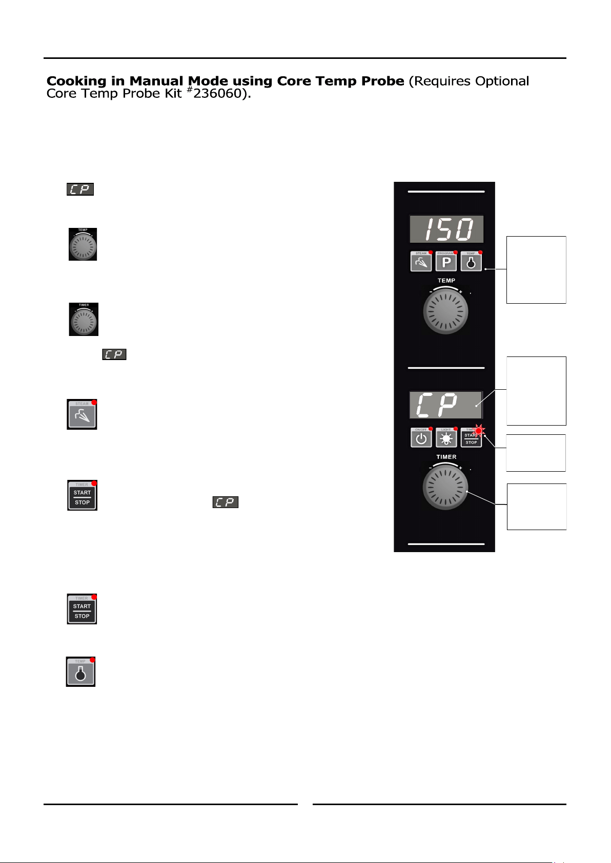
1. CONNECT CORE TEMP PROBE.
Connect Core Temp Probe to connector on lower right side of
control panel, will be displayed on Lower Display.
2. SET OVEN TEMPERATURE.
Rotate ‘Temp’ knob to select temperature required.
+ to increase the temperature (Max. 260°C / 500°F).
- to decrease the temperature (Min. 60°C / 140°F).
The oven will commence heating to the displayed set temperature.
3. SET CORE PROBE TEMPERATURE.
Rotate Timer Knob to set the desired core probe temperature.
+ to increase temperature (Max. 90°C / 194°F).
- to decrease temperature (Min. 50°C / 122°F).
Once Core Probe Set Temperature is set, Lower Display will alternately flash
between and Core Probe Set Temperature.
‘Timer-Start/Stop’ LED is ‘Off’, indicating that cooking has not yet started.
4. SET MOISTURE MODE.
Press and hold ‘Steam’ key for 3 seconds.
Rotate ‘Temp’ knob to select desired moisture level (H-0 to H-5).
Press ‘Steam’ key to confirm settings.
NOTE: Refer to ‘Moisture Mode Settings’ at start of this section for additional
explanation of moisture level adjustments.
5. START CORE TEMP MODE COOKING.
Press ‘Timer-Start/Stop’ key to start Core Temp Mode cooking. ‘Timer-
Start/Stop’ LED is ‘On’ during Core Temp Mode cooking. Lower Display
will alternately flash between and Core Probe Set Temperature
during cooking.
6. CANCELLING CORE TEMP ALARM (CORE TEMP SETTING REACHED - COOKING COMPLETE).
When Core Probe Set Temperature is reached, an alarm will sound and the Lower Display will flash.
- Press ‘Timer-Start/Stop’ key to cancel alarm, oven will continue cooking at Oven Set Temperature. Display will show Oven
Set Temperature and Core Probe Set Temperature.
- Alternatively, open oven door to cancel alarm and turn ‘Off’ fan and heating. Close oven door to resume cooking at Oven
Set Temperature. The display will revert to the Oven and Core Probe Set Temperatures.
NOTE: Any of the above settings can be adjusted during cooking operation by using the above controls and keys.
• Viewing Actual Oven and Core Temperatures. During cooking, press ‘Temp’ key to check Oven Actual
Temperature (Upper Display) and Core Probe Actual Temperature (Lower Display). Actual temperatures will display for 5
seconds before display reverts to show Oven Set Temperature (Upper Display) and Core Probe Set Temp (Lower Display).
• Exiting Core Temp Cooking Mode. Disconnect Core Probe from connector on lower right side of control
panel. Lower Display and ‘Timer’ knob will revert to normal Timer Mode operation.
‘Timer-Start/
Stop’ LED is ‘On’
when Cook Mode
in Progress.
In Core Temp
Mode, pressing
‘Temp’ key will
also display Core
Probe Actual
Temperature on
Lower Display.
In Core Temp
Mode, the ‘Timer’
knob is used to
set Core Probe
Temperature.
In Core Temp
Mode, the Lower
Display will
alternate
between ‘CP’ and
the Core Probe
Set Temperature.
Operation
13 13
The oven can be pre-programmed with up to 20 Programs; each program can contain a maximum of 3 stages. When you receive your oven,
the controller is not pre-programmed.
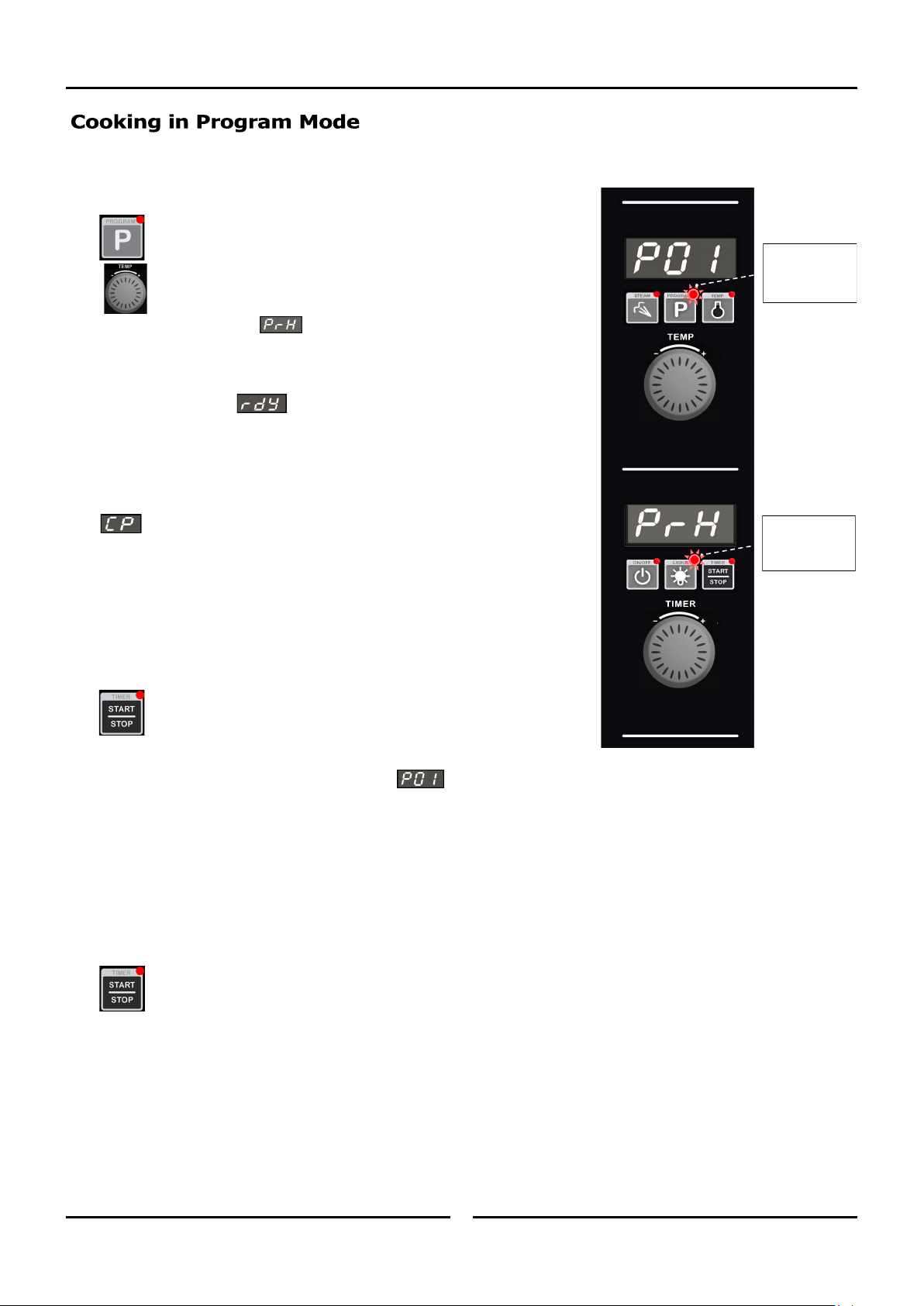
1. SELECTING A PROGRAM.
Press ‘Program’ key.
Upper Display will show program number selected.
+ to scroll forward through programs.
- to scroll backward through programs.
Lower Display will show , oven is ‘Pre-Heating’.
Program cannot be started until pre-heating is completed.
2. OVEN READY.
Lower Display will show when oven is up to pre-heat temperature and an
alarm will sound.
Load product into oven.
3. CONNECT CORE TEMP PROBE (IF REQUIRED).
Connect Core Temp Probe to connector on lower right side of control panel,
will be displayed on Lower Display.
NOTE: A Core Temp Probe can be used as part of a multi-stage cooking program.
If a program reaches a Stage that requires a Core Temp Probe and no Core
Temp Probe is connected, an error alarm will sound and ‘CP’ will flash on
Lower Display. The program is automatically paused until the Core Temp
Probe is connected. Once the probe is connected to the control panel and
inserted into the food product, press the ‘Timer-Start/Stop’ key to resume
the program.
4. START PROGRAM.
Press ‘Timer-Start/Stop’ key to start cooking program.
• Pressing and holding ‘Timer-Start/Stop’ key for 3 seconds will cancel the
program and return to the Preset Program.
During Program Operation the Upper and Lower Displays will show the following:-
• Upper Display shows Program Number, e.g.
• Lower Display will show either,
- Total Time Remaining in Program.
OR
- Total Elapsed Time of Program (if any Program Stages are set to CP or InF).
OR
- Alternate between ‘CP’ and Core Probe Set Temp (if presently in a Core Probe Stage).
5. CANCELLING PROGRAM ‘TIME UP’ ALARM (COOKING TIME COMPLETED).
When program is completed, the alarm will sound.
• To cancel alarm, press ‘Timer-Start/Stop’, oven will continue to cook at Oven Set Temperature. Display will revert to
Program Number (Upper Display) and Total Program Time (Lower Display).
• Alternatively, open oven door to cancel alarm and turn ‘Off’ fan and heating. Close oven door to resume cooking at Oven
Set Temperature. Display will revert to Program Number (Upper Display) and Total Program Time remaining (Lower
Display).
‘Program’ LED is
‘On’ when Oven
operating in
Programs Mode.
‘Light’ LED is ‘On’
when oven lights
are ‘On’.
Operation
14 14
NOTE: Adjustments made during cooking will not be saved to the program.
A. VIEWING STAGE NUMBER AND STAGE TIME REMAINING.
To view the Program and Stage numbers on the Upper Display, e.g. 3.1 = Program 3, Stage 1, and the Total Time Remaining in Stage
remaining on the Lower Display:
- Press ‘P’ key during Program Cooking.
OR
- Turn Timer knob in either direction.
• Upper Display will show Program and Stage, e.g.
• Lower Display will show either,
- Total Time Remaining in Stage.
OR
- Total Elapsed Time of Stage (if Stage is set to ‘InF’).
OR
- Core Probe Set Temp (if Stage is set to ‘CP’).
OR
- Alternate between ‘CP’ and Core Probe Set Temp (if presently in a Core Probe Stage).
Display will revert back to Overall Display after 5 seconds.
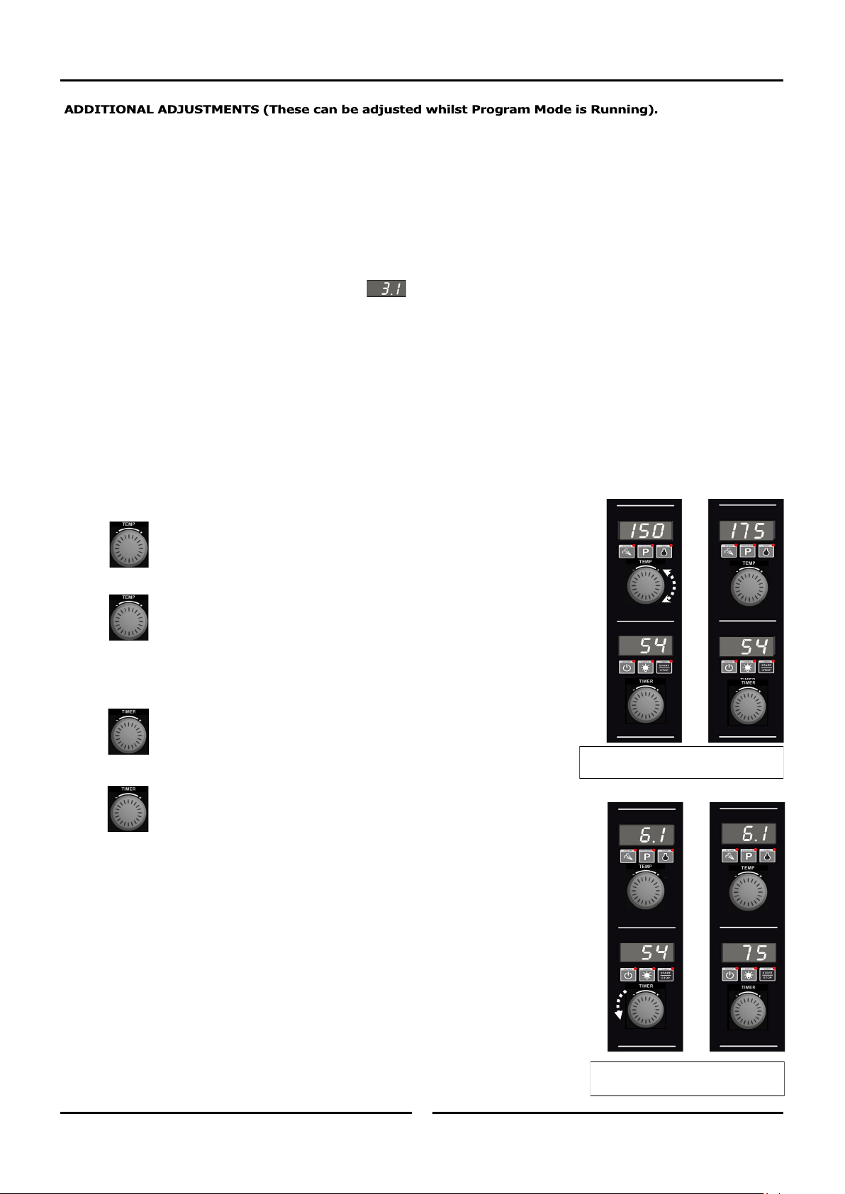
B. USING ‘TEMP’ KNOB DURING PROGRAM COOKING.
• VIEWING SET TEMPERATURE
Turn ‘Temp’ knob (in either direction) to display Set Temperature of Current
Stage on Upper Display. Display will revert back to Overall Display after a
5-second delay.
• ADJUSTING SET TEMPERATURE
Hold ‘Temp’ knob in either direction for 3 seconds will enter ‘Temp Edit Mode’
where ‘Temp’ knob can be used to temporarily adjust temperature for the current
stage. Controller will update the Temperature and exit ‘Temp Edit Mode’ after a
5-second delay.
C. USING ‘TIMER’ KNOB DURING PROGRAM COOKING.
• VIEWING STAGE NUMBER AND REMAINING TIME
Turn ‘Timer’ knob (in either direction) to switch the display from Overall
(Program, Total Time remaining) to Current Stage-in-Progress (Stage, Stage
Time Remaining). Display will revert to Overall display after a 5-second delay.
• ADJUSTING REMAINING TIME / ADJUSTING CORE PROBE SET TEMP
Hold the ‘Timer’ knob in either direction for 3 seconds to enter ‘Timer Edit Mode’
where ‘Timer’ knob can be used for temporary adjustment of either:
- Core Probe Set Temperature.
OR
- Stage Time remaining.
The controller will update the value and exit ‘Timer Edit Mode’ after a 5-second delay.
Time remaining can be adjusted between 0-180 minutes, but cannot be set to ‘InF’ or
‘CP’.
Core Probe Set Temp can be set between 50-90°C (122-194°F).
NOTE: Any changes will only apply to the current stage. Any following stages will
revert to the programmed settings.
Here Oven Set Temperature has been
increased from 150 to 175°C (325 to 350°F).
Here Core Probe Temperature has been
increased from 54 to 75°C (129 - 167°F).
Operation
15 15
D. CHANGING THE MOISTURE SETTING.
Press and hold ‘Steam’ key for 3 seconds.
Rotate ‘Temp’ knob to select desired moisture level (H-0 to H-5).
Press ‘Steam’ key to confirm settings.
NOTE: Refer to ‘Moisture Mode Settings’ at start of this section for additional explanation of moisture level adjustments.
E. VIEWING ACTUAL OVEN TEMPERATURE / ACTUAL CORE PROBE TEMPERATURE.
Press ‘Temp’ key during cooking. Oven Set Temperature will display on Upper Display for 2 seconds, then Actual Temperature
will display on Upper Display for 2 seconds. At the same time, Actual Core Probe temperature will display on Lower Display
for 4 seconds. After 4 seconds, controller will revert to displaying the program number.
F. ADDING MORE TIME TO A STAGE WHEN THE END OF STAGE ALARM IS SOUNDING.
At the end of a stage, provided that ‘ALr’=On, an end of stage alarm will sound for 1 minute before automatically progressing on to the
next stage of the program. While alarm is sounding, additional cooking time can be added to the stage that has just finished.
Rotate and hold ‘Timer’ knob for 3 seconds to enter Timer Edit Mode and add time to the stage.
When the length of time required has been added, either;
- Press ‘Timer-Start/Stop’ key to resume the stage,
OR
- Wait for the auto-resume feature to progress the oven on to the next stage, 1 minute after alarm initially sounded.
When the additional time has run out, the end of stage alarm will sound for a second time. Either press ‘Timer-Start/Stop’ key
to progress on to the next stage, or let the program automatically progress on to the next stage after 1 minute of inactivity.
G. TURNING THE LIGHTS ‘ON/OFF’.
Whenever the oven is ‘On’ the ‘Light’ key is used to turn the oven lights ‘On/Off’. To extend bulb life, an auto time-out can be
pre-set to switch oven lights ‘Off’ after a set length of time. The factory default for time-out is ‘Off’ (‘0’, ie lights remain ‘On’
until light key is pressed again). This time-out can be activated by setting the operator settings L-0 from 1-60 minutes.
NOTE: Any changes will only apply to the current stage. Following stages will revert to the programmed settings.
Programming
16
The oven can be pre-programmed with up to 20 Programs; each program can contain a maximum of 3 stages. When you receive your oven,
the controller is not pre-programmed. To set programs, carry out the following for each program required:
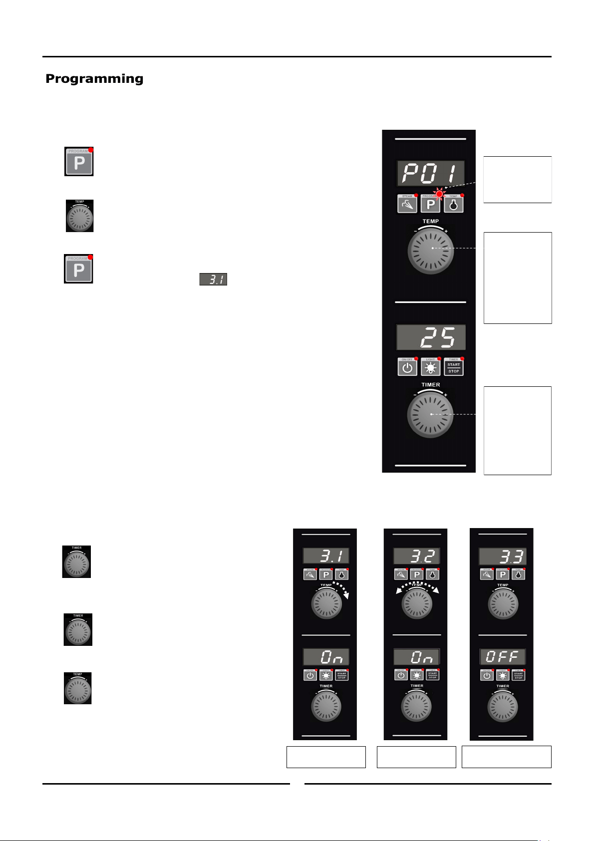
1. SELECT PROGRAMS MODE.
Press ‘Program’ key to enter Programs Mode.
‘Program’ LED will illuminate.
2. SELECT PROGRAM REQUIRED (P01 - P20).
Rotate ‘Temp’ knob to the program required.
Upper Display will show program selected.
3. ENTER PROGRAMMING MODE.
Press and hold ‘Program’ key until a beep is heard, indicating entry into
Programming Mode. Upper Display shows program and stage numbers
eg
.
= Program 3, Stage 1.
‘Program’ LED will flash whilst in Programming Mode.
4. SELECT STAGE TO PROGRAM.
NOTE: If Multi-Stage Cooking is disabled, (Parameter ’StG’ - refer to section
‘Controller Operator Settings’) skip to Step 6 to continue programming
otherwise continue as below and overleaf.
All active stages and the first inactive stage are visible and can be accessed by
rotating the ‘Temp’ knob to scroll through the stages. When editing a program for
the first time, only the first stage will be visible and it will be ‘Off’ by default.
Setting parameters for a stage changes its state from ‘Off’ to ‘On’ (activates the
stage).
• To Turn a Stage ‘On’.
Either - Rotate ‘Timer’ knob clockwise to select
‘On’.
Or - Press ‘P’ key and program stage settings.
(Setting parameters for a stage automatically
changes its state to ‘On’).
• To Turn a Stage ‘Off’.
Rotate ‘Timer’ knob anti-clockwise to select ‘Off’.
NOTE: Only the last active (‘On’) stage can
be turned ‘Off’.
Rotate ‘Temp’ knob:-
‘+’ to advance one stage.
‘-’ to go to the previous stage.
‘Program’ LED is ‘On’
when Oven is
operating in
Programs Mode.
In Program Mode,
‘Temp Knob’ is
used to select:-
Program.
Stage.
And to set:-
Cook Temperature.
Moisture Level.
In Program Mode,
‘Timer’ Knob is
used to select:-
Core Probe.
And to set:-
Program Time.
Core Probe
Temperature.
Program 3, Stage 1.
STATE: ON.
Program 3, Stage 2.
STATE: ON.
Program 3, Stage 3.
STATE: OFF (ie; Inactive).
Programming
17
5. CONFIRM STAGE TO EDIT.
Press ‘Program’ key to begin editing a program and stage displayed on the Upper Display.
6. SET OVEN TEMPERATURE.
*Upper Display flashing*
Rotate ‘Temp’ knob to select temperature required.
+ to increase the temperature (Max. 260°C / 500°F).
- to decrease the temperature (Min. 60°C / 140°F).
Press ‘P’ key to confirm temperature setting. Controller will step to Cook Time / Core Temp Probe setting.
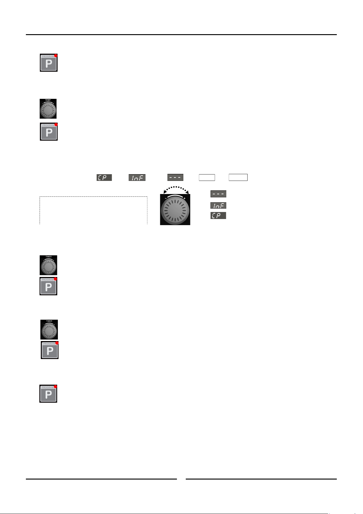
7. SET COOK TIME / CORE TEMP PROBE.
*Lower Display flashing*
The ‘Timer’ knob can be used to select Core Temp Probe or a Cook Time option.
• By setting a Cook Time, the stage will be governed by Oven Temperature, Timer, Moisture setting.
Rotate ‘Timer’ knob to select time required.
+ to increase Cook Time (Max. 180 minutes).
- to decrease Cook Time (Min. 1 minute).
Press ‘P’ key to confirm Timer setting and advance to setting Moisture setting.
• By setting Core Temp Probe (CP), the stage will run at a set Oven Temperature, Moisture Mode until the actual core
temperature reaches the pre-set core probe temperature value. Refer to the ‘Cooking in Manual Mode with Core Probe’ Section for
instructions on cooking with the Core Probe fitted. Turn and hold timer knob until lower display shows ‘CP’. Controller will step to
setting Core Probe Temperature. Core Probe Temperature value is displayed on Lower Display.
Rotate ‘Timer’ knob to select temperature required.
‘+’ to increase Core Probe Temperature (Max 90°C / 194°F).
‘-’ to decrease Core Probe Temperature. (Min 50°C / 122°F).
Press ‘P’ key to confirm Core Probe Temp Setting. Controller will step to Moisture setting.
• By setting Infinite Time setting (‘InF’), Oven counts time upwards up to a limit of 999 minutes. The Infinite (‘InF’) timer
option is only available as an option when setting the last stage of a program. If the ‘InF’ timer option is programmed, no stages
after the ‘InF’ stage will be available / visible. Turn ‘Off’ all stages that come after a given stage in order to set an ‘InF’ timer for
that stage.
Press ‘P’ key to confirm infinite time ‘InF’ setting and advance to setting Moisture setting.
= Stage has been set to ‘OFF’.
= Infinity Time Setting.
= Core Temp Probe (optional extra).
Time = From 1 minute to 180 minutes.
Turn and Release Timer Knob to change
selection.
Hold Knob to Fast Forward Fast Reverse.
1 Min
180 Mins
Programming
18
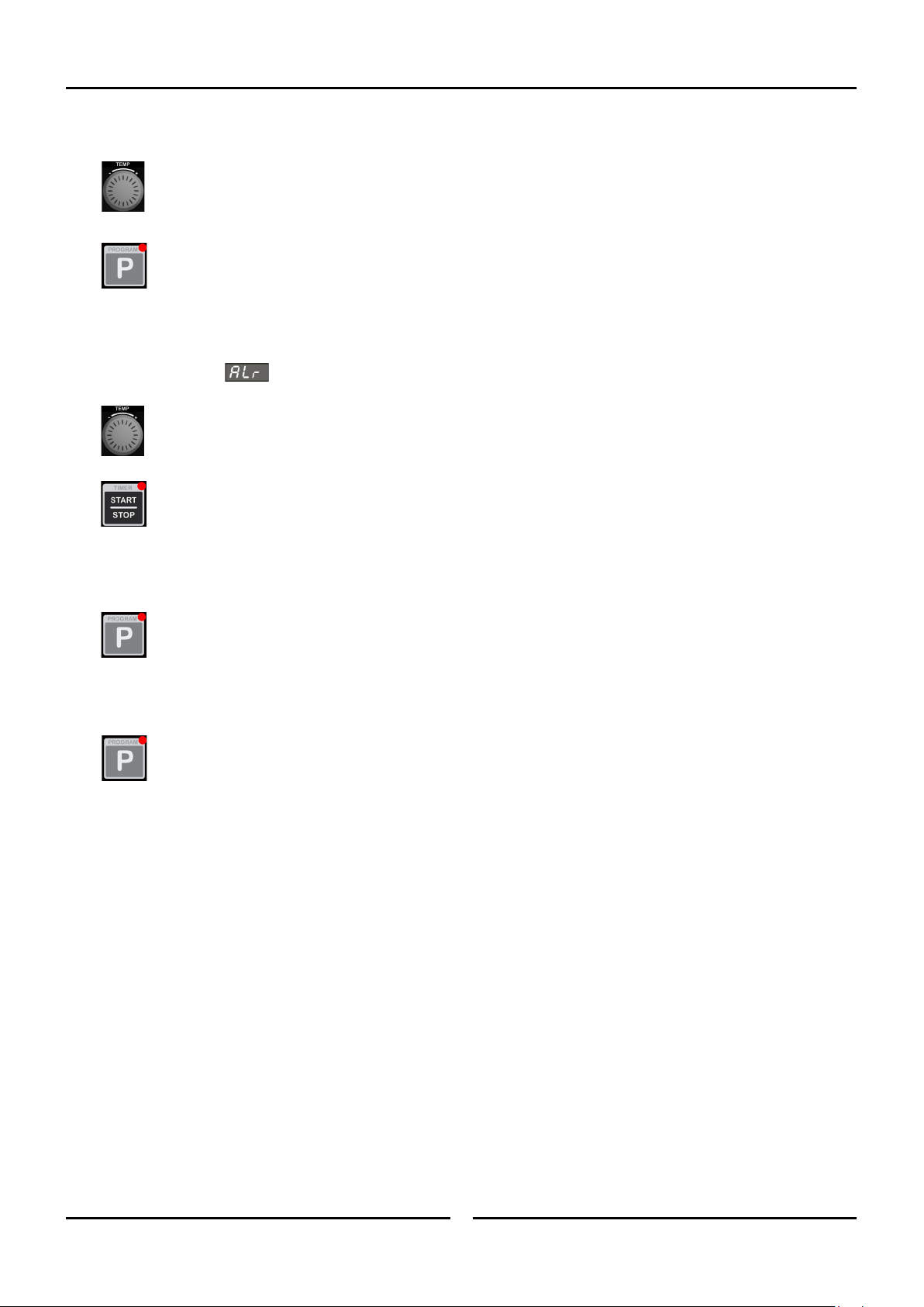
8. SET MOISTURE OPTION (H-0 - H-5).
*Upper Display flashing*
Rotate ‘Temp’ knob to select Moisture setting required.
‘+’ to increase moisture setting.
‘-’ to decrease moisture setting.
(Refer to Operation section, ‘Moisture Mode Settings’, for additional explanation of moisture level adjustment).
Press ‘P’ key to confirm Moisture setting. Controller will step to Alarm for End of Stage setting.
NOTE: If Multi-Stage Cooking is disabled, (Operator setting ’StG’ - set to ‘no’), the controller will exit the Programming
Mode after the ‘P’ key is pressed to confirm moisture setting.
9. SET ALARM FOR END OF STAGE (‘ON-OFF’).
Upper Display shows
*Lower Display flashing with current alarm setting*
Rotate ‘Timer’ knob to select desired alarm state which will be shown on the Lower Display.
‘ON’ - Alarm sounds at completion of the cooking stage, the program is paused awaiting user action. Without any input, the
program will automatically resume after 1 minute.
- Press ‘Timer-Start/Stop’ key to stop the alarm, resume cooking and to continue to the next cooking stage.
OR
- Open oven door to stop alarm. Close door and press ‘Timer-Start/Stop’ key to continue cooking and to continue on to the
next cooking stage.
‘OFF’ - Oven continues on to the next cooking stage without sounding an alarm.
NOTE: Regardless of the setting applied to the last stage of the program, a Cook Time Completed Alarm will sound to indicate the
end of the program.
Press ‘P’ key to confirm alarm option. Alarm will sound to confirm that all stage parameters have been set.
Repeat Step 1 to Step 9 to program additional stages.
10.EXIT PROGRAMMING MODE.
Press and hold ‘P’ key for 3 seconds until alarm sounds to exit the Programming Mode.
USB Export / Import
19
The Oven controller is equipped with USB connectivity, through the USB port located on the lower right hand side of the control panel.
The set of programs, P01 - P30, stored in the controller memory can be:
• Written to a USB memory stick (Export).
• Replaced with a set of programs located on the USB stick (Import).
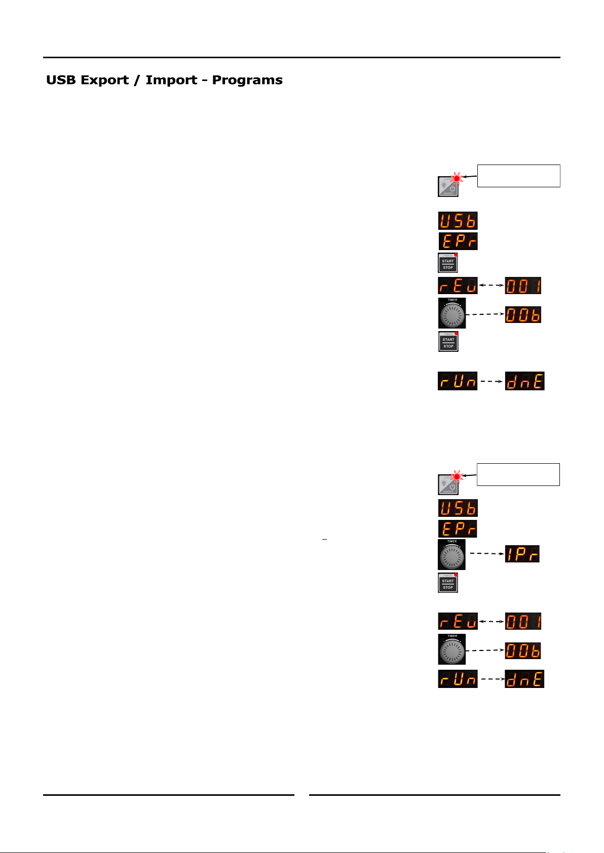
1. To export the set of programs from the controller to the USB stick:
• Ensure the oven is in ‘Standby Mode’ – ‘On / Off’ LED is lit.
• Insert a USB memory stick into the USB port.
• Upper display will show ‘USB’ and lower display will show ‘EPr’ (Export Programs).
• Press ‘Start / Stop’ button.
• Lower display will alternate between ‘rEv’ and ‘001’ (Revision Number e.g. 000 to 999).
(The set of programs can be given a different/new revision number at this point)
• Rotate ‘Timer’ Knob to select revision number required.
• Press ‘Start / Stop’ button to copy programs from controller to USB stick.
If an error message (Err, Er1 or Er2) appears in lower display, refer to
section ‘Fault Finding’
• Lower display will show ‘rUn’, followed by ‘dnE’ once copying is done.
• Remove USB memory stick from USB port.
• Controller will go back to ‘Standby Mode’.
The export feature is useful for backing up the set of programs created in the controller,
creating a copy of the set of programs to apply to another oven, and for editing programs
externally.
2. To import the set of programs to the controller from the USB stick:
• Ensure the oven is in ‘Standby Mode’ - ‘On / Off’ LED is lit.
• Insert a USB memory stick, containing at least one ‘MPRGRXXX.csv’ file into the USB port
(See Section ‘Import / Export Files’).
• Upper display will show ‘USB’ and lower display will show ‘EPr’ (Export Programs).
• Rotate ‘Timer’ knob to change to ‘IPr’ on lower display (Import Programs).
NOTE: IPr will not show on display if a ‘MPRGRXXX.csv’ file is not present.
• Press ‘Start / Stop’ button to copy programs from USB stick to controller.
• If more than one file is present, i.e. MPRGR001, MPRGR002…, the option to select between
these will appear:
• Lower display will alternate between ‘rEv’ and ‘001’ (Revision Number e.g. 000 to 999).
• Rotate ‘Timer’ Knob to select revision number required.
(A maximum of 10 revisions on the USB Stick will be selectable).
• Lower display will show ‘rUn’, followed by ‘dnE’ once copying is done.
• Remove USB memory stick from USB port
• Controller will go back to ‘Standby Mode’.
The import feature is useful for restoring a backed up set of programs, copying programs from another oven, and for loading
programs edited externally.
‘ON / OFF’ LED is ‘On’
when oven is in
‘Stand-By’ Mode.
‘Timer-Start / Stop’ LED
is ‘On’ when oven is in
’Stand-By’ Mode.
USB Export / Import
20
With the USB connectivity, it is also possible to export / import the parameters that determine the functions of the oven.
The export function described under ‘USB EXPORT / IMPORT – PROGRAMS’, also exports the parameter file ‘PARAM.csv’, so the
process is almost identical:
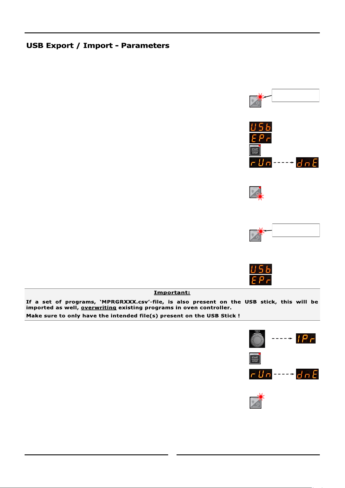
1. To export the Parameters from the controller to the USB stick:
• Ensure the oven is in ‘Standby Mode’ - ‘On / Off’ LED is lit.
• Insert a USB memory stick into the USB port.
• Upper display will show ‘USB’ and lower display will show ‘EPr’ (Export Programs).
• Press ‘Start / Stop’ button to copy programs from controller to USB stick.
• Lower display will show ‘rUn’, followed by ‘dnE’ once copying is done.
• Remove USB memory stick from USB port.
• Controller will go back to ‘Standby Mode’.
The export feature is useful for backing up the parameters in the controller, or creating
a copy of the set of parameters to apply to another oven.
2. To import the set of parameters from the USB stick to the controller:
• Ensure the oven is in ‘Standby Mode’ - ‘On/Off’ LED is lit.
• Insert a USB memory stick, containing a ‘PARAM.csv’ file, into the USB port
(see Section ‘Import / Export - Files’).
• Upper display will show ‘USB’ and lower display will show ‘EPr’ (Export Programs).
• Rotate ‘Timer’ knob to change to ‘IPr’ on lower display (Import Programs).
• Press ‘Start/Stop’ button to copy parameters from USB stick to controller.
• Lower display will show ‘rUn’, followed by ‘dnE’ once copying is done.
• Remove USB memory stick from USB port.
• Controller will go back to ‘Standby Mode’.
The import feature is useful for restoring a backed up set of parameters, or applying a copy of parame-
ters from another oven.
‘ON/OFF’ LED is ‘On’
when oven is in ’Stand-
By’ Mode
‘Timer-Start / Stop’ LED
is ‘On’ when oven is in
’Stand-By’ Mode
USB Export / Import
21
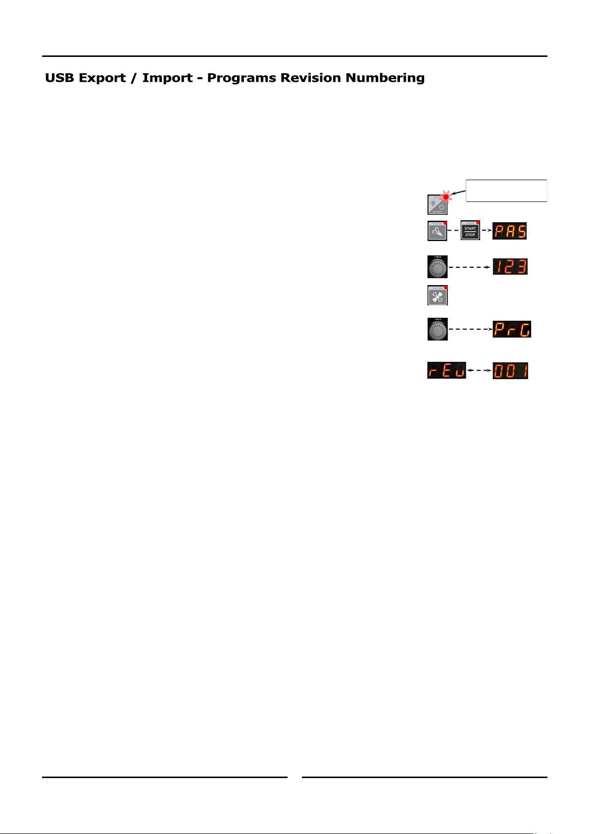
The ‘Set of Programs’, P01-P30, in the controller, has a revision number attached to it, for the purpose of keeping track of changes and
updates to the set of programs stored in the controller or externally on USB Stick / PC.
1. To view the current Program Set Revision Number:
Enter into ‘User Settings’, as described under ‘Controller - User Settings’.
Quick Guide:-
• Place the oven into ‘Standby Mode’ - ‘On / Off’ LED is lit.
• Press and hold ‘Steam’ and ‘Start / Stop’ buttons together until ‘PAS’ is
showing in upper display.
• Rotate ‘Timer’ knob until ‘123’ shows on lower display.
• Press ‘FAN LO’ button.
• Rotate ‘Timer’ knob until parameter ‘PrG’ shows in upper display.
• Lower display will alternate between showing ‘rEu’, (for revision), and the revision
number, i.e. ‘001’.
• The revision number can be edited, if required, in the same manner as other ‘User Settings’.
(Refer to ‘Controller - User Settings’ on the following pages)
Refer section ‘USB Export / Import - Programs’ for further information on using ‘Programs Revision Numbering’.
‘ON/OFF’ LED is ‘On’
when oven is in ’Stand-
By’ Mode
USB Export / Import
22
The files, used for the export / import of the sets of programs and parameters, are separate files:
Set of Programs: MPRGRXXX.csv. (Where XXX is revision number 000-999)
Parameters: PARAM.csv.
With the export command, both files are copied to the USB stick.
It is recommended that a backup copy of the file(s) is kept in a separate storage location and the revision numbering option is used, i.e
‘MPRGR001.csv’. ??
Refer to Section ‘Program Set Revision Numbering’.
With the import command, both the selected programs file and the parameter file are loaded into the controller, if present on the USB stick.
If only programs file(s), MPRGRXXX.csv or Parameter file PARAM.csv, is present on the USB stick, that file alone will be loaded into the
controller.
Controller - Operator Settings
23 23
With the Oven in ‘Stand-By’ Mode (i.e. Power to oven but both displays are blank).
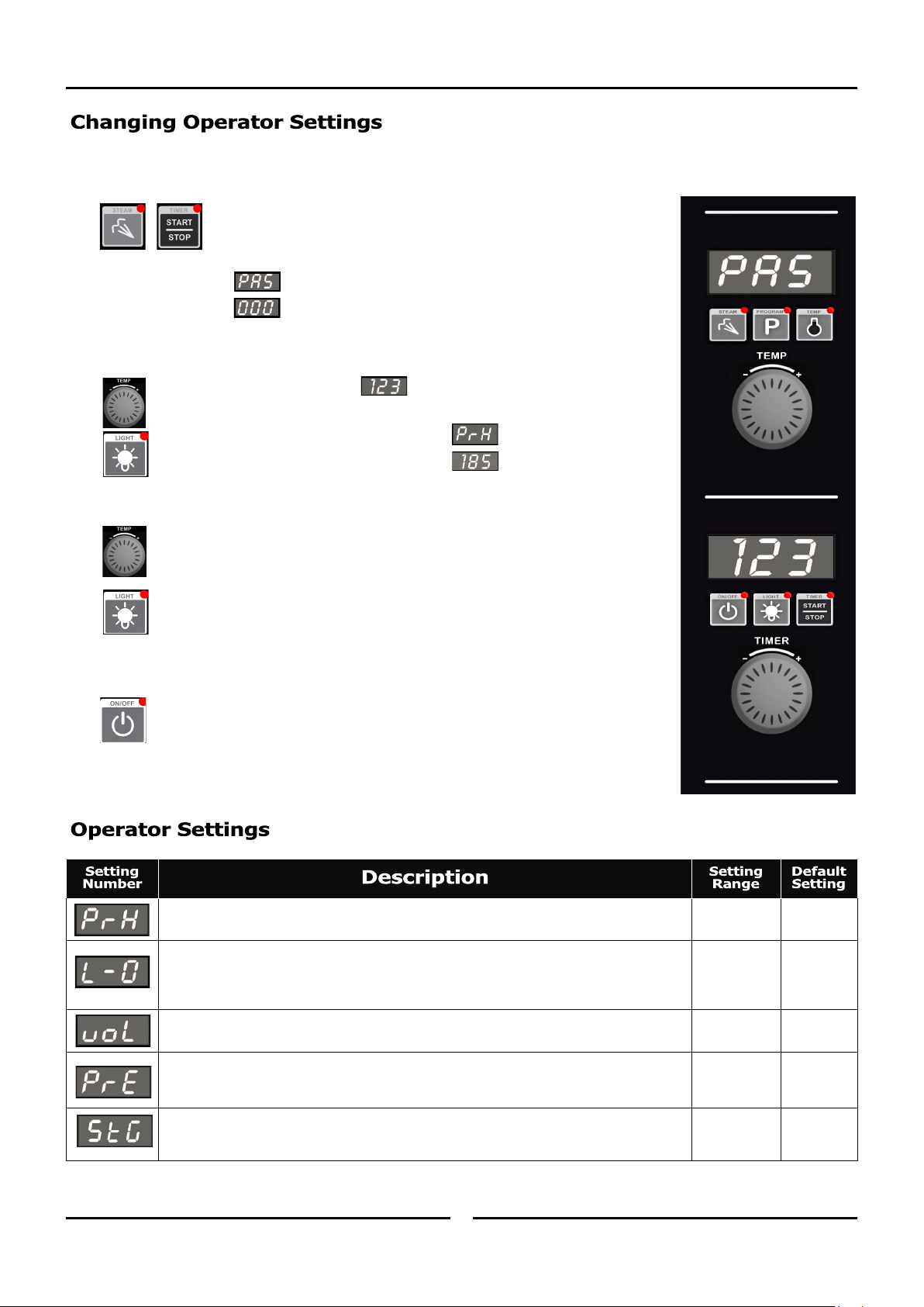
1. ENTERING THE OPERATOR SETTING MODE.
Press and hold 'Steam' and ‘Timer-Start/Stop’ keys together for 3 seconds.
Upper Display will show .
Lower Display will flash .
2. SETTING PASSWORD (OPERATOR PASSWORD - 123).
Rotate ‘Timer’ knob to set password .
Press ‘Light’ key to confirm password.
Upper Display will show one of the setting codes, eg.
Lower Display will show the value of the setting, eg.
3. CHANGING THE SETTINGS.
Rotate ‘Timer’ knob to the setting required.
Press ‘Light’ key to confirm setting required. Lower Display will flash.
While Lower Display is flashing, rotate ‘Timer’ knob to select value required.
Press ‘Light’ key to confirm value. Lower Display will stop flashing.
4. EXITING THE OPERATOR SETTING MODE.
Press ‘On-Off’ key, to exit the Operator Settings Mode and to return to Stand-By Mode.
Oven Pre-Heat; - (Automatic Pre-Heat Temp on oven start-up).
150ºC
(325ºF)
60 - 260°C
140 - 500°F.
Light Auto ‘Off’ Setting Time -
0 = ‘On/Off’.
1 = 1 minute auto ‘Off’.
2 = 2 minutes auto ‘Off’, etc.
2 0 - 60 mins.
Alarm Volume - Can be adjusted to suit operators preference.
5 0 - 10.
Program Pre-Heating Condition - This setting allows for pre-heating ‘Ready’ temperature in
‘Program Mode’ Mode to be set higher than Program Set Temperature. Factory Default Setting
is ‘0’ (Equal to Program Setting).
0
0 - 30°C
0 - 54°F.
Multi-Stage Enable - This setting enables multi-stage programming. Factory default is
‘YES’, multi-stage programming is enabled. Changing this setting this to ‘no’ simplifies
programming and program cooking.
YES ‘YES’ or ‘no’.
Cleaning and Maintenance
24 24
To achieve the best results, cleaning must be regular and thorough.
If any small faults occur, have them looked at promptly. Don't wait
until they cause a complete breakdown.
NOTE:
• Carefully read and follow the safety instructions on the label
of the cleaning product to be used.
• DO NOT use harsh abrasive scouring pads or abrasive
detergents as they could damage the oven.
• Ensure that any detergent or cleaning material has been
completely removed after each cleaning.
To keep your oven clean and operating at peak efficiency, follow the
procedures shown below:-
NOTE:
• If oven usage is very high, the cleaning procedure should be
carried out more frequently.
• Allow the oven interior to cool to approx 50˚C / 120˚F before
commencing cleaning.
Stainless Steel Surfaces
a. Thoroughly clean the exterior surfaces of the oven with, a
damp cloth moistened with a mild detergent solution, or a
soft bristled brush.
b. Baked on deposits or discoloration may require a good
quality stainless steel cleaner. Always apply cleaner when
the oven is cold and rub in the direction of the grain.
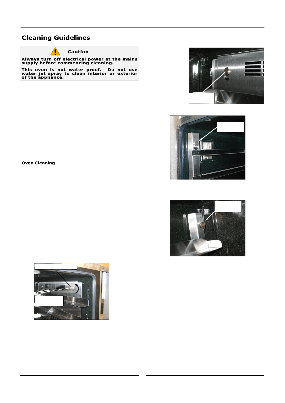
Side Racks Removal
Right Rack / Fan Baffle
a. Undo and remove the rack securing screw securing the
front of the RH side rack. The fan baffle is an integral part
of the RH Side Rack.
b. Lift up and unhook the rear of the rack from the locating
peg at the rear of the oven.
c. Tilt the top of the rack inwards and lift the rack off the
lower mounting brackets.
Left Rack
a. Lift the LH rack off the front locating peg.
b. Pull the rack forward out of the oven to disengage the rear
of the rack from the rear location peg and remove the rack
from the oven.
c. Clean the racks with a mild anti bacterial detergent and hot
water, using a soft bristled brush.
d. Dry the racks thoroughly with a dry cloth.
R/Hand Rear
Locating Peg
L/Hand Front
Locating Peg
L/Hand Rear
Locating Peg
Unscrew
Anti-Clockwise
Rack Securing Screw
Cleaning and Maintenance
25 25
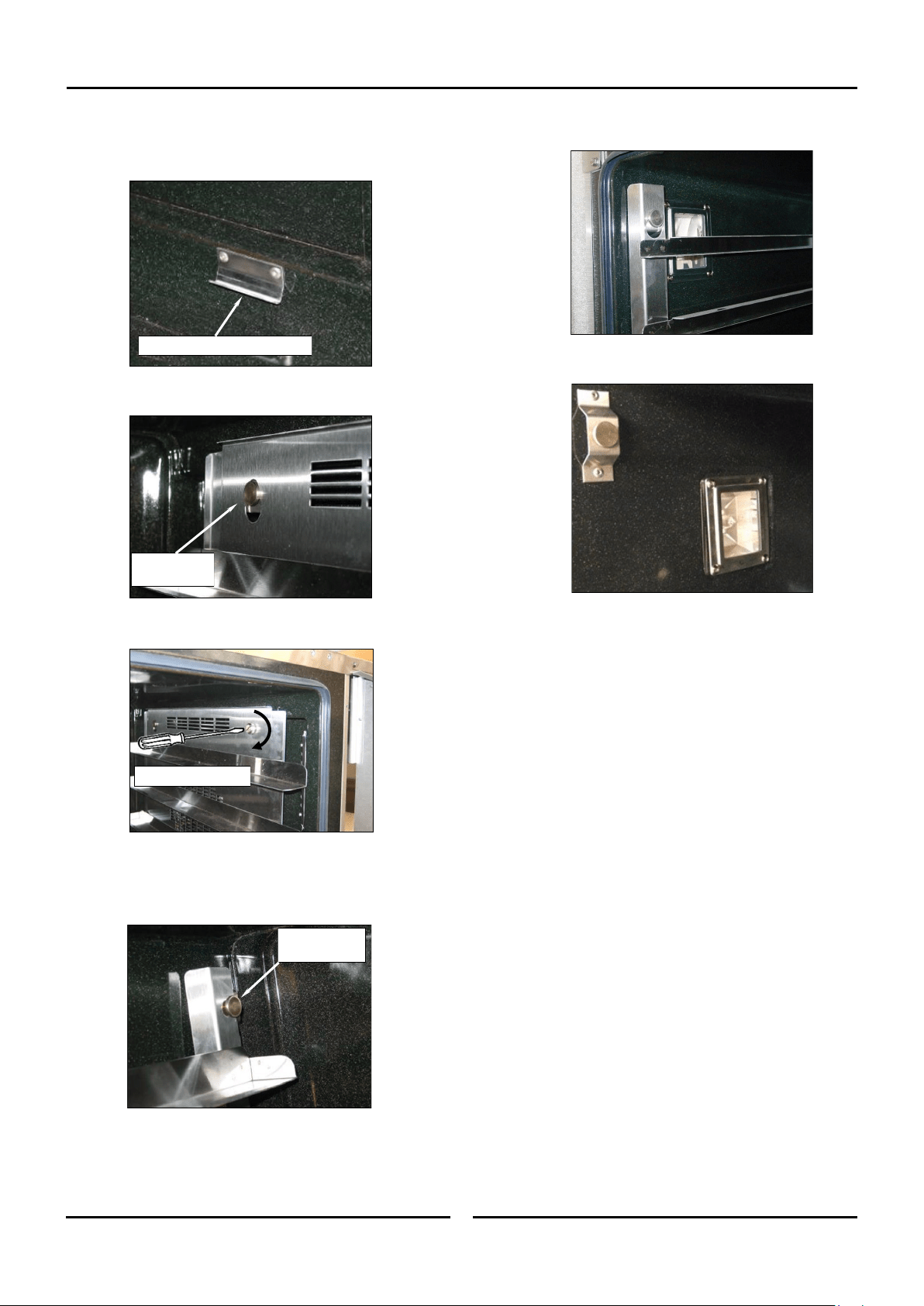
Side Racks Re-Fitting
Right Rack
a. Align the bottom of the rack with the 2 brackets in the
bottom RH side of the oven.
b. Tilt the rack upwards and hook the top rear of the rack on
to the locating peg in the top rear of the oven.
c. Fit and tighten the rack securing screw to secure the front
of the RH rack.
Left Rack
a. Locate the top rear of the rack onto the locating peg at the
top rear LH side of the oven.
b. Locate the top front of the rack over the locating peg at the
top front LH side of the oven.
RH Lower Mounting Brackets
R/Hand Rear
Locating Peg
L/Hand Rear
Locating Peg
Tighten Clockwise
Oven Lamp
a. Remove the LH side rack as shown previously.
b. Wash the glass lens with a soft sponge using warm water
and a detergent solution. Rinse with clean, warm water.
c. Dry the glass lens thoroughly with a dry cloth.
d. Refit LH side rack as shown previously.
Cleaning and Maintenance
26 26
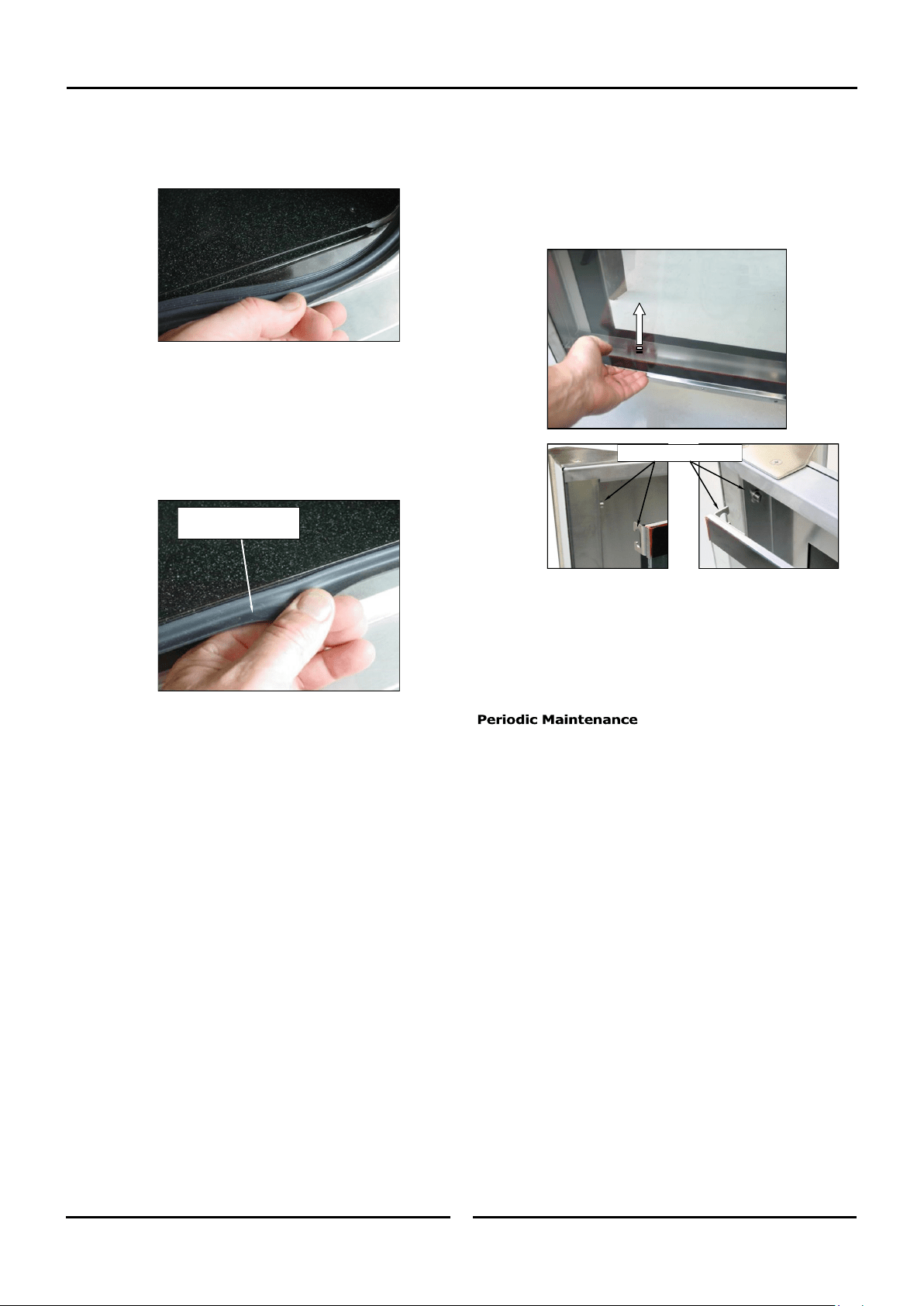
Door Seal
a. To remove the door seal, pull the 1 piece seal forward until
it pulls out of the location groove around the oven. Note
the way the seal is fitted to the oven, with the lip
facing inwards.
b. Check the door seal for wear and damage and replace as
required.
c. Wash the door seal in a sink, taking care not to cut or
damage the seal.
d. Dry the door seal thoroughly.
e. Refit the door seal with lip facing into centre of the oven.
f. Press the door seal into the locating groove in the front face
of the oven until the seal is properly located all around the
oven.
Oven Interior
• Allow the oven interior to cool to approx 50˚C / 120˚F before
commencing cleaning.
a. Remove the oven racks as shown previously.
b. Clean any build up of grease from the oven interior, using a
soft bristled brush with a solution of hot water and a mild
anti bacterial detergent.
c. Dry the oven thoroughly with a soft dry cloth.
d. Clean the oven regularly with a good quality oven cleaner.
Push Seal carefully into
locating channel
Door Glass Cleaning
• Ensure that the oven door is cool before cleaning the oven
door glass.
a. Open the oven door.
b. Lift up the bottom of the inner glass at the centre of the
door to unlock from the inner glass retaining catches and
swing the glass inwards towards the oven.
c. Clean both sides of the inner glass and the inner side of the
outer door glass with a conventional glass cleaner.
d. Dry the oven door thoroughly with a soft dry cloth.
e. Swing the inner glass back towards the outer door.
f. Whilst holding the outer door, lift the inner glass back onto
the locking catches until the inner glass is securely held.
NOTE: All maintenance operations should only be carried
out by a qualified service person.
Controls and mechanical parts should be checked and adjusted
periodically by a qualified service person. It is recommended that
the appliance is serviced every 6 months.
Top Locking Catches
Fault Finding
27 27
This section provides a reference to the more common problems
that may occur during the operation of your oven. This fault finding
guide is intended to help you correct and accurately diagnose
problems with your oven.
When fault finding a problem, always use a process of elimination
starting with the simplest solution and working through to the most
complex. Never overlook the obvious.
You may encounter a problem not covered in this section, please
contact your service provider who will require the following
information:-
• The Model and Serial Number of the oven, can be found on
the Technical Data Plate located on the front right hand side
panel of the oven.
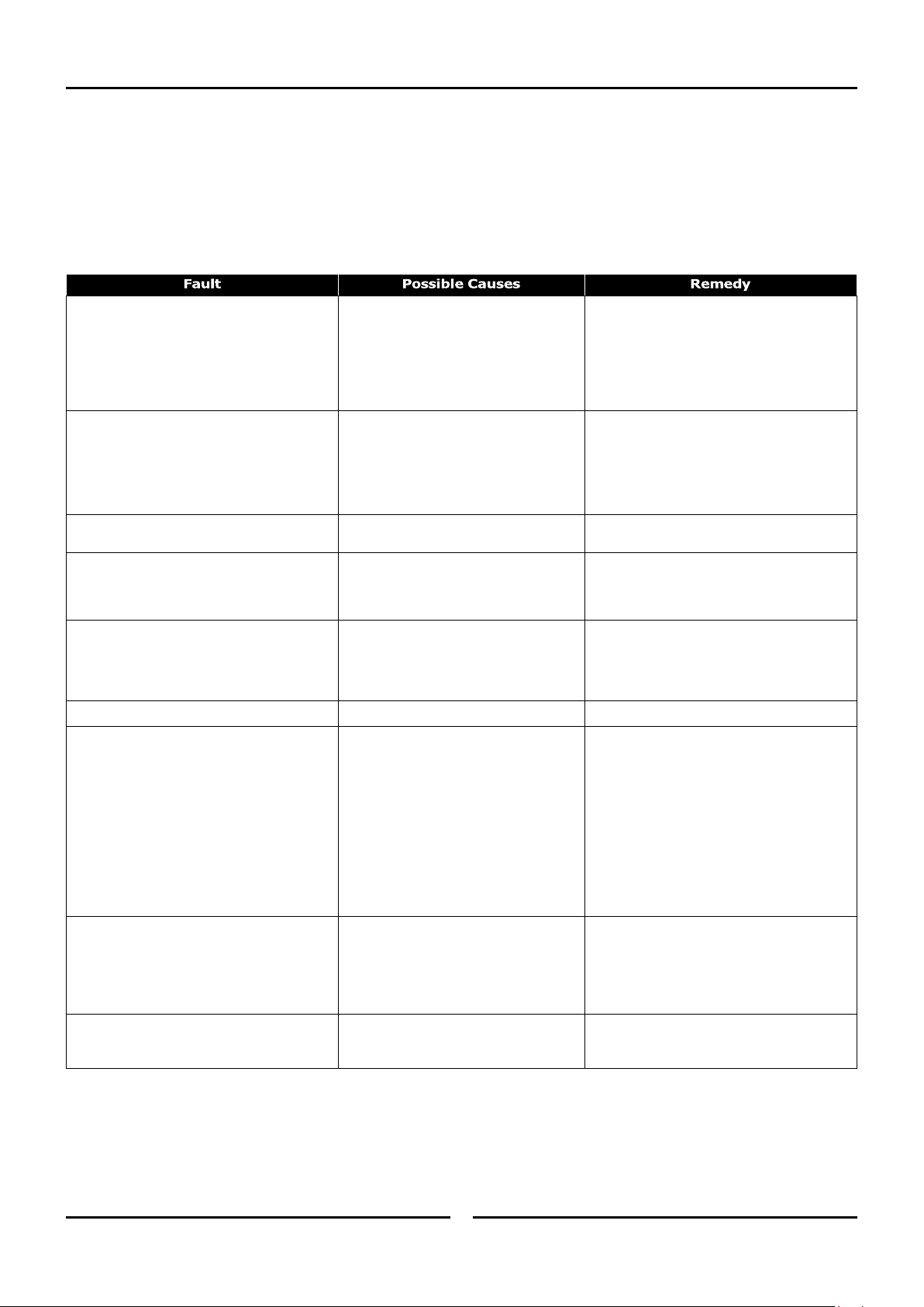
Oven does not operate.
Mains isolating switch, circuit breaker or
fuses are 'Off' at the power board.
Overtemp tripped (No lights, no power
light).
Overtemp faulty.
Digital Controller faulty
Turn 'On'.
Call for service.
Call for service.
Call for service.
Oven Controller operates but:-
No gas supply to oven.
Digital Controller faulty
Door not closed fully (display shows ‘dor’).
Door Switch faulty (display shows ‘dor’).
Check gas supply.
Refer to ‘Digital Controller Fault Codes’. Call for
service.
Close door. (Refer ‘Door does not close fully’).
Call for service.
Oven heats up but fan does not operate.
Fan motor faulty.
Fan or fan motor obstructed.
Call for service.
Call for service.
Oven does not Steam.
Injector Nozzle blocked.
Water Solenoid faulty.
Controller faulty.
Call for service.
Call for service.
Call for service.
Door does not close fully.
Tray in way of door.
Door mis-aligned.
Door seal obstruction.
Correctly position tray in rack.
Re-align door.
Correctly install door seal. (Refer to the
‘Cleaning’ Section).
Oven light not illuminating. Blown bulb. Replace bulb.
Uneven cooking.
Too high a temperature selected.
Oven or racks not level.
Insufficient air space around trays or
baking tins.
Oven overloaded with too much product.
Opening oven door un-necessarily.
Oven door seal damaged or faulty.
Oven vent restricted.
Select a lower temperature.
Check oven racks and level.
Ensure oven racks are spaced to allow air flow
around baking on all shelves.
Re-load oven.
Ensure oven door remains closed during the
baking process.
Check seals and replace if damaged.
Ensure oven vent not blocked or shrouded.
‘Err 001’ on display.
‘Err 003’ on display.
‘Err IGn’ on display.
Oven Probe failure.
Burner Box thermal overload switch
tripped.
Insufficient gas supply.
Room draughts affecting burner.
Ignition circuit fault.
Call for service.
Call for service.
Check gas supply.
Remedy draught problem.
Call for service.
‘CP’ flashing on Lower Display, alarm
sounding, oven program paused.
Core Probe not connected to control panel,
and program requires its use.
Core Probe Faulty.
Connect Core Probe to control panel.
Replace Core Probe.
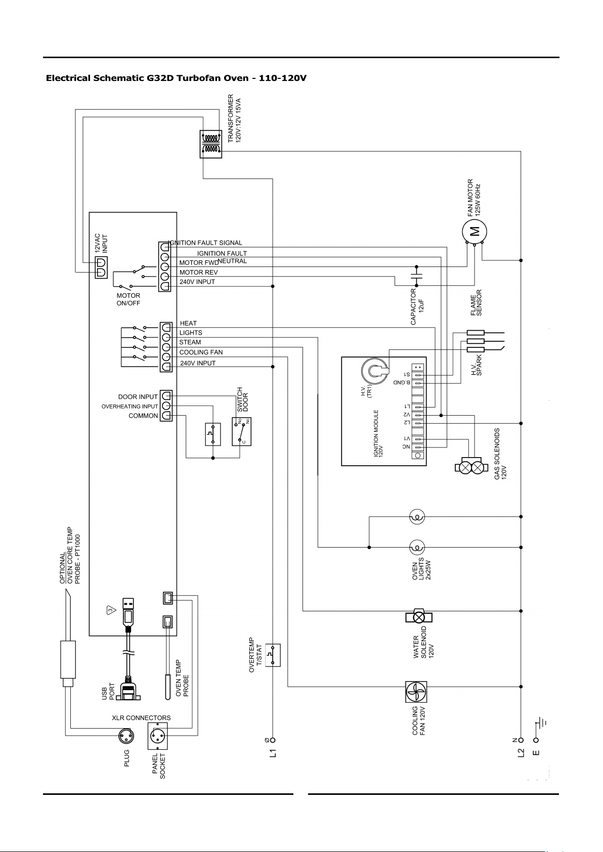
Electrical Schematics
28
THERMAL
SWITCH 125
˚C
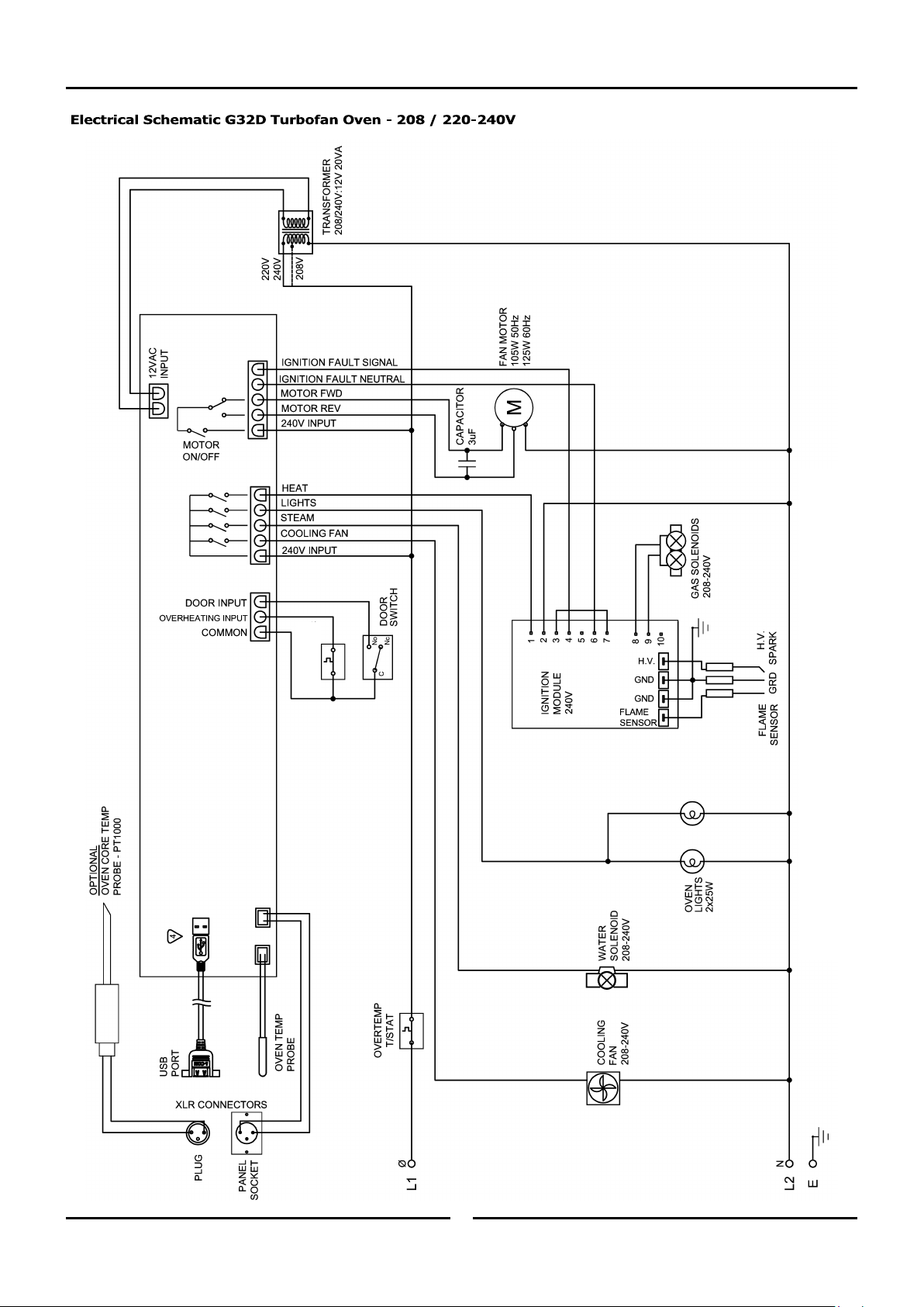
Electrical Schematics
29
THERMAL
SWITCH 125
˚C

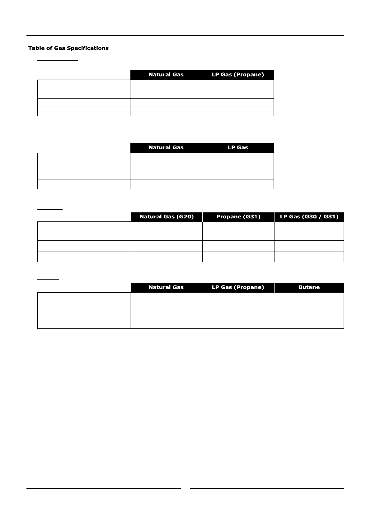
Gas Conversion and Specifications
30
NOTE:
• These conversions should only be carried out by qualified
persons. All connections must be checked for leaks before
re-commissioning the appliance.
• Adjustment of components that have adjustments /settings
sealed (e.g. paint sealed) can only be adjusted in
accordance with the following instructions and shall be
re-sealed before re-commissioning this appliance.
• For all relevant gas specifications refer to the table at the
end of this section.
1. Remove the lower service panel to allow access to the gas
control valve.
2. Unscrew and remove the regulator cover screw from the
regulator incorporated in the gas control.
3. Remove the plastic adjusting screw and regulator spring from
the gas control valve. Replace with correct spring supplied with
the conversion kit.
4. Unscrew and remove the main burner injector and replace with
appropriate item.
5. Connect gas and electrical supplies.
6. Operate oven and adjust the plastic adjust screw on the
regulator to achieve correct pressure at pressure test point
(front RH corner).
7. Refit the regulator cover screw to the gas valve.
8. Conduct full leak test of the converted oven prior to placing it
into operation.
9. Refit the service panels.
On completion of the gas conversion, replace the gas type
identification label with the appropriate label, located at:-
- The rear of the appliance, above the gas connection point.
Before leaving the converted installation;
1. Check all gas connections for leakages using soapy water or
other gas detecting equipment.
2. Check the following functions in accordance with the operating
instructions specified in the ‘Operation’ section of this manual.
• Ensure that all the oven controls operate correctly.
• Ensure that the operating pressure remains correct.
3. Ensure any adjustments done to components that have the
adjustments / settings sealed (e.g. paint sealed), are re-sealed.
NOTE: If for some reason it is not possible to get the
appliance to operate correctly, shut off the gas
supply and contact the supplier of this appliance.
Do not use a naked flame to check for gas leakages.
Main Burner Injector
Cover Screw
Gas Conversion and Specifications
31
- Australia Only:
- New Zealand Only:
- UK Only:
- Export:
Main Burner Injectors 2.80mm. 1.70mm.
Regulator Spring (Colour) Green Spring Blue Spring
Supply Pressure 1.13 - 3.4 kPa. 2.75 - 5.0 kPa.
Operating Pressure 0.75 kPa 2.35 kPa
Main Burner Injectors 2.70mm. 1.70mm. 1.70mm.
Regulator Spring (Colour) Green Spring Blue Spring Blue Spring
Supply Pressure 20 mbar 30 - 37 mbar 28 - 30 mbar
Operating Pressure 10 mbar 25 mbar 24.2 mbar
Main Burner Injectors 2.80mm. 1.70mm.
Regulator Spring (Colour) Green Spring Blue Spring
Supply Pressure 1.13 - 3.4 kPa. 2.75 - 5.0 kPa.
Operating Pressure 0.75 kPa 2.42 kPa
Main Burner Injectors 2.80mm. 1.70mm. 1.70mm.
Regulator Spring (Colour) Green Spring Blue Spring Blue Spring
Supply Pressure 1.13 - 3.4 kPa. 2.75 - 5.0 kPa. 2.75—5.0 kPa.
Operating Pressure 0.75 kPa 2.35 kPa 2.35 kPa
Replacement Parts List
32 32
When ordering replacement parts, please quote the part number and the description as listed below. If the part required is not listed
below, request the part by description and quote model number and serial number which is shown on the Technical Data Plate.
Only genuine authorized replacement parts should be used for the servicing and repair of this oven. The instructions
supplied with the parts should be followed when replacing components.
For further information and servicing instructions, contact your nearest authorized service provider or Turbofan Dealer.
247184 Digital Controller Kit 30D USB-series.
243260 Rotary Encoder and Cable.
243261 Rotary Control Knob.
235700 USB Cable.
234429 Transformer 208/240V x 12VAC SEC 15VA
234430 Transformer 120V x 12VAC SEC 15VA
234460 Cooling Fan 208-230V 50/60HZ
234461 Cooling Fan 115V 50/60HZ
237447K Temperature Probe Kit PT1000
022909 Ignition Electrode Assembly Kit.
234875 Capacitor 3uF, Double 208-240V Models
232552 Capacitor 12uF, 110-120V Models
025400 Overtemp 360°C
232904 Fan Motor 208-240V 50/60HZ
232905 Fan Motor 120V 60HZ
232903 Fan Dia 175mm / 7”
230691 Ignition Module, Brahma CE11U. 208-240V
234459 Ignition Module, 110-120V
019370 Gas Valve G32, 208-240V
234458 Gas Valve G32, 110-120V
241776 120V Solenoid Coil (110-120V Units Only) (Part of Gas Valve).
247449 Thermal Switch 125°C
004952 Burner Assy
032170 Injector 1.70mm LPG
032270 Injector 2.70mm NAT (UK Only)
032280 Injector 2.80mm NAT (Non-UK Only)
235433 Gas Type Conversion Kit AU/NZ/XP Only
235434 Gas Type Conversion Kit UK Only
024802 Door Microswitch
236885 Door Microswitch Gasket
232666 Door Seal
234580 Door Roller Catch
235277 Door Roller Catch Strike
235278 Strike Lock Nut
234930 Door Hinge Assy
234757 Door Inner Glass Assembly
234752 Hinge Pivot Kit
231814 Lamp Bulb G9 25W, Halogen 230V
233884 Lamp Bulb G9 25W, Halogen 120V
236214 Lamp Holder G9 25W
021352 Oven Lamp Lens
242092 Oven Lamp Gasket
020851 Water Solenoid, 208-240V
021617 Water Solenoid, 110-120V
233986 Foot Adjustable 100mm
233649 Oven Rack
234656 Oven Side Rack LH 4-tray
234666 Oven Side Rack RH 4-tray
234658 Oven Side Rack LH 5-tray
234667 Oven Side Rack RH 5-tray
233552 Rack Securing Screw
236060 Core Temperature Probe Kit.
235845 Core Temperature Probe.
235847 Dust Cap - Core Temperature Socket.
236271 Core Temperature Probe Holder.
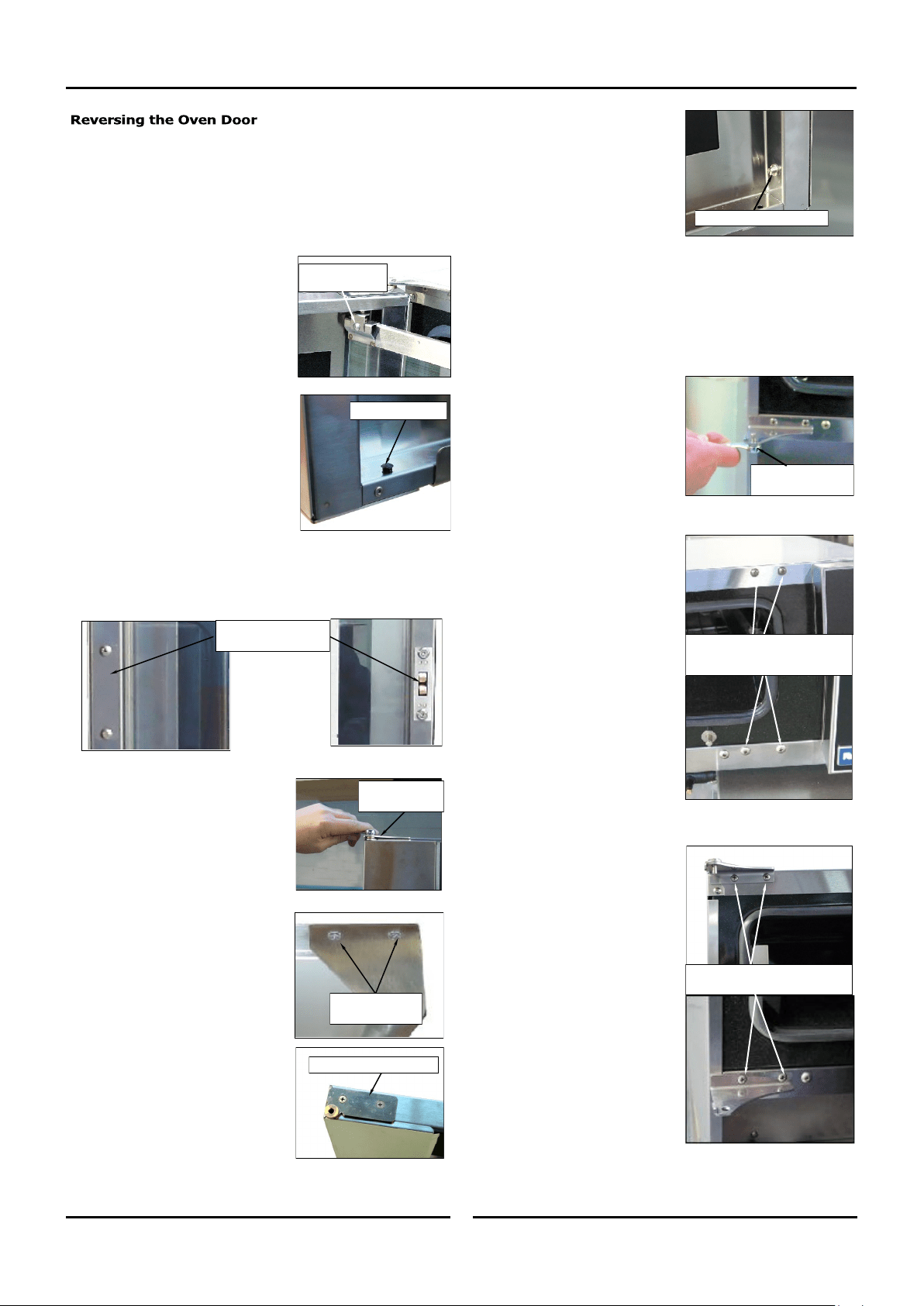
Appendix 1 - Reversing the Oven Door
33 33
Remove Screw
and Retaining
Clip.
• Refit all screw fasteners using a low-mid strength thread
locking adhesive unless otherwise stated.
• Door reversal should only be carried out by a suitably
competent person.
Remove the Oven Door Inner Glass.
1. Open the oven door and open the
door inner glass.
2. Remove screw securing inner glass
retaining clip and remove clip.
3. Lift up inner glass and remove,
ensuring that pivot spacer is
removed from lower inner glass
pivot and retained.
4. Remove black plastic plugs from
top and bottom of door and fit to
holes where inner glass pivots were
removed from.
Remove the Oven Door.
5. Remove the door roller catch and blanking plate from the
inside of the door and swap these over.
6. Whilst supporting door, unscrew
and remove top door pivot bolt from
top door hinge assembly.
7. Remove door and lay on a flat
surface or workbench.
8. Unscrew screws securing the door
handle remove door handle.
9. Remove top door hinge and fit to
bottom opposite corner of door.
10. Remove bottom door hinge and fit
to top opposite corner of door.
Fit Blanking Plugs.
Remove Top
Door Pivot Bolt.
Remove Top Door Hinge
Remove Handle
Securing Screws
Swap Roller Catch and
Blanking Plate over.
11. Remove inner glass latching
studs and fit to opposite side of
door using Loctite 243 or
similar to secure.
12. Turn door handle over and fit to other end of door where
hinges were removed from. Ensure Flat of handle is to the
outside.
Remove Upper and Lower Door Hinges and Door Catch.
13. Remove bottom door pivot bolt
and spacers and fit pivot bolt to
top door hinge assembly (as this
will be swapped over and fitted
to bottom of other side of oven).
14. Remove the 4 blanking screws
from front of oven.
15. Remove Hinge Plate from top of
oven and fit diagonally opposite,
to lower corner.
16. Remove Hinge Plate from
bottom of oven and fit
diagonally opposite, to upper
corner.
17. Fit screws removed at Item 14
above to where hinges were
fitted.
Remove these screws to remove
top and bottom hinges.
Bottom Door Pivot
Bolt and Spacers.
Remove screws top and bottom
and fit to where hinges removed
from.
Remove Latching Studs

Appendix 1 - Reversing the Oven Door
34 34
18. Remove Blanking Screw and Door Catch from front of oven and
swap around (refer ‘Adjusting Door Catch’).
19. Fit door spacers removed at Item 13 previously, to lower hinge
pivot bolt.
Fit the Door.
1. Refit oven door by locating bottom
of door onto bottom hinge plate
pivot bolt and spacers.
2. Fit top of door into top hinge plate
and secure with top pivot bolt.
Fit Inner Glass to Door.
NOTE: It is important to ensure that the inner glass is fitted
correctly and that the glass pivots at the hinge end of
the door and not the handle end.
3. Fit pivot spacer removed at Item 3 on previous page, to the
lower inner glass pivot and locate inner glass lower pivot into
position on inside of door.
4. Locate top pivot of inner glass into
top of door and secure in position
with inner glass retaining clip.
5. Lift inner glass up onto locking catch
to lock glass into position.
Top Door Pivot Bolt.
Inner Glass Locking Catch
Screw and
Retaining Clip.
Check alignment and operation of the door. Ensure that the door is
correctly aligned horizontally and vertically.
1. To align, slacken off the upper and
lower hinge plates and correctly
align the door. Re-tighten both
hinge plates.
2. Check that the roller catch correctly
retains door in the closed position.
3. To adjust, slightly loosen screws
securing roller catch and close the
door. The roller catch will
centralise itself.
4. Open door and tighten roller catch
securing screws.
If the door sealing requires adjustment, carry out the following to
adjust the door catch:-
1. Check that the door seals correctly
when closed, by placing a sheet of
paper between the door and the
seal.
2. Close the door on the paper and
attempt to withdraw the paper by
firmly tugging on the paper. The
paper should just pull out with
some resistance but without
tearing.
3. To adjust the door catch, loosen the locking nut on the door
catch:-
a. If the paper withdraws easily,
screw the door catch ‘In’
by ½ a turn
and repeat the test above until adjusted cor-
rectly.
b. If the paper cannot be withdrawn and the door springs
open,
screw the door catch ‘Out’ by ½ a turn
and
repeat the test above until adjusted correctly.
4. Tighten the locking nut on the door catch.
Slacken these screws to adjust
door vertically - horizontally.
Door Catch
Locking Nut
Blanking Screw