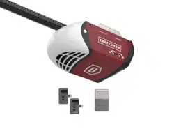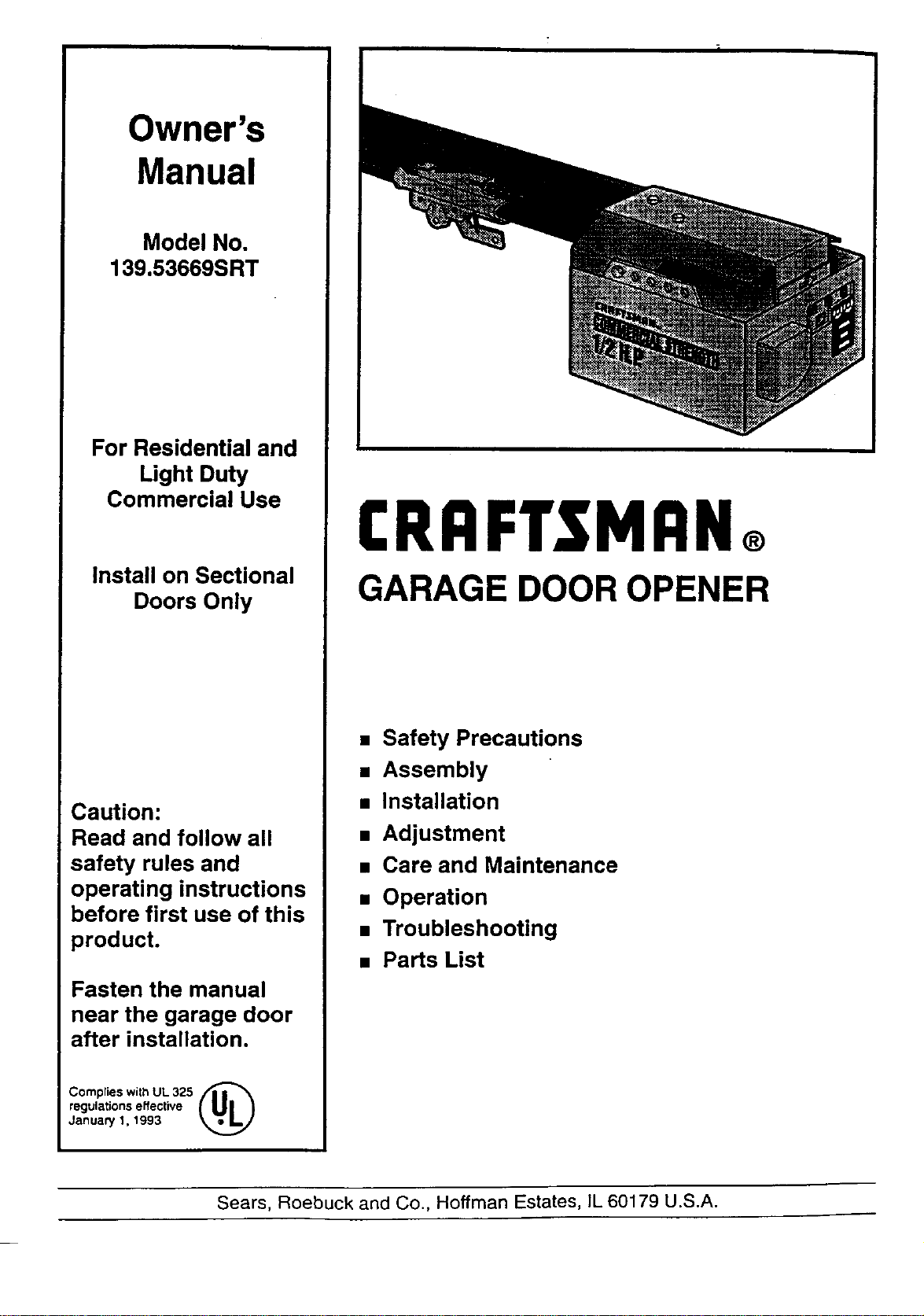
Owner's
Manual
Model No.
139.53669SRT
For Residential and
Light Duty
Commercial Use
Install on Sectional
Doors Only
Caution:
Read and follow all
safety rules and
operating instructions
before first use of this
product.
Fasten the manual
near the garage door
after installation.
Comp(ies with UL 325
regulations effective ( U|
Januae/1, 1993
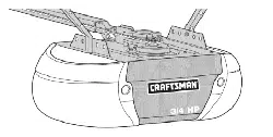
CRRFTSMRN®
GARAGE DOOR OPENER
• Safety Precautions
• Assembly
• Installation
• Adjustment
• Care and Maintenance
• Operation
• Troubleshooting
• Parts List
Sears, Roebuck and Co., Hoffman Estates, IL 60179 U.S.A.
Contents . Page
A review of safety alert symbols............................. 2
You'll need tools ..................................................... 3
Safety information ................................................... 3
Testing your garage door for sticking, binding
and balance .......................................................... 3
Illustration of sectional door installation ................. 4
Carton inventory ..................................................... 5
Hardware inventory ................................................ 6
Assembly section - pages 7- 10
Assemble rail........................................................ 7
Attach chain pulley bracket ................................... 7
Install trolley.......................................................... 8
Fasten rail to opener ............................................. 8
Install chain........................................................... 9
Attach rail support bracket .................................... 9
Tighten the chain ................................................ 10
InstallaUon secUon - pages 10- 23
Installation safety instructions............................. 10
Determine header bracket location..................... 11
Install the header bracket ................................... 12
Attach the rail to header bracket......................... 13
Position the opener ............................................. 14
Hang the opener ................................................. 15
Install the door control ........................................ 16
Install the light ..................................................... 17
Contents Page
Attach emergency release rope and handle ............. 1
Electrical requirememtS ............................................ 18
Safety reversingsensor information ......................... 19
Install the safety reversing sensor ...................... 20, 21
Fasten door bracket .................................................. 22
Connect door arm to trolley....................................... 23
Adjustment section - pages 24 - 26
Travel limitadjustments ............................................ 24
Force adjustments .................................................... 25
Test the safety reversing sensor............................... 26
Test the safety reverse system ................................ 26
Operation safety instructions ...................................... 27
Care of youropener .................................................... 27
Maintenance schedule ................................................ 27
Operation of your opener ........................................... 28
Receiver and remote control programming................. 29
Having a problem?................................................ 30, 31
Repair parts, railassembly ......................................... 32
Repair parts, installation............................................. 32
Repair parts, opener assembly ................................... 33
Accessories ................................................................. 34
Index ........................................................................... 35
How to order repair parts ............................................ 36
Warranty ..................................................................... 36
Start by reviewing these important safety alert symbols
When you see these Safety Symbols on the following pages, they will alert you to the possibility of
serious injury or death if you do not comply with the corresponding instructions. The hazard may
come from something mechanical or from electric shock. Read the instructions carefully.
....................,,: ............................_:_._,_.; ,:_,,,_.=,_,_ _,:_._:_:__ __.,,:,_,_...... .................................................................. ................................_ _
Mechanical Electrical
When you see this Safety Symbol on the following pages, it will alert you to the possibility of damage
to your garage door and/or the garage door opener if you do not comply with the corresponding
instructions. Read the instructions carefully.
This garage door opener is designed and tested to offer safe service provided it is installed, operated,
maintained and tested in strict accordance with the safety instructions contained in this manual.
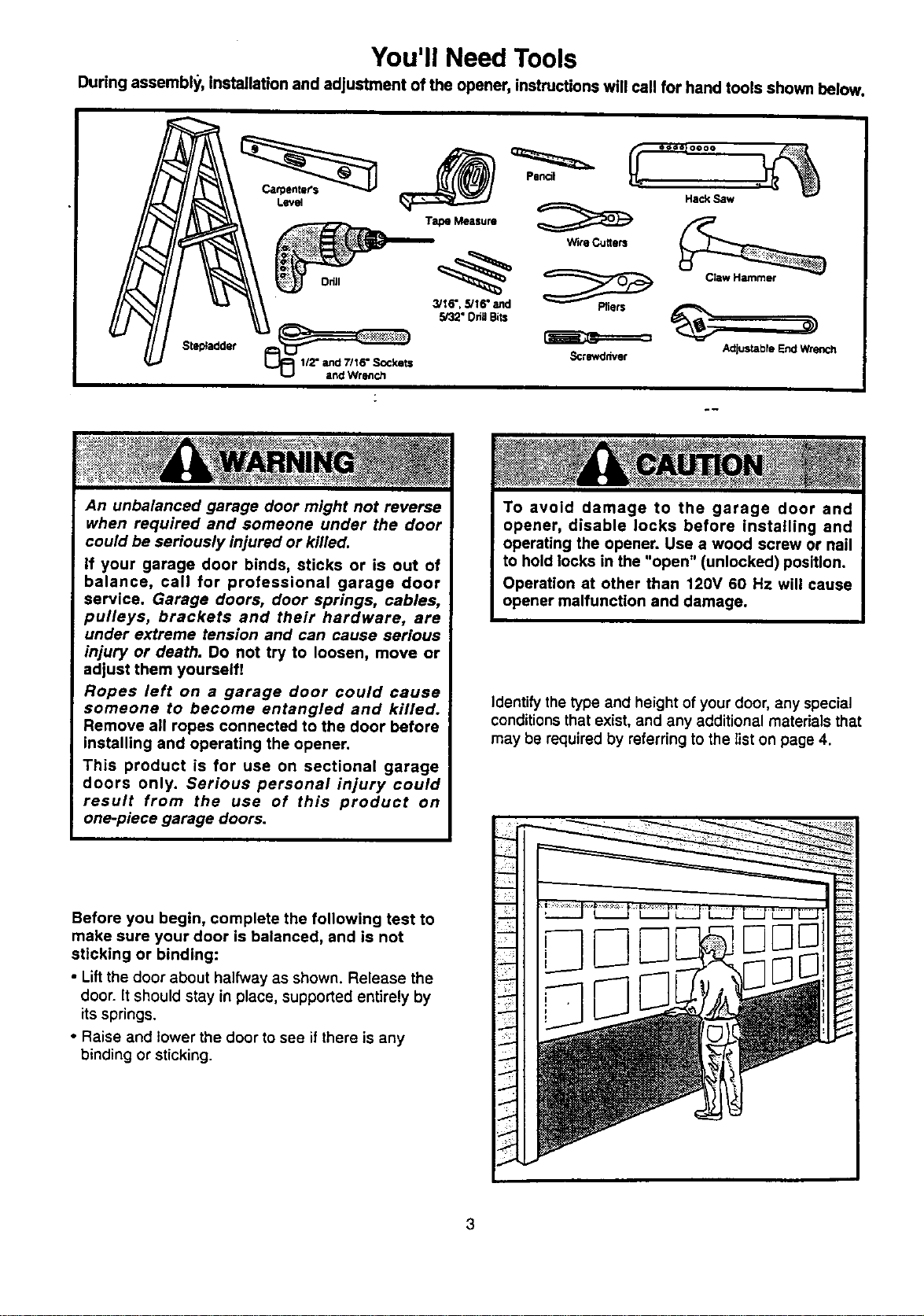
You'll Need Tools
During assembly, installation and adjustment of the opener, instructions will call for hand tools shown below.
Sts_adder
Level
Tape Measure _ Hack Saw
WireCutters
3/16", 5/16" and Pliers
5/32" Oda Bits
Sctewddvet
Claw Hammer
Adjus_bfe End Wrench
An unbalanced garage door might not reverse
when required and someone under the door
could be seriously injured or killed.
If your garage door binds, sticks or is out of
balance, call for professional garage door
service. Garage doors, door springs, cables,
pulleys, brackets and their hardware, are
under extreme tension and can cause serious
injury or death. Do not try to loosen, move or
adjust them yourself!
Ropes left on a garage door could cause
someone to become entangled and killed.
Remove all ropes connected to the door before
installing and operating the opener.
This product is for use on sectional garage
doors only. Serious personal injury could
result from the use of this product on
one-piece garage doors.
Identify the type and height of your door, any special
conditionsthat exist, and any additional materials that
may be required by referring to the list on page 4.
Before you begin, complete the following test to
make sure your door is balanced, and is not
sticking or binding:
• Lift the door about halfway as shown. Release the
door. It should stay in place, supported entirely by
its springs.
• Raise and lower the door to see if there is any
binding or sticking.
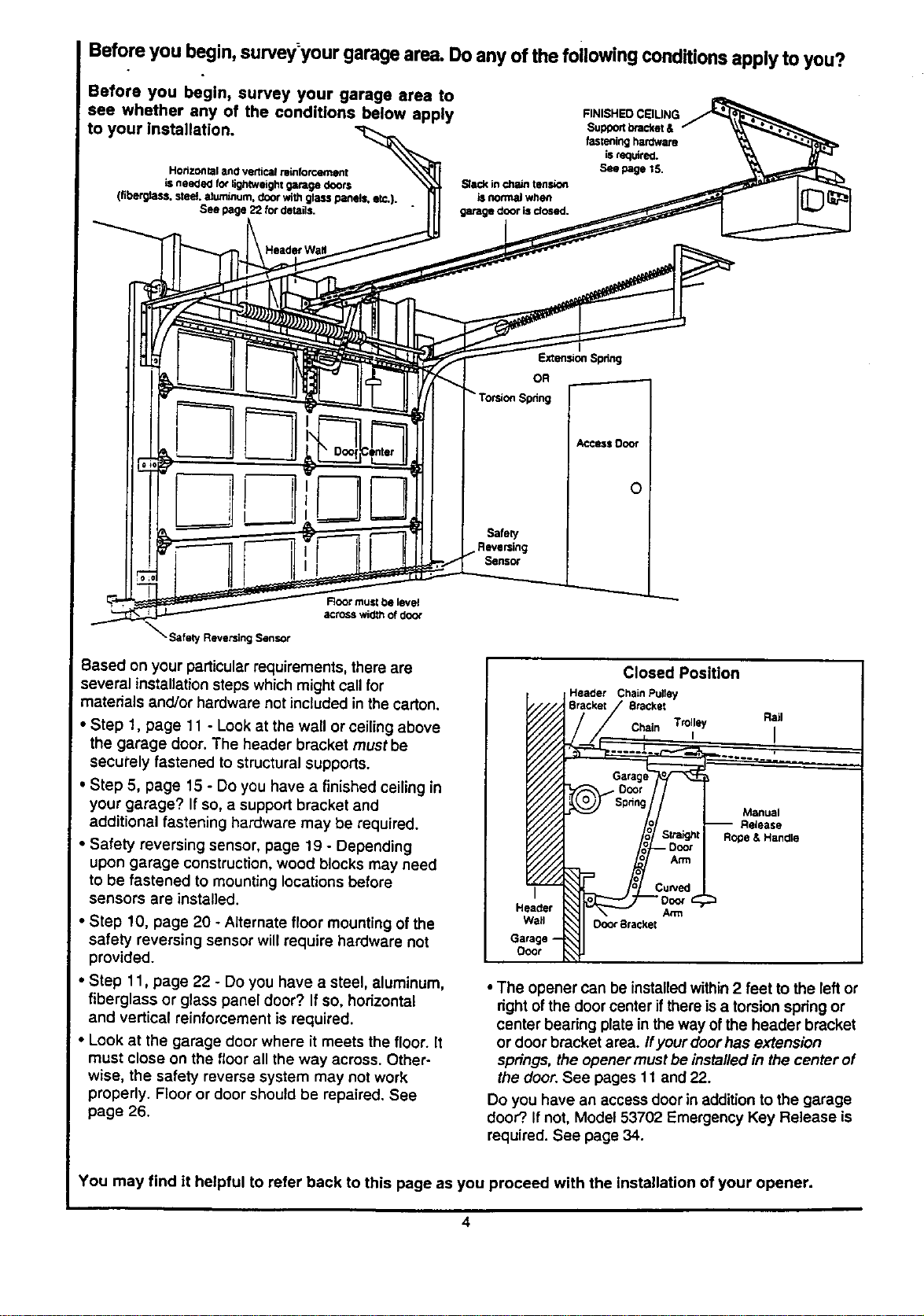
Before you begin, survey:yourgarage area.Do any of the following COnditionsapply to you?
Before you begin, survey your garage area to
see whether any of the conditions below apply
to your installation.
HorizoNtaland vertic_ reinfofr.,ernent
isneeded fo_ligh_veightgaragedoors
(flberg_tss.steel aluminum,door wireglasspanels,etc,).
See page22 fordetails.
SI_ in chain tension
is nermal when
garage door is dosed.
FINISHEDCSIUNG
Supportbracket&
fasteninghardware
Lsrequired.
See page 15.
Header Wa#
Extension Spdng
OR
Torsion Spdng
_ccsss Door
Safety
Sens_
Root must be level
across wid_ of doo_
• Safety Reversing Sensor
Based on your particular requirements, there are
several installationsteps which mightcall for
materials and/or hardware not included in the carton.
• Step t, page 11 - Look at the wall or ceiling above
the garage door. The header bracket must be
securely fastened to structural supports.
• Step 5, page 15 - Do you have a finished ceiling in
your garage? If so, a support bracket and
additional fastening hardware may be required.
• Safety reversing sensor, page 19 - Depending
upon garage construction, wood blocks may need
to be fastened to mounting locations before
sensors are installed.
• Step 10, page 20 - Alternate floor mounting ofthe
safety reversing sensor will require hardware not
provided.
• Step 11, page 22 - Do you have a steel, aluminum,
fiberglass or glass panel door? If so, horizontal
and vertical reinforcement is required.
• Look at the garage door where it meets the floor. It
must close on the floor all the way across. Other-
wise, the safety reverse system may not work
properly. Floor or door should be repaired. See
page 26.
I
Closed Position
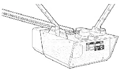
Header Chain Pulley
Stacker
Chain Trolley Rail
, I
Manual
Release
Arm
Door 8racket
Garage
ODOr
• The opener can be installedwithin2 feet to the left or
right ofthe door center ifthere is a torsionspring or
center bearing plate in the way ofthe header bracket
or door bracket area. Ifyour doorhas extension
springs, the opener mustbe installed in the center of
the door.See pages 1t and 22.
Do you have an access door in addition to the garage
door?.If not, Model 53702 Emergency Key Release is
required. See page 34.
You may find it helpful to refer back to this page as you proceed with the installation of your opener.
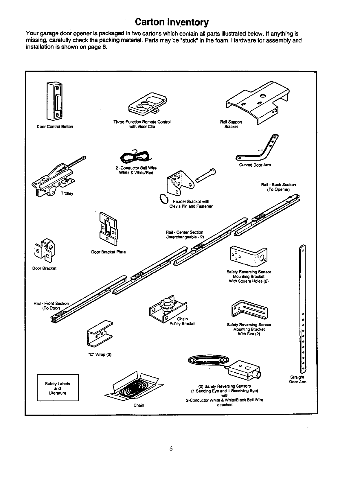
Carton Inventory
Your garage door opener is packaged in two cartons which contain all parts illustrated below. If anything is
missing, carefully check the pecking material. Parts may be "stuck"in the foam. Hardware for assembly and
installation is shown on page 6.
Tilme-Functk_ RemoteControl RailSupport
Door ControlButton withV'_O_Clip Br_c_,et
@
Door Bracket
Ttotiey
Rail- FrontSection
(To Ooo0
Safely Labels
and
Literature
Door Bracket Plate
Rail- Center Section
(Interci_angeable.2)
Curved DoorAnn
RailoBackSection
(To Opener)
Safety Reversing Sensor
Mounting Bracket
With Square Holes (2)
I
"C"Wrap (2)
Chain
_cket
Chain
SafetyReversingSensor
MountingBracket
WithStot(2)
(2) Safety Reversing Sensors
(1 Sending Eye and 1 Receiving Eye)
_th
2-C_lductor White & White/Black Bell Wire
attached
5
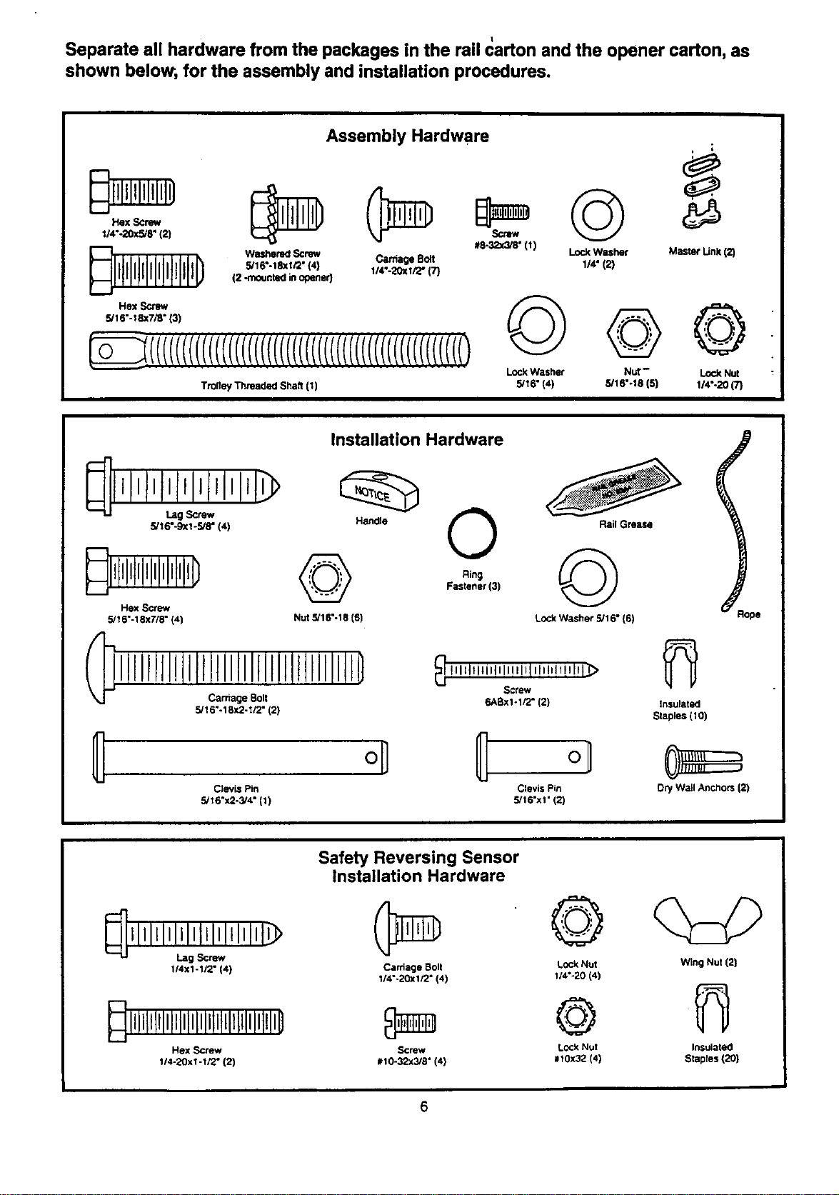
Separate all hardware from the packages in the rail carton and the opener carton, as
shown below, for the assembly and installation procedures.
Assembly Hardware
Hex Screw
1/4".20xS/r (2)
_lll@illIPIlll0
Hex Screw
5/16"-18x7/8" (3)
#8-32x_8" (1)
Lock Washer
Washemd Screw Caffiage Bolt 1/4" (2}
5/16".18xi/2" {4) 1/4".20xi/2" (7)
(2 -mounted in opener}
TrolleyThreadedshaft{1)
©
Lock Washer
5/16" (4)
©
Nut-
5/16"-18(5)
i
Master Link(2)
©
Lock Nut
1/4"-20 (7)
Installation Hardware
5/16"-9Xl -5/8" (4)
Handle
_ll!llllllllllllltll0
Hex Screw
5/16"-18x7/8" (4) Nut 5116"-18 (6)
Carnage Bolt
III[ll!iIIIIIIIIitlltllllillD
5/16"-18X2-I/2" 12)
0
Ring
Fastaner(3)
Rail Grease
©
Lock WaSher 5/16" (6)
_ i tqlllil,_lllilflllIIIl_
Screw
6ABxl-1/2" (2)
Clevis Pin Clevis Pin
5/16"x2-3/4" (1) 5/16"x1" (2)
Insulated
Staples (10)
Dry W_dlAnchors (2)
_llll=llllllltllllllllt_
Lag Screw
114x1-1/2" (4)
Dllll!liilllililililillillliilillli0
Hex screw
114-20xi-1/2" (2)
Safety Reversing Sensor
Installation Hardware
Carriage Boll
1/4"-20xlr2" (4)
Screw
#I0-32x318" (41
©
Lock Nut
1/4"-20 (4)
©
Lock NUt
#I0X32 (4)
Wing Nut (2)
Insulated
Staples (20)
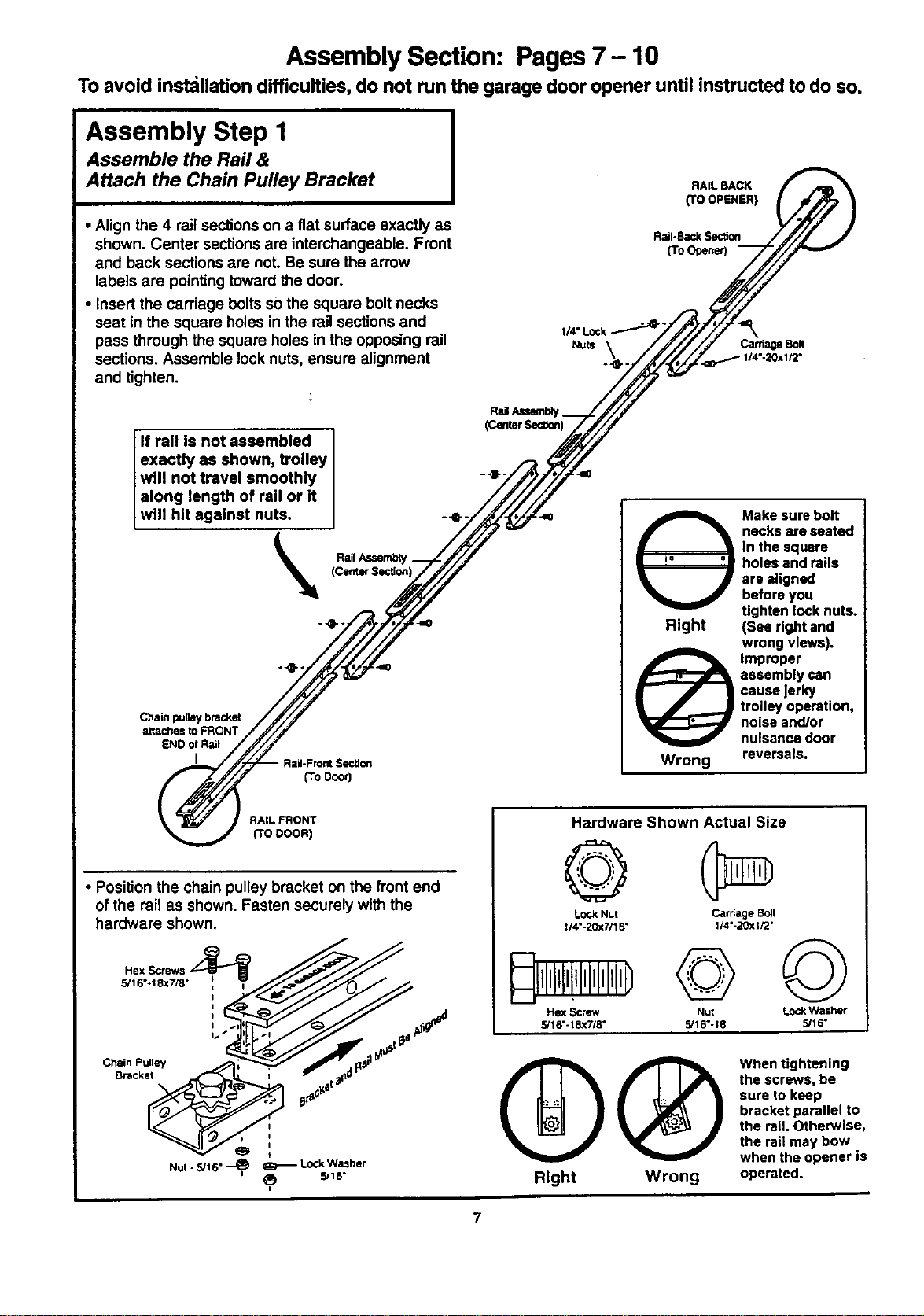
Assembly Section: Pages7- 10
To avoid installation difficulties, do not run the garage door opener until instructed to do so.
Assembly Step I
Assemble the Rail &
Attach the Chain Pulley Bracket
• Align the 4 rail sections on a fiat surface exactly as
shown. Center sections are interchangeable. Front
and back sections are not. Be sure the arrow
labels are pointingtoward the door.
• Insert the carriage bolts so the square bolt necks
seat in the square holes in the rail sections and
pass through the square holes in the opposing rail
sections. Assemble lock nuts, ensure alignment
and tighten.
RAIL BACK
(TO OPENER)
Rail-BackSection
(To Opener)
=,
CarriageBolt
I14"-20x I/2"
(CenterS_-"aon)
If rail is not assembled
exactly as shown, trolley
will not travel smoothly I -_
along length of rail or it
wi I hit against nuts. ] --e-. ,=
_l_ RailA,_
Chain pugey bracket
attachestoFRONT
END of Rail
I
[ToDoor]
i_ ake sure bolt
necks are seated
in the square
= _= =u holes and rails
are aligned
before you
tighten lock nuts.
Right (See right and
wrong views).
@ Improper
assembly can
cause jerky
trolley operation,
noise and/or
nuisance door
Wrong reversals.
RAIL FRONT
(TO DOOR)
• Position the chain pulley bracket on the front end
of the rail as shown. Fasten securely with the
hardware shown.
5/16*.18x7/8 •
Chain Pulley
Bracket
I
0
Nul - 5/16" _ _ Lock Washer
i_ 5/16"
Hardware Shown Actual Size
©
Lock Nut Carriage sclt
1/4"-20x7116" 1/4"-20xi/2"
Hex Screw Nut Lock Washer
5/16"-18xW8 ° 5/16"-18 5/16"
QQ
Right Wrong
When tightening
the screws, be
sure to keep
bracket parallel to
the rail. Otherwise,
the rail may bow
when the opener is
operated.
7
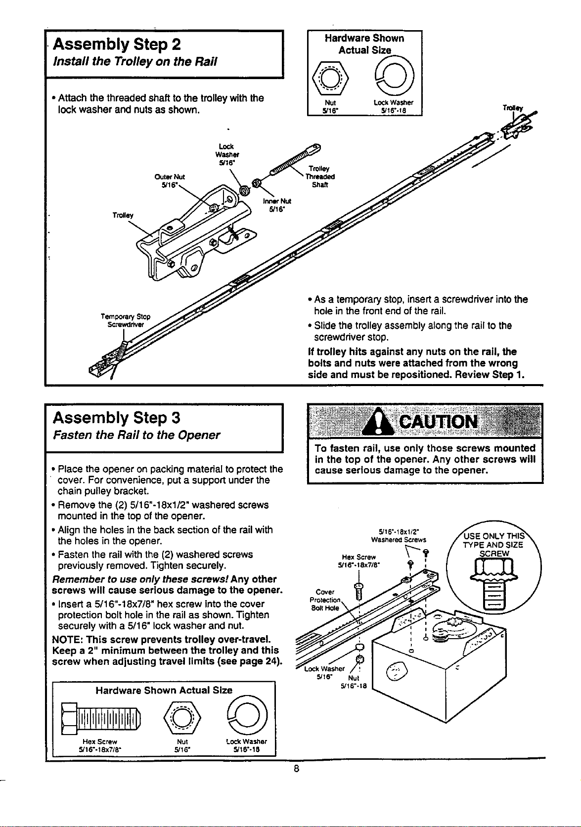
Assembly Step 2
Install the Trolley on the Rail
• Attach the threaded shaft to the trolley with the
lock washer and nuts as shown.
Hardware Shown
Actual Size
NUt LOCkWasher
5/16" S/t6"-18
Outer Nut
5/16"_
• As a temporary stop, insert a screwdriver into the
hole in the front end of the rail.
• Slide the trolley assembly along the rail to the
screwdriver stop.
If trolley hits against any nuts on the rail, the
bolts and nuts were attached from the wrong
side and must be repositioned. Review Step 1.
Assembly Step 3 I
Fasten the Rail to the Opener
I
• Place the opener on packing material to protect the
cover. For convenience, put a support under the
chain pulley bracket.
• Remove the (2) 5/16"-18x1/2" washered screws
mounted in the top of the opener.
• Align the holes in the back section of the rail with
the holes in the opener.
• Fasten the rail with the (2) washered screws
previously removed. Tighten securely.
Remember to use only these screws! Any other
screws will cause serious damage to the opener.
• Insert a 5/16"-18x7/8" hex screw into the cover
protection bolt hole in the rail as shown. Tighten
securely with a 5/16" lock washer and nut,
NOTE: This screw prevents trolley over-traveL
Keep a 2" minimum between the trolley and this
screw when adjusting travel limits (see page 24).
Hardware Shown Actual Size
I,t,III,I,I,I,I,I,IID
Hex Screw Nut Lock Washer
5/16"-18x718" 5/16" 5/16"-18
5116"-18x112"
Washered Screws
Hex Screw _ _
5/16°-t 8x7/8"
Covet
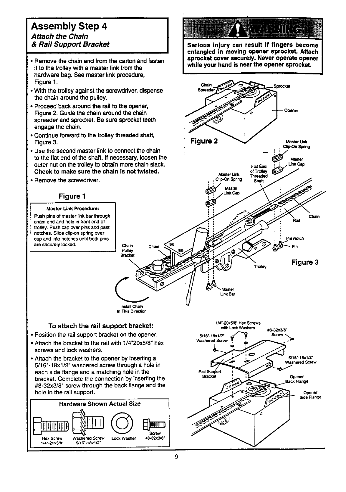
Assembly Step 4
Attach the Chain
& Rail Support Bracket
• Remove the chain end from the carton and fasten
it to the trolley with a master linkfrom the
hardware bag. See master link procedure,
Figure 1.
• With the trolley against the screwdriver, dispense
the chain around the pulley.
• Proceed back around the rail to the opener,
Figure 2. Guide the chain around the chain
spreader and sprocket. Be sure sprocket teeth
engage the chain.
• Continue forward to the trolley threaded shaft,
Figure 3.
• Use the second master link to connect the chain
to the flat end of the shaft. If necessary, loosen the
outer nut on the trolley to obtain more chain slack.
Check to make sure the chain is not twisted.
• Remove the screwdriver.
Figure I
Master Link Procedure:
Push pins of master link bar through
ct_ain end and hole in front end of
trolley. Push cap over pins and past
notches. Slide clip-on spdng over
cap and into notches until both pins
are securely locked.
Chain Chain
Pulley \
Bracket
Install Chain
In This Direction
To attach the rail support bracket:
• Position the railsupport bracket on the opener.
• Attach the bracket to the rail with 1/4"20x5/8" hex
screws and lock washers.
• Attach the bracket to the opener by inserting a
5/16"-18xl/2" washered screw through a hole in
each side flange and a matching hole in the
bracket. Complete the connection by inserting the
#8-32x3/8" screw through the back flange and the
hole in the rail support.
Hardware Shown Actual Size
Hex Screw Washered Screw Lock Washer #8-32x_'8"
1;4"-20XS/8" 5116"-18x112"
Chain_,%orodmt
" Figure 2 _ M_rUnk
,,/,,, ClkPC_Spdng
Master
Rat End
of Trolley
MLStef Unk Th,laded
Ctip-On Spdng Shaft
Master
Chain
Rail
Pin Notch
Tr=rsy Figure 3
Master
[Jnk Bar
114"-20x5/8"HsxScrews
with LOCkWasherS e8-32x3/8"
Bracket ; _ i V Ogener
Back Range
Opener
S_de Fisnge
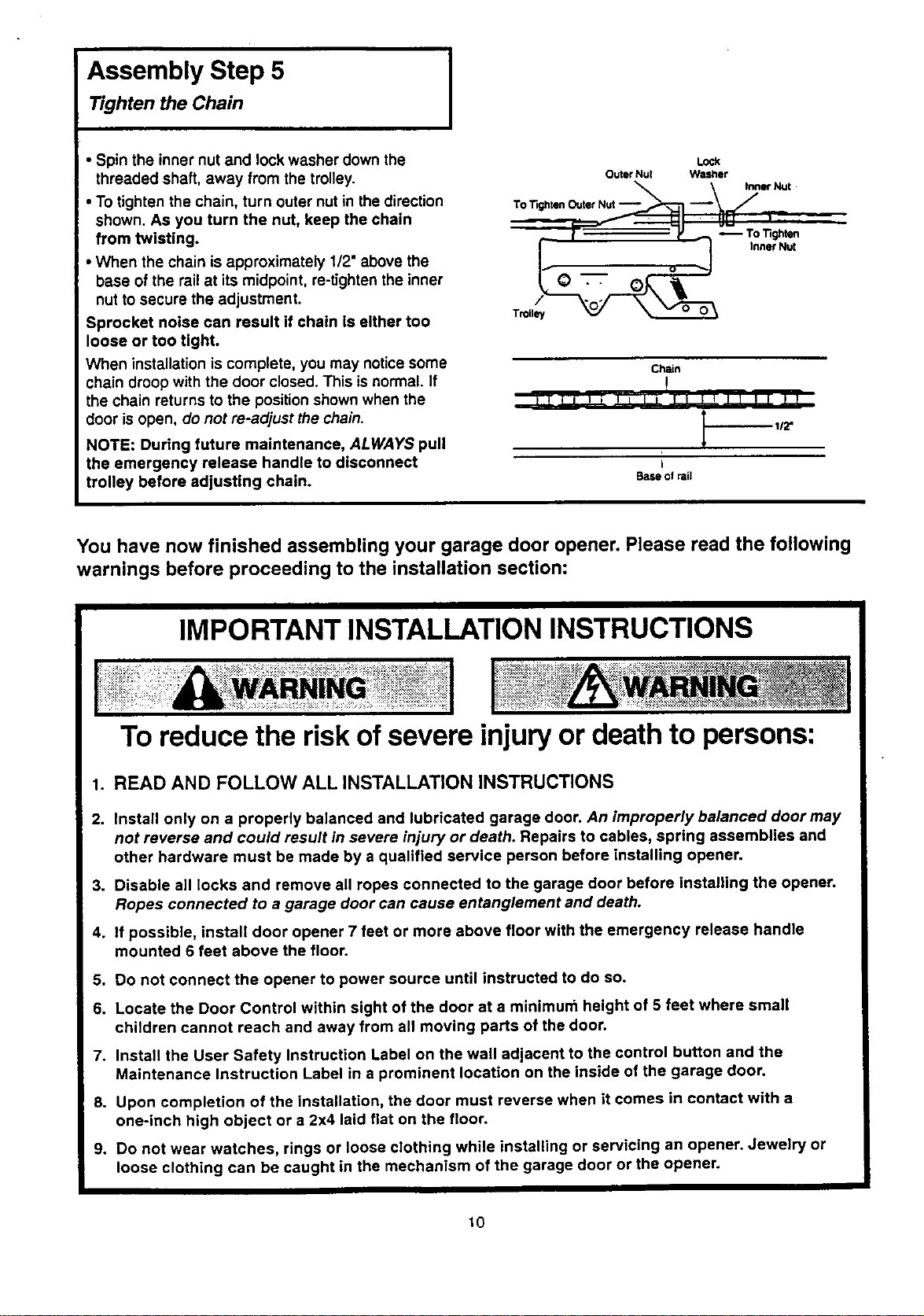
Assembly Step 5
Tighten the Chain
• Spin the inner nut and lock washer down the
threaded shaft, away from the trolley.
• To tighten the chain, turn outer nut in the direction
shown. As you turn the nut, keep the chain
from twisting.
• When the chain is approximately 1/2" above the
base of the rail at its midpoint, re-tighten the inner
nut to secure the adjustment.
Sprocket noise can result if chain Is either too
loose or too tight.
When installation is complete, you may notice some
chain droop with the door closed. This isnormal. If
the chain returns to the position shown when the
door is open. do not re-adjust the chain.
NOTE: During future maintenance, ALWAYS pull
the emergency release handle to disconnect
trolley before adjusting chain.
Lock
Outer Nut Wastler
To TightenOuterNut--_--_ --_ _,_ "Nu'
v -- ,:
i Q _ Inner NU[
Troil_
Chain
!
tJll _ _p l! 111'f! lr r r
Base of rail
You have now finished assembling your garage door opener. Please read the following
warnings before proceeding to the installation section:
IMPORTANT INSTALLATION INSTRUCTIONS
To reduce the risk ofsevere injuryor death to persons:
1. READ AND FOLLOW ALL INSTALLATION INSTRUCTIONS
2. install only on a properly balanced and lubricated garage door. An improperly balanced door may
not reverse and could result in severe injury or death. Repairs to cables, spring assemblies and
other hardware must be made by a qualified service person before installing opener.
3. Disable all locks and remove all ropes connected to the garage door before installing the opener.
Ropes connected to a garage door can cause entanglement and death.
4. if possible, install door opener 7 feet or more above floor with the emergency release handle
mounted 6 feet above the floor.
5. Do not connect the opener to power source until instructed to do so.
6. Locate the Door Control within sight of the door at a minimurn height of 5 feet where small
children cannot reach and away from all moving parts of the door.
7. Install the User Safety Instruction Label on the wall adjacent to the control button and the
Maintenance Instruction Label in a prominent location on the inside of the garage door.
8. Upon completion of the installation, the door must reverse when it comes in contact with a
one-inch high object or a 2x4 laid flat on the floor.
9. Do not wear watches, rings or loose clothing while installing or servicing an opener. Jewelry or
loose clothing can be caught in the mechanism of the garage door or the opener.
10
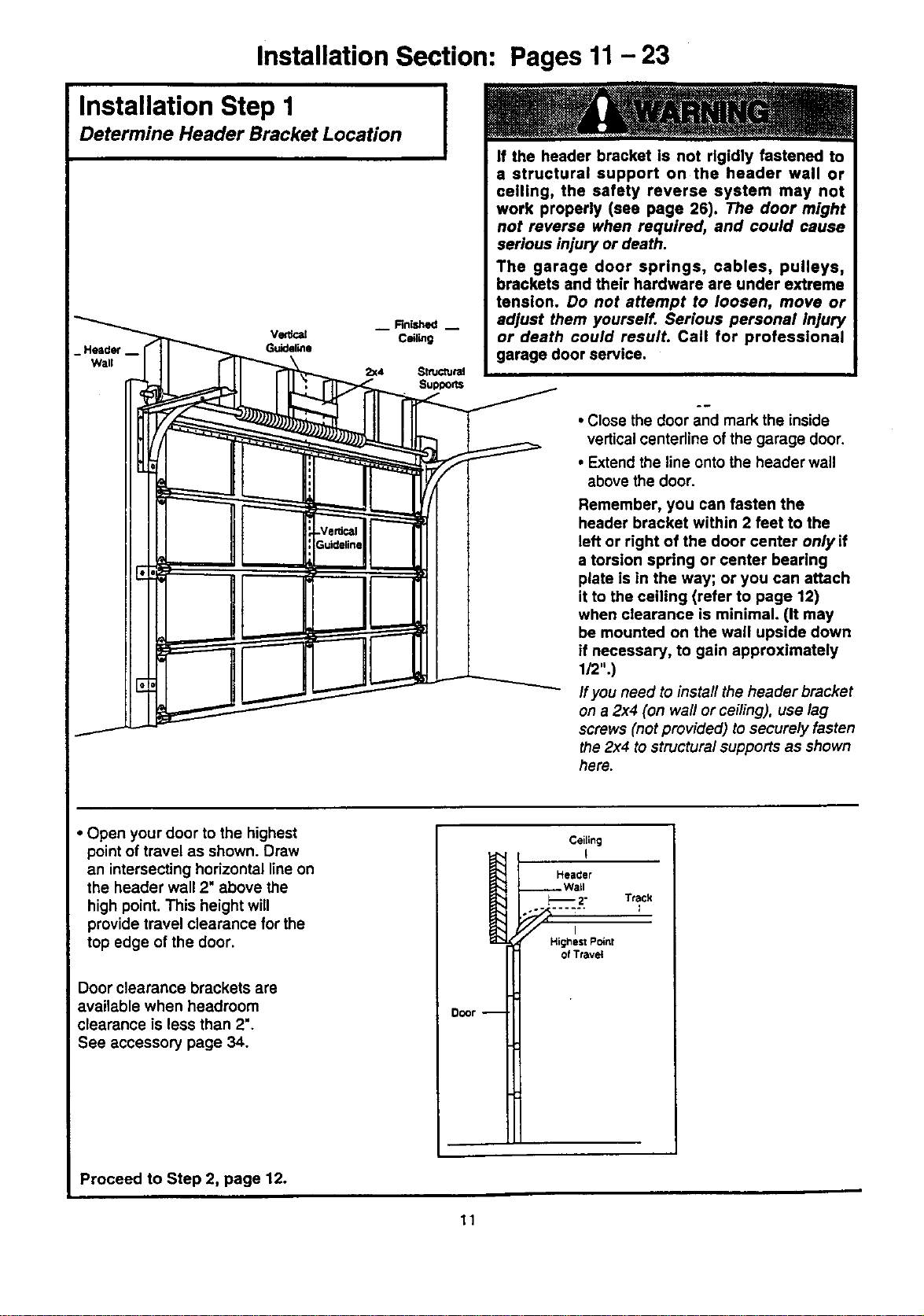
Installation Section: Pages 11- 23
Installation Step 1
Determine Header Bracket Location
I
__ Finished m
VG_Cal Ceiling
Guideline
2=(4 SmJCtUrel
Supports
If the header bracket is not rigidly fastened to
a structural support on the header wall or
ceiling, the safety reverse system may not
work properly (see page 26). The door might
not reverse when required, and could cause
serious injury or death.
The garage door springs, cables, pulleys,
brackets and their hardware are under extreme
tension. Do not attempt to loosen, move or
adjust them yourself. Serious personal injury
or death could resulL Call for professional
garage door service.
• Close the door and mark the inside
vertical centerline of the garage door.
• Extend the line onto the header wall
above the door.
Remember, you can fasten the
header bracket within 2 feet to the
left or right of the door center only if
a torsion spring or center bearing
plate is in the way; or you can attach
it to the ceiling (refer to page 12)
when clearance is minimal. (It may
be mounted on the wall upside down
if necessary, to gain approximately
1/2".)
If you need to install the header bracket
on a 2x4 (on wall or ceiling), use lag
screws (not provided) to securely fasten
the 2x4 to structuralsupports as shown
here.
• Open your door to the highest
point of travel as shown. Draw
an intersecting horizontal line on
the header wall 2" above the
high point. This height will
provide travel clearance for the
top edge of the door.
Door clearance brackets are
available when headroom
clearance is less than 2".
See accessory page 34.
Ceiling
I '
Heacler
__ Wall
2" Track
,- .... --" I
Higrtesl Point
of Travel
Door --
Proceed to Step 2, page 12.
11
Installation Step 2 I
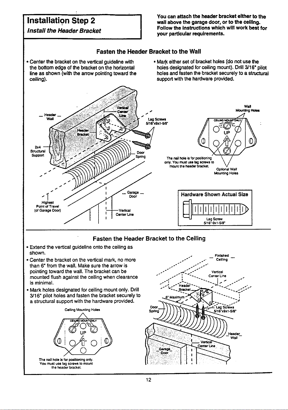
Install the Header Bracket
You can attach the header bracket either to the
wall above the garage door, or to the ceiling.
Follow the instructions which will work beet for
your particular requirements.
Fasten the Header Bracket to the Wall
• Center the bracket on the vertical guideline with
the bottom edge of the bracket on the horizontal
line as shown (with the arrow pointingtoward the
ceiling).
• Ma_ either set of bracket holes (do not use the
holes designated for ceiling mount). Drill 3/16" pilot
holes and fasten the bracket securely to a structural
supportwith the hardware provided.
2x4
Structural
Suptoott
j,
,J
4,
" I Door
Highest
Point of Travel
(ofGarage Ooor)
CenterLine
Wall
Moun_n__es
"2,
t f
Spdng The nail hole is for positioning
Optional Wall
Mounting Holes
Hardware Shown Actual Size
5/16"-9xl -5/8"
Fasten the Header Bracket to the Ceiling
• Extend the vertical guideline onto the ceiling as
shown.
• Center the bracket on the vertical mark, no more
than 6" from the wall. Make sure the arrow is
pointing toward the wall. The bracket can be
mounted flush against the ceilingwhen clearance
is minimal.
• Mark holes designated for ceiling mount only. Drill
3/16" pilot holes and fasten the bracket securely to
a structural support with the hardware provided.
Ceiling Mounting Holes
/',,
CE MOU_I_ I_Y
/
The hall hole is f_" positioning only.
YOU must use lag screws to mount
the heaclet bracket.
Header
wall
12
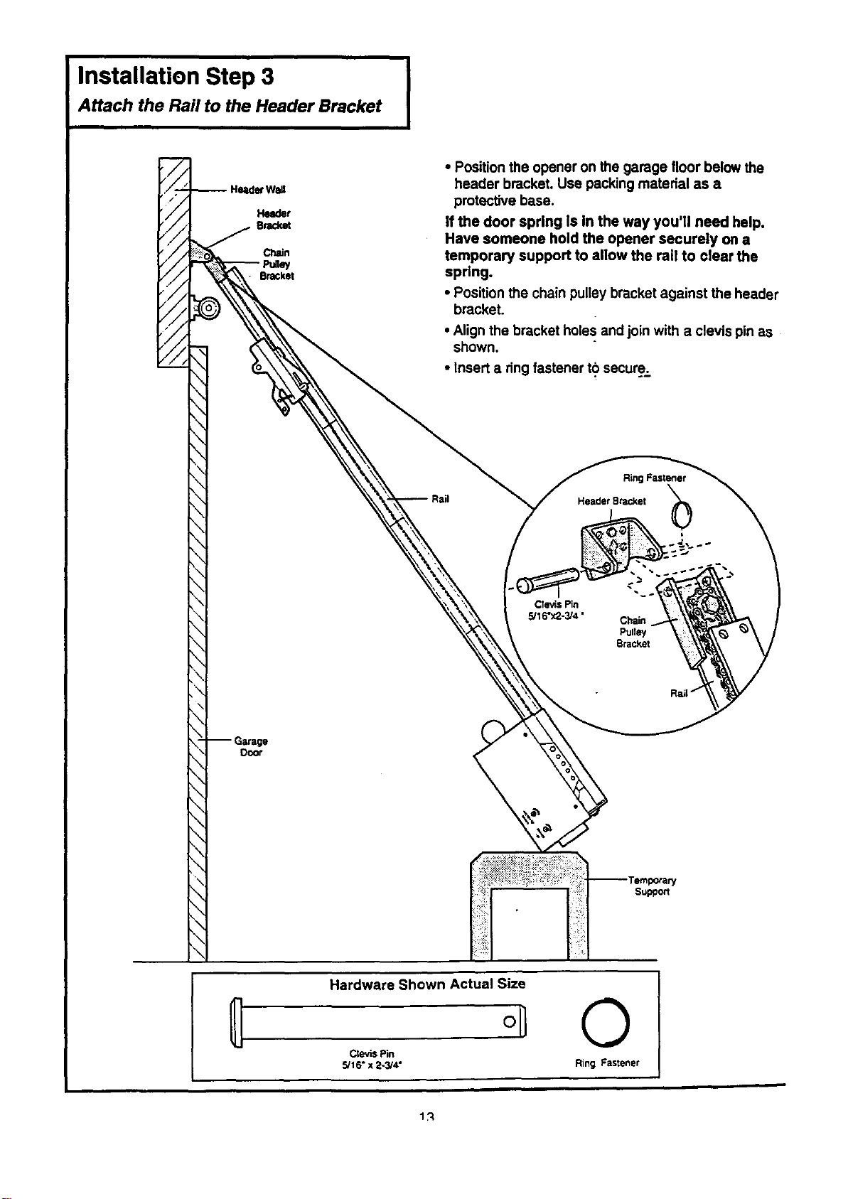
Installation Step 3 I
Attach the Rail to the Header Bracket
• Position the opener on the garage floor below the
header bracket. Use packing material as a
protective base.
If the door spring Is In the way you'll need help.
Have someone hold the opener securely on a
temporary support to allow the rail to clear the
spring.
• Position the chain pulley bracket against the header
bracket.
• Align the bracket holes and join with a clevis pin as
shown.
• Insert a ring fastener to secure.
Ring Fastener
HeaderBracket
O00f
Hardware Shown Actual Size
°11
Cte'_s Pin
5/16" x 2-3/4"
©
Ring Fastener
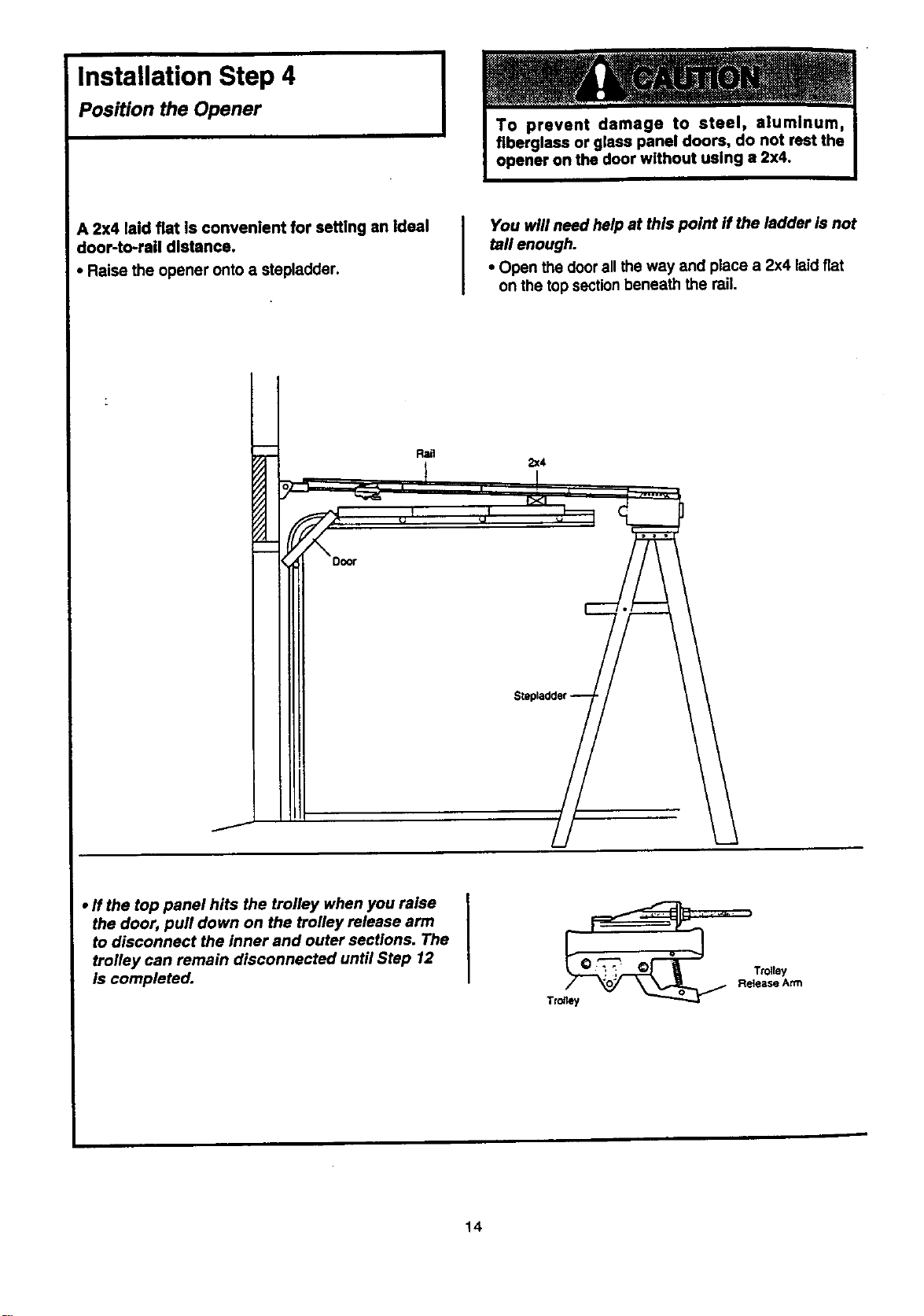
Installation Step 4
Position the Opener
I
A 2x4 laid fiat is convenient for setting an ideal
door-to-rail distance.
• Raise the opener onto a stepladder.
You will need help at this point if the ladder is not
tall enough.
• Open the door all the way and place a 2x4 laidfiat
on the top sectionbeneath the rail.
Rail
2x4
• ff the top panel hits the trolley when you raise
the door, pull down on the trolley release arm
to disconnect the inner and outer sections. The
trolley can remain disconnected until Step 12
is completed.
14
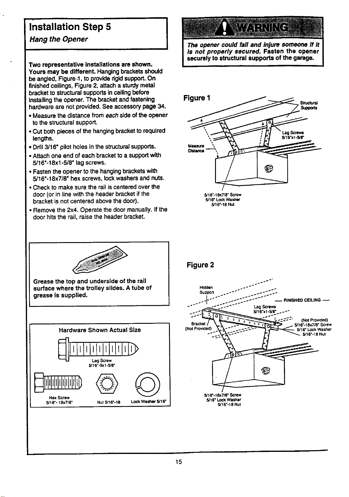
Installation Step 5
Hang the Opener
Two representative installations are shown.
Yours may be different. Hanging brackets should
be angled, Figure -1, to provide rigidsupport. On
finished ceilings, Figure 2, attach a sturdy metal
bracket to structural supports in ceiling before
installing the opener. The bracket and fastening
hardware are not provided. See accessory page 34.
• Measure the distance from each side of the opener
to the structural support.
• Cut both pieces of the hanging bracket to required
lengths.
• Drill 3/16" pilot holes in the structural supports.
• Attach one end of each bracket to a supportwith
5/16"-18xl-5/8" lag screws.
• Fasten the opener to the hanging brackets with
5/16"-18x7/8" hex screws, lock washers and nuts.
• Check to make sure the rail is centered over the
door (or in line with the header bracket ifthe
bracket is not centered above the door).
• Remove the 2x4. Operate the door manually. If the
door hits the rail, raise the header bracket.
Grease the top and underside of the rail
surface where the trolley slides. A tube of
grease is supplied.
Hardware Shown Actual Size
5/1 6"-9x1-5/8"
Hex Screw
5/16"- 18x7/8"
©©
Nut 5/16"- 18 LOCI<Washer 5/1 6"
Figure I
5/16"-18x7/8" S_ew
5/16" Lock Washer
5/16"-18 Nut
Figure 2
(Not Provided)
Bracket 5/16"-18x7/8" Screw
(Not Provided) _"Lock Wast;er
"'_ 5/16%18 Nut
5/16".tSx718" Screw
5/16" Lock Washer
5/16"-18 Nut
15
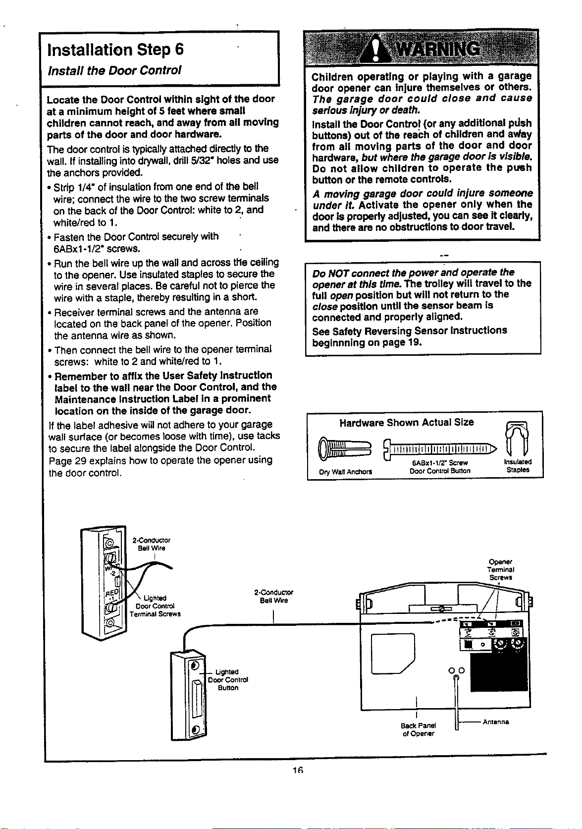
Installation Step 6
Install the Door Control I
Locate the Door Control within sight of the door
at a minimum height of 5 feet where small
children cannot reach, and away from all moving
parts of the door and door hardware.
The door control is typically attached directly to the
wall. If installinginto drywall,drill5/32" holes and use
the anchors provided.
• Stdp 1/4" of insulationfrom one end of the bell
wire; connect the wire to the two screw terminals
on the back of the Door Control: white to 2, and
white/red to 1.
• Fasten the Door Control securely with
6ABx1-1/2" screws.
• Run the bell wire up the wall and across the ceiling
to the opener. Use insulated staples to secure the
wire in several places. Be careful not to pieme the
wire with a staple, thereby resulting in a short.
• Receiver terminal screws and the antenna are
located on the back panel of the opener. Position
the antenna wire as shown.
• Then connect the bell wire to the opener terminal
screws: white to 2 and white/red to 1.
Remember to affix the User Safety instruction
label to the wall near the Door Control, and the
Maintenance Instruction Label in a prominent
location on the inside of the garage door.
f the label adhesive will not adhere to your garage
wall surface (or becomes loose with time), use tacks
to secure the label alongside the Door Control.
Page 29 explains how to operate the opener using
the door control.
Children operating or playing with a garage
door opener can injure themselves or others.
The garage door could close and cause
serious injury or death.
Install the Door Contro! (or any additional pdsh
buttons) out of the reach of children and av/ay
from all moving parts of the door and door
hardware, but where the garage door Is visible.
Do not allow children to operate the ptmh
button or the remote controls.
A moving garage door could injure someone
under it. Activate the opener only when the
door is properly adjusted, you can see it clearly,
and there are no obstructions to door travel.
Do NOT connect the power and operate the
opener at this time. The trolley will travel to the
full open position but will not return to the
close position until the sensor beam is
connected and properly aligned.
See Safety Reversing Sensor Instructions
beginnning on page 19.
I Hardwareih°wn Actual Size _
illlillstrlnlni_tllnUUinl_ll! _
6ABx1-1/2" Screw Insulated
Ocy W=tllAnchors Door Control Burton Staples
j
2-Concluctor
Be!l Wire
I
2-Conductor
Bell Wire
Door Contn_
Terminal Screws I
- I..Jghted
Ooo¢ Control
Burton
Opener
Terminal
Screws
Back Panel
o! Opener
1R
Installation Step 7
Install the Light
I
• Install a 75 watt maximum light bulb in the socket.
The light will rum ON and remain lit for
approximately 4-1/2 minutes when power is
connected. Then the lightwill rum OFF.
• If the bulb bums out prematurely due to vibration,
replace with a standard neck "Garage Door
Opener =bulb.
75Walt Max._
Light Bulb
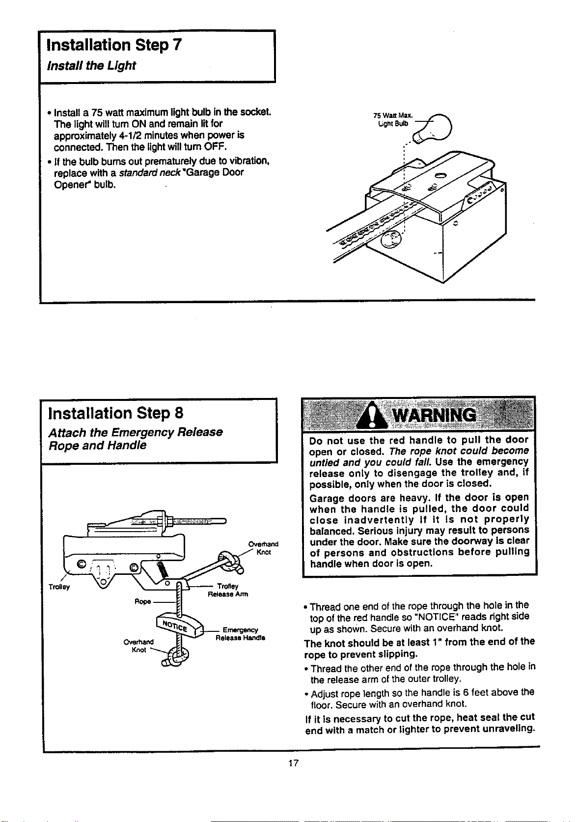
Installation Step 8
Attach the Emergency Release
Rope and Handle
Trolley
Overhand
Knol
Ove_nd
_:-_: : _>_;-,_,_::::s:,_::_ ,x_;,> ¸ ,_- _¥ _H ,:+_>:•
Do not use the red handle to pull the door
open or closed. The rope knot could become
untied and you could fall. Use the emergency
release only to disengage the trolley and, If
possible, only when the door is closed.
Garage doors are heavy. If the door is open
when the handle is pulled, the door could
close inadvertently if it is not properly
balanced. Serious injury may result to persons
under the door. Make sure the doorway is clear
of persons and obstructions before pulling
handle when door is open.
Release Arm
Release Handle
• Thread one end of the rope through the hole in the
top of the red handle so "NOTICE" reads right side
up as shown. Secure with an overhand knot.
The knot should be at least 1" from the end of the
rope to prevent slipping.
• Thread the other end of the rope through the hole in
the release arm of the outer trolley.
• Adjust rope length so the handle is 6 feet above the
floor. Secure with an overhand knot.
If it is necessary to cut the rope, heat seal the cut
end with a match or lighter to prevent unraveling.
17
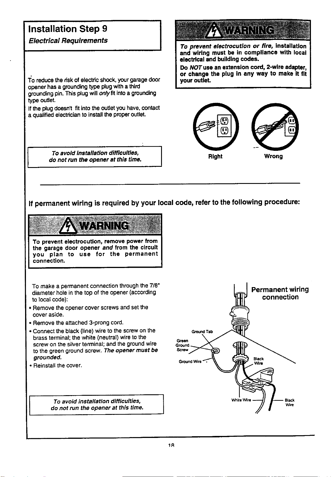
Installation Step 9
Electrical Requirements
I
1:o reduce the riskof electric shock, your garage door
opener has a grounding type plug with a third
grounding pin. This plug will onlyflt intoa grounding
type outlet.
If the plug doesn't fit intothe outlet you have, contact
a qualified electricianto installthe properoutlet.
I To avoid installation difficulties,
do not run the opener at this time.
Right Wrong
If permanent wiring is required by your local code, refer to the following procedure:
To make a permanent connection through the 718"
diameter hole in the top of the opener (according
to local code):
• Remove the opener cover screws and set the
cover aside.
• Remove the attached 3-prong cord.
• Connect the black (line) wire to the screw on the
brass terminal; the white (neutral) wire to the
screw on the silver terminal; and the ground wire
to the green ground screw. The opener must be
grounded.
• Reinstall the cover.
Ground Tab
Green
Ground
Screw
Permanent wiring
connection
Black
Wire
I To avoid installation difficulties,
do not run the opener at this time.
1R
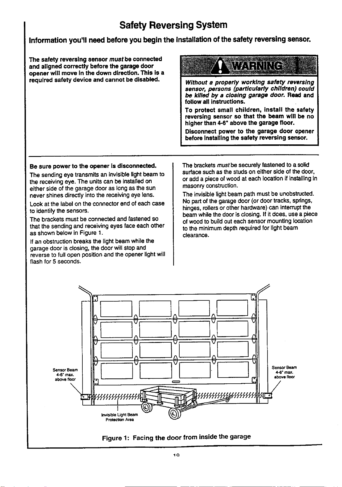
Safety Reversing System
Information you'll need before you begin the installation of the safety reversing sensor.
The safety reversing sensor must be connected
and aligned correctly before the garage door
opener will move in the down direction. This is a
required safety device and cannot be disabled.
Without a properly working safety reversing
sensor, persons (particularly children) could
be killed by a closing garage door. Read and
follow all instructions.
To protect small children, Install the safety
reversing sensor so that the beam will be no
higher than 4-6" above the garage floor.
Disconnect power to the garage door opener
before installing the safety reversing sensor.
Be sure power to the opener ls disconnected.
The sending eye transmits an invisible light beam to
the receiving eye. The unitscan be installedon
either side of the garage door as long as the sun
never shines directly into the receiving eye lens.
Look at the label on the connector end ofeach case
to identify the sensors.
The brackets must be connected and fastened so
that the sending and receiving eyes face each other
as shown below in Figure 1,
If an obstruction breaks the light beam while the
garage door is closing, the door will stop and
reverse to full open position and the opener light will
flash for 5 seconds.
The brackets mustbe securely fastened to a solid
surface such as the studs on either side of the door,
or add a piece of wood at each location if installingin
masonry construction.
The invisible lightbeam path must be unobstructed.
No part of the garage door (or door tracks, springs,
hinges, rollersor other hardware) can interruptthe
beam while the door is closing. If it does, use a piece
of wood to buildout each sensor mounting location
to the minimumdepth required for light beam
clearance.
Sensor Beam
4-6" max,
above floor
\
I
Invisible Light Beam
Protection Area
Sensor Beam
4-6" max.
above floor
Figure 1: Facing the door from inside the garage
_Q
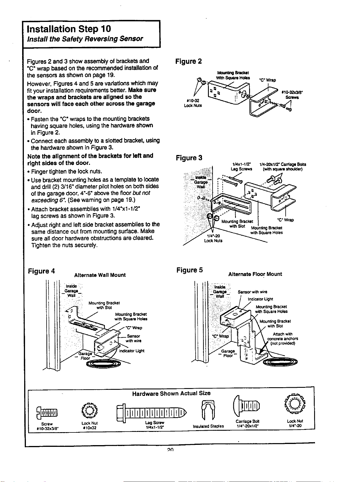
Installation Step 10 I
Install the Safety Reversing Sensor
I
Figures 2 and 3 show assembly of brackets and
"C" wrap based on the recommended installation of
the sensors as shown on page 19,
However, Figures 4 and 5 are variations which may
fit your installation requirements better. Make sure
the wraps and brackets are allgned so the
sensors will face each other across the garage
door.
• Fasten the "C" wraps tothe mounting brackets
having square holes, using the hardware shown
in Figure 2.
• Connect each assembly to a slotted bracket, using
the hardware shown in Figure 3.
Note the allgnment of the brackets for left and
right sides of the door.
• Finger tighten the lock nuts.
• Use bracket mounting holesas a template to locate
and drill(2) 3/16" diameter pilotholes on bothsides
of the garage door, 4"-6"above the f]corbut not
exceeding 6". (See warning on page 19.)
• Attach bracket assemblies with 1/4"x1-1/2"
lag screws as shown in Figure 3.
• Adjust right and left side bracket assemblies to the
same distance out from mounting surface. Make
sure all door hardware obstructionsare cleared.
Tighten the nuts securely.
Figure 2
MounUngenc_th
. With _ HOleS "C" Wrap
Figure 3
1/4X1-I/2° 114-20X1/2"Ca_lge
Lag Screws (with_are,shoulder)
i:z!.
I14"-20
LOCI(Nuts
"C"Wrap
Bracket
withSquareHoles
Figure 4
J
Alternate Wall Mount
-- Root-
Mounting Bracket
with Squa_ Holes
withwire
thdicatot Light
Figure 5
./
Alternate Floor Mount
iinside
-Wall
Sensor with wire
fndicator L[ght
J Moun_ng Bracket
Square Holes
, Mounting Bracket
! with Slot
Altac_ with
i ' €oncrete anchors
Hardware Shown Actual Size
© @
SCrew Lock Nut Lag Scrlw/ Carriage Boll LOCkNut
#10-32x3/8" #t0x32 1/4xl -1/2" Insulated Staples 1/4"-20xl/2" 114"-20
_n
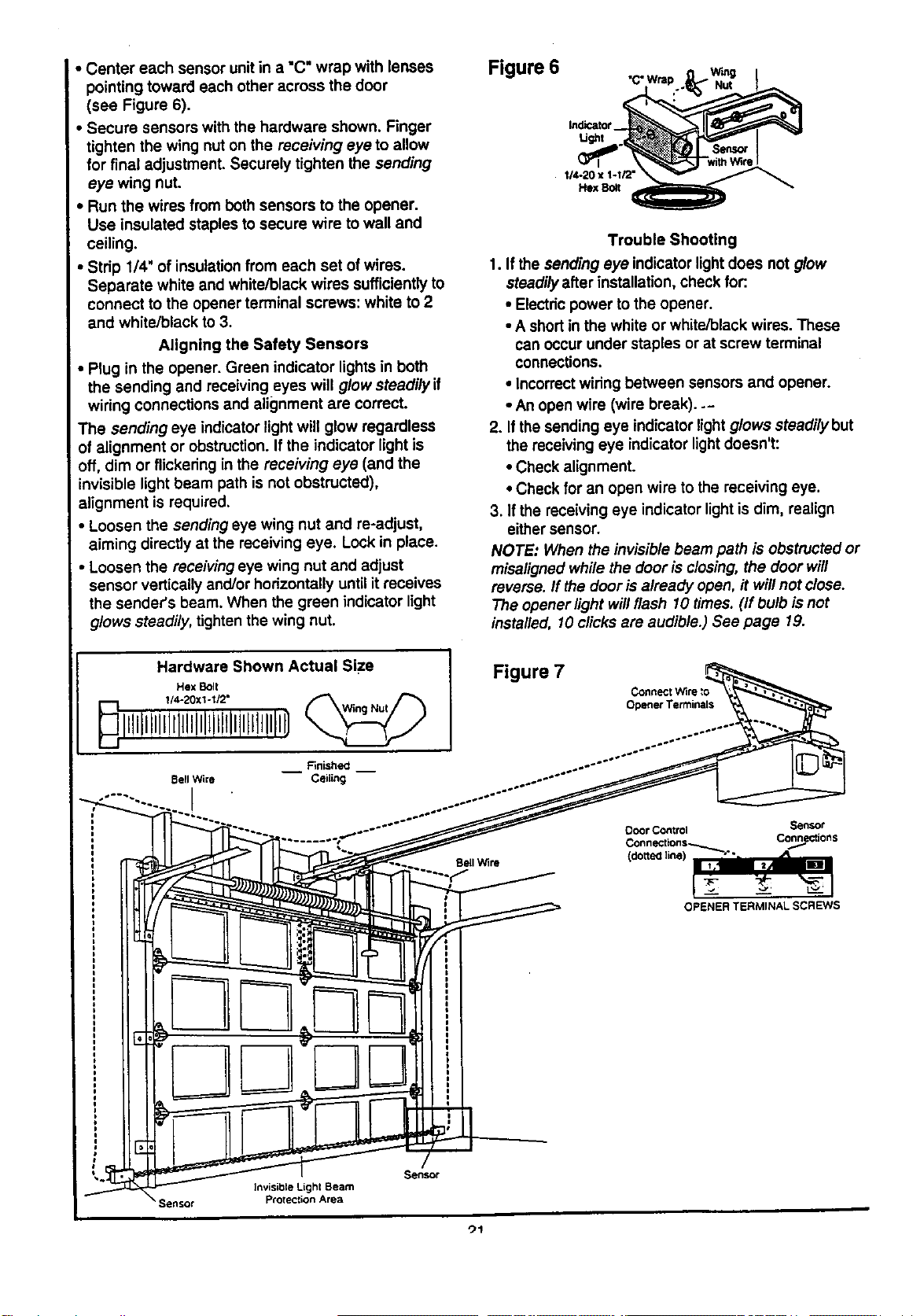
• Center each sensor unitin a "C" wrap with lenses
pointing toward each other across the door
(see Figure 6).
Secure sensors with the hardware shown. Finger
tighten the wing nut on the receiving eye to allow
for final adjustment. Securely tighten the sending
eye wing nut.
, Run the wires from both sensors to the opener.
Use insulated staples to secure wire to wall and
ceiling.
• Strip 1/4' of insulation from each set of wires.
Separate white and white/black wires sufficientlyto
connect to the opener terminal screws: white to 2
and white/black to 3.
Aligning the Safety Sensors
• Plug in the opener. Green indicator lightsin both
the sending and receiving eyes will glow steadily if
wiring connections and alignment are correct.
The sending eye indicator light will glow regardless
of alignment or obstruction. If the indicator light is
off, dim or flickering in the receiving eye (and the
invisible light beam path is not obstructed),
alignment is required.
• Loosen the sending eye wing nut and re-adjust,
aiming directly at the receiving eye. Lock in place.
• Loosen the receiving eye wing nut and adjust
sensor vertically and/or horizontally until it receives
the sender's beam. When the green indicator light
glows steadily, tighten the wing nut.
Figure 6
Indicator
Ugm
114-20 x 1-1/2"
Hex Bolt
Trouble Shooting
1. If the sending eye indicator light does not glow
steadilyafter installation, check for:.
• Electricpower to the opener.
• A short in the white or white/black wires. These
can occur under staples or at screw terminal
connections.
• Incorrectwiring between sensors and opener.
• An open wire (wire break)..-
2. If the sending eye indicator light glows steadilybut
the receiving eye indicator lightdoesn't:
• Check alignment.
• Check for an open wire to the receiving eye.
3. If the receiving eye indicator light is dim, realign
either sensor.
NOTE: When the invisible beam path is obstructed or
misaligned while the door is closing, the door will
reverse. If the door isalready open, it willnot close.
The opener light willflash 10 times. (if bulb is net
installed, 10 clicks are audible.) See page 19.
Hardware Shown Actual Size
Hex Bolt
Bell Wire
I
Figure 7
Connect Wire
Opener Terminals
Sensor
Connections
OPENER TERMINAL SCREWS
Sensor
Invisible Lighl Beam
Protection Area
")1
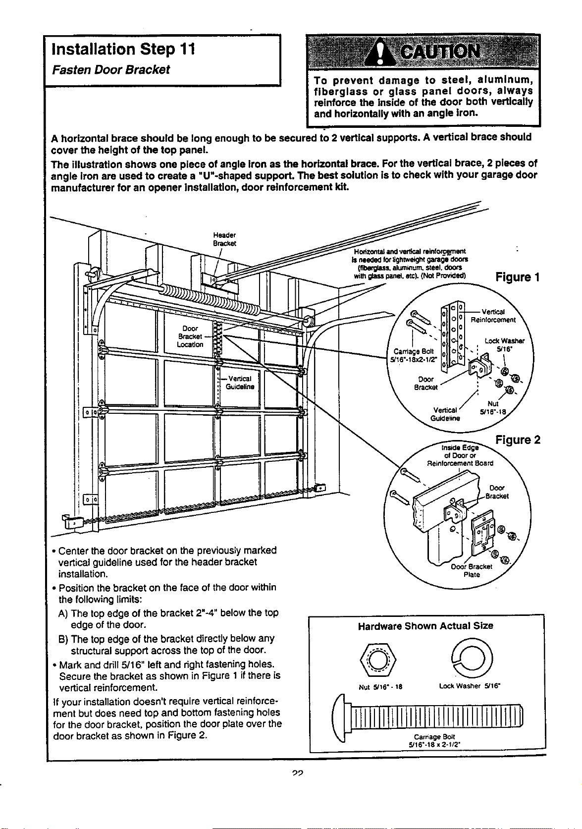
Installation Step 11 I
I
Fasten Door Bracket
A horizontal brace should be long enough to be secured to 2 vertical supports. A vertical brace should
cover the height of the top panel.
The illustration shows one piece of angle iron as the horizontal brace. For the vertical brace, 2 pieces of
angle iron are used to create a "U"-shaped support. The best solution is to check with your garage door
manufacturer for an opener installation, door reinforcement klL
Header
Bracket
Figure I
Door
Bracket-
Location
CardageBolt
5/t6"-18x2-t12"
Reinforcement
LockWasher
5/16"
F Nu_
Vertical 5/16%18
Guideline
Figure 2
of Dooror
ReinforcementBoard
• Center the door bracket on the previously marked
vertical guideline used for the header bracket
installation.
• Position the bracket on the face of the door within
the following limits:
A) The top edge of the bracket 2"-4" below the top
edge of the door.
B) The top edge of the bracket directly below any
structuralsupport across the top of the door.
• Mark and drill 5/16" left and right fastening holes.
Secure the bracket as shown in Figure 1 if there is
vertical reinforcement.
If your installation doesn't require vertical reinforce-
ment but does need top and bottom fastening holes
for the door bracket, position the door plate over the
door bracket as shown in Figure 2.
Plate
Hardware Shown Actual Size
©
Nut 5/16" - 18 LOCkWasher 5/16"
iLllllllLllllllillllllIlllilllllID
Ca_iage Bo_t
5/16"-18 x 2-1/2"
"29
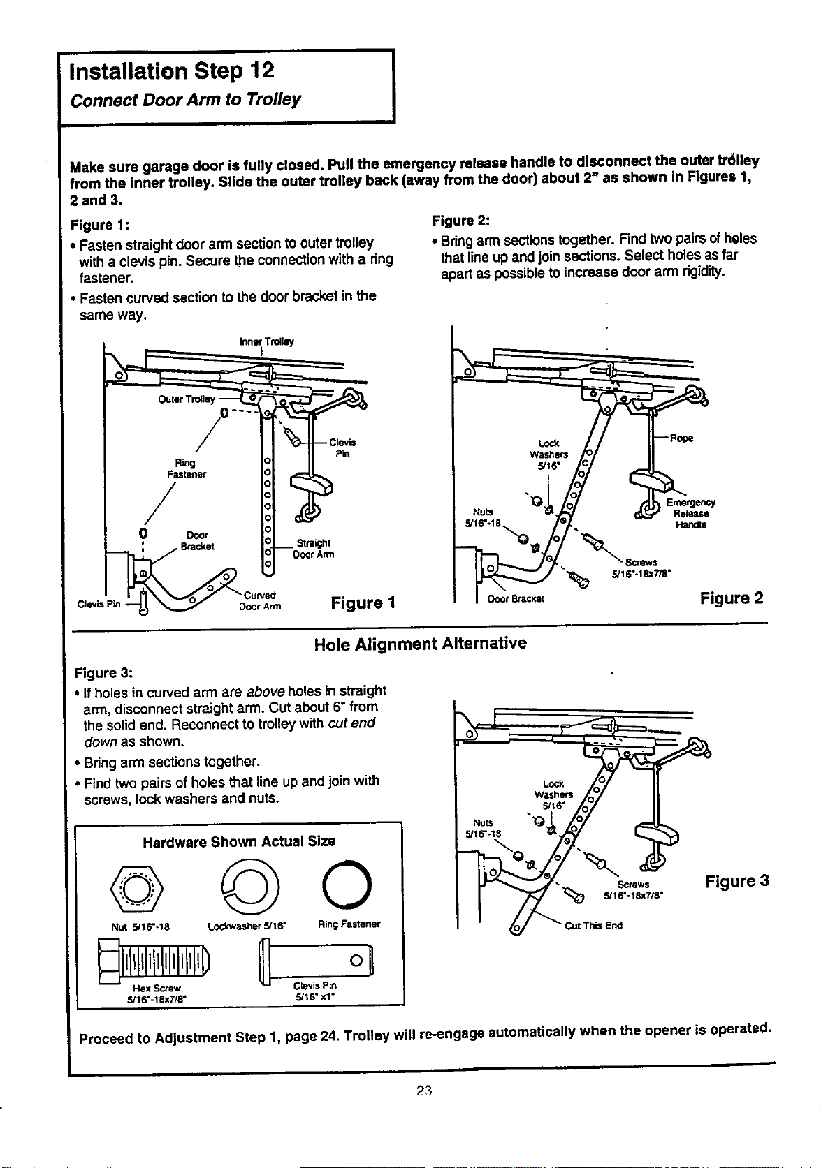
Installation Step 12
Connect Door Arm to Trolley
I
Make sure garage door is fully closed. Pull the emergency release handle to disconnect the outer fr611ey
from the inner trolley. Slide the outer trolley back (away from the door) about 2" as shown In Figures 1,
2 and 3.
Figure 1:
• Fasten straight door arm section to outer trolley
with a clevis pin Secure the connection with a ring
fastener
• Fasten curved section to the door bracket in the
Figure 2:
• Bringarm sections together Find two pairsof heles
that line up and join sections Select holes as far
apart as possible to increase door arm rigidity
same way.
w,__,_ // II-_°-
&If6,
_ .777%
5/,6,8.° p/ -- .,_o
Figure 2
Hole Alignment Alternative
Figure 3:
• If holes in curved arm are above holes in straight
arm disconnect straight arm Cut about 6" from
the solid end Reconnect to trolley with cut end
down as shown
• Bring arm sections together
• Find two pairs of holes that line up and join with
screws, lock washers and nuts
Hardware Shown Actual Size
© ©o
Nut 5/16"-18 Lockwasher 5/16" Ring Fastener
Hex Screw Clevis Pin
5/16"-t 8x7/8" 5/18" xt"
LOck
WaSherS
• 5/16"
•_16 -t8
_;__--_ Figu re3
Io/ _ Cut This End
w
Proceed to Adjustment Step 1, page 24. Trolley will re-engage automatically when the opener is operated.
Adjustment Section: Pages 24 - 26
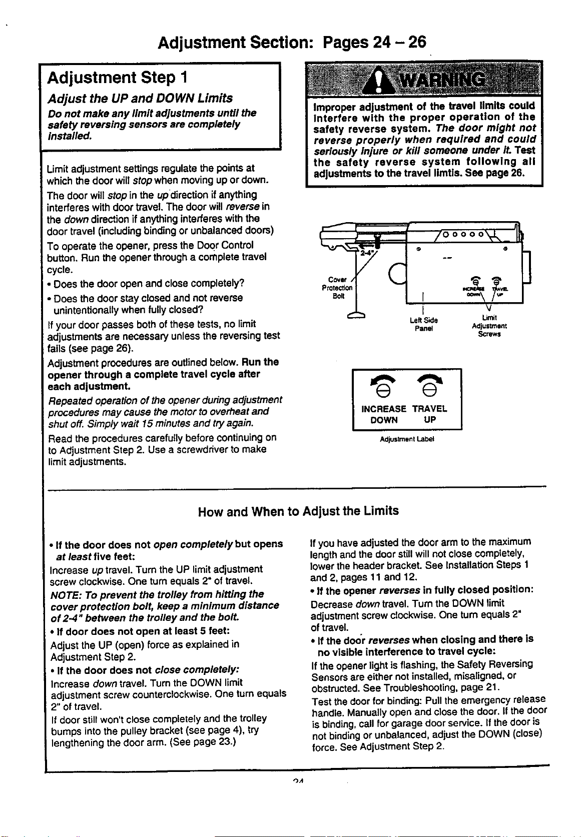
Adjustment Step 1
Adjust the UP and DOWN Limits
Do not make any limit adjustments until the
safety reversing sensors are completely
installed.
Limit adjustment settings regulate the points at
which the door will stop when moving up or down.
The door will stop in the updirsction if anything
interferes with door travel. The door will reverse in
the down direction if anything interferes with the
door travel (including binding or unbalanced doors)
To operate the opener, press the DoQrControl
button. Run the opener through a complete travel
cycle.
• Does the door open and close completely?
• Does the door stay closed and not reverse
unintentionally when fully closed?
If your door passes both ofthese tests, no limit
adjustments are necessary unless the reversing test
fails (see page 26).
Adjustment procedures are outlined below. Run the
opener through a complete travel cycle after
each adjustment.
Repeated operation of the opener during adjustment
procedures may cause the motor to overheat and
shut off. Simp/y wait 15 minutes and try again.
Read the procedures carefully before continuing on
to Adjustment Step 2. Use a screwdriver to make
limit adjustments.
Covet /
Protection
Belt
e-
1!
/ooooo'V,,
• @
.i
I v
Left Side Umit
Panel Adjustment
Screws
INCREASE TRAVEL
DOWN UP
Adjustment Labet
]
How and When to Adjust the Limits
• If the door does not open completely but opens
at least five feet:
Increase up travel. Turn the UP limit adjustment
screw clockwise. One turn equals 2" of travel,
NOTE: To prevent the trolley from hitting the
cover protection bolt, keep a minimum distance
of 2-4 '°between the trolley and the bolt.
• If door does not open at least 5 feet:
Adjust the UP (open) force as explained in
Adjustment Step 2.
• If the door does not close completely:
Increase down travel. Turn the DOWN limit
adjustment screw counterclockwise. One turn equals
2" of travel.
If door still won't close completely and the trolley
bumps into the pulley bracket (see page 4), try
lengthening the door arm. (See page 23.)
If you have adjusted the door arm to the maximum
length and the door stillwill not close completely,
lower the header bracket. See Installation Steps 1
and 2, pages 11 and 12.
• If the opener reverses in fully closed position:
Decrease down travel. Turn the DOWN limit
adjustment screw clockwise. One turn equals 2"
of travel.
• If the door reverses when closing and there is
no visible interference to travel cycle:
If the opener light is flashing, the Safety Reversing
Sensors are either not installed, misaligned, or
obstructed. See Troubleshooting, page 21.
Test thedoor for binding: Pull the emergency release
handle. Manually open and close the door. If the door
is binding,call for garage door service. Ifthe door is
not bindingor unbalanced, adjust the DOWN (close)
force. See Adjustment Step 2.
_A
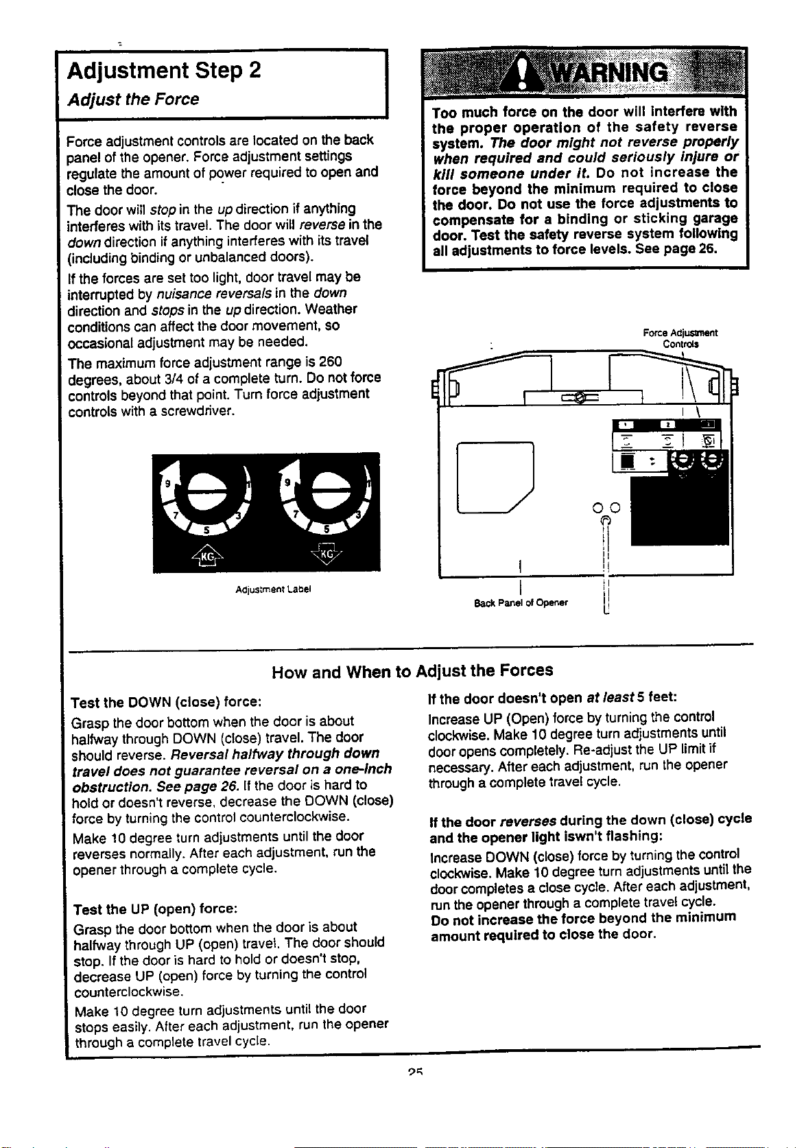
Adjustment Step 2 I
Adjust the Force
Force adjustment controls are located on the back
panel of the opener. Force adjustment settings
regulate the amount of power required to open and
close the door.
The door will stop in the up direction if anything
interferes with its travel. The door will reverse in the
clowndirection if anything interferes with its travel
(including binding or unbalanced doors).
If the forces are set too light, door travel may be
interrupted by nuisance reversals in the down
direction and stops in the up direction. Weather
conditions can affect the door movement, so
occasional adjustment may be needed.
The maximum force adjustment range is 260
degrees, about 3/4 of a complete turn. Do not force
controls beyond that point. Turn force adjustment
controls with a screwdriver.
Too much force on the door will interfere with
the proper operation of the safety reverse
system. The door might not reverse properly
when required and could seriously injure or
kill someone under it. Do not increase the
force beyond the minimum required to close
the door. Do not use the force adjustments to
compensate for a binding or sticking garage
door. Test the safety reverse system following
all adjustments to force levels. See page 26.
ForceAdiuSmlent
Controls
A0justment Label
Back Panel of Opener
U
How and When to Adjust the Forces
Test the DOWN (close) force:
Grasp the door bottom when the door is about
halfway through DOWN (close) travel, The door
should reverse. Reversal halfway through down
travel does not guarantee reversal on a one-inch
obstruction. See page 26. If the door is hard to
hold or doesn't reverse, decrease the DOWN (close)
force by turning the control counterclockwise.
Make 10 degree turn adjustments until the door
reverses normally. After each adjustment, run the
opener through a complete cycle.
Test the UP (open) force:
Grasp the door bottom when the door is about
halfway through UP (open) travet. The door should
stop. If the door is hard to hold or doesn't stop,
decrease UP (open) force by turning the control
counterclockwise.
Make 10 degree turn adjustments until the door
stops easily. After each adjustment, run the opener
through a complete travel cycle.
If the door doesn't open at least 5 feet:
Increase UP (Open) force by turning the control
clockwise. Make 10 degree turnadjustments until
door opens completely. Re-adjust the UP limitif
necessary. After each adjustment, run the opener
through a complete travel cycle.
If the door reverses during the down (close) cycle
and the opener light iswn't flashing:
Increase DOWN (close) force by turning the control
clockwise. Make 10 degree turn adjustments until the
door completes a close cycle. After each adjustment,
runthe opener through a complete travel cycle.
Do not increase the force beyond the minimum
amount required to close the door.
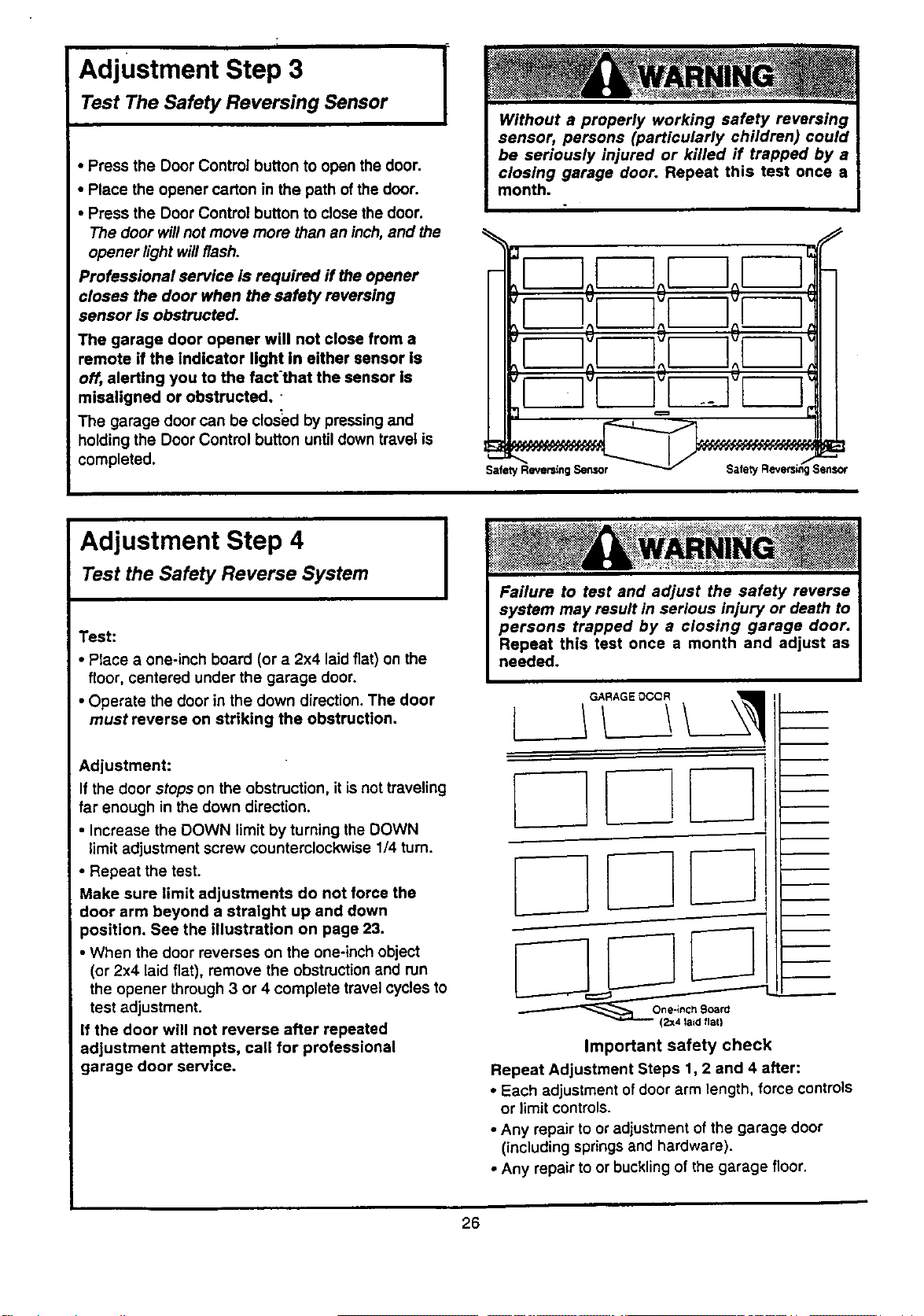
Adjustment Step 3
Test The Safety Reversing Sensor
I
• Press the Door Control button to open the door.
• Place the opener carton in the path of the door.
• Press the Door Control button to close the door.
The door will not move more than an inch, and the
opener light willflash.
Professional service is required ff the opener
closes the door when the safety reversing
sensor is obstructed.
The garage door opener will not close from a
remote if the indicator light In either sensor is
off, alerting you to the fact'that the sensor Is
misaligned or obstructed.
The garage door can be closed by pressing and
holdingthe Door Control button untildown travel is
completed.
IoEZoF--]
I tm;r-] IH
It I;i !;I I;I I:lH
Adjustment Step 4
Test the Safety Reverse System
Test:
• Place a one-inch board (or a 2x4 laid flat) on the
floor, centered under the garage door.
• Operate the door in the down direction. The door
must reverse on striking the obstruction.
Adjustment:
If the door stops on the obstruction, it is not traveling
far enough in the down direction.
• Increase the DOWN limit by turning the DOWN
limit adjustment screw counterclockwise 1/4 turn.
• Repeat the test.
Make sure limit adjustments do not force the
door arm beyond a straight up and down
position. See the illustration on page 23.
• When the door reverses on the one-inch object
(or 2x4 laid flat), remove the obstruction and run
the opener through 3 or 4 complete travel cycles to
test adjustment.
If the door will not reverse after repeated
adjustment attempts, call for professional
garage door service.
I
(2x4 la=d flat)
Important safety check
Repeat Adjustment Steps 1, 2 and 4 after:
• Each adjustment ofdoor arm length, force controls
or limit controls.
• Any repair to or adjustment of the garage door
(including springsand hardware).
• Any repair to or buckling of the garage floor.
26
IMPORTANT SAFETY INSTRUCTIONS
To reduce the risk of severe injury or death to persons:
1. READ AND FOLLOW ALL INSTRUCTIONS.
2. Do not permit children either to operate or to play with the opener. Keep a remote control in a
location inaccessible to children.
3. Operate opener only when the door is in full view and free from any obstruction. Keep the door In
sight until it is completely closed. NO ONE SHOULD CROSS THE PATH OF THE MOVING DOOR.
4. Check safety reversal system monthly. See page 26. The garage door MUST reverse on contact
with a one-inch object (or a 2x4 board laid flat) placed on the floor. If an adjustment is made to
either the force or the limit of travel, both adjustments may be needed and the safety reversal
system must be checked. Failure to properly adjust the opener may result in severe injury or death.
5. If possible, use the emergency release only when the door is in a closed position. Caution should
be taken whenever the disconnect cord is actuated with the door:open. Weak or Eroken springs
may cause the door to fall rapidly, causing injury or death to persons.
6. KEEP GARAGE DOORS PROPERLY BALANCED. See page 3. An improperly balanced doormaynot
reverse when required and could result in severe injury or death. Repairs to cables, spring
assemblies and other hardware must be made by a professional garage door person.
7. Disconnect the electric power from the garage door opener before making any repairs or removing
the covers.
8.SAVE THESE INSTRUCTIONS.
Do not exceed 8 complete cycles of door operation per hour in commercial applications.
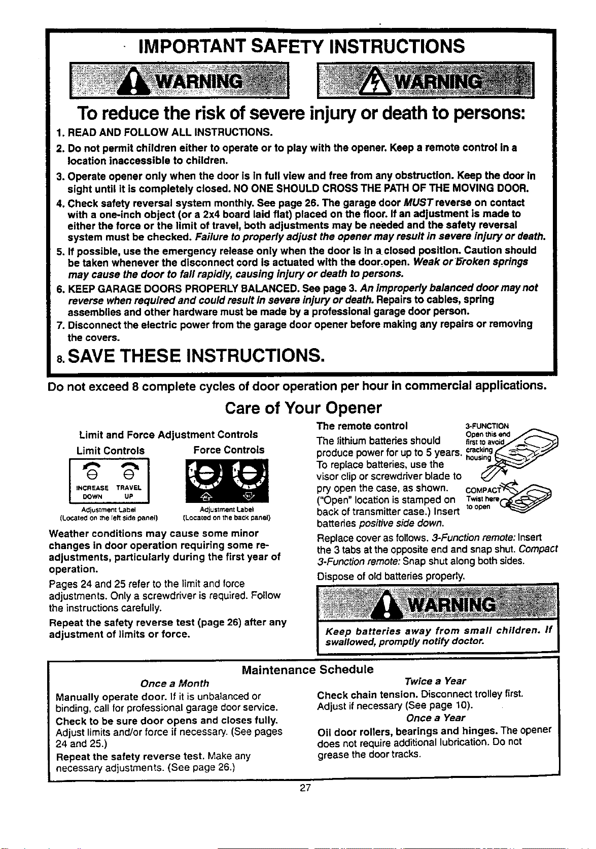
Care of Your Opener
Limit and Force Adjustment Controls
Limit Controls
I
INCREASE TRAVEL
DOWN UP
Adjustment Label
(Located on ;l_e Ieft side panei)
Force Controls
ACjustment Label
(Located on the back panel)
Weather conditions may cause some minor
changes in door operation requiring some re-
adjustments, particularly during the first year of
operation.
Pages 24 and 25 refer to the limit and force
adjustments. Only a screwdriver is required. Follow
the instructions carefully.
Repeat the safety reverse test (page 26) after any
adjustment of limits or force.
The remote control 3-FUNCTION
• . . Ot0en this end
The hthtum battenes should ,rstto,void_
produce power for up to 5 years, c_.€_ng____,,'--_,_,"
To replace batteries, use the ho.._.....--...-
visor clip or screwdriver blade to _ _,"
pry open the case, as shown. COMPACT_
("Open" location isstamped on Twisthere
back of transmitter case.) Insert toopen
batteries positive side down.
Replace cover as follows. 3-Function remote: Insert
the 3 tabs at the opposite end and snap shut•Compact
3-Function remote: Snap shut along both sides.
Dispose of old batteries properly.
Maintenance Schedule
Once a Month
Manually operate door. If it is unbalanced or
binding, call for professional garage door service.
Check to be sure door opens and closes fully.
Adjust limits and/or force if necessary. (See pages
24 and 25.)
Repeat the safety reverse test. Make any
necessary adjustments. (See page 26.)
Twice a Year
Check chain tension. Disconnect trolley first.
Adjust if necessary (See page 10).
Once a Year
Oil door rollers, bearings and hinges. The opener
does not require additional lubrication. Do not
grease the door tracks.
27
Operation of Your Opener
Activate the opener with any of the following:
• The Remote Control: Hold push button down until
the door starts to move.
• The Door Control. Hold push button down until
the door starts to move.
• The Outdoor Key Switch or Keyless Entry.
(See Accessories.)
When the opener is activated with the Safety
Reversing Sensor installed and correctly aligned:
t. If open, the door will close. Ifclosed, itwill open.
2. If closing, the door will reverse.
3. If opening, the door will stop (allowing space for
entry and exit of pets and for fresh air).
4. If the door has been stopped in a partially open
position, it willclose.
5. If obstructed while closing, the door will reverse.
6. If obstructed while opening, the door willstop.
7. The garage door will reverse in the closing cycle,
and the opener lightwill blinkfor 5 seconds, when
the invisible beam is broken. If fullyopen, the door
will not close when the beam is broken. The sensor
has no effect in the opening cycle.
Ifthe sensor is not installed, or is not aligned
correctly, the door won't close from any remote
control. However, you can close the door with the
Door Control, the Outdoor Key Switch, or Keyless
Entry, if you activate them until down travel is
cornp/ete. If you release them too soon, the door will
reverse.
The Opener Light will turn on under the following
conditions: When the opener is initially plugged in;
when the power is interrupted; when the opener is
activated. It willturn off automatically after 4-1/2
minute. Bulb size is 75 watts maximum.
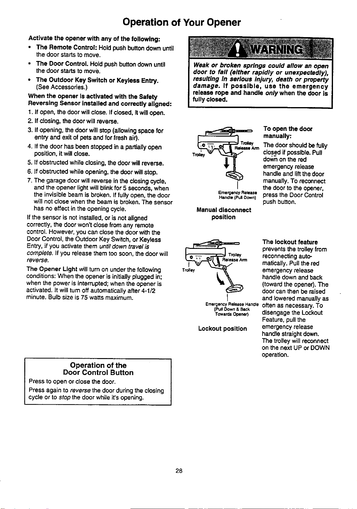
Emergency Release
Hanale (Pull Oown)
Manual disconnect
position
I
Emergency Rek_ase Hanale
(Pull Down & Back
TowardsOpener)
Lockout position
Operation of the
Door Control Button
Press to open or close the door.
Press again to reverse the door during the closing
cycle or to stop the door while it's opening.
To open the door
manually:
The door should befully
closed ifpossible. Pull
down on the red
emergency release
handle and liftthe door
manually. To reconnect
the door to the opener,
press the Door Control
push button.
The lockout feature
prevents the trolley from
reconnecting auto-
matically. Pull the red
emergency release
handle down and back
(toward the opener). The
door can then be raised
and lowered manually as
often as necessary. To
disengage the Lockout
Feature, pull the
emergency release
handle straight down.
The trolley will reconnect
on the next UP or DOWN
operation.
28
Receiver and Remote Control Programming
NOTICE: To complywithFCC ruleS,ad_ustmantormodirK:alfonOfthis
receiverand/or transmitter areprohibited,exseplfor changingthe code
settingor reglacingthe batten/.THERE ARENO OTHER USER
SERVICEABLEPARTS.
The remote control has been factory set to operate
with the large push button. However, you can use
either of the two small buttons, if you prefer. And, the
3-function remote control can also activate additional
garage door openers and/or light controls.
Below are instructionsfor programming your opener
to match the other buttons on your remote controls
and any additional remote controls you may
purchase. See available accessories on page 34.
Children operating or playing with a garage
door opener can Injure themselves or others.
The garage door could close and cause
serious Injury or death. Do not allow children
to operate the door control or remote controls.
A moving garage door could injure or kill
someone under it. Activate the opener only
when you can see the door clearly, it is free of
obstructions, and is properly adjusted.
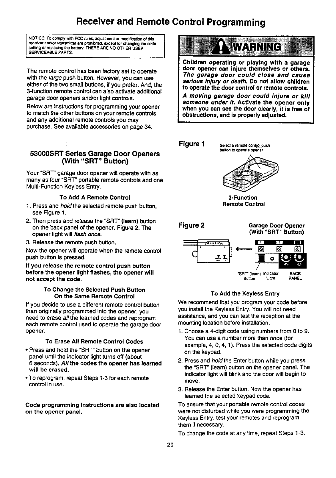
53000SRT Series Garage Door Openers
(With "SRT" Button)
Your "SR'i" garage door opener will operate with as
many as four "SRT" portable remote controls and one
Multi-Function Keyless Entry.
To Add A Remote Control
1. Press and ho/dthe selected remote push button,
see Figure 1.
2. Then press and release the "SRT" (learn) button
on the back panel of the opener, Figure 2. The
opener light will flash once.
3. Release the remote push button.
Now the opener will operate when the remote control
push button is pressed.
If you release the remote control push button
before the opener light flashes, the opener will
not accept the code.
To Change the Selected Push Button
On the Same Remote Control
If you decide to use a different remote control button
than originally programmed into the opener, you
need to erase all the learned codes and reprogram
each remote control used to operate the garage door
opener.
To Erase All Remote Control Codes
• Press and hold the "SRT" button on the opener
panel until the indicator light turns off (about
6 seconds). All the codes the opener has learned
will be erased.
• To reprogram, repeat Steps 1-3 for each remote
control in use.
Code programming instructions are also located
on the opener panel.
Figure I
Selecta remoteconL*2_.push
buttontooperateopener
3-Function
Remote Control
Figure 2 Garage Door Opener
(With "SRT" Button)
-Z-''-
"SRT"(learn) Indicator BACK
Button Light PANEL
29
To Add the Keyless Entry
We recommend that you program your code before
you install the Keyless Entry. You will not need
assistance, and you can test the reception at the
mounting location before installation.
1. Choose a 4-digit code using numbers from 0 to 9.
You can use a number more than once (for
example, 4, 0, 4, 1). Press the selected code digits
on the keypad.
2. Press and hold the Enter button while you press
the "SRT" (learn) button on the opener panel. The
indicator lightwill blink and the door willbegin to
move.
3. Release the Enter button. Now the opener has
learned the selected keypad code.
To ensure that your portable remote control codes
were not disturbed while you were programming the
Keyless Entry, test your remotes and reprogram
them if necessary.
To change the code at any time, repeat Steps 1-3.
Situation
Having a Problem?
Probable Cause & Solution
The opener doesn't
operate from either
the door control or
the remote control:
1. Does the opener have electricpower'?.Plug a lamp intothe outlet. If itdoesn't light,
check the fusebox or the circuitbreaker. (Some outletsare controlledby a wall switch.)
2. Have you disabled all door locks? Review installationinstructionwarnings on
Page 10.
3. Is there a build-upof ice or snow under the door?.The door may be frozen to the
ground. Remove any restriction.
4. The garage door spring may be broken. Have it replaced.
5. Repeated operation may have tripped the overload protector in the motor. Wait
15 minutes. Try again.
Opener operates
from the remote
control but not from
the door control..
1. Is the door control button lit?If not, Remove the bellwire from the opener terminal
screws. Short the red and white terminals by touching bothterminals at the same
time with a piece of wire. Ifthe opener runs, check for a faulty wire connection at the
door control, a short under the staples, or a broken wire.
2. Are the wiring connections correct? Review Step 6, page 16.
The door operates
from the door control,
but not from the
remote controh
1. Does the battery test light glow when the remote controlpush button is pressed? If
not, replace the battery.
2. Your opener needs to re-learn a remote control code. Refer to Instructions on the
opener panel.
3. Program the receiver to match the remote control code.
4. Repeat the receiver programming procedure with all remote controls.
The remote control
has short range:
1. Check the battery test light. If the light isdim, change the battery.
2. Change the location of the remote control in your car.
3. Check to be sure the antenna on the back panel of opener extends fully downward.
4. Some installations may have shorter range due to a metal door, foil backed
insulation, or metal garage siding.
Install Antenna Kit, Part No. 41A3504, to increase range.
Opener noise is
disturbing in living
quarters of home:
If operational noise isa problem because of proximity of the opener to the living
quarters, the Vibration Isolator Kit 41 A3263 can be installed.This kit was designed to
minimize vibration to the house and is easy to install.
The garage door
opens and closes
by itself:
1. Be sure thatall remote control push buttons and battery indicator lightS are off.
2. Remove the bell wire from thedoor controlterminalsand operate from the remote
controlonly. Ifthis solves the problem, the door controlisfaulty (replace), or there isan
intermittentshorton the wire between the door controland the opener.
3. Clear memory and reprogramall remote controls.
The door doesn't
open completely:
The door stops but
doesn't close
completely:
1.
up force. See page 25.
2. Is something obstructingthe door?.Remove the obstructionor repair the door.
3. If door opens at least 5 feet, the travel limits may need to be increased. One turn
equals 2 inches of travel. See page 24.
Repeat the safety reverse test after the adjustment is complete.
If the door has been working properly but now doesn't open all the way, increase the
Review the travel limits adjustment procedures on page 24.
Repeat the safety reverse test after any adjustment of door arm length, close force
or down limit.
3O
Having a Problem? (continued)
Situation
Probable Cause & Solution
The door opens but
won't close:
1. If the opener light blinks, check the safety reversing sensor. See page 21.
2. If the opener lightdoes not blink and it isa new installation,check the down force.
See Adjustment Step 2, page 25. For an existing installation, see below.
Repeat the safety reverse test after the adjustment is complete•
The door reverses for
no apparent reason
and opener light
doesn? blink:
1. Is something obstructingthe door?. Pullthe emergency release handle. Operate the
door manually. If itis unbalanced or binding, call for professional garage door service.
2. Clear any ice or snow from the garage floor area where the door closes.
3. Review the force adjustment procedures on page 25.
4. If door reverses in the fullyclosed position, decrease the travel limits (page 24).
Repeat safety reverse test after the adjustment is complete. The need for
occasional adjustment of the force and limit settings is normal. Weather
conditions in particular can affect door travel.
The door reverses for
no apparent reason
and opener light
blinks for 5 seconds
after reversing:
Check the safety reversing sensor. Remove any obstruction or align the receiving eye.
See page 21.
The opener light
•.. doesn't turn on:
Replace the lightbulb (75 watts maximum). Use a standard neck garage door opener
bulb ifregular bulbbums out.
•.. doesn't turn off:
There may be a defective ground at the ceiling or wall receptacle. The unit must be
grounded.
The opener strains or
maximum force is
needed to operate
door:
The door may be out ofbalance or the springsare broken. Close the door and usethe
emergency release handle to disconnectthetrolley.Open and close the door manually.
A propedybalanced door willstay in any pointoftravel whilebeing supported entirelyby its
springs. Ifitdoes not,disconnectthe opener and callfor professional garage door service.
Do not increase the force to operate the opener.
The opener motor
hums briefly, then
won't work:
1.
2.
The garage door springs are broken. See above.
If the problem occurs on the firstoperation ofthe opener, door may be locked. Disable
the doorlock. If the chain was removed and re-installed, the motor may be out of phase.
Remove the chain; cycle the motor to the down position. Observe the ddve sprocket.
When it turns in a clockwise direction and stops in the down position, reinstall the chain.
Repeat the safety reverse test after the adjustment is complete•
The opener won't
operate due to
power failure:
1. Use the emergency release rope and handle to disconnect the trolley. The door can
be opened and closed manually. When power is restored, press the door control
button and trolley will automatically reconnect (unless trolley is in lockout position.)
See page 28.
2. The Emergency Key Release accessory (for use on garages with no service door)
disconnects the trolley from outside the garage incase of power failure.
The chain droops
or sags:
It is normal for the chain to droop slightly in the closed door position. Use the
emergency release rope and handle to disconnect the trolley. If the chain returns to the
normal height when the trolley is disengaged and the door reverses on a
one-inch board (or a 2x4 laid flat), no adjustments are needed. (See page 10.)
31
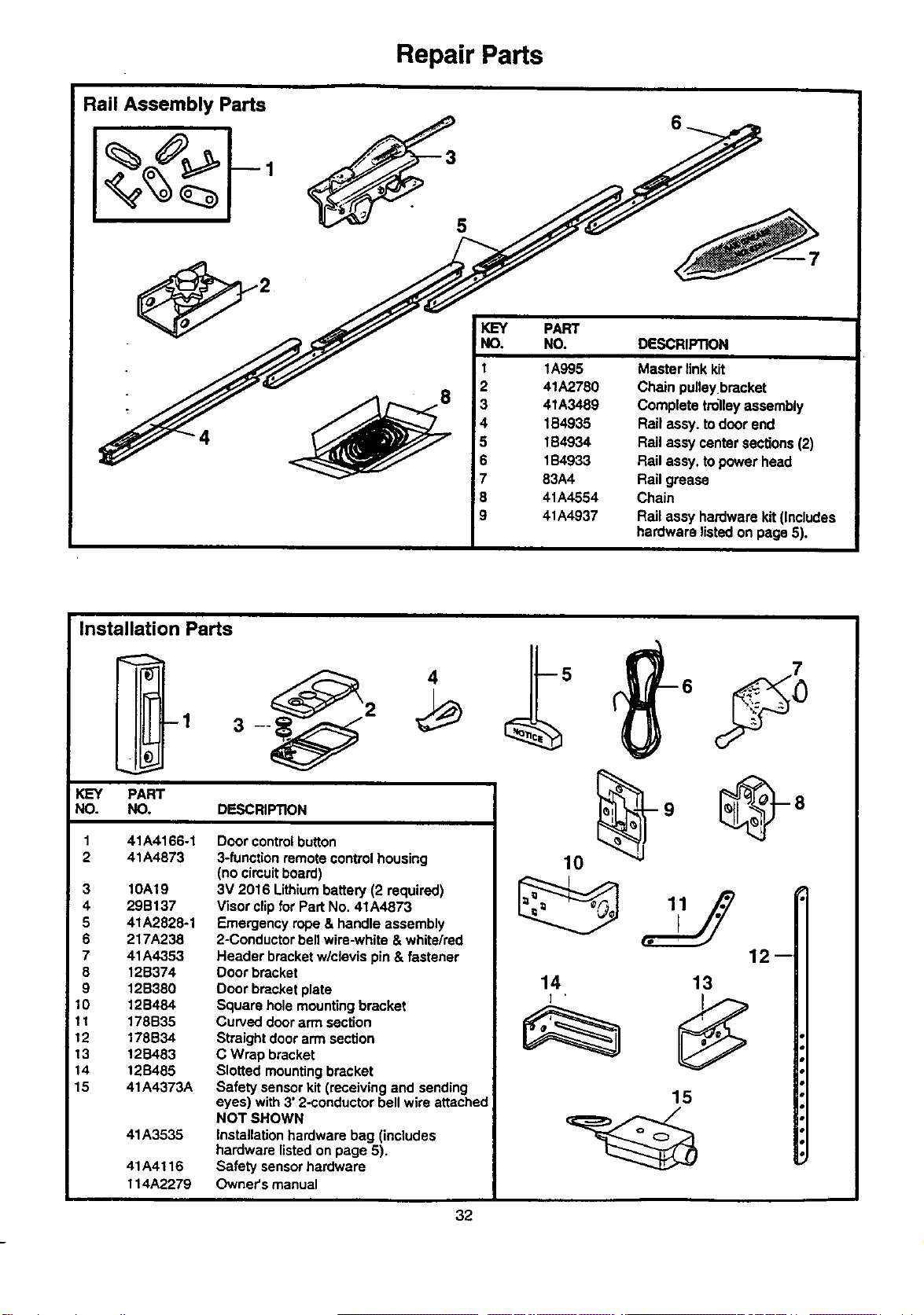
Repair Parts
Rail Assembly Parts
4
5
IKEY
!NO.
i
I
2
3
4
5
6
7
8
9
PART
NO. DESCRIPTION
1A995
41A2780
4tA3489
1B4935
1B4934
1B4933
83A4
41A4554
41A4937
Masterlinkkit
Chain pulleybracket
Completetrolleyassembly
Railassy,todoorend
RailassycentersecUons(2)
Railassy.topowerhead
Railgrease
Chain
Railaseyhardwarekit(Includes
hardwarelistedon page5),
Installation Parts
-1
2
__.
KEY PART
NO. NO. DESCRIPTION
41A4166-1
41A4873
3 10A19
4 29B137
5 41A2828-1
6 217A238
7 41A4353
8 12B374
9 12B380
10 12B484
11 178B35
12 178B34
13 12B483
14 12S485
15 41A4373A
41A3535
41A4116
114A2279
Door control button
3-function remote control housing
(no cimuit board)
3V 2016 Lithium battew (2 required)
Visor clip for Part No. 41A4873
Emergency rope & handle assembly
2-Conducter bell wire-white & white/red
Header bracket w/clevis pin & fastener
Door bracket
Door bracket plate
Square hole mounting bracket
Curved door arm section
Straight door arm section
C Wrap bracket
Slotted mounting bracket
Safety sensor kit (receiving and sending
eyes) with 3' 2-conductor bell wire attached
NOT SHOWN
Installation hardware bag (includes
hardware listed on page 5).
Safety sensor hardware
Owner's manual
12--
14
] .
13
15
32
1 41C5069
=2 144B18
i 3 41C4470
5
6
7
8
9
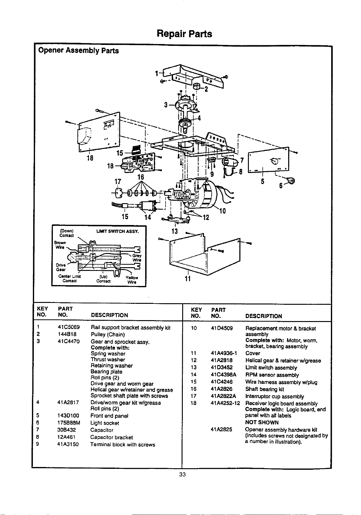
Repair Parts
Opener Assembly Parts
r--p_u"_.._==" ,I, , I g LJL-8 - I L.
17 ]_ =rL._-.-_ - ,
15 14 _'_ 12
Wire !
co_,== co°_== Wi,o 11
KEY PART KEY PART
NO. NO. DESCRIPTION NO. NO. DESCRIPTION
Rail support bracket assembly kit 10 41D4509 Replacement motor & bracket
41A2817
1430100
175B88M
30B432
12A461
41A3150
Pulley (Chain)
Gear and sprocket assy.
Complete with:
Spdng washer
Thrust washer
Retaining washer
Bearing plate
Roll pins (2)
Drive gear and worm gear
11
12
13
14
15
41A4936-1
41A2818
41D3452
41C4398A
41C4246
assembly
Complete with: Motor,worm,
bracket, bearing assembly
Cover
Helical gear & retainer w/grease
Limit switch assembly
RPM sensor assembly
Wire harness assembly w/plug
Helical gear wlretainer and grease
Sprocket shaft plate with screws
Ddve/won'n gear kit wlgrease
Roll pins (2)
Front end panel
Lightsocket
Capacitor
Capacitor bracket
Terminal block with screws
16
17
18
41A2826
41A2822A
41A4252-12
41A2825
Shaft bearingkit
IntemJptor cup assembly
Receiver logicboard assembly
Complete with: Logic board, end
panel with all labels
NOT SHOWN
Opener assemblyhardware kit
(includes screws not designated by
a number in illustration).
33
Accessories
Sears offers many useful accessories fro your garage door opener. They are illustrated below with
Sears modal numbers and descdptions.
139.53702 139.53879
139.53703
53589
139.53709
Emergency Key Release:
Required for a garage with NO
access door. Enables
homeowner to open garage
door manually from outside by
disengaging trolley.
Outdoor Key Switch:
Operates the garage door
automatically from outside when
remote control is not handy.
Support Brackets:
For finished ceilings or where
additional support is required,
based on garage construction.
Includes brackets and fastening
hardware.
139.03859
139.53876
3-Function Remote Control:
includes visor clip.
Compact 3-Functlon Remote
Control: -
With loop for attaching key ring.
Multi-Function Keyless Entry:
Enables homeowner to operate
garage door opener from outside
by entering a 4-digit code on
specially designed keypad.
Door Clearance Brackets:
(For Sectional Doors Only)
Replaces top brackets and rollers on door to reduce height of door travel.
For use when installingopener in garage with low headroom clearance.

Index
Access Door/Emergency Key Release Accessory ....................................................................................... 4, 34
Chain Tension ............................................................................................................................................ 4, 10, 31
Electrical Safety Warnings .................................................................................................................. 2, 10, 18, 27
Garage Door
Testing for balance, binding and sucking................................................................................................... 3, 25, 27
Determining high point of travel: .......................................................................................................................... 11
Disabling existing locks......._............................................................................................................................ 3, 10
Door clearance brackets (for garages with low headroom) ........................................................................... 11, 34
Force Controls
Adjustment procedures ..................................................................................................................................... 25
Problems that might require force adjustments .......................................................................................... 30, 31
Safety warnings ................................................................................................................. =........................ 25, 27
Door hardware ...................................................................................................................... .'..-3,10, 11, 16, 27, 28
Maintenance Instruction Label ....................................................................................................................... 1O,16
Reinforcement requirements ................................................................................................... ;....................... 4, 22
Removing all ropes .......................................................................................................................................... 3, 10
Possible door damage ............................................................................................................................... 3, 14, 22
Travel Limits
Adjustment procedures ..................................................................................................................................... 24
Problems that might require limit adjustments ............................................................................................ 30, 31
Safety warnings ......................................................................................................................................... .24, 27
Manual (Emergency) Release Rope & Handle
Lockout feature ................................................................................................................................................... 28
Manual disconnect ...................... .................................................................................................................. 28, 31
Safety warnings ................................................................................................................................ 10, 17, 27, 28
Opener Terminals
Door control connections .................................................................................................................................... 16
Safety reversing sensor connections .................................................................................................................. 21
Operational Noise
Sprocket noise .................................................................................................................................................... 10
Vibration noise (isolator kit) ................................................................................................................................ 30
Receiver and Remote Controls
Programming the receiver ............................................... ;................................................................................... 29
Erasing all codes ................................................................................................................................................. 29
Safety warning ..................................................................................................................................................... 29
Activating other openers ...................................................................................................................................... 29
Problems with remote control operation .............................................................................................................. 30
Safety Reverse Test Procedure .......................................................................................................................... 26
Testing required .................................................................................... :........................................... 10, 26, 30, 31
Safety reverse system problems
Securing header bracket to wall ....................................................................................................................... 11
Adjusting travel limits........................................................................................................................................ 24
Applying excessive force on the door ............................................................................................................... 25
Buckling or uneven floor ..................................................................................................................................... 4
Safety Warnings ............................................... 2, 3, 8, g, 10, 11, 14, 15, 16, 17, 18, 19, 22, 24, 25, 26, 27, 28, 29
User Instruction Label for garage wall ........................................................................................................ 10, 16

For professional Installatlon
Call 24 hours a day, 7 days a week
1-800-865-6500
For the repair or replacement parts you need
Call 7 am - 7 pm, 7 days a week
1-8OO-366-PART
(1-800-366-7278)
For in-home major brand repair service
Call 24 hours a day, 7 days a week
1-800-4-REPAIR
(1-800-473-7247)
For the location of a Sears Repair Service Center in your area
: Call 24 hours a day, 7 days a week
1-800-488-1222
For information on purchasing a Sears Maintenance Agreement or to inquire
about an existing Agreement
Call 9 am - 5 pro, Monday-Saturday
1-800-827-6655
The model number label is located on the front end panel of your opener.
When requesting service or ordering parts, always give the following
information:
• Product Type
• Model Number
• Part Number
• Part Description
SEARS
America's Re_air Specialists
SEARS WARRANTY
FULL gO-DAY WARRANTY ON GARAGE DOOR OPENER
For 90 days from the date of purchase, Sears will repair _is Garage Door Opener, free of charge, if defective in material or workmanship.
LIMITED WARRANTY
From the 91st day until one year from the date of purchase, Sears will furnish replacement parts for any defec:ive parts, free of charge.
You pay for labor.
LIMITATION ON UABILITY
SEARS WILL NOT BE UABLE FOR LOSS OR DAMAGE TO PROPERTY OR ANY INCIDENTAL OR CONSEQUENTIAL LOSS OR
EXPENSE FROM PROPERTY DAMAGE DUE DIRECTLY OR INDIRECTLY FROM THE USE OF THIS PRODUCT. Same states do
not allow tha exclusion or limitation of incidental or consequential damages, so the above limitation or exclusion may not apply to you.
This warranty does not cover light bulbs or repair parts necessary because of operator abuse or negligence, including the failure to
install, adjust and operate this garage door opener according to instructions contained in the owner's manual.
WARRANTY SERVICE IS AVAILABLE BY SIMPLY CONTACTING THE NEAREST SEARS CENTER/DEPARTMENT IN THE UNITED
STATES.
This warranty applies only while this product is in use in the United States,
This warranty gives you specific legal rights, and you may also have other dghts which vary from state to state.
Sears, Roebuck and Co., Dept. 817WA, Hoffman Estates, IL 60179
114A2279B ©1998, All Rights Reserved Printed in Mexico