USER’S GUIDE
For future reference, record the serial
number of your display monitor in the
space below:
SERIAL No.
The serial number is located on the
rear cover of the monitor.
AUTO-SCANNING WITH DIGITAL CONTROL
LCD COLOR DISPLAY MONITOR
MultiSync
®
LCD1800
™
SELECT
ADJUST
OSD OFF
-
+
SIGNAL A/B
Supplying Windows 95/98 INF File download service,new products
information, etc.
Internet Home Page: http://www.necmitsubishi.com/
- 1-1 -
ENGLISH
CAUTION
Do not remove the monitor cabinet as this can
expose you to very high voltages and other hazards.
Trademark
IBM, PC, PS/2, PS/V, Personal System/2 are registered trade-
marks of International Business Machines Corp.
Apple Macintosh is a registered trademark of Apple Computer, Inc.
Quadra is a trademark of Apple Computer, Inc.
UNIX is a registered trademark in the United States and other
countries, licensed exclusively through X/Open Company Limited.
E
NERGY
S
TAR
is a U.S. registered mark.
NEC is registered trademark of NEC Corporation.
All other trademarks or registed trademarks are property of their
respective owners.
© 2000 NEC-MITSUBISHI Electronics Display of America, Inc.
CONTENTS
MANUFACTURER DECLARATION FOR
CE-MARKING:
We, NEC-MITSUBISHI ELECTRIC VISUAL SYS-
TEMS CORPORATION declare under our sole
responsibility, that this product is in conformity with
the following standards:
EN60950
EN55022 Class B
EN50082-1
EN61000-3-3
following the provisions of:
73/23/EEC Low Voltage Directive
89/336/EEC EMC Directive
WARNING!
This product is not designed for use in life support
devices and NEC-MITSUBISHI ELECTRIC VISUAL
SYSTEMS CORPORATION makes no representa-
tions to the contrary. Life support devices are those
devices which are used to measure, diagnose, or
evaluate the tissue, systems or functions of the human
body; or other devices employed to support or sustain
life or good health.
1. INTRODUCTION.................................................. 1-2
1.1 Features ..................................................... 1-2
1.2 Internal Preset Memory Capability............. 1-2
1.3 IPM
™
(Intelligent Power Manager) System . 1-3
1.4 DDC ........................................................... 1-3
1.5 Display Mode Selection ............................. 1-3
1.6 Auto Adjustment Function.......................... 1-3
1.7 Screen Auto Expand Function ................... 1-3
1.8 Signal Input Connector
Auto Selection Function ............................. 1-3
1.9 Auto Brightness Function........................... 1-3
1.10 AccuColor
®
Control Function ..................... 1-4
1.11 Location Considerations ............................ 1-4
1.12 Cleaning Your Monitor ............................... 1-4
1.13 Unpacking .................................................. 1-4
1.14 Tilt Base ..................................................... 1-4
Screen Position Adjustment....................... 1-4
1.15 Quick Operation Chart ............................... 1-5
2. PART NAME ........................................................ 1-6
2.1 Control Names ........................................... 1-6
2.2 Function ..................................................... 1-6
3. INSTALLATION AND CONNECTION .................. 1-7
3.1 AC Power Connection................................ 1-7
3.2 Signal Cable Connection ........................... 1-7
3.2.1 Connecting to Any IBM VGA Compatible
System .................................................. 1-7
3.2.2 Connecting to An Apple Macintosh
Computer .............................................. 1-8
3.2.3 Connecting to Two Computers.............. 1-8
4. AUTO SETUP FUNCTION ................................... 1-9
5. OSM
™
(On Screen Manager) FUNCTIONS .......... 1-9
5.1 Adjustment Items ....................................... 1-10
5.2 CONTROL LOCK Mode Operation ............ 1-11
6. TROUBLESHOOTING ......................................... 1-12
7. SPECIFICATIONS ............................................... 1-13
LIMITED WARRANTY ............................................... 1-14
- III -
RADIO INTERFERENCE REGULATIONS STATE-
MENT FOR U.S.A.
This equipment has been tested and found to comply
with the limits for a Class B digital device, pursuant to
Part 15 of the FCC Rules. These limits are designed to
provide reasonable protection against harmful interfer-
ence in a residential installation. This equipment gen-
erates, uses and can radiate radio frequency energy
and, if not installed and used in accordance with the
instructions, may cause harmful interference to radio
communications. However, there is no guarantee that
interference will not occur in a particular installation. If
this equipment does cause harmful interference to
radio or television reception, which can be determined
by turning the equipment off and on, the user is encour-
aged to try to correct the interference by one or more of
the following measures:
- Reorient or relocate the receiving antenna.
- Increase the separation between the equipment
and receiver.
- Connect the equipment into an outlet on a circuit
different from that to which the receiver is con-
nected.
- Consult the dealer or an experienced radio/TV tech-
nician for help.
NO USER SERVICEABLE PARTS IN-
SIDE. DO NOT ATTEMPT TO MODIFY
THIS EQUIPMENT. IF MODIFIED, YOUR
AUTHORITY TO OPERATE THIS EQUIP-
MENT MIGHT BE VOIDED BY FCC.
この装置は、情報処理装置等電波障害自主規制協議会
(VCCI)の基準に基づくクラスB情報技術装置です。この装置
は、家庭環境で使用することを目的としていますが、この
装置がラジオやテレビジョン受信機に近接して使用される
と、受信障害を引き起こすことがあります。
取扱説明書に従って正しい取り扱いをしてください。
As an ENERGY STAR Partner, NEC-MITSUBISHI
Electronics Display of America, Inc. has determined
that this product meets the E
NERGY STAR guide-
lines for energy efficiency.
Declaration of Conformity - United States only
Product Name:
18.1 in. (46cm) Color Display
Monitor
Type: LSA831W
Brand Name: NEC
This device complies with Part 15 of the FCC Rules.
Operation is subject to the following two conditions:
(1) this device may not cause harmful interference, and
(2) this device must accept any interference received,
including interference that may cause undesired op-
eration.
For questions regarding this declaration, contact:
NEC-Mitsubishi Electronics Display of
America, Inc.
1250 N. Arlington Heights Road,
Suite 500 Itasca, IL 60143
or, call 630-467-5000
To identify this product, refer to the model number found
on the product.

- IV -
Congratulations!
You have just purchased a TCO’99 approved and labelled
product! Your choice has provided you with a product
developed for professional use. Your purchase has also
contributed to reducing the burden on the environment and
also to the further development of environmentally adapted
electronics products.
Why do we have environmentally labelled computers?
In many countries, environmental labelling has become an
established method for encouraging the adaptation of
goods and services to the environment. The main problem,
as far as computers and other electronics equipment are
concerned, is that environmentally harmful substances
are used both in the products and during their manufacture.
Since it is not so far possible to satisfactorily recycle the
majority of electronics equipment, most of these potentially
damaging substances sooner or later enter nature.
There are also other characteristics of a computer, such as
energy consumption levels, that are important from the
viewpoints of both the work (internal) and natural (external)
environments. Since all methods of electricity generation
have a negative effect on the environment (e.g. acidic and
climate-influencing emissions, radioactive waste), it is vital
to save energy. Electronics equipment in offices is often
left running continuously and thereby consumes a lot of
energy.
What does labelling involve?
This product meets the requirements for the TCO’99 scheme
which provides for international and environmental labelling
of personal computers. The labelling scheme was
developed as a joint effort by the TCO (The Swedish
Confederation of Professional Employees), Svenska
Naturskyddsforeningen (The Swedish Society for Nature
Conservation) and Statens Energimyndighet (The Swedish
National Energy Administration).
Approval requirements cover a wide range of issues:
environment, ergonomics, usability, emission of electric
and magnetic fields, energy consumption and electrical
and fire safety.
The environmental demands impose restrictions on the
presence and use of heavy metals, brominated and
chlorinated flame retardants, CFCs (freons) and chlorinated
solvents, among other things. The product must be prepared
for recycling and the manufacturer is obliged to have an
environmental policy which must be adhered to in each
country where the company implements its operational
policy.
The energy requirements include a demand that the
computer and/or display, after a certain period of inactivity,
shall reduce its power consumption to a lower level in one
or more stages. The length of time to reactivate the
computer shall be reasonable for the user.
Labelled products must meet strict environmental demands,
for example, in respect of the reduction of electric and
magnetic fields, physical and visual ergonomics and good
usability.
Below you will find a brief summary of the environmental
requirements met by this product. The complete
environmental criteria document may be ordered from:
TCO Development
SE-114 94 Stockholm, Sweden
Fax: +46 8 782 92 07
Email (Internet): [email protected]
Current information regarding TCO’99 approved and
labelled products may also be
obtained via the Internet, using the address:
http://www.tco-info.com/
Environmental requirements
Flame retardants
Flame retardants are present in printed circuit boards,
cables, wires, casings and housings. Their purpose is to
prevent, or at least to delay the spread of fire. Up to 30%
of the plastic in a computer casing can consist of flame
retardant substances. Most flame retardants contain
bromine or chloride, and those flame retardants are
chemically related to another group of environmental toxins,
PCBs. Both the flame retardants containing bromine or
chloride and the PCBs are suspected of giving rise to
severe health effects, including reproductive damage in
fish-eating birds and mammals, due to the bio-accumulative
*
processes. Flame retardants have been found in human
blood and researchers fear that disturbances in foetus
development may occur.
The relevant TCO’99 demand requires that plastic
components weighing more than 25 grams must not contain
flame retardants with organically bound bromine or chlorine.
Flame retardants are allowed in the printed circuit boards
since no substitutes are available.
Cadmium
**
Cadmium is present in rechargeable batteries and in the
colour-generating layers of certain computer displays.
Cadmium damages the nervous system and is toxic in high
doses. The relevant TCO’99 requirement states that
batteries, the colour-generating layers of display screens
and the electrical or electronics components must not
contain any cadmium.
Mercury
**
Mercury is sometimes found in batteries, relays and
switches. It damages the nervous system and is toxic in
high doses. The relevant TCO’99 requirement states that
batteries may not contain any mercury. It also demands
that mercury is not present in any of the electrical or
electronics components associated with the labelled unit.
CFCs (freons)
The relevant TCO’99 requirement states that neither CFCs
nor HCFCs may be used during the manufacture and
assembly of the product. CFCs (freons) are sometimes
used for washing printed circuit boards. CFCs break down
ozone and thereby damage the ozone layer in the
stratosphere, causing increased reception on earth of
ultraviolet light with e.g. increased risks of skin cancer
(malignant melanoma) as a consequence.
Lead
**
Lead can be found in picture tubes, display screens,
solders and capacitors. Lead damages the nervous system
and in higher doses, causes lead poisoning. The relevant
TCO´99 requirement permits the inclusion of lead since no
replacement has yet been developed.
*
Bio-accumulative is defined as substances which
accumulate within living organisms
**
Lead, Cadmium and Mercury are heavy metals which
are Bio-accumulative.
- 1-2 -
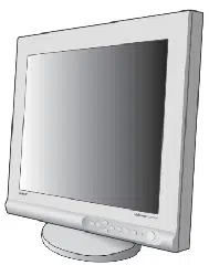
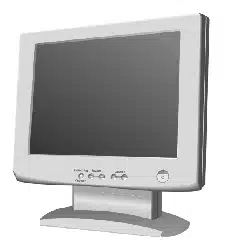
Congratulations on your purchase of the MultiSync
LCD1800
™
high resolution color LCD monitor.
This guide tells you how to connect, adjust and care for
your MultiSync LCD1800 monitor. This guide also pro-
vides technical specifications and instructions for trouble-
shooting any basic problems you may experience with
your monitor.
1.1 Features
The MultiSync LCD1800 is a 46cm/18.1", intelligent,
microprocessor-based LCD monitor compatible with most
analog RGB (Red, Green, Blue) display standards.
The monitor provides crisp text and vivid color graphics
with both PC and Macintosh platforms.
Dual Inputs
Offers dual inputs, allowing you to connect the monitor
to two systems. You can easily switch between com-
puters with a touch of a button on the front control
panel.
Reduced Footprint
Provides the ideal solution for environments requiring
superior image quality but with size and weight limita-
tions. The monitor’s small footprint and low weight
allow it to be moved or transported easily from one
location to another.
AccuColor
®
Control System
Allows you to adjust the colors on your screen and
customize the color accuracy of your monitor to a
variety of standards.
OSM
™
(On-Screen Manager) Controls
Allow you to quickly and easily adjust all elements of
your screen image via simple to use on-screen menus.
ErgoDesign
®
Features
Enhance human ergonomics to improve the working
environment, protect the health of the user and save
money. Examples include OSM controls for quick and
easy image adjustments, tilt/swivel base for preferred
angle of vision, small footprint and compliance with
MPRII guidelines for lower emissions.
Plug and Play
The Microsoft
®
solution with the Windows
®
operating
system facilitates setup and installation by allowing
the monitor to send its capabilities (such as screen
size and resolutions supported) directly to your com-
puter, automatically optimizing display performance.
IPM
™
(Intelligent Power Manager) System
Provides innovative power-saving methods that allow
the monitor to shift to a lower power consumption level
when on but not in use, saving two-thirds of your
monitor energy costs, reducing emissions and lower-
ing the air conditioning costs of the workplace.
Multiple Frequency Technology
Automatically adjusts monitor to the display card’s
scanning frequency, thus displaying the resolution
required.
FullScan
™
Capability
Allows you to use the entire screen area in most
resolutions, significantly expanding image size.
VESA Standard Mounting Interface
Allows users to connect their MultiSync monitor to any
VESA standard third party mounting arm or bracket.
Allows for the monitor to be mounted on a wall or an arm
using any third party compliant device.
XtraView
®
Allows the user to be able to see the monitor from any
angle (160 degrees). Provides full 160° viewing angles
either up, down, left or right.
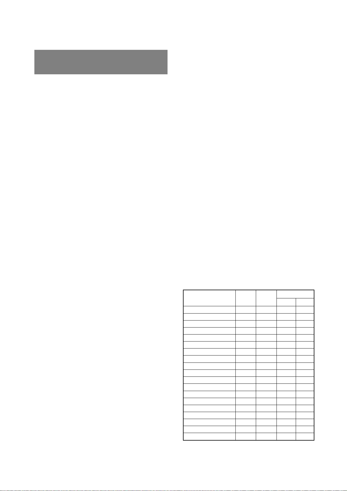
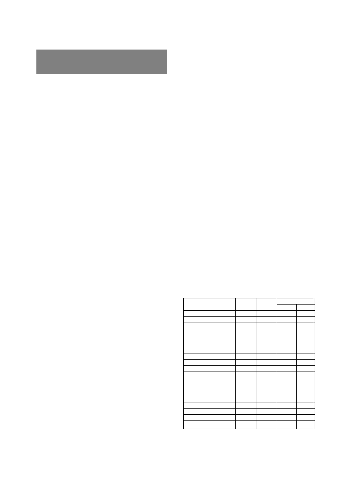
1.2 Internal Preset Memory Capability
To minimize adjustment needs, the factory has preset
popular display standards into the monitor, as shown in
Table 1. If any of these display standards are detected, the
picture size and centering are automatically adjusted. All
of the factory presets may be overwritten by adjusting the
user controls. The monitor is capable of automatically
storing up to 7 additional display standards. The new
display information must differ from any of the existing
display standards by at least 1kHz for the horizontal scan
frequency or 1Hz for the vertical scan frequency or the sync
signal polarities must be different.
Table 1. Memory Buffer Factory Presets
Polarity
Resolution
Fh(kHz)
Fv (Hz) H V
640 x 480 N.I. 35.0 66.7
--
832 x 624 N.I. 49.7 74.6
--
1152 x 870 N.I. 68.7 75.0
--
640 x 350 N.I. 31.4 70.0
+
-
640 x 480 N.I. 31.5 59.9
--
640 x 480 N.I. 37.5 75.0
--
640 x 480 N.I. 43.3 85.0
--
720 x 400 N.I. 31.5 70.0
-
+
800 x 600 N.I. 37.9 60.3
++
800 x 600 N.I. 48.1 72.2
++
800 x 600 N.I. 46.9 75.0
++
800 x 600 N.I. 53.7 85.0
++
1024 x 768 N.I. 48.4 60.0
--
1024 x 768 N.I. 56.5 70.1
--
1024 x 768 N.I. 58.1 72.1
--
1024 x 768 N.I. 60.2 75.0
++
1024 x 768 N.I. 68.7 85.0
++
1280 x 1024 N.I. 64.0 60.0
--
1280 x 1024 N.I. 80.0 75.0
++
1
1 INTRODUCTION
- 1-3 -
ENGLISH
1.4 DDC
The monitor includes the DDC
TM
2B feature, more com-
monly known as "Plug & Play". DDC(Display Data Chan-
nel) is a communication channel over which the monitor
automatically informs the computer about its capabililties
(e.g. each supported resolution with its corresponding
timing).
DDC is routed through previously unused pins of the 15-
pin VGA connector.
The system will perform "Plug and Play" feature if both,
monitor and computer, implement the DDC protocol.
When a Plug and Play computer starts, it identifies the
monitor and loads the appropriate driver automatically. If
the computer does not have the driver installed, a dialog
box will appear asking where the information can be
found. The latest drivers may be downloaded from the
"Support" section of the NEC-MITSUBISHI Website lo-
cated at:
http://www.necmitsubishi.com/
1.5 Display Mode Selection ("DISPLAY MODE"
P1-10)
The following two display modes are available. You can
select either mode suitable to your work, on the OSM
™
( P1-10).
Text Mode
The contrast is emphasized more than the accuracy of the
color appearance in this mode. This mode is suitable for
such works that the accuracy of the displayed colors is not
so important, e.g. document making, calculation, data-
base making, etc.
Graphic Mode
The accuracy of the color tone is emphasized in this mode.
This mode is suitable for such works where the accuracy
of the displayed colors is important, e.g. photograph
processing, making of illustration, etc.
• When you receive the monitor, "DISPLAY MODE" is
set to "GRAPHIC" mode.
• Before selecting "Graphic Mode", perform "AUTO
SETUP". If not, the displayed screen may become too
bright.
• Before using "Color Matching", set the "COLOR" to
"NATIVE", "DISPLAY MODE" to "GRAPHIC".
( P1-10)
1.7 Screen Auto Expand Function ("EXPAND"
P1-10)
This function is to expand the screen automatically. By a
smoothing function, you can get a clear screen when the
screen is expanded by this function. This function is
available in case that a signal of 1024 dots by 768 lines or
lower is inputted to the monitor.
• With some resolution, even if it meets the condition
above, the screen is not expanded fully to the screen
area.
• With some signal type inputted, the screen is not
expanded vertically or horizontally.
• With some resolution, the image may be slightly
blurred.
1.8 Signal Input Connector Auto Selection Func-
tion ("AUTO SELECT" P1-11)
This function is to select the signal input connector which
is in the active condition automatically. In case that two
computers are connected with the monitor, another com-
puter will be selected automatically when the first selected
computer went into a power saving mode.
• When you receive the monitor, "AUTO SELECT" is set
to "ON".
1.3 IPM
™
(Intelligent Power Manager) System
The monitor has a IPM(Intelligent Power Manager) Sys-
tem which reduces the power consumption of the monitor
when not in use.
When the horizontal sync signal and/or vertical sync signal
is off, after about 10 seconds the monitor is switched to a
power saving mode which reduces the monitor power
consumption to less than 3W. When the monitor is in
power saving mode, the screen is off and the power
indicator will illuminate at amber.
After the signals are restored, picture will be displayed
within about 3 seconds.
Check your computer's manual for setting this function.
1.9
Auto Brightness Function ("AUTO BRIGHTNESS"
P1-10)
This function is to adjust the brightness automatically to
the extent of white display area, against dazzle.
1.6 Auto Adjustment Function ("AUTO ADJUST"
P1-10)
This function is to adjust "CLOCK PHASE" automatically
and periodically (once per 30 min.) against changes of the
signal condition or ambient temperature and to adjust
"CLOCK PHASE", "HORIZONTAL POSITION" and "VER-
TICAL POSITION" automatically when changing the sig-
nal timing.
• When you receive the monitor, "AUTO ADJUST" is set
to "OFF".
• When using the monitor with some computers, "AUTO
ADJUST" may function negatively. In that case, set
"AUTO ADJUST" to "OFF".
• When "AUTO ADJUST" is set to "ON", you may feel
the screen stopping when using mouse or displaying
an animation. However, it is not a fault condition and
it is caused by the "AUTO ADJUST" working.
- 1-4 -
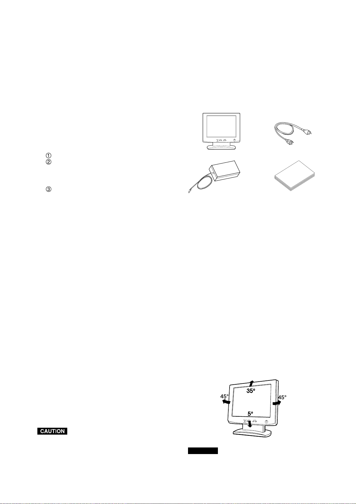
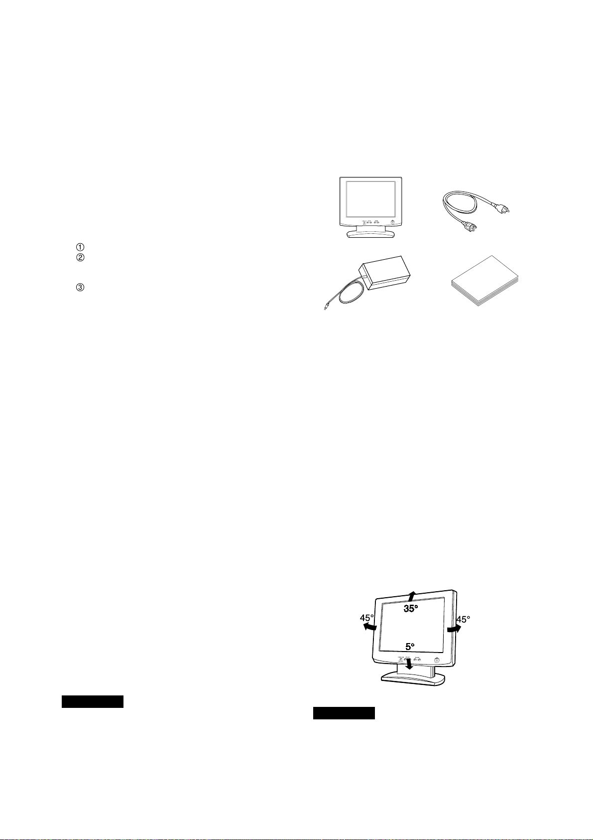
Figure 2
Keep your fingers away from the pivot area of the tilt/swivel
base.
CAUTION
1.13 Unpacking
After you unpack the box you should have all of the items
indicated in Figure 1. Save the box and packing materials
in case you ship or transport the monitor.
Figure 1
1
2
3
4
1. Multisync
®
LCD1800
™
Monitor
2. Power Cord
3. AC-Adapter
4. User’s Guide (this booklet)
1.14 Tilt Base
The monitor comes with a tilt base. This enables you to
position the monitor to the best angle for maximum viewing
comfort.
Screen Position Adjustment
Adjust the tilt of the monitor by placing your hands at
opposite sides of the case. You can adjust the monitor as
shown in Figure 2.
1.11 Location Considerations
When setting up and using the monitor, keep the following
in mind:
• For optimum viewing, avoid placing the monitor against
a bright background or where sunlight or other light
sources may reflect on the display area of the monitor;
place the monitor just below eye level.
• Avoid covering the slots or openings of the monitor.
Allow adequate ventilation around the monitor so the
heat from the monitor can properly dissipate. Avoid
putting the monitor into any enclosure that does not
have adequate ventilation.
• Avoid exposing the monitor to rain, excessive mois-
ture, or dust, as this can cause a fire or shock hazard.
• Avoid placing the monitor, or any other heavy object,
on the power cord. Damage to the power cord can
cause a fire or electrical shock.
• When transporting the monitor, handle it with care.
• Avoid giving any shock or scratch to the screen, as the
screen is fragile.
1.12 Cleaning Your Monitor
When clean the monitor, please follow these guidelines:
• Always unplug the monitor before cleaning.
• Wipe the screen and cabinet front and sides with a soft
cloth.
• Do not spray directly on the screen as excess cleaner
may drip into the monitor causing a damage.
Do not use benzene, thinner or any volatile substances to
clean the unit as the finish may be permanently marked.
Never leave the monitor in contact with rubber or vinyl for
an extended time period.e the monitor in contact with
rubber or vinyl for an extended time period.
1.10 AccuColor
®
Control Function
The following color modes are available:
1. sRGB: sRGB mode dramatically improves the color
fidelity in the desktop environment by a single stan-
dard RGB color space. With this color supported
environment, the operator could easily and confi-
dently communicates color without further color man-
agement overhead in the most common situations.
We recommend you set the monitor to "Graphics"
mode. (Unadjustable.)
2. VIDEO: Suitable for motion picture. (Unadjustable.)
3. NATIVE: Original color presented by the LCD panel.
(Unadjustable.)
4. CUSTOM: The following items are adjustable.
COLOR TEMPERATURE: 5000K~9600K
COLOR CONTROL: This function enables inde-
pendent adjustment of 6 color (Red, Yellow, Green,
Cyan, Blue and Magenta) elements and color
saturation.
COLOR RESET: To restore to the color tempera-
ture and color control to the factory preset.
-
+
-
+
- 1-5 -
ENGLISH
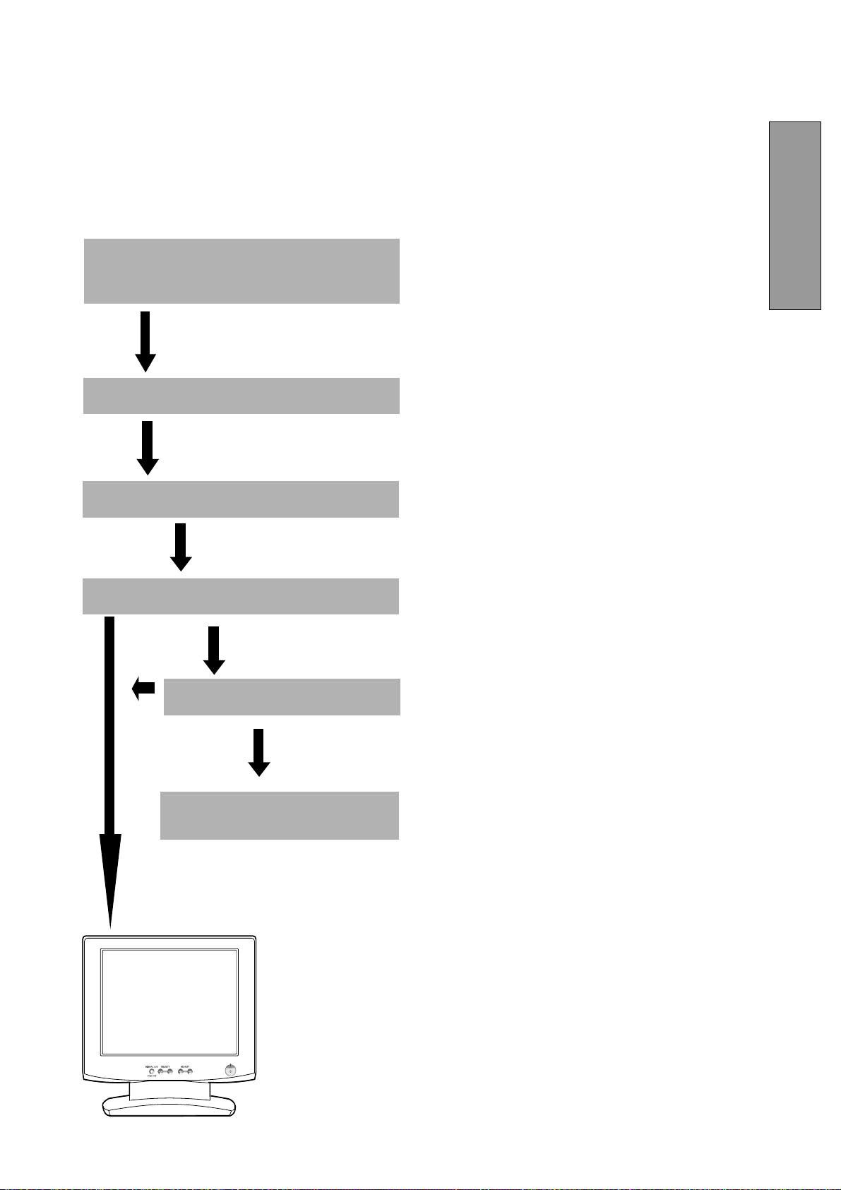
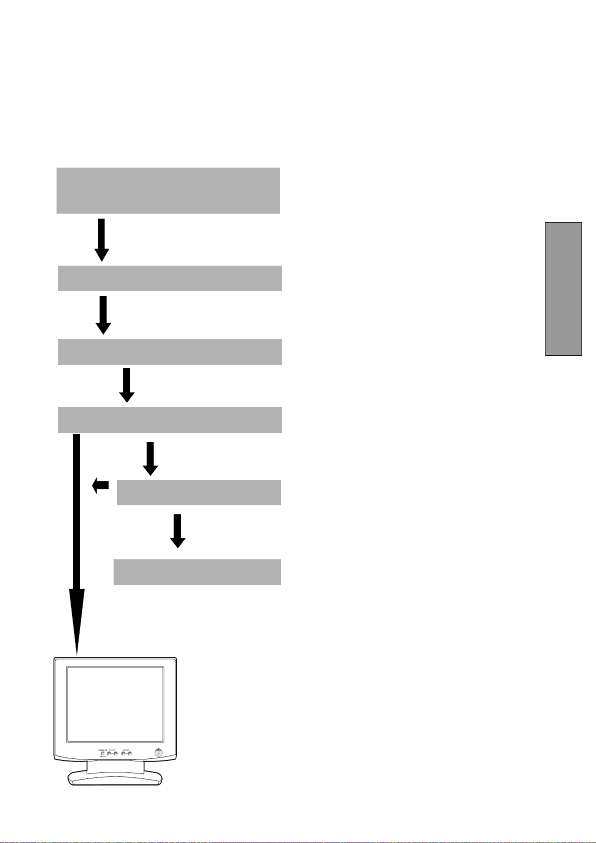
Turn on the computer.
Turn on the monitor.
If a problem appears.
If the problem persists.
Call for your authorized Product
Support.
See 6. TROUBLESHOOTING
OK
OK
1.15 Quick Operation Chart
To summarize the steps in connecting your computer and
adapter with MultiSync LCD1800
™
color LCD monitor and
setting the necessary controls and switches, refer to the
chart below.
Connect the power cord to the MultiSync LCD1800
color LCD monitor and the signal cable between
the MultiSync LCD1800 and the computer.
Set the controls and switches.
-
+
- 1-6 -
SIGNAL A/B SELECT ADJUST
-
+
OSD OFF
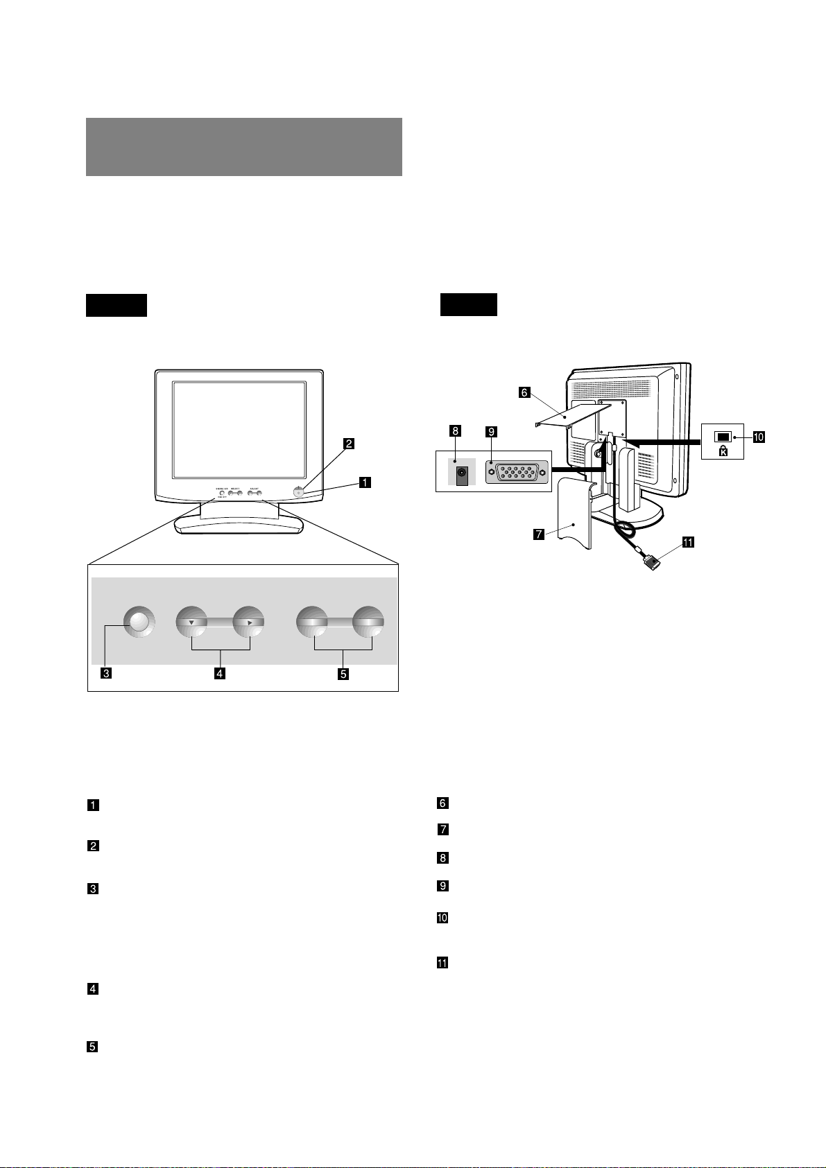
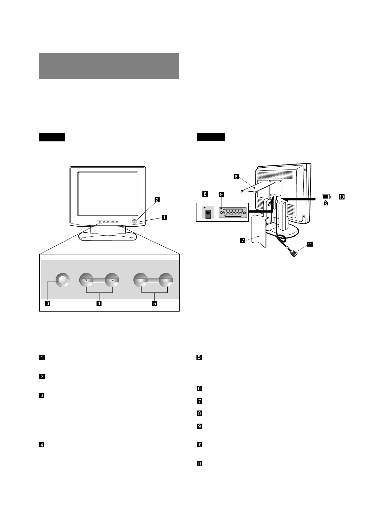
2.1 Control Names
See Figures 3 and 4 for the location of the user controls,
indicator and connectors.
Each part is identified by number and described
individually.
Figure 3
REAR
Figure 4
FRONT
2.2 Function
POWER SWITCH: A push-on / push-off switch for
power input.
POWER-ON INDICATOR: This indicator illumi-
nates when power is on.
SIGNAL A/B and OSD OFF BUTTON: This button
has two functions, as follows.
Under the OSM off condition: Push to select the
signal input connector which is connected to the
computer which you want to use.
Under the OSM on condition: Push to turn off OSM.
FUNCTION SELECT BUTTONS: Push the select
buttons to choose one of the functions that is
superimposed on the display screen.
FUNCTION ADJUST BUTTONS: Push the adjust
buttons to adjust the image on the screen that is
selected via the function select buttons.
CABLE COVER (UPPER)
CABLE COVER (LOWER)
DC POWER CONNECTOR
SIGNAL INPUT CONNECTOR (SIGNAL B)
BURGLARPROOF KEY LOCK HOLE: available
for KENSINGTON
®
MicroSaver Security System.
SIGNAL CABLE (SIGNAL A)
-
+
2
2 PART NAME
- 1-7 -
ENGLISH
Signal Cable
High Resolution
Graphic Video Card
Figure 5
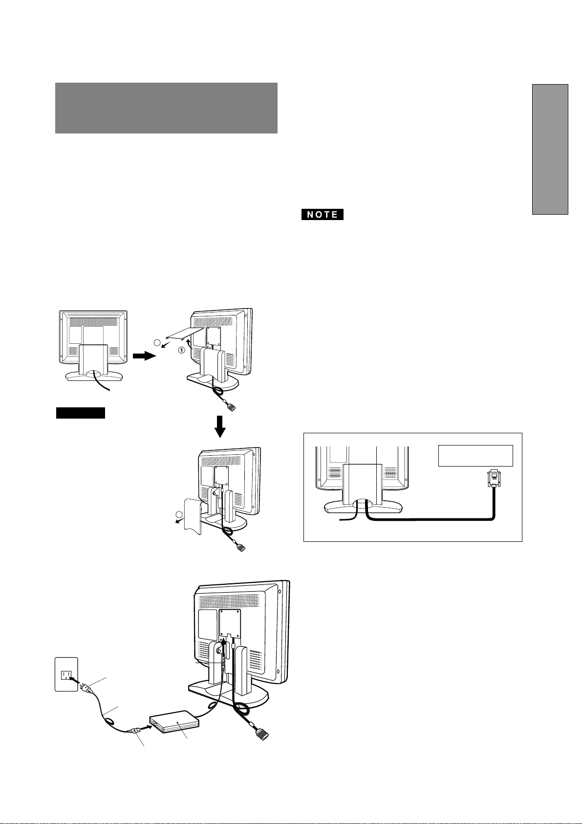
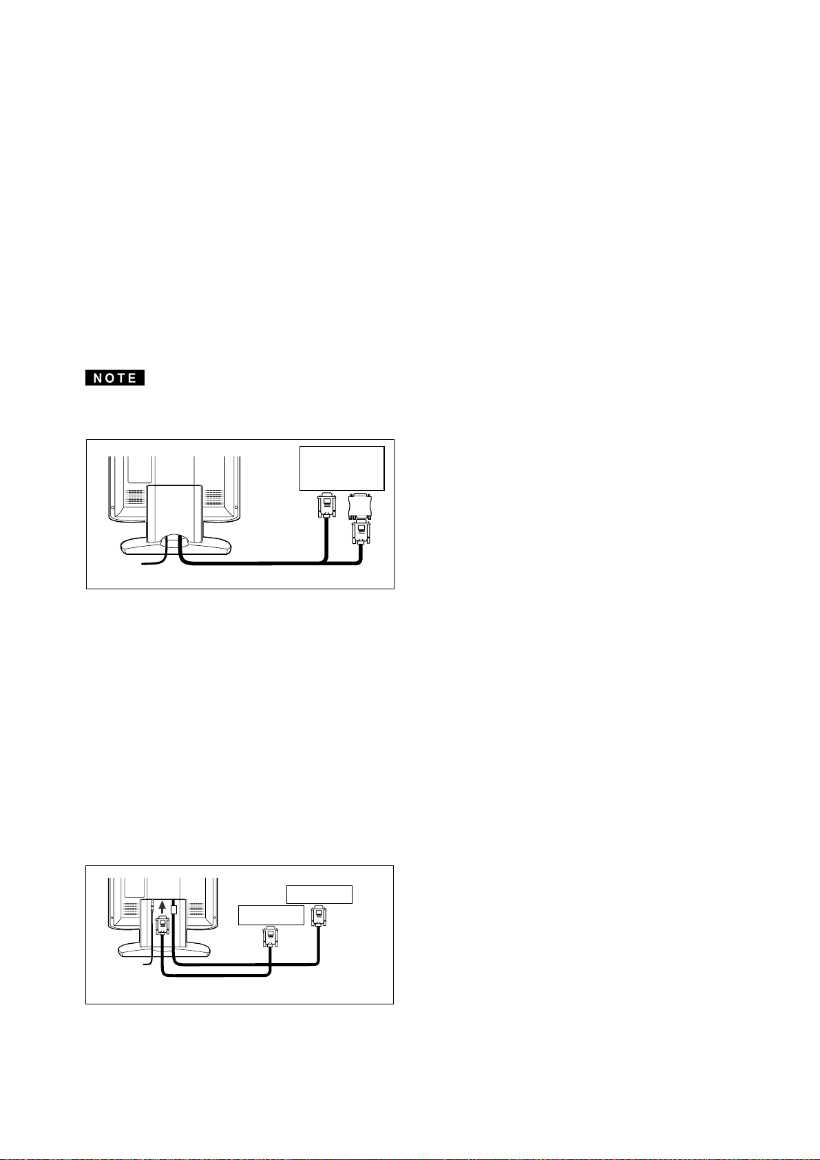
3.2 Signal Cable Connection
The attached video signal cable provides a D-SUB-15P
connector for the VGA compatible analog RGB outputs on
your computer. Apple Macintosh Computers can also be
interfaced using the optional Macintosh adapter.
• The Sync-On-Green signal involving equalizing pulse
is not applicable to the monitor.
• Don't input the Sync-On-Green signal and separate
sync signal to the monitor at the same time. It may
make the screen abnormal.
3.2.1 Connecting to Any IBM VGA Compatible Sys-
tem
Figure 5 shows the signal cable connection to the Video
Graphics Array (VGA) port in an IBM Personal System/2
®
or any VGA compatible system.
1. Power off, the monitor and the computer.
2. Connect the one end of the signal cable to the 15-pin
connector on the VGA controller card.
3. Power on the monitor, then the computer.
4. After using the system, power off the monitor, then the
computer.
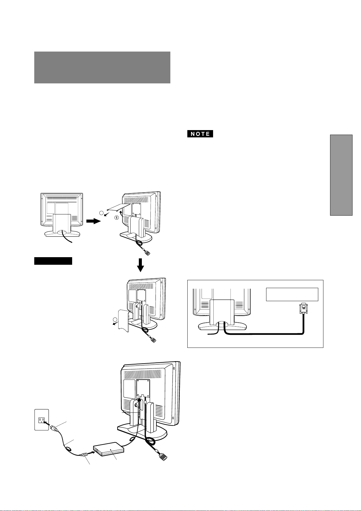
On the back of the monitor are three plug-in connec-
tions: one for the DC power connection and others for
the video signal connection.
3.1 AC Power Connection
Remove the cable covers. The DC jack from the AC
Adapter is connected into the DC power connector on the
back of the monitor. One end of the power cord is
connected into the AC Adapter, and another end of the
power cord is plugged into a AC outlet. The monitor’s auto-
sensing AC Adapter can automatically follow the AC input.
The socket-outlet shall be
installed near the equipment
and shall be easily acces-
sible. During servicing, dis-
connect the plug from the
socket-outlet.
Do not use this AC Adapter
to other equipments, as this
can cause a fire.
When operating the LCD
monitor with its AC220-240V
worldwide power supply,use
a power supply cord that
matches the power supply
voltage of the AC power
outlet being used.The power
supply cord you use must
have been approved by and
comply with the safety stan-
dards of your country.
Plug
CAUTION
Power Cord
Receptacle
AC Adapter
DC Jack
<How to remove the covers>
3
2
3
3
INSTALLATION AND
CONNECTION
- 1-8 -
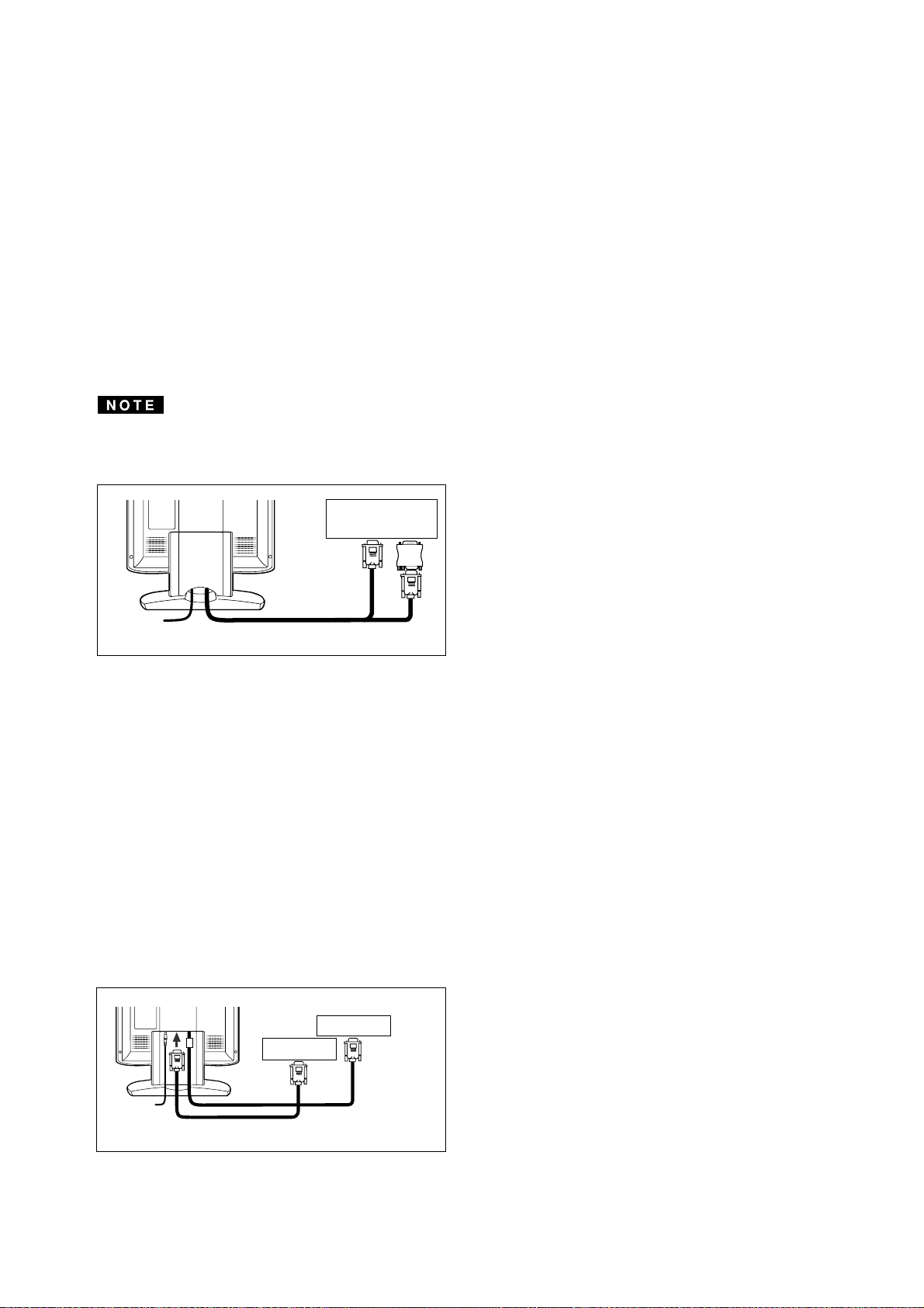
3.2.3 Connecting to Two Computers
Figure 7 shows the signal cable connection to two com-
puters.
1. Power off, the monitor and the computers.
2. Connect the one end of the equipped signal cable to
the 15-pin connector on a computer.
3. Prepare signal cable. (For the signal cable, contact
your dealer.)
Connect the D-SUB-15P male connector of the sig-
nal cable to the 15-pin connector on the monitor and
other end to the computer.
4. Power on the monitor, then the computers.
5. After using the system, power off the monitor, then
the computers.
Computer
D-SUB-15P
D-SUB-15P
Signal Cable
Figure 7
Computer
Apple Macintosh
Computer
Signal Cable
3.2.2 Connecting to An Apple Macintosh Computer
Figure 6 shows the signal cable and Macintosh Adapter to
the video port in an Apple Macintosh.
1. Power off, both the monitor and the computer.
2. Connect the 15-pin (D-SUB-15P) end of the Macintosh
Adapter to the straight 15-pin connector on the
Macintosh video port on the computer or on the video
board.
3. Connect the sub-miniature 15-pin (D-SUB-15P) end
of the Macintosh Adapter to the signal cable.
4. Power on the monitor, then the Macintosh.
5. After using the system, power off the monitor, then the
Macintosh.
For the Apple Macintosh Computers having a VGA com-
patible port, steps 2 through 4 are not necessary. Connect
the one end of the signal cable to the port directly.
Figure 6
Macintosh Adapter
- 1-9 -
ENGLISH
-
+
-
+
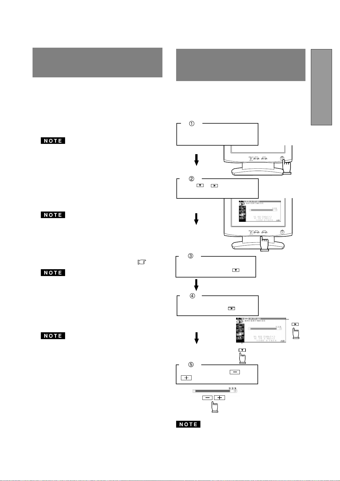
Adjust by pressing or
button.
Select the item icon on Sub
Menu by pressing button.
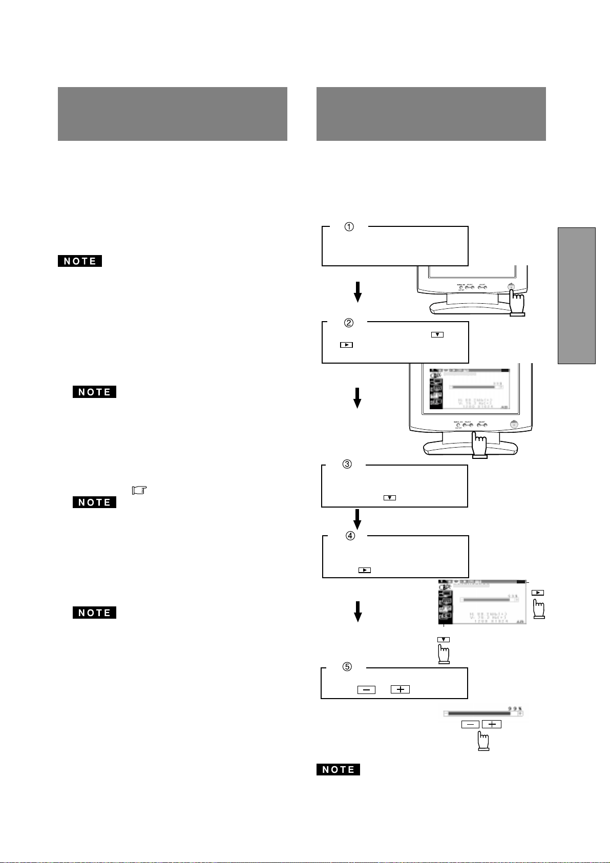
Turn on the monitor.
Press or to display the
OSM screen.
Select the group icon on Main
Menu by pressing .
Sub Menu
Main Menu
The monitor has an OSM (On Screen Manager) function.
The following procedure shows how to adjust the screen
with using the OSM function.
How to Adjust the Screen
If you don't press any button for approximately 30 sec-
onds, the OSM screen will disappear. Or press OSD OFF
button, then the OSM screen will disappear quickly.
Two methods, "AUTO SETUP" and "OSM
™
Adjustment"
are available for adjusting the screen. (For the "OSM
Adjustment", see 5. OSM (On Screen Manager) FUNC-
TIONS.) Conduct the "AUTO SETUP" first. And then, do
the "OSM Adjustment" if necessary.
The “AUTO SETUP” is to adjust "CONTRAST", "HORI-
ZONTAL POSITION", "VERTICAL POSITION", "CLOCK",
"CLOCK-PHASE" and "BLACK LEVEL" automatically.
• "AUTO SETUP" function may not work well with some
computer. In the case, conduct the "OSM Adjustment".
• In case that the monitor is used with an interlace signal
of resolution 1280 dots by 1024 lines, one line in the top
or bottom of the screen is lost. This condition can not
be corrected by any adjustment.
Conduct the "AUTO SETUP" according to the following
procedure:
1. Turn on the computer and monitor.
If you don't recognize the icon on the screen, adjust
“CLOCK” until you can, with using the "OSM Function".
If you don't see the icon because of the screen shifted
to vertical or horizontal direction, adjust "VERTICAL
POSITION" or "HORIZONTAL POSITION" until you
can, with using the "OSM Function".
2. Select "AUTO SETUP" at the OSM menu.( P1-10)
In case that the screen area has a black back ground
like "MS-DOS PROMPT", the "AUTO SETUP" may not
work well.
3. Press "+" button. Then, the "AUTO SETUP" start.
During the "AUTO SETUP", "AUTO SETUP" is dis-
played on the screen and when it finishes, "AUTO
SETUP" disappear from the screen. "AUTO SETUP"
takes approx. 10 secs to finish.
In case that the monitor is used with an interlace signal,
one line in the top or bottom of the screen is lost as a
result of the "AUTO SETUP". In the case, adjust the
"VERTICAL POSITION" by the "OSM Adjustment".
4
4
AUTO SETUP
FUNCTION
5
5
OSM(On Screen Man-
ager) FUNCTIONS
- 1-10 -
Press and buttons together, to restore to the factory preset level.
Press "ALL RESET" to restore to the factory preset level.
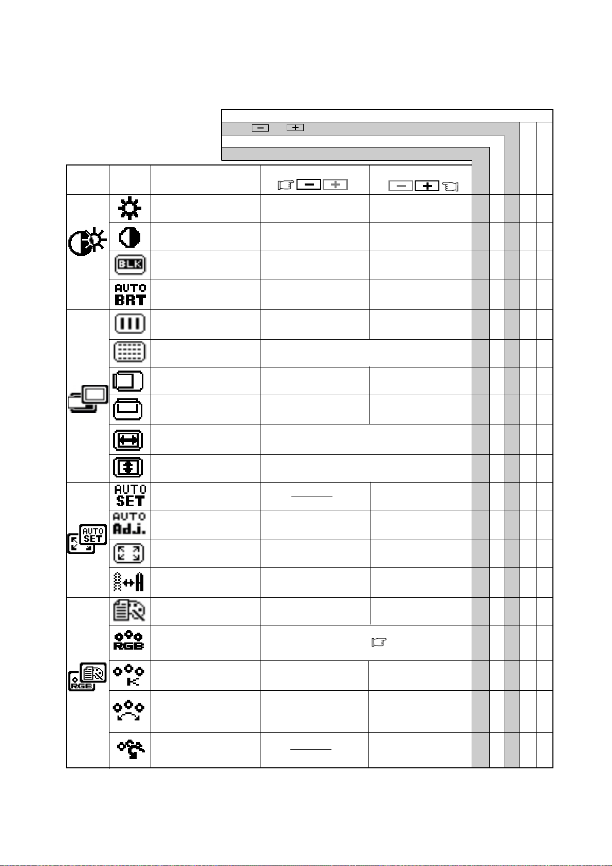
To be deep of black
color.
To be light of black
color.
To move the image to
the left.
To move the image
to the right.
To move the image
down.
To move the image
up.
To display by TEXT
mode.
To restore to the color tem-
perature and color control to
the factory preset.
To adjust the height of the image on the screen.
To adjust the width of the image on the screen.
Group
Icon
Press the Minus Button: Press the Plus Button:
Item
Icon
Item
To decrease the
brightness.
To increase the
brightness.
To decrease the con-
trast.
To increase the con-
trast.
To display by GRAPHIC
mode.
Set data by each timing.
Set data does not change by the changing of the signal timing.
To conduct Auto Setup.
To off the Auto Bright
Function.
To on the Auto Bright
Function.
To narrow the width of
the image on the screen
to the left.
To change the snow noise of the image.
To expand the width
of the image on the
screen to the right.
5.1 Adjustment Items
To decrease the color
temperature.
To increase the color
temperature.
To off the Auto Adjust-
ment Function.
To on the Auto Adjust-
ment Function.
Factory Presets
User Presets
Select the desired Color from sRGB, VIDEO
NATIVE and CUSTOM. ( P1-4)
(sRGB, VIDEO, NATIVE: Unadjustable.)
To decrease the
distinction.
To increase the
distinction.
The color of screen is
adjusted to the "-"
symbol's color at Level-
bar's left side.
The color of screen is
adjusted to the "+"
symbol's color at Level-
bar's right side.
To set the normal screen
area.
To set the expanded
screen area.
BRIGHTNESS ○○○○
CONTRAST ○○○○
BLACK LEVEL ○○○○
AUTO BRIGHTNESS ○○○
CLOCK ○○
CLOCK PHASE ○○
HORIZONTAL POSITION
○○
VERTICAL POSITION ○○
H RESOLUTION ○○
V RESOLUTION ○○
AUTO SETUP ‑ ‑ ‑‑‑
AUTO ADJUST ○○
EXPAND ○○
SHARPNESS ○○○
DISPLAY MODE ○○○
COLOR ○○○
COLOR TEMPERATURE
○○○○
COLOR CONTROL ○○○○
COLOR RESET ‑ ‑ ‑‑‑
- 1-11 -
ENGLISH
To choose the language used on OSM.
ENG...English, DEU...German, ESP...Spanish,
FRA...French, ITA...Italian, JPN...Japanese
To select the constant
power mode.
To select the power
save mode.
To restore to the fac-
tory preset mode.
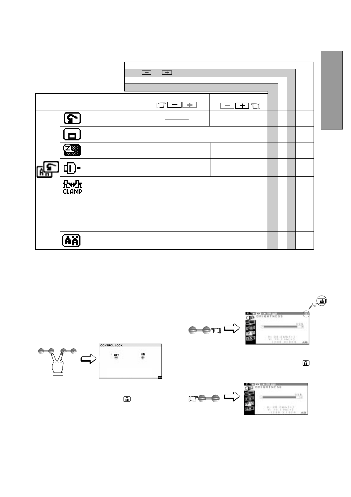
1. Press the right of select button and minus of adjust
button together, the "CONTROL LOCK" screen ap-
pears.
2. Press the plus button to lock on the OSM
TM
. During
the Locked condition, "Key mark " is indicated
on the upper-right of the OSM screen and "BRIGHT-
NESS" is only adjustable.
A/B signal change and OSD OFF by front SW are
functionable.
3. Press the minus button to lock off the OSM, and if you
press any select or adjust button, Key mark
is
disappeared from the OSD screen. You can operate
OSM, again.
5.2 CONTROL LOCK Mode Operation
ADJUST
-
+
ADJUST
-
+
SELECT
ADJUST
Press and buttons together, to restore to the factory preset level.
Press "ALL RESET" to restore to the factory preset level.
Group
Icon
Press the Minus Button:
Press the Plus Button:
Item
Icon
Item
Set data by each timing.
Set data does not change by the changing of the signal timing.
Factory Presets
User Presets
ALL RESET ‑‑‑‑‑
OSD POSITION ○○○
POWER SAVE ○○○
AUTO SELECT ○○○
CLAMP PULSE POSITION
○○○
LANGUAGE ○
To eliminate an excessive green or white-back
ground that may occur when both Sync-On-Green
and external sync signals are applied to the moni-
tor.
To clamp the video sig-
nal at the front of the H-
Sync pulse.
To clamp the video sig-
nal at the back of the H-
Sync pulse. If you con-
nect to an older
Macintosh, you may
need to press plus but-
ton.
To off the Auto Adjust-
ment Function.
To on the Auto Select
Function.
To move the OSD position for 5 places.
- 1-12 -
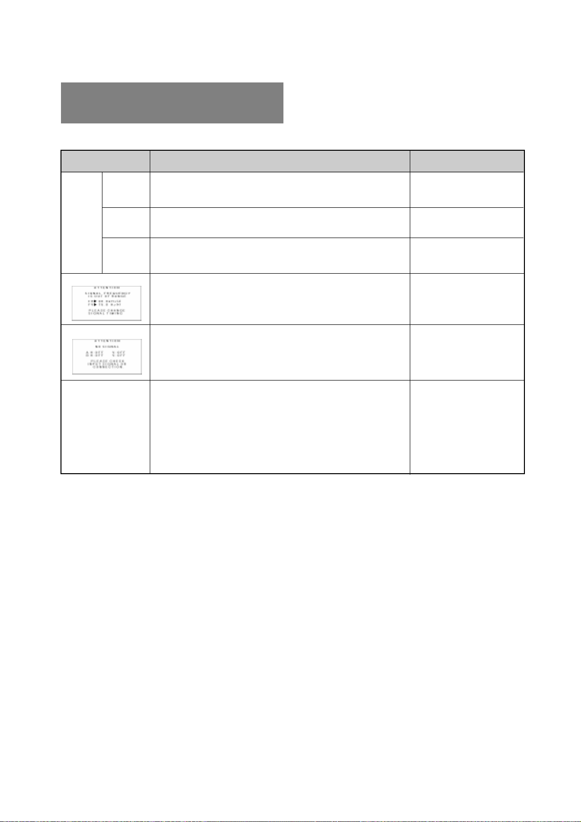
PROBLEM
ITEMS TO CHECK
Before calling your Authorized Product Support, please
check that the items below are properly connected or set.
In case of using a non-standard signal, please check the
pin assignments and the signal timing of your computer
with the specification outlined in 7. SPECIFICATIONS.
LOCATION
•
•
•
•
•
•
•
•
•
•
•
•
•
•
•
•
•
•
•
•
•
•
•
•
Front
Front
Rear
Rear
Computer
Check the specification
of graphics adapter and
monitor
Rear
Computer
Front (OSM
™
)
Front (OSM)
Contrast and brightness controls.
Power switch.
Power cord disconnected.
Signal cable disconnected.
Computer power switch.
Power management function is active.
Input signal frequency range is out of specification.
Display Resolution is out of range.
Signal cable disconnected.
Computer power switch.
Power management function is active.
Adjust, RESOLUTION, CLOCK, CLOCK-PHASE, H-POSITION,
and V-POSITION with non-standard signals.
Monitor may not be able to get full-screen image depending on
signal. In this case, please select other resolution, or other
vertical refresh timing.
Make sure you wait a few seconds after adjusting the size of the
image before changing or disconnecting the signal or powering
OFF the monitor.
LED On
(Green)
LED Off
LED On
(Amber)
No
picture
Illegible image, ab-
normal position of
screen, or too small
or too large of a dis-
play size
The following message appeared.
The following message appeared.
6
6
TROUBLESHOOTING
- 1-13 -
ENGLISH
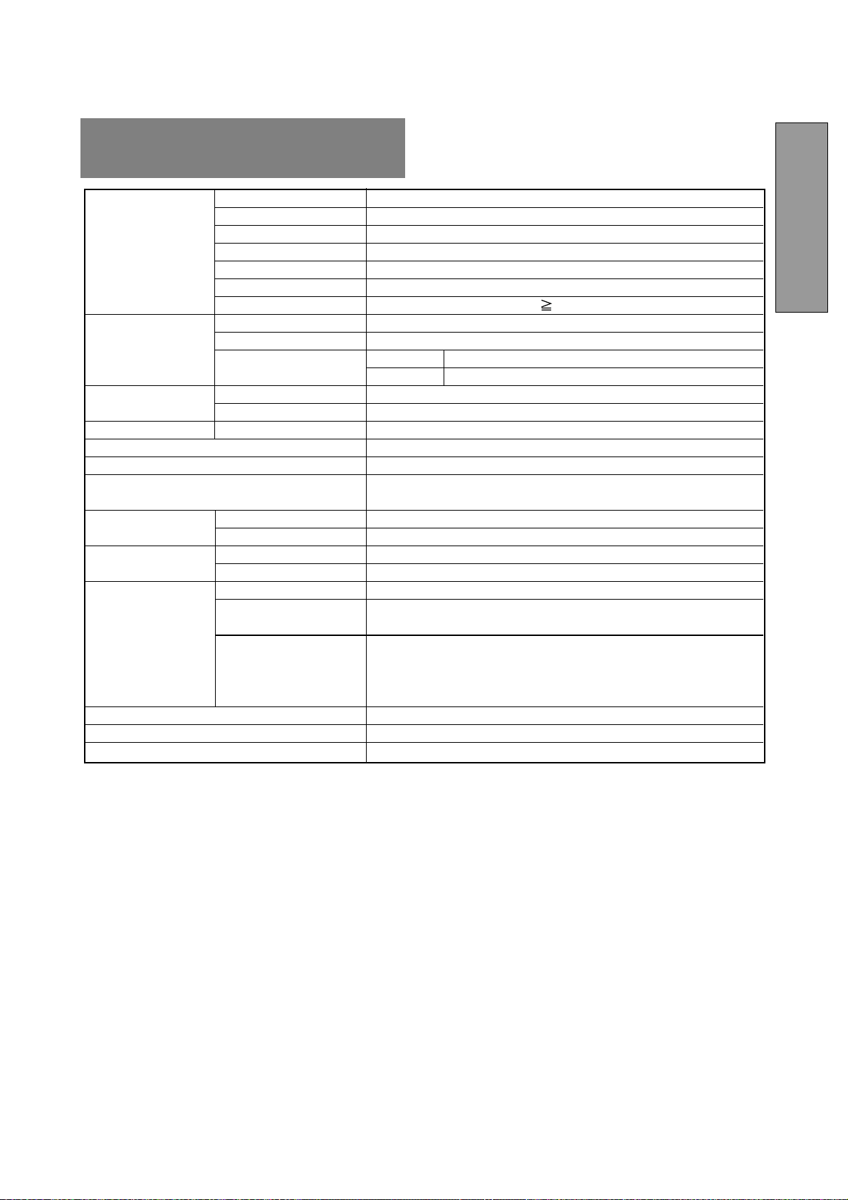
LCD Panel 46cm/18.1" Color TFT Panel
Type Active Matrix
Resolution 1280 dots x 1024 lines
Pixel Pitch 0.28mm
Color Filter R, G, B vertical stripe type
Face Finishing Anti-glare, Hard Coated
Viewing Angle ±80°(Horizontal/Vertical) CR 5
Video 0.7Vp-p analog RGB
Sync Sync.on Green or Separated H,V or Composite sync.
Input Impedance Video 75 Ω
Sync 2.2k Ω
SCANNING Horizontal 24.0 - 80.0kHz
FREQUENCY Vertical 50.0 - 86.0Hz
DISPLAY SIZE H x V 359mm x 287.2mm
NUMBER OF COLOR 16.77 Million Colors
BRIGHTNESS(with standard full white video signal) 200 cd/m
2
(Typ.)
SIGNAL INPUT CONNECTORS D-SUB-15P (One is with the detachable signal cable, and another is
behind the cable cover.
OPERATING Temperature 5 ‑ 35°C
ENVIRONMENT Humidity 10 ‑ 90%RH (without condensation)
POWER SOURCE Display Monitor 55W MAX
AC-Adapter INPUT: AC100~240V±10%, 50/60Hz OUTPUT: DC15V
Safety UL1950 (UL), CSA C22.2 No.950 (C-UL), EN60950(TÜV-GS)
EMC FCC Class-B, DOC Class-B, EN55022 Class-B, EN50082-1
VCCI Class-B, EN61000-3-3
REGULATIONS Other CE-Marking, MPR-II,TCO '99,
ISO 9241-3, ISO 9241-7, ISO 9241-8(TÜV-GS)
International E
NERGY STAR
Energy 2000 Labeling Award
(W)18.1" x (H)18.9" x (D)8.7"/ (W)460mm x (H)481mm x (D)220mm
8.2kg (18.1lbs.)(without AC Adapter and cables)
TILT BASE -5° ~ +35° Tilt Angle ±45° Swivel Angle
CABINET
LCD MODULE
INPUT SIGNAL
WEIGHT
7
7
SPECIFICATIONS

- 1-14 -
NEC-Mitsubishi (hereinafter “NEC-MITSUBISHI”), warrants
this Product to be free from defects in material and work-
manship and, subject to the conditions set forth below,
agrees to repair or replace (at NEC-MITSUBISHI’s sole
option) any part of the enclosed unit which proves defective
for a period of three (3) years from the date of first
consumer purchase. Spare parts are warranted for ninety
(90) days. Replacement parts or units may be new or
refurbished and will meet specifications of the original
parts or unit.
This warranty gives you specific legal rights and you may
also have other rights which vary from state to state. This
warranty is limited to the original purchaser of the Product
and is not transferable. This warranty covers only NEC-
MITSUBISHI-supplied components. Service required as a
result of third party components is not covered under this
warranty. In order to be covered under this warranty, the
Product must have been purchased in the U.S.A. or Canada
by the original purchaser. This warranty only covers Prod-
uct distribution in the U.S.A. or Canada by NEC-
MITSUBISHI. No warranty service is provided outside of
the U.S.A. or Canada. Proof of Purchase will be required by
NEC-MITSUBISHI to substantiate date of purchase. Such
proof of purchase must be an original bill of sale or receipt
containing name and address of seller, purchaser, and the
serial number of the product.
It shall be your obligation and expense to have the Product
shipped, freight prepaid, or delivered to the authorized
reseller from whom it was purchased or other facility
authorized by NEC-MITSUBISHI to render the services
provided hereunder in either the original package or a
similar package affording an equal degree of protection. All
Products returned to NEC-MITSUBISHI for service MUST
have prior approval, which may be obtained by calling 1-
800-632-4662.
The Product shall not have been previously altered, re-
paired, or serviced by anyone other than a service facility
authorized by NEC-MITSUBISHI to render such service,
the serial number of the product shall not have been altered
or removed. In order to be covered by this warranty the
Product shall not have been subjected to displaying of
fixed images for long periods of time resulting in image
persistence (afterimage effects), accident, misuse or abuse
or operated contrary to the instructions contained in the
User’s Manual. Any such conditions will void this warranty.
NEC-MITSUBISHI SHALL NOT BE LIABLE FOR DIRECT,
INDIRECT, INCIDENTAL, CONSEQUENTIAL, OR OTHER
TYPES OF DAMAGES RESULTING FROM THE USE OF
ANY NEC-MITSUBISHI PRODUCT OTHER THAN THE
LIABILITY STATED ABOVE. THESE WARRANTIES ARE
IN LIEU OF ALL OTHER WARRANTIES EXPRESS OR
IMPLIED, INCLUDING, BUT NOT LIMITED TO, THE IM-
PLIED WARRANTIES OF MERCHANTABILITY OR FIT-
NESS FOR A PARTICULAR PURPOSE. SOME STATES
DO NOT ALLOW THE EXCLUSION OF IMPLIED WAR-
RANTIES OR THE LIMITATION OR EXCLUSION OF
LIABILITY FOR INCIDENTAL OR CONSEQUENTIAL
DAMAGES SO THE ABOVE EXCLUSIONS OR LIMITA-
TIONS MAY NOT APPLY TO YOU.
This Product is warranted in accordance with the terms of
this limited warranty. Consumers are cautioned that Prod-
uct performance is affected by system configuration, soft-
ware, the application, customer data, and operator control
of the system, among other factors. While NEC-MITSUBISHI
Products are considered to be compatible with many
systems, specific functional implementation by the
customers of the Product may vary. Therefore, suitability of
a Product for a specific purpose or application must be
determined by consumer and is not warranted by NEC-
MITSUBISHI.
For the name of your nearest authorized NEC-MITSUBISHI
service facility, contact NEC-MITSUBISHI at 1-800-632-
4662.
LIMITED WARRANTY
- 2-1 -
FRANÇAIS
ATTENTION !
Ne pas retirer le boîtier du moniteur : vous pouvez
être exposé à des tensions élevées et à d’autres
risques.
Marques déposées
IBM, PC, PS/2, PS/V, Personal System/2 sont des marques
déposes d’International Business Machines Corp.
Apple Macintosh est une marque déposée de Apple Com-
puter Inc.
Quadra est une marque déposée de Apple Computer Inc.
UNIX est une marque déposée aux Etats Unis et dans
d’autres pays, la licence reste la propriété exclusive de X/
open Company limited.
E
NERGY
S
TAR
est une marque déposée aux Etats Unis.
NEC est une marque déposée de NEC Corporation.
Toutes les autres marques de commerce et marques déposées
sont la proriété de leurs détenteurs respectifs.
© 2000 NEC-MITSUBISHI Electronics Display of America, Inc.
DÉCLARATION DE CONFORMITÉ POUR
MARQUAGE CE:
Nous, NEC-MITSUBISHI ELECTRIC VISUAL
SYSTEMS CORPORATION déclarons sous nolre
seule responsabililé que le produit auquel se rétére
celte déclaration est conforme a la aux normes ou
autres documents normatifs:
EN60950
EN55022 Classe B
EN50082-1
EN61000-3-3
conformément aux dispositions de Directives:
73/23/EEC Lage-netspanningsrichtlijn
89/336/EEC EMC-richtlijn
ATTENTION!
Ce produit n'a pas été désigné pour fonctionner dans
des systèmes qui permettent de mesurer, d’évaluer ou
d’assurer le bon fonctionnement des fonctions du
corps humain. NEC-MITSUBISHI ELECTRIC VISUAL
SYSTEMS CORPORATION ne peut en aucun cas être
tenu responsable en cas d’utilisation de ce produit sur
de tels systèmes.
TABLE DES MATIERES
1. INTRODUCTION................................................ 2-2
1.1 Caractéristiques.................................... 2-2
1.2 Valeurs préréglées stockées en
mémoire................................................ 2-2
1.3 IPM
MC
(Intelligent Power Manager)
System.................................................. 2-3
1.4 DDC ...................................................... 2-3
1.5 Sélection du mode d’affichage ............. 2-3
1.6 Fonction d’autoréglage ......................... 2-3
1.7 Fonction expansion automatique
de l’image ............................................. 2-3
1.8 Connecteur du signal d’entrée pour la
commande de sélection automatique... 2-3
1.9 Fonction luminosité automatique.......... 2-3
1.10 AccuColor
®
Control System.................. 2-4
1.11 Considérations relatives à
l’emplacement du moniteur ................. 2-4
1.12 Nettoyage de votre moniteur ................ 2-4
1.13 Déballage ............................................. 2-4
1.14 Socle pivotant et inclinable................... 2-4
Réglage de la position de l’écran ......... 2-4
1.15 Processus de mise en route ................. 2-5
2. GLOSSAIRE....................................................... 2-6
2.1 Dénomination ....................................... 2-6
2.2 Fonction des Commandes.................... 2-6
3. INSTALLATION ET CONNEXION ..................... 2-7
3.1 Branchement au secteur ...................... 2-7
3.2 Branchement des câbles véhiculant
les signaux........................................... 2-7
3.2.1 Branchement à tout système
compatible IBM VGA....................... 2-7
3.2.2 Raccordement à un Apple Macintosh
Ordinateur ....................................... 2-8
3.2.3 Connexion de 2 unités centrales .... 2-8
4. FONCTION REGLAGE AUTOMATIQUE ........... 2-9
5. UTILISATION DES FONCTIONS....................... 2-9
5.1 Différents réglages ............................... 2-10
5.2 Mode VERROUILLAGE........................ 2-11
6. DEPANNAGE..................................................... 2-12
7. SPÉCIFICATIONS ............................................. 2-13
GARANTIE LIMITÉE................................................ 2-14
- 2-2 -
1
Nous vous adressons nos félicitations pour votre achat
d’un moniteur LCD couleur haute résolution MultiSync
LCD1800
MC
. Ce guide vous permet de connecter et d’utiliser
votre moniteur MultiSync LCD1800 en toute sécurité.
Vous y trouverez également les spécifications techniques
et les instructions nécessaires pour résoudre certains
problèmes que vous pourriez rencontrer lors de l’utilisation
de votre MultiSync LCD1800.
1.1 Caractéristiques
Le MultiSync LCD1800 (46cm/18,1"), sont des moniteurs
LCD intégrant un microprocesseur compatibles avec la
plupart des standards graphiques RVB (Rouge, vert,
bleu).
Cette fonction procure des caractères nets et des couleurs
éclatantes avec une utilisation PC ou Macintosh.
Entrées doubles
Équipé d’entrées doubles, vous permettant de
raccorder le moniteur à deux systèmes. Vous pouvez
facilement commuter entre les ordinateurs par une
pression sur un bouton de réglage du panneau de
commande avant.
Encombrement réduit
Constitue la solution idéale pour les environnements
qui nécessitent une image de haute qualité et un
encombrement et un poids limité.
L’encombrement réduit et le faible poids du moniteur
permettent de le déplacer ou de le transporter
rapidement d’un point à un autre.
AccuColor
®
Control System
Vous permet de régler les couleurs sur l’écran et de
définir la précision des couleurs de votre moniteur
suivant toute une gamme de standards.
Réglages OSM
MC
(On-Screen Manager)
Vous permettent de régler rapidement et facilement
tous les éléments de votre image écran à l’aide de
menus simples à utiliser.
Caractéristiques ErgoDesign
®
L’ergonomie est poussée pour améliorer
l’environnement de travail, protéger la santé de
l’utilisateur et induire des économies. Le concept
ErgoDesign se traduit par les différents contrôles de
l’OSM pour un réglage rapide et facile de l’image, une
base inclinable pour une configuration de l’angle de
vision, une embase réduite et une conformité aux
normes MPR2 et les recommandations TCO en ce qui
concerne les émissions basse fréquences.
Plug and Play
La solution Microsoft
®
avec le système d’exploitation
Windows
®
facilite la configuration et l’installation en
permettant au moniteur d’envoyer directement ses
caractéristiques (comme la taille de l’écran et les
résolutions supportées) à votre ordinateur, optimisant
ainsi automatiquement les performances de l’affichage.
Système IPM
MC
(Intelligent Power Manager)
Fournit des méthodes innovantes d’économie
d’énergie qui permettent au moniteur de passer dans
un mode à faible consommation électrique lorsqu’il est
sous tension sans être utilisé, ce qui économise les
deux tiers du coût de la consommation électrique du
moniteur, réduit les émissions et diminue le coût de la
climatisation de la salle.
1 INTRODUCTION
Technologie multifréquences
Règle automatiquement le moniteur sur la fréquence
de balayage de la carte vidéo, ce qui procure un
affichage à la résolution requise.
Caractéristique FullScan
MC
Vous permet d’utiliser toute la surface de l’écran avec
la plupart des résolutions, ce qui agrandit l’image de
façon significative.
Interface de fixation au Standard Vesa
Permet à l’utilisateur de raccorder son moniteur
MultiSync à n’importe quel autre bras ou baie de
montage à Standard VESA. Permet de monter le
moniteur sur un mur ou un bras à l’aide de n’importe
quel autre dispositif compatible.
XtraView
®
Permet à l’utilisateur d’observer le moniteur à partir de
n’importe quel angle (160 degrés). Offre des angles de
vision complets de 160° haut, bas, gauche ou droit.
1.2 Valeurs préréglées stockées en mémoire
Pour limiter autant que possible la nécessité d’effectuer
des réglages, les standards d’affichage les plus courants
ont été chargés en usine dans la mémoire du moniteur,
comme le montre le Tableau 1. Dès que l’un de ces
standards se trouve détecté, le centrage et la dimension
de l’image sont réglés automatiquement. Toutes les valeurs
préréglées en usine peuvent être modifiées au moyen des
commandes accessibles à l’utilisateur. Ce moniteur peut
stocker jusqu’à 7 standards d’affichage supplémentaires.
Les nouvelles informations ainsi stockées doivent être
différentes de celles chargées en usine d’au moins 1kHz
pour ce qui concerne les fréquences de balayage horizon-
tal, et de 1Hz pour les fréquences de balayage vertical, ou
alors les polarités des signaux de synchro devront être
différentes.
Fh(kHz)
Fv (Hz) H V
640 x 480 N.I. 35,0 66,7
--
832 x 624 N.I. 49,7 74,6
--
1152 x 870 N.I. 68,7 75,0
--
640 x 350 N.I. 31,4 70,0
+
-
640 x 480 N.I. 31,5 59,9
--
640 x 480 N.I. 37,5 75,0
--
640 x 480 N.I. 43,3 85,0
--
720 x 400 N.I. 31,5 70,0
-
+
800 x 600 N.I. 37,9 60,3
++
800 x 600 N.I. 48,1 72,2
++
800 x 600 N.I. 46,9 75,0
++
800 x 600 N.I. 53,7 85,0
++
1024 x 768 N.I. 48,4 60,0
--
1024 x 768 N.I. 56,5 70,1
--
1024 x 768 N.I. 58,1 72,1
--
1024 x 768 N.I. 60,2 75,0
++
1024 x 768 N.I. 68,7 85,0
++
1280 x 1024 N.I. 64,0 60,0
--
1280 x 1024 N.I. 80,0 75,0
++
Tableau 1. Standards de balayages chargés en usine
STANDARD
DE BALAYAGE
Polarité
- 2-3 -
FRANÇAIS
1.6 Fonction d’autoréglage (“CORRECTION AUTO.”
P2-10)
Cette fonction permet en cas de changement des signaux
d’entrées ou d’une variation de température, le réglage de
“PHASE D’HORLOGE” automatiquement et
périodiquement (toutes les 30 mns), il permet également
le réglage de “PHASE D’HORLOGE”, “POSITION
HORIZONTALE” and “POSITION VERTICALE”
automatiquement à la mise sous tension et lors d’un
changement de timing.
• Lorsque vous recevez le moniteur “CORRECTION
AUTO.” est sur la position “ARRET”.
• Lors de l’utilisation du moniteur avec certaines unités
centrales il est possible que la fonction “CORREC-
TION AUTO.” ne fonctionne pas correctement. Dans
ce cas, mettre le fonction sur la position “ARRET”.
• Lorsque “CORRECTION AUTO.” est sur la position
“MARCHE”, si votre pointeur ou votre animation ne
fonctionnent pas correctement alors un “CORREC-
TION AUTO.” est effectué, ceci n’est pas une panne
ou une défaut.
1.7 Fonction expansion automatique de l’image
(“PLEIN ÉCRAN”
P2-10)
Cette fonction permet l’expansion automatique de l’image.
Une fonction spécifique additionnelle permet d’obtenir
une image plus lumineuse lorsque l’extension a été opérée.
La fonction expansion est active uniquement pour des
résolutions de 1024 points par 768 lignes ou moins pour
le moniteur.
• Dans certains cas, même si les conditions ci-dessus
sont réunies, il se peut l’image ne soit pas étendue sur
toute la surface de l’écran.
• Pour certains signaux, l’extension en horizontale et
verticale n’est pas possible.
• Pour certaines résolutions la qualité de l’image peut
être altérée.
1.8 Connecteur du signal d'entrée pour la
commande de sélection automatique (“SÉLEC.
ENTRÉE AUTO.”
P2-11)
Cette fonction permet de sélectionner le connecteur du
signal d’entrée qui sera alors automatiquement activé.
Lorsque 2 unités centrales sont connectées au moniteur,
si l’une d’elles passe en mode économiseur d’énergie, le
moniteur bascule automatiquement sur l’unité encore
active.
• Lorsque vous recevez le moniteur, le mode “SÉLEC.
ENTRÉE AUTO” est sur la position activé.
1.9 Fonction luminosité automatique (“AUTO LU-
MINANCE”
P2-10)
Cette fonction permet de régler automatiquement la
luminosité en fonction de la surface de blanc affichée et de
l’éblouissement en résultant.
1.3 IPM
MC
(Intelligent Power Manager) System
L’économiseur d’énergie permet de réduire la
consommation du moniteur lorsqu’il n’est pas utilisé. Il
existe trois modes de gestion de l’économiseur d’énergie.
Lorsque le signal de synchronisation horizontale et / ou le
signal de synchronisation verticale sont inactifs, après 10
secondes environ le moniteur bascule en mode
économiseur d’énergie, sa consommation en puissance
est alors inférieure à 3W. Lorsque le moniteur est dans le
mode économiseur d’énergie, l’écran est noir et le voyant
d’alimentation est de couleur ambre.
Dés que les signaux sont de nouveaux actifs, l’image
apparaît après 3 secondes environ.
Vérifier votre manuel d’utilisation, pour utiliser cette
fonction.
1.4 DDC
Ce moniteur est muni de la fonction DDC
MC
2B, plus de
généralités concernant la fonction “Plug & Play”. DDC
(Display Data Channel) est un mode de communication
entre le moniteur et l’unité centrale, de cette façon le
moniteur informe l’unité centrale sur ces performances.
(par exemple chaque mode offert par le moniteur et les
temps correspondants).
DDC utilise un contact du connecteur VGA 15 pin
auparavant non utilisé.
Le système sera “Plug and Play” seulement si l’ordinateur
et le moniteur sont munis l’un et l’autre de la fonction DDC.
Lorsque qu’une unité centrale pourvue de la fonction
“Plug and Play” se met en route, une identification du
moniteur s’éffectue et le driver approprié est chargé
automatiquement. Si l’unité centrale ne possède pas le
driver, une fenêtre de communication apparaît réclamant
plus d’informations afin de localiser l’emplacement où le
driver sera disponible. La dernière version de driver peut
être téléchargée à partir de la section “support” de notre
Website l’adresse : http://www.necmitsubishi.com/
1.5 Sélection du mode dáffichage ("MODE
D’AFFICHAGE"
P2-10)
Les 2 modes images suivants sont disponibles. Vous
pouvez choisir le mode le mieux approprie à votre travail
à l’aide du menu à l’écran (
P2-10).
Mode Texte
Le niveau de contraste est privilégié par rapport à la
fidélité pour la reproduction des couleurs. Ce mode est
utilisé pour des travaux pour lesquels le respect des
couleurs n’est pas le critère le plus important, ex : édition
de documents, calculs, création de bases de données.
Mode Graphique
Dans ce mode, la fidélité dans la reproduction des couleurs
est privilégiée. Ce mode est utilisé pour des travaux pour
lesquels le respect des couleurs est très important, ex :
photographie , création de documents en couleurs.
• Lorsque vous recevez votre moniteur, le “MODE
D’AFFICHAGE” est sur la position “GRAPHIQUE”.
• Avant de sélectionner le ‘’ MODE GRAPHIQUE”
procéder à “REGLAGES AUTO.”, ceci afin d’éviter
que l’écran ne devienne trop lumineux.
• Avant d’utiliser “réglage des couleurs” positionner
“COULEUR” sur “ORIGINE”, “MODE D’AFFICHAGE”
sur “GRAPHIQUE” (
P2-10)
- 2-4 -
1.13 Déballage
Une fois votre moniteur couleur déballé, vous devez vous
trouver en possession des éléments représentés Figure
1, et dont la liste se trouve ci-dessous. Conserver
l’emballage d’origine au cas où vous devriez expédier ou
transporter votre moniteur.
1. Moniteur Multisync
®
LCD1800
MC
2. Cordon d’alimentation
3. Adaptateur CA
4. Manuel d’utilisation (Manuel)
1.14 Socle pivotant et inclinable
Le moniteur est équipé d’un socle pivotant et inclinable.
Ceci vous permet de positionner le moniteur sous le
meilleur angle tant en inclinaison qu’en rotation,
augmentant d’autant le confort visuel.
Réglage de la position de l'écran
Régler l’angle et l’inclinaison du moniteur en plaçant les
mains en diagonale, comme représenté Figure 2. Vous
pouvez régler le moniteur de la façon suivante.
ATTENTION !
Tenez vos doigts à l’écart de la rotule du pied rotatif.
1.10 AccuColor
®
Control System
Les modes couleur suivant sont disponibles:
1. sRGB: Dans un environnement bureautique , le mode
sRVB améliore considérablement le respect des
couleurs. Grâce a cette fonction, l’utilisateur peut
facilement et en toute sécurité communiquer les
couleurs avec le reste de la chaîne graphique, sans
faire appel à des utilitaires de correction des couleurs.
(Pas de réglages possibles.) Nous vous
recommandons d’utiliser le mode “Graphique”.
2. VIDEO: Compatible pour des animations. (Pas de
réglages possibles.)
3. ORIGINE: Couleur originelle provenant d’un LCD. Pas
de réglages possibles.
4. PERSO: Les réglages suivants sont accessible.
TEMPÉRATURE COULEUR: 5000K~9600K
CONTRÔLE COULEUR: Cette fonction permet le
réglage indépendant de 6 couleurs (Rouge, jaune,
vert, cyan, bleu et magenta) et de leur saturation.
RESET COULEUR: Pour restaurer le réglages de
la température et du contrôle des couleurs au
réglages usines.
1.11 Considérations relatives à l’emplacement du
moniteur
Lors de la mise en place et lorsque vous utilisez votre
moniteur, gardez en mémoire ces quelques règles:
• Pour garantir une vision optimale, éviter d’installer
votre moniteur face à un arrière-plan lumineux ou à un
endroit où la lumière solaire ou d’autres sources
lumineuses peuvent être réfléchies sur la zone
d’affichage. Installez le moniteur juste sous la hauteur
des yeux.
• Eviter d’obstruer les fentes ou ouvertures du moniteur.
Laissez une ventilation adéquate autour du moniteur,de
telle sorte que la chaleur produite par celui-ci puisse
se dissiper librement. Eviter de placer le moniteur
dans un compartiment insuffisamment ventilé.
• Ne pas exposer le moniteur à la pluie, à une humidité
excessive ou à la poussière, ceci pouvant entraîner
des dangers d’électrocution.
• Eviter de poser le moniteur ou tout autre objet lourd sur
le cordon secteur. Un cordon secteur endommagé est
une cause possible d’incendie ou d’électrocution.
• Lorsqu’on déplace le moniteur, le manipuler avec
précaution.
• Eviter de choquer ou de rayer l’écran, celui est fragile.
1.12 Nettoyage de votre moniteur
Lorsque vous nettoyez votre moniteur, appliquez ces
quelques règles de base:
• Toujours débrancher le moniteur avant de le nettoyer.
• Nettoyer l’écran et les parties avant et latérales du
boîtier au moyen d’un chiffon doux.
• Ne pas projeter directement de solvant sur l’écran lors
son nettoyage, la pénétration de celui-ci dans le
moniteur peut provoquer des dégats.
ATTENTION !
Ne jamais utiliser de benzène, de solvant ou autre sub-
stance volatile pour nettoyer l’appareil, car son revêtement
risque d’être irréversiblement détérioré. Ne jamais laisser
le moniteur en contact avec du caoutchouc ou du vinyle
pendant une longue période.
1
2
3
4
-
+
Figure 1
Figure 2
-
+
- 2-5 -
FRANÇAIS
OK
OK
Si le problème persiste
Contacter votre revendeur habituel.
Cf 6. DEPANNAGE
Mettre sous tension l’unité centrale.
Mettre en marche le moniteur.
Définir les pré-réglages (par les switches) et les
réglages.
Connecter le cordon d’alimentation du MultiSync
LCD1800 ainsi que le câble vidéo entre le moniteur
couleur et l’unité centrale.
-
+
1.15 Processus de mise en route
Pour assurer la connexion, les pré-réglages (par les
switches) et les réglages du moniteur MultiSync
LCD1800
MC
à votre ordinateur, veuillez suivre le proces-
sus suivant:
- 2-6 -
2
2.1 Dénomination
Reportez vous à la Figure 3 et 4 pour repérer l’emplacement
des boutons d’utilisation, des voyants et des connecteurs.
Chaque partie est identifiée par un nombre et décrite
individuellemenr.
DEVANT
2.2 Fonction des Commandes
INTERRUPTEUR MARCHE / ARRÊT: Bouton
poussoir ON/OFF pour la mise en marche.
VOYANT DE MISE SOUS TENSION: ce voyant
s’allume lorsque le moniteur est sous tension.
SIGNAL A/B et BOUTON D’ARRET DE MENU A
L’ECRAN : Ce bouton a 2 fonctions :
Lorsque le Menu à l’écran n’est pas visible. Presser
le bouton pour sélectionner l’entrée vidéo sur
laquelle l’unité centrale est raccordée.
Lorsque le Menu à l’écran est visible. Presser le
bouton pour faire disparaître le Menu à l’écran.
TOUCHES DE SÉLECTION DES FONCTIONS:
Appuyer sur ces touches pour choisir une des
fonctions qui s’affichera en incrustation à l’écran.
SIGNAL A/B SELECT ADJUST
-
+
OSD OFF
-
+
2 GLOSSAIRE
Figure 3
Figure 4
ARRIÈRE
TOUCHES DE RÉGLAGE: Appuyer sur les
touches de réglage pour régler l'image sur l'écran
défini au moyen des touches de sélection de
fonctions.
CACHE CÂBLES (PARTIE HAUTE)
CACHE CÂBLES (PARTIE BASSE)
CONNECTEUR D’ALIMENTATION DC
CONNECTEUR DU SIGNAL D’ENTREE (SIG-
NAL B)
SYSTEME DE SECURITE ANTI-VOL: Compat-
ible avec le système de sécurité KENSINGTON
®
.
CÂBLE DE SIGNAUX (SIGNAL A)
- 2-7 -
FRANÇAIS
3
3
2
3
INSTALLATION ET
CONNEXION
Connecteur
Cordon Secteur
Prise de Courant
AC Adaptateur
DC Jack
Figure 5
Câble de Signaux
3 types de connecteur d’entrée sont situés sur la face
arrière: un pour l’alimentation électrique DC et 2 autres
pour les signaux d’entrées vidéo.
3.1 Branchement au secteur
Oter la protection des câbles. Le connecteur DC jack de
l’adaptateur doit être connecté au connecteur
d’alimentation DC situé à l’arrière du moniteur. Une
extrémité du cordon d’alimentation AC doit être connecté
à l’adaptateur CA et l’autre extrémité à la source
d’alimentation. L’adaptateur CA se calibre
automatiquement à la tension d’alimentation.
<Comment ôter le couvercle>
ATTENTION !
L'alimentation secteur de ce
moniteur reste sous tension
même lorsque le commutateur
Marche/Arrêt est en position
"Arrêt" (OFF). De ce fait, il est
nécessaire que la prise secteur
soit facilement accessible, en
cas d'urgence.
Pour des raisons de sécurité, ne
jamais utiliser l'adaptateur CA
sur d'autres systémes.
Pour l’utilisation du moniteur
MultiSync
®
LCD avec
l’alimentation CA mondiale de
220-240V, utiliser un cordon
d’alimentation qui correspond à
la tension de l’alimentation
fournie à la prise de courant CA.
Le cordon d’alimentation utilis é
doit être agréé et en conformit é
avec les normes de sécurité de
son pays.
3.2 Branchement des câbles véhiculant les signaux
Le câble vidéo fourni comporte un connecteur D-SUB-
15P pour les sorties analogiques RVB compatibles VGA
de votre PC. Une unité centrale de type Macintosh peut
être également interfacée à l’aide de l’adaptateur optionnel
Macintosh.
• Le moniteur n’est pas compatible avec un signal de
synchronisation sur le vert qui posséde des impul-
sions d’égalisations.
• Ne pas connecter simultanément un signal d’entrée
avec synchronisation sur le vert et un signal d’entrée
avec synchronisation séparée, il pourrait en résulter
un mauvais fonctionnement du moniteur.
3.2.1 Branchement à tout système compatible IBM
VGA
La Figure 5 montre le branchement du Câble de Signaux
au port Video Graphics Array (VGA) d’un IBM Personal
System /2 ou de tout système compatible VGA.
1. Mettre hors tension le moniteur et le PC.
2. Brancher l’extrémité ordinateur (PC) du Câble de
Signaux au connecteur 15 broches de la carte
contrôleur VGA.
3. Allumer le moniteur, puis seulement ensuite, le unité
centrale.
4. En fin d’utilisation du système, arrêter le PC en pre-
mier, puis seulement ensuite le moniteur.
Haut Résolution
Graphique Vidéo Carte
- 2-8 -
D-SUB-15P
D-SUB-15P
Câble de signal
Ordinateur
Ordinateur
Figure 7
3.2.2 Raccordement à un Apple Macintosh Ordinateur
La Figure 6 montre le cable de signal vidéo et l’adaptateur
Macintosh au port vidéo d’une unité centrale Apple
Macintosh.
1. Arrêter le moniteur et l’ordinateur.
2. Brancher l’extrémité 15 broches (D-SUB-15P) de
Adaptateur Macintosh au connecteur 15 broches de la
sortie vidéo du Macintosh, située soit sur la carte-
mère, soit sur la carte vidéo.
3. Brancher l’extrémité munie d’un connecteur submin-
iature 15 broches (D-SUB-15P) de Adaptateur
Macintosh au Câble de Signaux (PC).
4. Mettre en marche le Moniteur en premier, puis le
Macintosh.
5. En fin d’utilisation du système, éteindre l’ordinateur,
puis ensuite le moniteur.
Pour un Apple Macintosh muni d’un port compatible VGA,
l’étape 2 à 4 ne sont pas nécessaires. Connectez le câble
du signal directement sur le port.
3.2.3 Connexion de 2 unités centrales
La Figure 7 montre la connexion des cables de signal
d’entrée à 2 unités centrales.
1. Eteindre le moniteur et les unités centrales.
2. Connectez une extrémité du cable de signal d’entrée
(15-pin) à l’unité centrale.
3. Préparez le câble de signal. (Pour le câble de signal,
contactez votre revendeur). Connectez le connecteur
mâle D-SUB-15P du câble de signal au connecteur
15-pin du moniteur et l’autre extrémité à l’unité centrale.
4. Mettre en marche le moniteur et les unités centrales.
5. Après utilisation, éteindre le moniteur puis l’unitépar
centrale.
Adaptateur Macintosh
Câble de Signaux
Figure 6
Apple
Macintosh
Ordinateur
- 2-9 -
FRANÇAIS
54
-
+
-
+
4
FONCTION REGLAGE
AUTOMATIQUE
Régler en appuyant sur les
touche
ou .
Sélectionnez l’icône désirée du
sous-menu en appuyant sur la
touche
.
Sélectionnez un groupe d’icônes
du menu principal en appuyant
sur la touche
.
Appuyez sur les touches
ou pour afficher le menu
OSM.
5
UTILISATION DES
FONCTIONS
Menu Principale
Sous
Menu
Mettez votre moniteur sous
tension.
LUMINOSITÉ
LUMINOSITÉ
2 modes “REGLAGES AUTO.” et “Réglage du MENU A
L'ECRAN” sont disponibles pour effectuer les réglages du
moniteur. (Pour le réglage à partir du MENU A L’ECRAN
référez vous au chapitre 5. Effectuer en priorité La fonction
“REGLAGES AUTO.” avant de lancer la fonction OSM
MC
(MENU A L’ECRAN ) si cela est nécessaire.
Le “REGLAGES AUTO.” permet de régler automatiquement
“CONTRASTE”, “POSITION HORIZONTALE”, “POSITION
VERTICALE”, “HORLOGE”, “PHASE D’HORLOGE” et
“NIVEAU DE NOIR.”.
• La fonction “REGLAGES AUTO.” peut ne pas
fonctionner correctement avec certaines unités
centrales, dans ce cas utilisé le “MENU A L’ECRAN”.
• Dans le cas ou le moniteur est utilisé avec une résolution
de 1280 points par 1024 lignes, la première ligne ainsi
que la dernière ne sont pas visibles. Il n’y aucun
moyen d’apporter une correction à cette situation.
Effectuer le “REGLAGES AUTO.” suivant le procédure
suivante.
1. Mettre le moniteur puis l’unité centrale sous tension.
Si les icônes n’apparaissent pas clairement, alors
régler “HORLOGE”, en utilisant le “MENU A L'ECRAN”.
Si vous ne pouvez apercevoir les icônes parce que
l’image n’est pas correctement centrée dans la posi-
tion horizontale ou verticale, alors régler “POSITION
VERTICALE” ou “POSITION HORIZONTALE” à partir
du “MENU A L'ECRAN”.
2. Sélectionner “REGLAGES AUTO.” à partir du “MENU
A L’ECRAN” (
P2-10.)
Dans le cas ou le moniteur visualise des zones noirs
comme lors d’une application sous “MS-DOS
PROMPT”, il est alors possible que le “REGLAGES
AUTO.” ne fonctionne pas correctement.
3. Presser le bouton “+”. Alors le “REGLAGES AUTO.”
démarre. Pendant “REGLAGES AUTO.”, “REGLAGES
AUTO.” apparaît à l’écran et disparaît après le réglage
effectués. Le “REGLAGES AUTO.” prend environ 10
secs.
Après avoir effectué un réglage à l’aide du “REGLAGES
AUTO.” la 1ére ligne ou la dernière ligne de l’image
peut ne pas être visible. Dans ce cas, procéder au
réglage “POSITION VERTICALE” à l’aide du Menu à
l’écran.
Comment régler votre affichage
Ce moniteur posséde une fonction OSM (menu à l’écran).
La procédure suivante vous montre comment régler votre
affichage en utilisant le menu OSM.
Si vous n’appuyez sur aucune touche au bout de 30
secondes, le menu OSM disparaitra. Ou appuyez sur la
touche OSD OFF pour sortir rapidement du menu OSM.
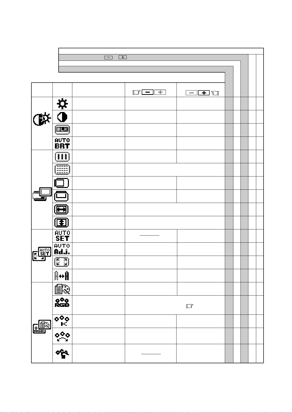
- 2-10 -
Pour sélectionner une
surface d’affichage normale.
Pour sélectionner une surface
d’affichage étendue.
Pour annuler la fonction
réglages automatiques.
Pour mettre en marche
la fonction réglages
automatiques.
Mémorisation usine
Mémorisation utilisater
5.1 Différents réglages
Presser les touches
et simultanément ramène au réglage memorisé en usine.
Appuyer “RÉGLAGES USINE” pour revenir à la configuration d’usine.
Fixe les valeurs pour chaque timing.
Les valeurs fixées ne sont pas affectées pas un changement de timing.
Appuyer sur la touche de de réglage:
Appuyer sur la touche de réglage:
Etre d'une couleur
noire foncée.
Etre d'une couleur
noire claire.
Diminue la luminosité.
Augmente la
luminosité.
Diminue le contraste.
Augmente le contraste.
Déplace l'image vers la
gauche.
Déplace l'image vers la
droite.
Pour r
é
tr
é
cir la largeur de
l'image sur l'écran vers la gauche.
Pour éliminer les parasitese.
Pour agrandir la largeur de
l'image sur l'écran vers la droite.
Permet de déplacer
l'image vers le bas.
Permet de déplacer
l'image vers le haut.
Pour revenir au mode
de réglage usine.
Affiche le mode texte.
Affiche le mode
graphique.
Pour inhiber la fonction
d’Auto-luminosité.
Pour opérer le fonction
d’Auto-luminosité.
Pour diminuer la
distinction.
Pour augmenter
la distinction.
Pour régler la hauteur de l’image.
Pour régler la taille horizontale de l’image.
sRGB, VIDEO, ORIGINE: Pas de réglages possibles.
Pour diminuer la
température de couleur.
Pour augmenter la
température de couleur.
La couleur est réglée sur le
symbole
‘’-‘’ situé àpar
gauche du vumètre.
La couleur est réglée
sur le symbole ‘’+’’ situé
à droite du vumètre.
Pour restaurer le réglages
de la température et du
contrôle des couleurs au
réglages usines
Pour sélectionner le mode couleur désiré sRGB,
VIDEO, ORIGINE and PERSO. (
P2-4)
Groupe
d’icônes
Icône Objet
LUMINOSITÉ ○○○○
CONTRASTE ○○○○
NIVEAU DE NOIR. ○○○○
AUTO LUMINANCE ○○○
HORLOGE ○○
PHASE D’HORLOGE ○○
POSITION HORIZONTALE
○○
POSITION VERTICALE ○○
RESOLUTION H ○○
RESOLUTION V ○○
REGLAGES AUTO. ‑‑‑‑‑
CORRECTION AUTO. ○○
PLEIN ÉCRAN ○○
FINESSE ○○○
MODE D’AFFICHAGE ○○○
COULEUR ○○○
TEMPÉRATURE COULEUR
○○○○
CONTRïLE COULEUR ○○○○
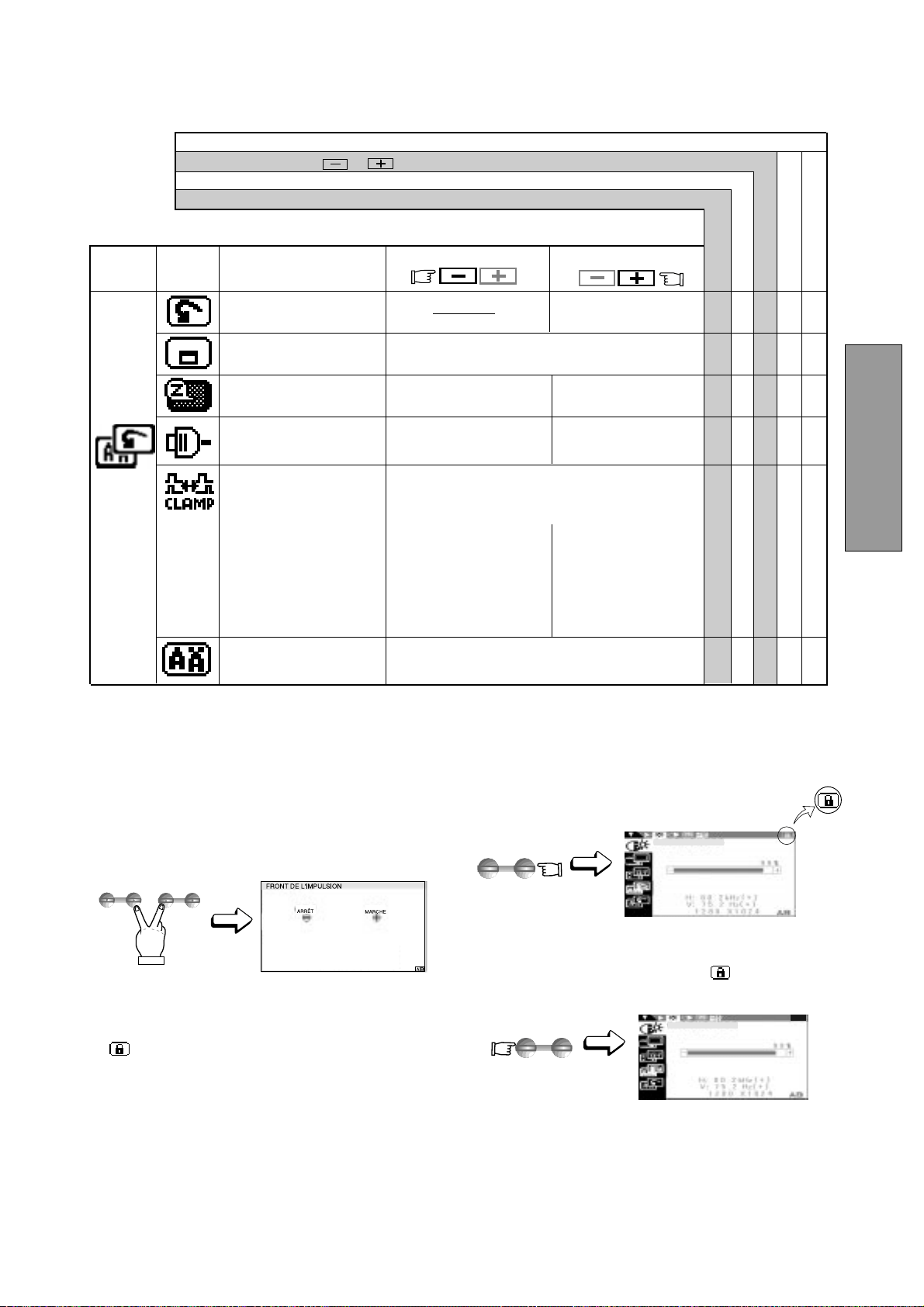
- 2-11 -
FRANÇAIS
Pour arrêter la fonction
S
É
LECTION AUTOMATIQUE.
Pour mettre en marche la
fonction SÉLECTION
AUTOMATIQUE.
Groupe
d’icônes
Icône
Objet
Appuyer sur la touche de
réglage:
Appuyer sur la touche de réglage:
Pour séectionner
fonctionement en mode
courant.
Pour rendre opérant le
mode économisateur
d’énergie.
Pour choisir le langage du Menu à L’écran.
ENG......Anglais, FRA......Français, ESP......Espagnol,
ITA......Italien, GER......Allemand, JPN......Japonnais
Pour bouger le menu à L’écran sur 5 positions
différentes.
Pour revenir au mode
de réglage usine.
Elimine l’excés de couleur verte ou lde luminosité qui
peuvent apparaître lorsqu’un signal de synchronisation
composite sur le vert et de synchronisation externe sont
appliqués simultanément sur les entrées du moniteur.
Synchronise le signal
vidéo sur le front montant
de l’impulsion de synchro
horizontale.
Synchronise le signal
vidéo sur le front descen-
dant de l’impulsion de syn-
chro horizontale. Si vous
utilisez un Macintosh
ancienne génération, vous
devez presser le bouton
“Plus”.
ADJUST
-
+
ADJUST
-
+
SELECT
ADJUST
Mémorisation usine
Mémorisation utilisater
Presser les touches et simultanément ramène au réglage memorisé en usine.
Appuyer “RÉGLAGES USINE” pour revenir à la configuration d’usine.
Fixe les valeurs pour chaque timing.
Les valeurs fixées ne sont pas affectées pas un changement de timing.
LUMINOSITÉ
LUMINOSITÉ
5.2 Mode VERROUILLAGE
1. Presser le bouton de sélection droit et le bouton de
réglage moins simultanément Le menu “FRONT DE
L’IMPULSION” apparaît à l’écran.
2. Presser le bouton plus pour verrouiller le Menu à
L’écran. En condition de verrouillage “Un symbole
de clé” est indiqué dans la partie haute et droite du
Menu à L’écran et seule la “LUMINOSITÉ” peut être
réglée.
Le signal A/B change et le bouton OSD OFF en face
avant est fonctionnel.
3. Presser le bouton moins pour déverrouiller le menu à
L’écran, si vous appuyez n’importe quel bouton de
sélection ou de réglage, le symbole
de clé disparaît,
vous pouvez alors de nouveau utiliser le Menu à
L’écran.
RÉGLAGES USINE ‑‑‑‑‑
POSITION DU MENU ○○○
ECONOMIE ÉNERGIE ○○○
SÉLEC.ENTRÉE AUTO. ○○○
FRONT DE SYNCHRO ○○○
LANGUE ○
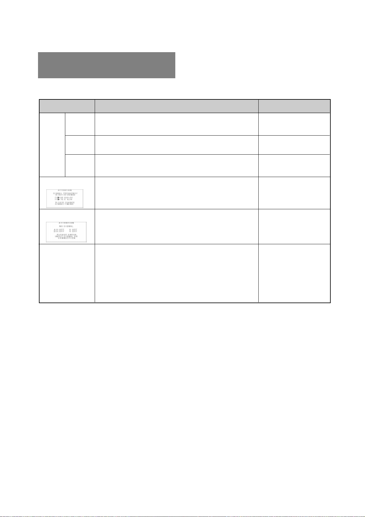
- 2-12 -
6
6 DEPANNAGE
PROBLEME
EMPLACEMENT
POINTS A VERIFIER
Images illisibles,
position anormale de
l’image, image trop
petite ou trop grande
Le message suivant
apparaît.
Le message suivant
apparaît.
Pas
d’image
LED
allumee
(VERT)
LED
allumee
(Ambre)
LED
éteinte
• Contraste luminosité
• Interrupteur de mise en marche
• Câble d’alimentation no connecté
• Câble vidéo non connecté
• Systeme non allumé
• La fonction économiseur d’énergie est active?
• Incompatibilite avec la fréquence de la source graphique.
• La résolution affichée est en dehors des spécifications.
• Câble vidéo non connecté
• Systeme non allumé
• La fonction économiseur d’énergie est active?
• Régler, RESOLUTION, HORLOGE, PHASE D’HORLOGE, PO-
SITION HORIZONTALE et POSITION VERTICALE avec un
signal non standard.
• Le moniteur peut ne pas obtenir une image plein écran, selon le
signal. Dans ce cas, sélectionner une autre résolution, ou une
autre fréquence de rafraîchissement écran.
• Régler la taille à la position horizontales et verticales attendez
quelques secondes après avoir effectué le réglage de la taille
avant de déconnecter ou d’eteindre le moniteur.
• Face avant
• Face avant
• Face arrière
• Face arrière
• Système
• Contrôler les specifica-
tions de la source
graphique et du moniteur.
• Face arrière
• Système
• Face avant (OSM
MC
)
• Face avant (OSM)
Avant de retourner votre moniteur auprès de votre
revendeur, assurez vous que les points suivants soient
respectés.
Dans le cas d'une utilisation sous un signal vidéo stan-
dard, Contrôler que les signaux de votre unité centrale soit
conformes avec celles définies en 7. SPÉCIFICATIONS.
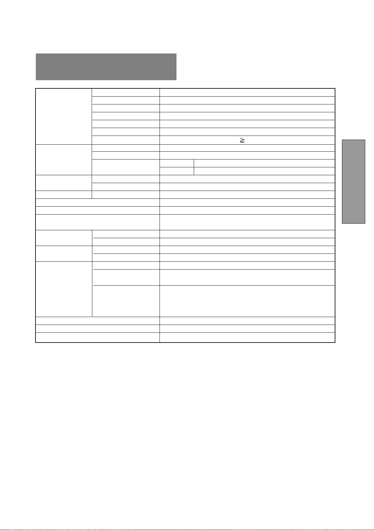
- 2-13 -
FRANÇAIS
7
Panneau LCD 46cm/18,1" TFT couleur
Type Matrice Active
Résolution 1280 dots x 1024 lignes
Pas du Pixel 0,28mm
Structure Pixel R, V, B bande verticale
Traitement du panneau Anti-reflet, Protection haute résistance
Angle de vue ±80°(Horizontal / Vertical) CR 5
Vidéo 0,7Vp-p analogique RVB
Sync Synchronisation sur le vert ou séparée H/V ou synchronisation
composée
Impédance Vidéo 75
ΩΩ
ΩΩ
Ω
déntrée Sync 2,2k
ΩΩ
ΩΩ
Ω
SCANNING Horizontal 24,0 - 80,0kHz
FREQUENCY Vertical 50,0 - 86,0Hz
DIMENSIOND’IMAGE
H x V 359mm x 287,2mm
NOMBRE DE COULEURS 16,77 Million Colors
LUMINOSITÉ(avec un signal blanc standard) 200 cd/m
2
(Typ.)
CONNECTEUR D’ENTRÉE SIGNAUX D-SUB-15P (Un avec un câble de signal détachable, et l’autre est
dérrière le couvercle des câbles)
CONDITION DE Température 5 - 35°C
FONCTION Hygrométrie 10 - 90%RH (sans condensation)
ALIMENTATION Moniteurs LCD 55W MAX
Adaptateur-AC ENTREE: AC100~240V±10%, 50/60Hz SORTIE: DC15V
Sécurité UL1950 (UL), CSA C22,2 No.950 (C-UL), EN60950(TÜV-GS)
EMC FCC Classe-B, DOC Classe-B, EN55022 Classe-B, EN50082-1
VCCI Classe-B, EN61000-3-3
Autres CE-Marking, MPR-II,TCO '99,
ISO 9241-3, ISO 9241-7, ISO 9241-8(TÜV-GS)
International E
NERGY STAR
Energy 2000 Labeling Award
(B)18,1" x (H)18,9" x (T)8,7"/ (B)460mm x (H)481mm x (T)220mm
8,2kg (18,1lbs.) (sans l’adaptateur AC Adapter et les câbles)
SOCLE PIVOTANT ET INCLINABLE -5° ~ +35° Angle d’inclinaison ±45° Angle de rotation
BOITIER
POIDS
PANNEAU LCD
7 SPÉCIFICATIONS
SIGNAUX
DÉNTREE
NORMES

- 2-14 -
GARANTIE LIMITÉE
NEC-Mitsubishi (ci-après «NEC-MITSUBISHI») garantit
que ce produit est exempt de vice de fabrication et de
main-d’oeuvre et, selon les conditions énoncées ci-
dessous, accepte de réparer ou remplacer, à sa discrétion,
toute pièce de l’appareil concerné qui s’avérerait
défectueuse et ce, pendant une période de trois (3) ans à
partir de la date d’achat initial. Les pièces de rechange
sont garanties pendant quatre-vingt dix (90) jours. Les
pièces de rechange ou unités peuvent être neuves ou
reconditionnées et seront conformes aux spécifications
des pièces et des unités d’origine.
Cette garantie vous accorde des droits légaux spécifiques
auxquels peuvent s’ajouter d’autres droits pouvant varier
d’une juridiction à l’autre. Cette garantie est limitée à
l’acheteur d’origine du produit et n’est pas transférable.
Cette garantie couvre uniquement les composants fournis
par NEC-MITSUBISHI. Une réparation requise à la suite
de l’utilisation des pièces provenant d’un tiers n’est pas
couverte par cette garantie. Pour être couvert par cette
garantie, le produit doit avoir été acheté aux États-Unis ou
au Canada par l’acheteur d’origine. Cette garantie couvre
uniquement la distribution du produit aux États-Unis ou au
Canada par NEC-MITSUBISHI. Aucune garantie n’est
offerte à l’extérieur des États-Unis et du Canada. La
preuve d’achat sera exigée par NEC-MITSUBISHI pour
prouver la date d’achat. Une telle preuve d’achat doit être
une facture de vente d’origine ou un reçu reprenant le nom
et l’adresse du vendeur, de l’acheteur et le numéro de
série du produit.
Pour obtenir un service au titre de la garantie, vous devez
expédier le produit en port prépayé ou le déposer chez le
revendeur agréé qui vous l’a vendu ou dans un autre
centre autorisé par NEC-MITSUBISHI, soit dans
l’emballage d’origine, soit dans un emballage similaire
procurant un niveau équivalent de protection. Avant de
retourner tout produit à NEC-MITSUBISHI, vous devez
d’abord obtenir une autorisation de retour de marchandise
en composant le 1-800-632-4662.
Le produit ne pourra avoir été enlevé ou modifié, réparé ou
entretenu au préalable par personne d’autre que du
personnel technique autorisé par NEC-MITSUBISHI, et le
numéro de série du produit ne pourra pas avoir été enlevé.
Pour être couvert par cette garantie, le produit ne pourra
pas avoir été soumis à l’affichage d’une image fixe pen-
dant de longues périodes de temps résultant en une
persistance de l’image, un accident, une utilisation
incorrecte ou abusive ou une utilisation contraire aux
directives contenues dans le guide de l’utilisateur. Une
seule de ces conditions annulera la garantie.
NEC-MITSUBISHI NE POURRA ÊTRE TENUE
RESPONSABLE DE DOMMAGES DIRECTS,
INDIRECTS, ACCIDENTELS, SECONDAIRES OU
D’AUTRES TYPES DE DOMMAGES RÉSULTANT DE
L’UTILISATION D’UN PRODUIT QUI N’ENTRENT PAS
SOUS LA RESPONSABILITÉ DÉCRITE CI-DESSUS.
CES GARANTIES REMPLACENT TOUTE AUTRE
GARANTIE EXPLICITE OU IMPLICITE, Y COMPRIS,
MAIS SANS S’Y LIMITER, TOUTE GARANTIE DE
QUALITÉ MARCHANDE OU D’APTITUDE À UNE FIN
PARTICULIÈRE. CERTAINES JURIDICTIONS NE
PERMETTANT PAS L’EXCLUSION DE GARANTIES
IMPLICITES OU LA LIMITATION OU L’EXCLUSION DE
RESPONSABILITÉ POUR DOMMAGES ACCIDENTELS
OU SECONDAIRES, LES EXCLUSIONS OU LIMITA-
TIONS CI-DESSUS POURRAIENT NE PAS
S’APPLIQUER DANS VOTRE CAS.
Ce produit est garanti selon les termes de cette garantie
limitée. Les consommateurs doivent savoir que les perfor-
mances du produit peuvent varier selon la configuration
du système, le logiciel, l’application, les données du client
et la manière dont le produit est utilisé par l’opérateur,
ainsi que d’autres facteurs. Bien que les produits NEC-
MITSUBISHI soient considérés compatibles avec de
nombreux systèmes, la mise en oeuvre fonctionnelle du
produit peut varier d’un client à l’autre. Par conséquent,
l’adéquation d’un produit à un besoin ou une application
spécifique doit être déterminée par le consommateur et
n’est pas garantie par NEC-MITSUBISHI.
Pour connaître le nom du centre de service technique
agréé NEC-MITSUBISHI le plus proche, appeler NEC-
MITSUBISHI au 1-800-632-4662.
- 3-1 -
DEUTSCH
INHALTSVERZEICHNIS
1. EINLEITUNG....................................................... 3-2
1.1 Eigenschaften ......................................... 3-2
1.2 Interner Anzeigemodus-Speicher ........... 3-2
1.3 IPM
TM
(Intelligent Power Manager)
Funktion .................................................. 3-3
1.4 DDC ........................................................ 3-3
1.5 Auswahl des Anzeigemodus .................. 3-3
1.6 Automatische Korrekturfunktion ............. 3-3
1.7 Automatische Erweiterungsfunktion ....... 3-3
1.8 Automatische Eingangsauswahl............. 3-3
1.9 Automatische Helligkeitsfunktion............ 3-3
1.10 AccuColor
®
Control System .................... 3-4
1.11 Betriebshinweise..................................... 3-4
1.12 Reinigung lhres Monitors........................ 3-4
1.13 Auspacken .............................................. 3-4
1.14 Dreh-/Kippfuß ......................................... 3-4
Justierung des Bildschirms..................... 3-4
1.15 Kurzinstallationsanweisung .................... 3-5
2. BEDIENELEMENTE UND ANSCHLÜSSE ......... 3-6
2.1 Bedienelemente...................................... 3-6
2.2 Funktion .................................................. 3-6
3. INSTALLATION UND ANSCHLUß...................... 3-7
3.1 Anschluß des Netzkabels ....................... 3-7
3.2 Anschluß des Signalkabels .................... 3-7
3.2.1 Anschluß an IBM VGA kompatibles
System ............................................. 3-7
3.2.2 Anschluß an Apple Macintosh
Computer ......................................... 3-8
3.2.3 Anschluß an zwei Computer ............. 3-8
4. AUTOMATISCHE EINSTELLFUNKTION ........... 3-9
5. OSM
TM
BEDIENUNG ........................................... 3-9
5.1 Einstellfunktionen ................................... 3-10
5.2 Benutzung der OSD Sperrung................ 3-11
6. STÖRUNGSSUCHE ........................................... 3-12
7. SPEZIFIKATIONEN ............................................ 3-13
BESCHRÄNKTE GEWÄHRLEISTUNG .................... 3-14
ACHTUNG
Entfernen Sie nie die Rückwand dieses Gerätes, da Sie
sich dadurch sehr hohen Spannungen und anderen
Gefahren aussetzen können.
HERSTELLER-KONFORMITÄTSERKLÄRUNG ZUR
CE-KENNZEICHUNUNG:
Wir, NEC-MITSUBISHI ELECTRIC VISUAL SYSTEMS
CORPORATION erklären in alleiniger Verantworlung,
daß das Produkt auf das sich diese Erklärung bezieht,
mit der/den folgenden Normen oder normativen
Dokumenten übereinstimmt:
EN60950
EN55022 Klasse B
EN50082-1
EN61000-3-3
Gemäß den Bestimmungen der Richtlinien:
73/23/EEC Niederspannungsrichtlinie
89/336/EEC EMV Richtlinie
ACHTUNG!
Dieses Produkt ist nicht für den Gebrauch in
Zusammenhang mit lebenserhaltenden Geräten
geeignet und die NEC-MITSUBISHI ELECTRIC VI-
SUAL SYSTEMS CORPORATION macht keinerlei
gegensätzliche Darstellungen.
Lebenserhaltende Geräte sind solche, die zum Messen,
Diagnostizieren oder für die Auswertung von Gewebe,
Systemen oder Funktionen des menschlichen Körpers
benutzt werden; oder andere Geräte die angewendet
werden, um das Leben oder die Gesundheit zu
unterstützen oder zu erhalten.
Warenzeichen
IBM, PC, PS/2, PS/V, Personal System/2 sind eingetragene
Warenzeichen der International Business Machines Corp.
Apple Macintosh, Quadra sind eingetragene Warenzeichen der
Apple Computer, Inc.
UNIX ist ein eingetragenes Warenzeichen in den Vereinigten
Staaten und anderen Ländern, lizensiert ausschließlich durch X/
Open Company Limited.
E
NERGY
S
TAR
ist eine eingetragenes U.S. Warenzeichen.
NEC ist eine eingetragenes Warenzeichen der NEC Corporation.
Alle sonstigen Warenzeichen oder eingetragene Warenzeichen
sind Besitz ihrer jeweiligen Inhaber.
© 2000 NEC-MITSUBISHI Electronics Display of America, Inc.

- 3-2 -
1
1
EINLEITUNG
Wir gratulieren Ihnen zum Kauf des hochauflösenden
MultiSync LCD1800
TM
Farbmonitors.
Dieses Handbuch beschreibt den Anschluß, die Einstellung
und die Pflege lhres MultiSync LCD1800 Monitors.
Außerdem sind technische Spezifikationen und ein Kapitel
zur Störungssuche enthalten.
1.1 Eigenschaften
Bei dem Modell MultiSync LCD1800 mit 46cm/18.1",
Bildschirmdiagonale handelt es sich um einen intelligenten,
mikroprozessorgesteuerten LCD Monitor, der zu den
meisten analogen RGB (Rot, Grün, Blau) Standards
kompatibel ist.
Er ermöglicht die Wiedergabe von Texten und
Grafikdarstellungen sowohl für PC-als auch für Macintosh-
Systemen.
Duale Eingänge
Bietet duale Eingänge, so daß Sie zwei Systeme an
den Monitor anschließen können. Durch Antippen
einer Taste am vorderen Bedienfeld können Sie ganz
einfach zwischen zwei Computern umschalten.
Minimierte Stellfläche
Die ideale Lösung auch für räumlich beengte
Bildschirmarbeitsplätze -hervorragende Bildqualität bei
minimaler Bildschirmgröße und geringem
Bildschirmgewicht. Der geringe Platzbedarf und das
geringe Gewicht ermöglichen den problemlosen Trans-
port des Gerätes von einer Einsatzstelle zur nächsten.
AccuColor
®
Control System
Über das Color Control System können die Farben
Ihres Bildschirmes exakt eingestellt und die
Farbintensität einer Vielzahl von Anforderungen
angepaßt werden.
OSM
TM
(On Screen Manager)
Der On Screen Manager erlaubt eine direkte,
menügesteuerte Einstellung individueller
Bildparameter.
ErgoDesign
®
Das ergonomische Design verbessert die
Arbeitsumgebung, schützt die Gesundheit des
Benutzers und ermöglicht auch finanzielle
Einsparungen. Als Beispiele seien hier die OSM-
Regler für eine schnelle und einfache Einstellung der
Bildqualität, der Standfuß mit Schwenk- und
Neigemöglichkeit des Bildschirms für einen optimalen
Blickwinkel, die platzsparende Stellfläche sowie die
Zertifizierungen nach TCO (inkl. MPRII-Richtlinien)
genannt.
Plug & Play
Plug & Play ist die in Windows
®
integrierte Lösung von
Microsoft
®
bei der Einrichtung und Installation von
Peripheriegeräten. Der Monitor teilt seine
Leistungsmerkmale (wie z.B. Bildschirmgröße und
Auflösung) direkt Ihrem Computer mit, so daß von
diesem automatisch das bestmögliche Bild eingestellt
wird.
IPM
TM
-System (Intelligent Power Manager)
Der Intelligent Power Manager (intelligenter
Energieverwalter) ist eine fortschrittliche Einrichtung
zum Energiesparen. Bei Arbeitspausen am LCD-Moni-
tor werden 2/3 an Energiekosten eingespart,
Wärmeemissionen reduziert, wodurch der
Klimatisierungsaufwand am Arbeitsplatz geringer wird.
Multi-Frequenz-Technologie
Die Multi-Frequenz-Technologie hat die Eigenschaft,
daß die horizontale und vertikale Frequenz bei allen
Bildschirmauflösungen automatisch eingestellt wird.
FullScan
TM
FullSan bietet die Möglichkeit, bei den meisten
Bildschirmauflösungen immer die maximale
Bildschirmfläche zu nutzen.
VESA-Standardschnittstelle
Über diese Schnittstelle kann der MultiSync-Monitor
an jeden VESA-Standard-Montagearm bzw.
Montagerahmen angeschlossen werden. Der Monitor
kann an der Wand oder zur Benutzung an umliegenden
Arbeitsplätzen an einem Arm installiert werden.
XtraView
®
Diese Technologie ermöglicht die Betrachtung des
Bildes aus fast jedem beliebigen Winkel an der
Frontseite des Monitors. Der Betrachtungswinkel
beträgt nach oben, unten, links und rechts volle 160
Grad.
1.2 Interner Anzeigemodus-Speicher
Um den Einstellaufwand für den Benutzer so gering wie
möglich zu halten, wurden werksseitig bereits die in
Tabelle 1 aufgelisteten Bildschirmstandards
abgespeichert. Erkennt der Monitor einen dieser Stan-
dards, werden Bildlage und -größe automatisch justiert.
Diese Voreinstellungen können unter Benutzung der
Bedienelemente überschrieben werden. Zusätzlich zu
den werksseitig eingestellten Timings können bis zu 7
weitere Timings abgespeichert werden. Um als neues
Timing erkannt zu werden, muß das neue Videosignal in
der Horizontalfrequenz um mindestens 1kHz, in der
Vertikalfrequenz um mindestens 1Hz oder in der Polarität
der Synchronsignale von sämtlichen bereits
abgespeicherten Timings abweichen.
Tabelle 1. Werksseitige Voreinstellungen
VOREINGESTELLTES
TIMING
Fh(kHz)
Fv (Hz) H V
640 x 480 N.I. 35.0 66.7
--
832 x 624 N.I. 49.7 74.6
--
1152 x 870 N.I. 68.7 75.0
--
640 x 350 N.I. 31.4 70.0
+
-
640 x 480 N.I. 31.5 59.9
--
640 x 480 N.I. 37.5 75.0
--
640 x 480 N.I. 43.3 85.0
--
720 x 400 N.I. 31.5 70.0
-
+
800 x 600 N.I. 37.9 60.3
++
800 x 600 N.I. 48.1 72.2
++
800 x 600 N.I. 46.9 75.0
++
800 x 600 N.I. 53.7 85.0
++
1024 x 768 N.I. 48.4 60.0
--
1024 x 768 N.I. 56.5 70.1
--
1024 x 768 N.I. 58.1 72.1
--
1024 x 768 N.I. 60.2 75.0
++
1024 x 768 N.I. 68.7 85.0
++
1280 x 1024 N.I. 64.0 60.0
--
1280 x 1024 N.I. 80.0 75.0
++
Polarität
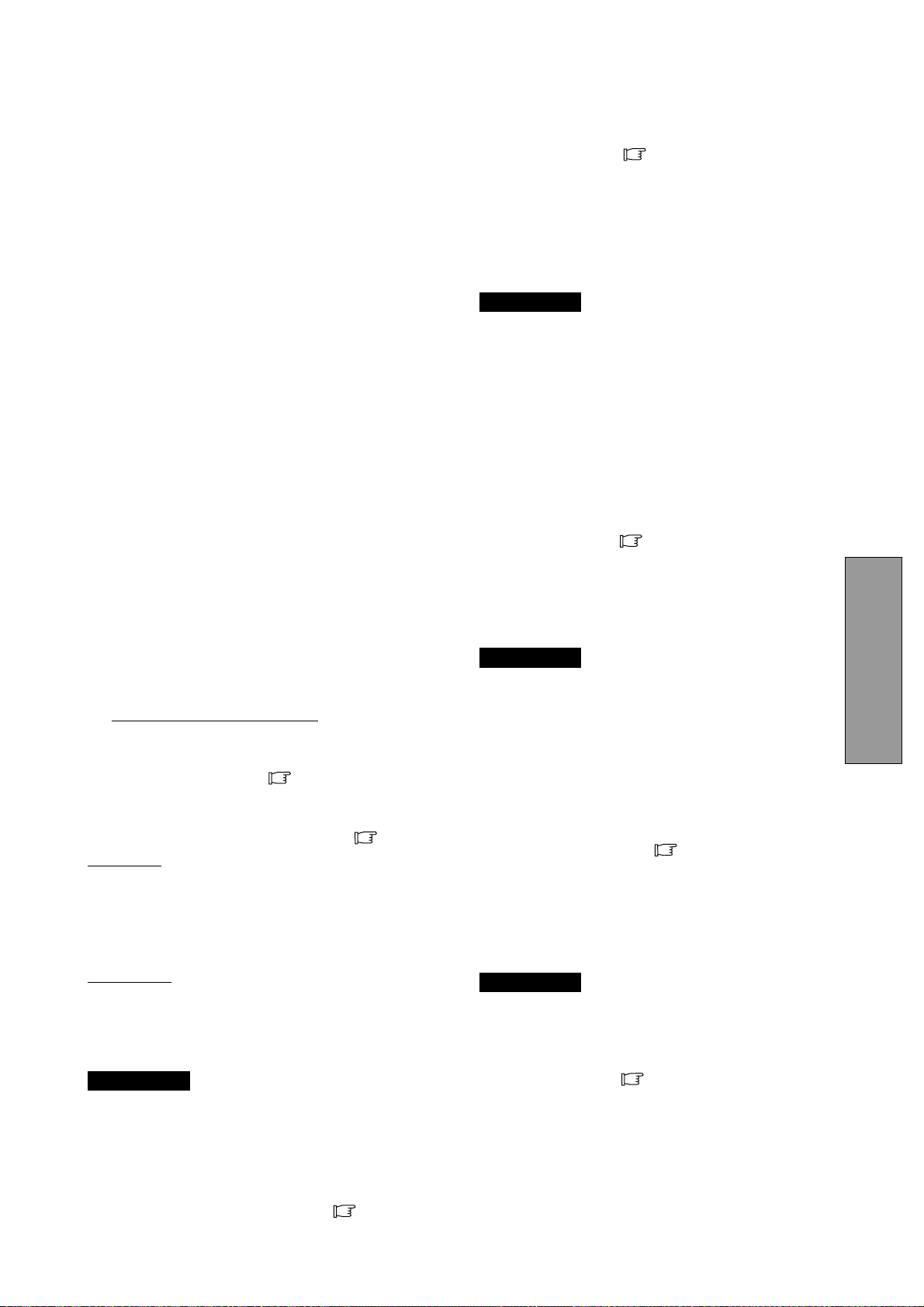
- 3-3 -
DEUTSCH
1.3 IPM
TM
(Intelligent Power Manager) Funktion
Dieser Monitor besitzt eine Energiesparfunktion, welche
die Leistungsaufnahme reduziert, wenn der Monitor nicht
benutzt wird.
Bei Fehlen des horizontalen Synchronsignals und/oder
des vertikalen Synchronsignals schaltet der Monitor nach
ungefähr 10 Sekunden in den Energiesparmodus, der
den Energieverbrauch auf weniger als 3W reduziert. Im
Energiepsarmodus ist der Bildschirm dunkel und die
Betriebsanzeige leuchtet bernsteinfarben.
Bei Wiederanlegen beider Synchronsignale erscheint das
Bild innerhalb von 3 Sekunden wieder.
Zur Aktivierung dieser Funktion beziehen Sie sich bitte auf
das Handbuch zu lhrem Computer.
1.4 DDC
Dieser Bildschirm ist mit der DDC
TM
2B Funktion
ausgestattet, besser bekannt als “Plug & Play”. DDC
(Display Data Channel) ist ein Übertragungskanal, über
den der Bildschirm dem Computer automatisch seine
Leistungsmerkmale mitteilt (z.B. jeden unterstützten
Bildschirmmodus mit dem entsprechenden Timing
(Signalaufbau)).
DDC benutzt einen Stift des 15-Stift-VGA-Steckers, der
vorher nicht verwendet wurde. Das System wird die “Plug
& Play”-Funktion nur dann ausführen, wenn sowohl
Bildschirm als auch Computer mit der DDC Funktion
ausgerüstet sind.
Beim Starten eines Plug & Play fähigen PCs, erkennt
dieser den Monitor und lädt automatisch den passenden
Treiber. Falls der Treiber nicht auf dem PC installiert ist,
erscheint ein eine Dialogbox, die nach dem Ort fragt, an
dem der Treiber gefunden werden kann.
Der neueste Treiber kann von der NEC-MITSUBISHI
Homepage
>>
http://www.necmitsubishi.com/ heruntergeladen
werden.
1.5 Auswahl des Anzeigemodus
(“ANZEIGEMODUS” S.3-10)
Die beiden folgenden Display Modi stehen zur Verfügung.
Sie können den Modus, der Ihren Anforderungen
entspricht, mittels des OSM
TM
auswählen ( S.3-10).
Text Modus
Bei Verwendung dieses Modus wird der Kontrast unter
Vernachlässigung einer exakten Farbwiedergabe betont.
Dieser Modus eignet sich für Anwendungen, in denen die
Genauigkeit der Farbwiedergabe weniger wichtig ist, wie
z.B. Dokumentenerstellung, Kalkulationen oder
Datenbanken etc.
Grafik Modus
Dieser Modus ist für die Exaktheit der Farbwiedergabe
optimiert. Dieser Modus eignet sich besonders für
Anwendungen, in denen die exakte Farbwiedergabe
entscheidend ist, z. B.: Bildbearbeitung, Erstellung von
Illustrationen etc.
ANMERKUNG
• Im Auslieferzustand ist die Funktion
“ANZEIGEMODUS” auf “GRAFIK” eingestellt.
• Führen Sie bitte die Funktion “AUTOEINSTELLUNG”
durch, bevor Sie den Modus “GRAFIK” auswählen.
Ansonsten könnte der Bildschirm zu hell werden.
• Bevor Sie eine “Farbkalibrierung” durchführen, setzen
Sie bitte die Funktion “FARBE” auf “NATIVE” und
“ANZEIGEMODUS“ auf “GRAFIK” (
S.3-10).
1.6 Automatische Korrekturfunktion (“AUTOM.-
KORREKTUR”
S.3-10)
Diese Funktion dient dazu, “TAKTPHASE” automatisch
und periodisch (alle 30 min.) einzustellen, um Änderungen
des Eingangssignals oder der Umgebungstemperatur
auszugleichen, und um die Funktionen “TAKTPHASE”,
“HORIZONTALE BILDLAGE” und “VERTIKALE
BILDLAGE” beim Einschalten oder dem Wechsel des
Eingangssignals einzustellen.
ANMERKUNG
• Im Auslieferungszustand ist “AUTOM.-KORREKTUR”
auf “AUS” gesetzt.
• In Verbindung mit einigen PC’s kann es sein, daß die
Funktion “AUTOM.-KORREKTUR” nicht korrekt
funktioniert. Stellen Sie sie in diesem Fall auf “AUS”.
• Wenn “AUTOM.-KORREKTUR” auf “EIN” gestellt ist,
kann es sein, daß Sie kurzzeitig den Eindruck haben,
das Bild würde während einer Animation oder der
Mausbenutzung stillstehen. Dies ist kein Defekt,
sondern entsteht durch die Wirkung der “AUTOM.-
KORREKTUR”- Funktion.
1.7 Automatische Erweiterungsfunktion
(“VOLLBILD”
S.3-10)
Diese Funktion dient zur automatischen Erweiterung des
Bildes. Durch eine Kantenglättungsfunktion erhalten Sie
eine saubere Darstellung auch bei erweiterter Darstellung.
Diese Funktion steht für Signale mit 1024 Bildpunkten und
768 Linien oder weniger beim Monitor zur Verfügung.
ANMERKUNG
• Bei einigen Auflösungen, auch wenn sie o. a.
Bedingungen entsprechen, ist es möglich, daß das
Bild nicht auf die ganze Bildschirmgröße vergrößert
werden kann.
• Bei einigen Eingangssignalen wird das Bild vertikal
oder horizontal nicht vergrößert.
• Bei einigen Auflösungen kann das Bild leicht unscharf
erscheinen.
1.8 Automatische Eingangsauswahl (“AUTOM.-
EINGANGSWAHL”
S3-11)
Bei Aktivierung dieser Funktion wird automatisch der
Eingang ausgewählt, an dem ein Eingangssignal anliegt.
Für den Fall, daß zwei Computer gleichzeitig
angeschlossen sind, wird automatisch auf den zweiten
Eingang umgeschaltet, sobald der erste Computer in
einen Energiesparmodus schaltet.
ANMERKUNG
• Im Auslieferungszustand befindet sich die Funktion,
“AUTOM.-EINGANGSWAHL” auf der Position “EIN”.
1.9 Automatische Helligkeitsfunktion (“AUTOM.
HELLIGKEIT”
S.3-10)
Diese Funktion paßt die Helligkeit automatisch auf die
Größe des weißen Bildschirmbereichs an, um dem
Blendungseffekt entgegen zu wirken.
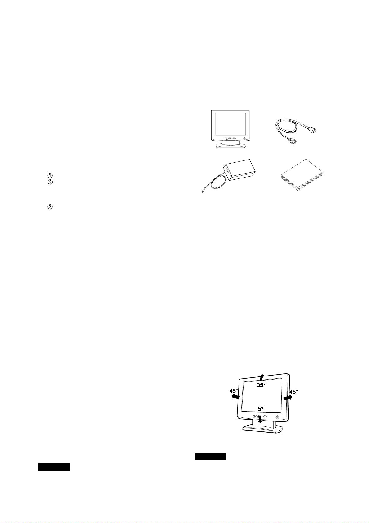
- 3-4 -
1.10 AccuColor
®
Control System
Die folgenden Farbdarstellungsmodi stehen Ihnen zu
Verfügung:
1. sRGB: 1. Der sRGB-Modus verbessert durch einen
einzigen, standardisierten RGB-Farbraum die
Farbtreue in der Desktopumgebung dramatisch. Mit
Hilfe dieser Farbumgebung ist es dem Anwender
möglich, die Farbe in den meisten Situationen ohne
den Ballast eines zusätzlichen Farbmanagementsystems
leicht und sicher zu kommunizieren. Wir empfehlen
die Benutzung bei Einstellung auf “Grafik”-Modus.
Nicht einstellbar.
2. VIDEO: Geignet für die Wiedergabe von Animationen.
Nicht einstellbar.
3. NATIVE: Original Farbwiedergabe des LCD Panels.
Nicht einstellbar.
4. BENUTZER: Die folgenden Einstellmöglichkeiten
stehen zur Verfügung.
FARBTEMPERATUR: 5000K~9600K
FARBSTEUERUNG:Diese Funktion ermöglicht die
unabhängige Einstellung 6 einzelner Farbanteile
(Rot, Grün, Blau, Gelb, Magenta und Cyan) und
der Farbsättigung.
FARBRÜCKSTELLUNG:Um die Farbtemperatur
und die Farbsteuerung auf die werksseitigen
Voreinstellungen zurückzusetzen.
1.11 Betriebshinweise
Bitte beachten Sie bei der Aufstellung und dem Betrieb
lhres Monitors folgende Hinweise:
• Stellen Sie den Monitor nicht vor einem hellen
Hintergrund oder dort auf, wo das Sonnenlicht oder
andere helle Lichtquellen direkt auf den Monitor
scheinen, um eine Anstrengung der Augen zu
vermeiden. Um eine höchstmögliche Ergonomie zu
gewährleisten, sollte der Monitor so aufgestellt werden,
daß er sich unterhalb der Augenhöhe befindet.
• Decken Sie die Entlüftungsöffnungen des Monitors
nicht zu. Sorgen Sie für ausreichende Belüftung, damit
die im Monitor entstehende Wärme abgeführt werden
kann.
• Schützen Sie den Monitor vor Regen, Feuchtigkeit
und Staub, um einen Brand oder Stromstöße zu
vermeiden.
• Achten Sie darauf, daß weder der Monitor, noch ein
anderer schwerer Gegenstand auf dem Netzkabel
stehen. Eine Beschädigung des Netzkabels kann einen
Brand oder Stromstöße verursachen.
• Behandeln Sie den Monitor vorsichtig beim Transport.
• Vermeiden Sie jede Art von Stößen oder Kratzern, da
der Bildschirm zerbrechlich ist.
1.12 Reinigung lhres Monitors
Beachten Sie bei der Reinigung lhres Monitors bitte
folgende Hinweise:
• Ziehen Sie vor der Reinigung immer den Netzstecker
aus der Steckdose.
• Reinigen Sie den Bildschirm und das Gehäuse mit
einem weichen Tuch.
• Sprühen Sie Reiniger niemals direkt auf den Monitor,
da übermässige Flüssigkeit in den Monitor eindringen
und es zu Schäden führen könnte.
ACHTUNG
Reinigen Sie das Gerät nicht mit Benzol, Verdünnern oder
anderen flüchtigen Stoffen, da die Oberfläfche durch
diese Stoffe beschädigt werden könnte. Vermeiden Sie
längeren Kontakt mit Gummi- oder Vinylprodukten.
1.13 Auspacken
Nach dem Auspacken lhres Farbmonitors sollten alle in
Bild 1 aufgeführten Teile vorhanden sein. Verwahren Sie
den Originalkarton und das Verpackungsmaterial, falls
Sie den Monitor später versenden oder transportieren
müssen.
1. LCD1800
TM
Farbmonitor
2. Netzkabel
3. AC Adapter
4. Bedienungsanleitung (Dieses Dokument)
1.14 Dreh-/Kippfuß
Der Monitor wird mit einem Dreh-/Kippfuß geliefert. Er
ermöglicht die Ausrichtung des Monitors nach den
Anforderungen des Benutzers für größtmögliche
Ergonomie.
Justierung des Bildschirms
Fassen Sie den Bildschirm an den gegenüberliegenden
Seiten, wie in Bild 2 gezeigt, an und stellen Sie den
gewünschten Dreh- und Kippwinkel ein. Bitte stellen Sie
den Monitor wie unten erklärt ein.
ACHTUNG
Bitte vermeiden Sie die Berührung der beweglichen Teile
des Dreh-und Schwenkfußes, um ein Einklemmen zu
vermeiden.
Bild 2
Bild 1
-
+
1
2
3
4
-
+
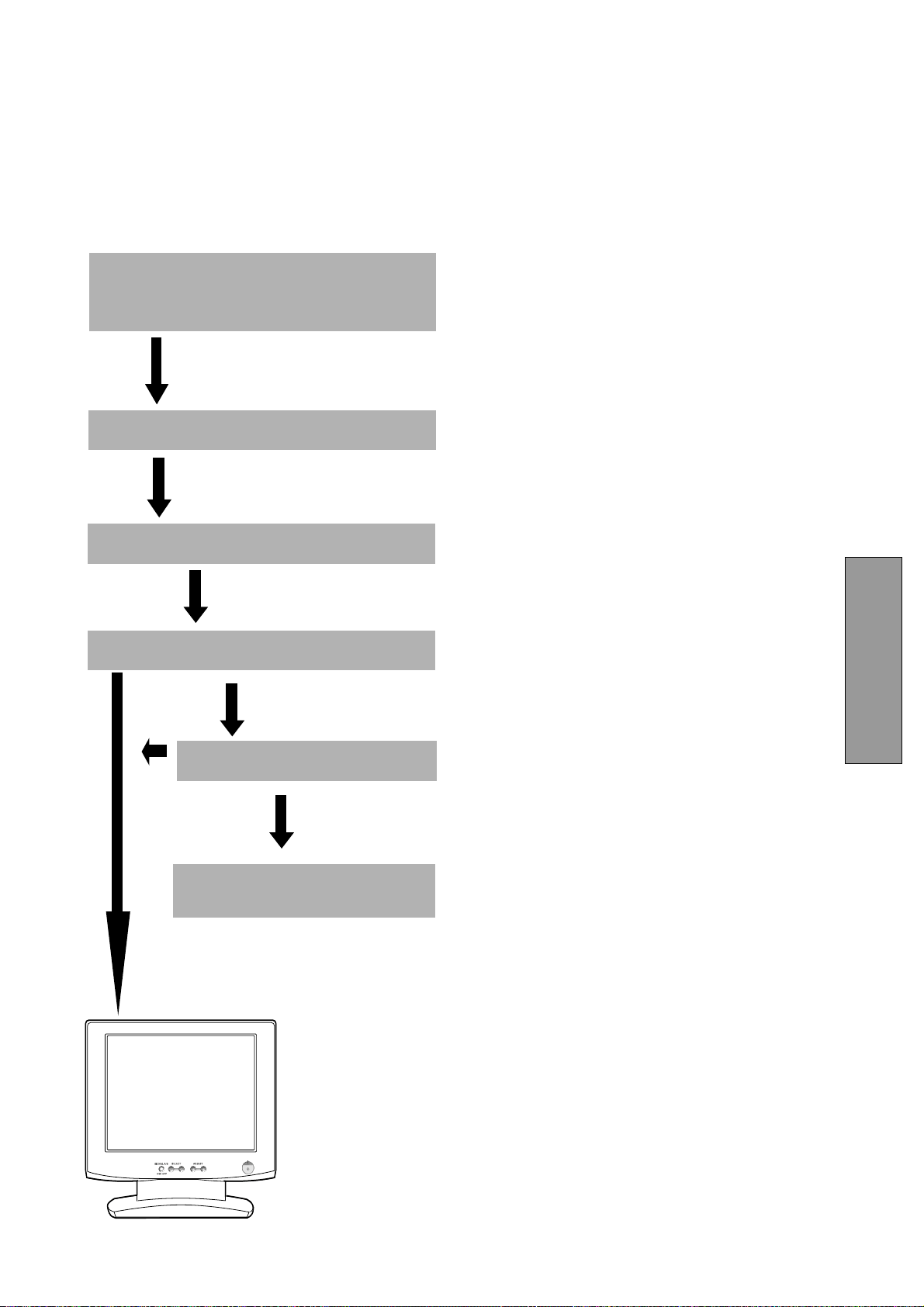
- 3-5 -
DEUTSCH
1.15 Kurzinstallationsanweisung
Die nachfolgende Abbildung erläutert den Anschluß lhres
Computers und Adapters an den Farbmonitor der
LCD1800
TM
und die Einstellung des Monitors.
OK
OK
Siehe 6. STÖRUNGSSUCHE
Schalten Sie den Computer ein.
Schalten Sie den MultiSync LCD1800 Monitor ein.
Stellen Sie den Monitor nach lhren Bedüfnissen ein.
Bei Auftreten eines Problems
Läßt sich das Problem
nicht beheben
Wenden Sie sich an den autorisierten
Product Support.
Schließen Sie das Netzkabel an den MultiSync
LCD1800 Farb LCD Monitor an und verbinden Sie mit
das Signalkabel mit den MultiSync LCD1800 und den
Computer.
-
+
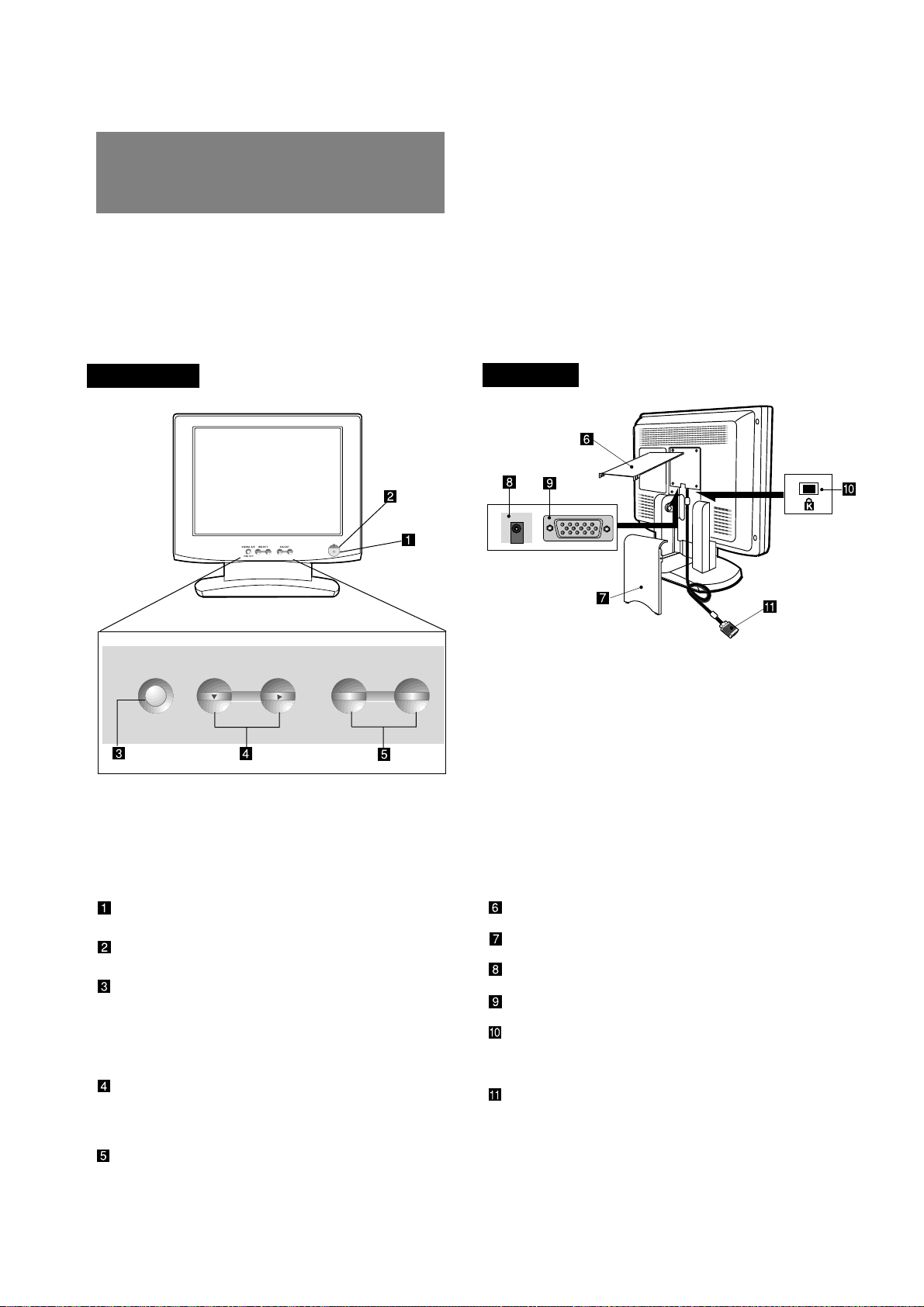
- 3-6 -
2
2.1 Bedienelemente
Bild 3 und 4 zeigen die Position der einzelnen
Bedienelemente. Jedes Bedienelment ist mit einer Ziffer
versehen und im Folgenden einzeln beschrieben.
KABELABDECKUNG (OBERE)
KABELABDECKUNG (UNTERE)
DC NETZBUCHSE
EINGANGSANSCHLUß (SIGNAL B)
BEFESTIGUNGSLOCH für
DIEBSTAHLSICHERUNGSSYSTEM: verfügbar
für KENSINGTON
®
MicroSaver Sicherheitssystem.
SIGNAL KABEL (SIGNAL A)
2
BEDIENELEMENTE
UND ANSCHLÜSSE
2.2 Funktion
NETZSCHALTER: Schaltet das Gerät ein bzw.
aus.
BETRIEBSANZEIGE: Diese Anzeige leuchtet auf,
wenn der Monitor eingeschaltet ist.
SIGNAL A/B und OSD OFF Taste: Diese Taste
hat die folgenden zwei Funktionen.
Falls das OSM nicht aktiv ist: Drücken Sie diese
Taste, um den Signaleingang umzuschalten.
Falls das OSM aktiv ist: Drücken Sie diese Taste,
um das OSM abzuschalten.
AUSWAHLTASTEN FÜR EINSTELLFUNKTIONEN:
Mit der rechten, linken, oberen oder unteren
Auswahltaste wählen Sie die gewünschte
Bildeinstellung.
EINSTELLTASTEN: Mit diesen Tasten justieren
Sie die gewünschte Bildeinstellung.
SIGNAL A/B SELECT ADJUST
-
+
OSD OFF
-
+
VORDERSEITE
RÜCKSEITE
Bild 3
Bild 4
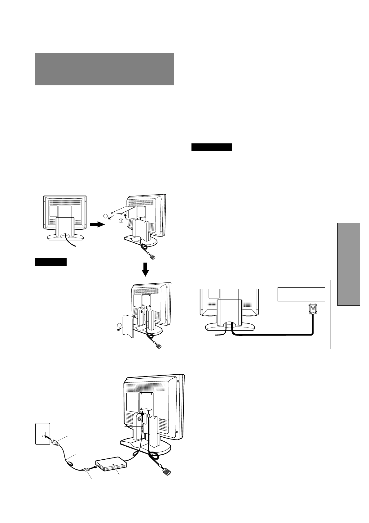
- 3-7 -
DEUTSCH
3
3
INSTALLATION UND
ANSCHLUß
Auf der Rückseite des Monitors befinden sich drei
Anschlüsse: Einer zum Anschluss der
Spannungsversorgung (Gleichspannung, DC) und zwei
für den Anschluß der Video-Eingangssignale.
3.1 Anschluß des Netzkabels
Entfernen Sie die Kabelabdeckung. Stecken Sie den
Gleichspannungsstecker des Netzteils in die dafür
vorgesehene Buchse auf der Rückseite des Monitors und
das eine Ende des Netzkabels in das Netzteil sowie das
andere Ende in eine ordnungsgemäß geerdete
Netzsteckdose. Das Schaltnetzteil des Monitors stellt sich
selbständig auf die Netzspannung ein.
ACHTUNG
Die Stromversorgung dieses
Monitors bleibt auch bei
ausgeschaltetem Gerät aktiv.
Daher sollte sich die
Netzsteckdose in der Nähe des
Gerätes befinden und leicht
zugänglich sein.
Verwenden Sie das externe
Netzteil nicht für andere Geräte,
da dies zur Beschädigung oder
Bränden führen kann.
Wenn Sie den MultiSync
®
LCD
mit seiner weltweiten AC 220-
240V Stromversorgung
betreiben, verwenden Sie ein
Netzkabel, das der
Speisungsspannung der
verwendeten
Wechselstromsteckdose
entspricht. Das verwendete
Netzkabel muß den
Sicherheitsnormen Ihres Landes
entsprechen und gemäß dieser
zugelassen sein.
3.2 Anschluß des Signalkabels
Das beigefügte Signalkabel ist mit einem D-SUB-15P
Stecker für den Anschluß an die VGA-kompatiblen
analogen RGB-Ausgänge lhres PC ausgestattet. Der
Anschluß von Apple Macintosh Computem kann unter
Verwendung des optional erhältlichen Macintosh Adapt-
ers erfolgen.
ANMERKUNG
• Sync-auf-Grün-Signale mit Ausgleichsimpulsen
können nicht mit diesem Monitor verwendet werden.
• Bitte vermeiden Sie die gleichzeitige Verwendung von
Sync-auf-Grün und separaten Synchronisations-
Signalen. Dies Könnte zu einer Störung der Darstellung
führen.
3.2.1 Anschluß an IBM VGA kompatibles System
Bild 5 zeight den Anschluß des Signal Kabels an die VGA-
Grafikkarte eines IBM
®
PS/2 oder jedes andere VGA-
kompatible System.
1. Schalten Sie den Monitor und den PC aus.
2. Schließen Sie das Computerende des Signal Kabel
an die 15-polige Buchse an der VGA-Grafikkarte an.
3. Schalten Sie erst den Monitor, dann den PC ein.
4. Wenn Sie das System verlassen, schalten Sie erst
den Monitor, dann den PC aus.
3
2
<Entfernen der Abdeckungen>
DC Netzlabel
Stecler
Netzkabel
Buchse
AC Adapter
Bild 5
Signal Kabel
Hochauflösende
Grafikkarte
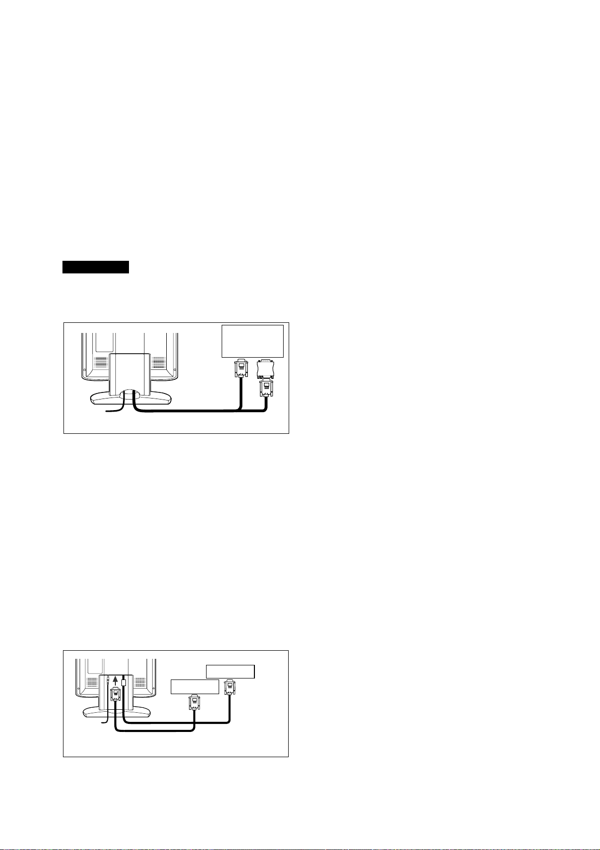
- 3-8 -
3.2.2 Anschluß an Apple Macintosh Computer
Bild 6 zeigt den Anschluß an einen Apple Macintosh unter
Verwendung des mitgelieferten Signalkabels und des
Macintosh-Adapters.
1. Schalten Sie den Monitor und den Rechner aus.
2. Schließen Sie das 15-polige Ende (D-SUB-15P) des
Macintosh Adapters an die 15-polige Buchse an dem
integrierten Macintosh Grafikadapter oder der
Zusatzgrafikkarte an.
3. Verbinden Sie das 15-polige Sub-Miniatur-Ende (D-
SUB-15P) des Macintosh Adapters mit dem Signal
Kabel (P/C).
4. Schalten Sie zuerst den Monitor, dann den Macintosh
ein.
5. Wenn Sie das System verlassen, schalten Sie erst
den Monitor, dann den Macintosh aus.
ANMERKUNG
Falls lhr Apple Macintosh Computer mit einem VGA-
kompatiblen Anschluß ausgestattet ist, entfallen die
Schritte 2 bis 4. Schließen Sie in diesem Fall das
Signalkabel direkt an Anschluß an.
3.2.3 Anschluß an zwei Computer
Bild 7 zeigt den Anschluß der Signalkabel an zwei Com-
puter.
1. Schalten Sie den Monitor und die Computer aus.
2. Schließen Sie das Ende des fest verbundenen
Signalkabels an den 15-poligen Anschluß des einen
Computers an.
3. Zum Anschluß des zweiten Computers benötigen Sie
das erhältliche Signalkabel (Bitte fragen Sie Ihren
Händler). Verbinden Sie das eine Ende des
Signalkabels (15-polig) mit dem Monitor und das andere
Ende mit dem Ausgang der Grafikkarte.
4. Schalten Sie den Monitor ein, und anschließend die
Computer.
5. Nach Benutzung schalten Sie zuerst den Monitor aus,
und anschließend die Computer.
Macintosh Adapter
Apple
Macintosh
Computer
Signal Kabel
Bild 6
D-SUB-15P
D-SUB-15P
Erhältliche Signalkabel
Cpmputer
Cpmputer
Bild 7
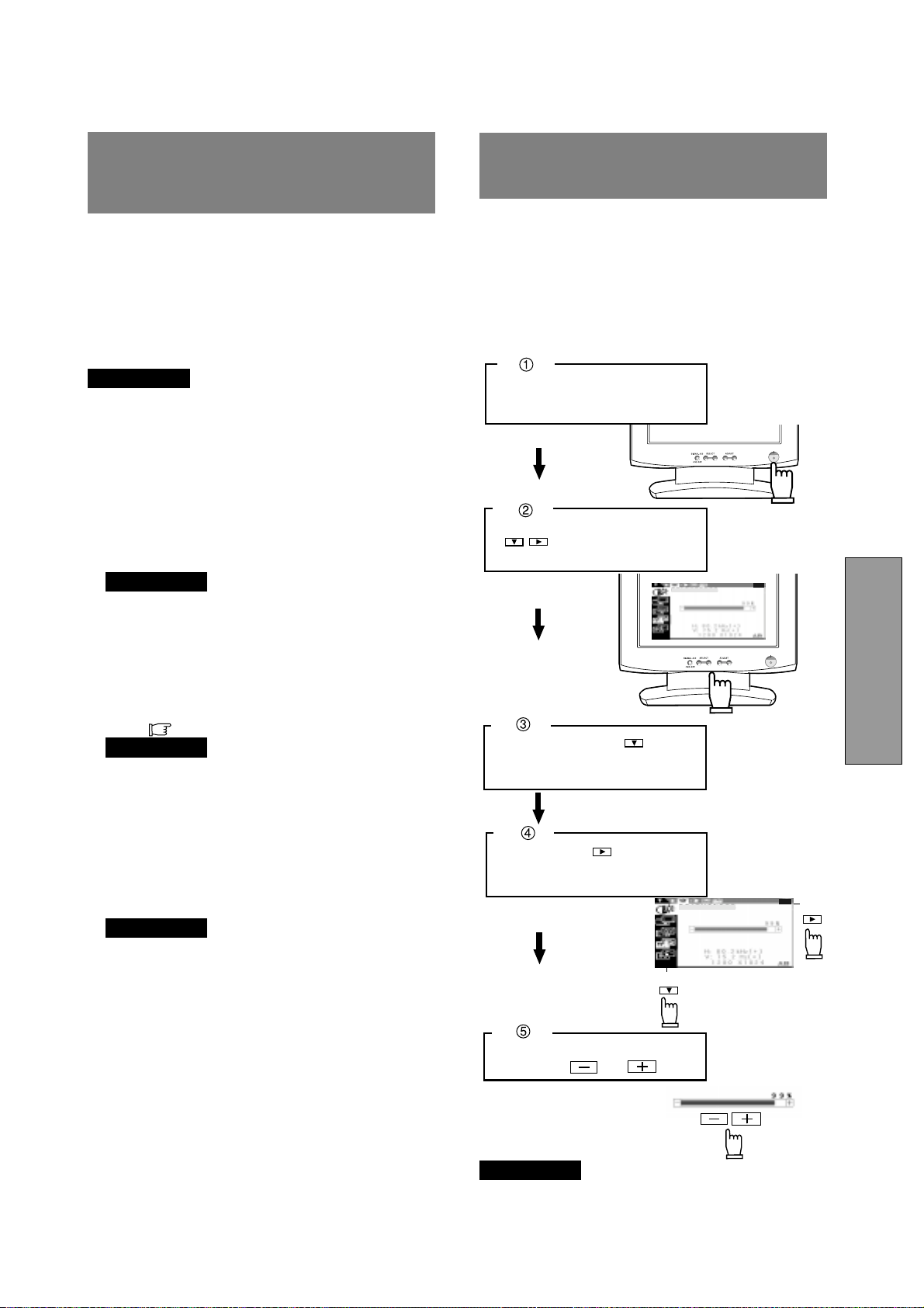
- 3-9 -
DEUTSCH
Einstellen des Monitors
Der Monitor verfügt über ein sogenanntes OSM (On
Screen Manager, Bildschirmmenü), mit dem alle
Einstellugen sehr komfortabel durchgeführt werden
können.
Im folgenden wird Ihnen gezeigt, wie Sie den Monitor mit
Hilfe des OSM einstellen können.
ANMERKUNG
Wird für ca 30 Sekunden keine der Tasten gedrückt, wird
das OSM ausgeblendet.Oder drücken Sie die OSD OFF-
Taste, dann schaltet das OSM sofort ab.
5
4
4
AUTOMATISCHE
EINSTELLFUNKTION
Es gibt zwei Methoden zur Einstellung des Bildschirms:
"AUTOEINSTELLUNG" und "OSM
TM
-Einstellung" (siehe
5. OSM BEDIENUNG). Führen Sie zuerst die
"AUTOEINSTELLUNG"-Funktion aus, und anschließend
falls notwendig die manuelle Einstellung mittels OSM.
Bei Benutzung von "AUTOEINSTELLUNG" werden folgende
Funktionen automatisch eingestellt: "KONTRAST"
"HORIZONTALE BILDLAGE", "VERTIKALE BILDLAGE",
"TAKT", "TAKT-PHASE" und "SCHWARZPEGEL".
ANMERKUNG
• In Verbindung mit einigen Computern kann es sein,
daß die "AUTOEINSTELLUNG"-Funktion nicht korrekt
arbeitet. Führen Sie in diesem Fall eine manuelle
Einstellung mittels des Bildschirmmenus durch.
• Bei Verwendung eines Interlacedsignals mit einer
Auflösung von 1280 Bildpunkten x 1024 Linien, geht
eine Linie am oberen oder unteren Rand verloren.
Dieser Fehler kann durch eine Justierung nicht
behoben werden.
Führen Sie die “AUTOEINSTELLUNG” folgendermaßen durch.
1. Schalten Sie den Computer und den Monitor ein.
ANMERKUNG
Falls Sie das Symbol nicht erkennen können, ändern
Sie "TAKT", bis es erkennbar ist.
Falls Sie das Symbol nicht sehen können, weil das
Bild in vertikaler oder horizontaler Richtung verschoben
ist, stellen Sie bitte "VERTIKALE BILDLAGE" oder
"HORIZONTALE BILDLAGE" mit Hilfe des OSM ein,
bis das Symbol sichtbar ist.
2. Wählen Sie "AUTOEINSTELLUNG" im OSM-Menü
aus. (
S.3-10)
ANMERKUNG
Wenn der Bildschirm einen schwarzen Hintergrund
wie bei der "MS-DOS EINGABEAUFFORDERUNG"
hat, kann es sein, daß "AUTOEINSTELLUNG" nicht
korrekt funktioniert.
3. Drücken Sie die "+" Taste, um "AUTOEINSTELLUNG"
zu starten.
Während "AUTOEINSTELLUNG" läuft, erscheint
"AUTOEINSTELLUNG" auf dem Bildschirm und
verschwindet nach Beendigung wieder. Bis zur
Beendigung dauert es ca 10 Sek.
ANMERKUNG
Wird ein Interlace Signal verwendet, fehlt am oberen
oder unteren Bildschirmrand eine Linie nachdem die
"AUTOEINSTELLUNG" beendet ist. In diesem Fall,
stellen Sie bitte die "VERTIKALE BILDLAGE" über
das OSM ein.
-
+
-
+
Führen Sie die Einstellung mit
den Tasten und durch.
Drücken Sie die Taste, um das
Symbol der Einstellfunktion im
Untermenü zu wählen.
Schalten Sie den Monitor ein.
Drücken Sie irgendeine Taste
( ) auf dem Bedienfeld,
um das OSM anzuzeigen.
Drücken Sie die Taste , um das
Gruppensymbol (linke Spalte) in
Hauptmenü auszuwählen.
Hauptmenü
Untermenü
HELLIGKEIT
HELLIGKEIT
5 OSM BEDIENUNG
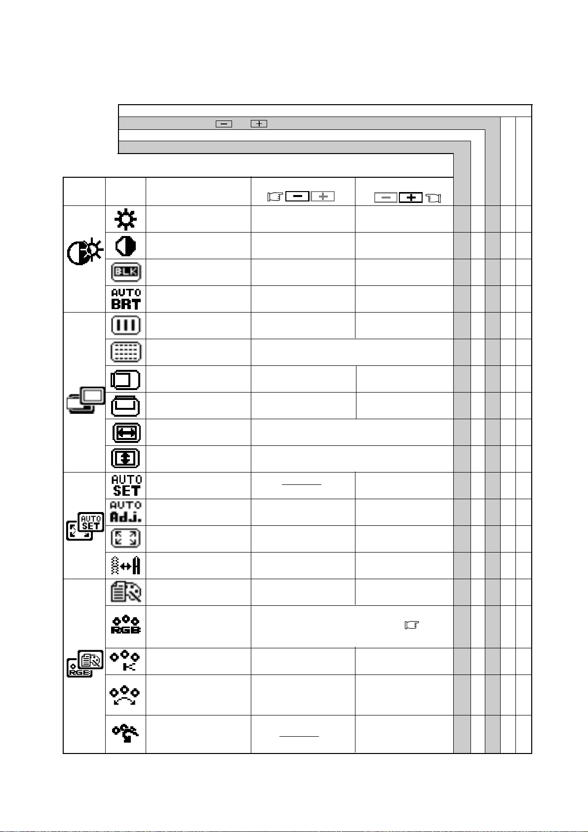
- 3-10 -
Um die normale Bilddarstellung
(1:1) auszuwählen.
Um die erweiterte
Bilddarstellung auszuwählen.
Um die Bildbreite nach
rechts auszuweiten.
Schaltet die Funktion
“AUTOM.-KORREKTUR” ein.
Werksseitige Voreinstellungen
Benutzereinstellungen
5.1 Einstellfunktionen
Drücken sie gleichzeitig die und Taste, um die werksseitig voreingestellten Werte wiederherzustellen.
Benutzen Sie “WERKSEINSTELLUNG”, um diese Funktionen auf die werksseitigen Voreinstellungen zur
ü
ckzusetzen.
Diese Einstellungen sind unabhängig vom verwendeten Timing und ändern sich beim Wechsel des Videosignals nicht.
Diese Werte müssen für jedes Timing einzeln eingestellt werden.
Gruppen
symbol
Drücken Sie die Minus Taste:
Drúcken Sie die Plus Taste:
Symbol
Funktion
Um die Helligkeit zu
verringern.
Um die Helligkeit zu
erhöhen.
Um den Schwarzpegel
zu verringern.
Um den Schwarzpegel
zu erhöhen.
Um den Kontrast zu
verringern.
Um den Kontrast zu
erhöhen.
Um die Farbtemperatur
zu verringern.
Um die Farbtemperatur
zu erhöhen.
Um Bildbreite nach
links zu verringern.
Um das Bild nach links
zu verschieben.
Um das Bild nach
rechts zu verschieben.
Um das Bild nach unten
zu verschieben.
Um das Bild nach
oben zu verschieben.
Um das Rauschen (Schnee) des Bildes zu
verringern.
Führt “AUTOEIN-
STELLUNG” durch.
Wählt den Anzeige-
modus “TEXT” aus.
Wählt den Anzeige-
modus “GRAFIK” aus.
Schaltet die Funktion
“AUTOM.-KORREKTUR” aus.
Schaltet die Funktion
AUTOM. HELLIGKEIT aus.
Schaltet die Funktion
AUTOM. HELLIGKEIT ein.
Um die Schäfe zu
verringern.
Um die Schärfe zu
erhöhen.
Die Farbe des Bildschirms
wird auf die Farbe des “-”
Symbols an der linken Seite
des Balkens eingestellt.
Die Farbe des Bildschirms
wird auf die Farbe des “+”
Symbols an der rechten Seite
des Balkens eingestellt.
Um die Höhe des Bildes einzustellen.
Um die Breite des Bildes einzustellen.
Wählen Sie die gewünschte Farbwiedergabe (sRGB,
VIDEO, NATIVE oder BENUTZER) aus
( S.3-4)
Um die Farbtemperatur und
die Farbsteuerung auf die
werksseitigen Voreinstellungen
zurückzusetzen.
sRGB, VIDEO, NATIVE: Nicht einstellbar.
HELLIGKEIT ○○○○
KONTRAST ○○○○
SCHWARZPEGEL ○○○○
AUTOM. HELLIGKEIT ○○○
TAKT ○○
TAKTPHASE ○○
HORIZONTALE BILDLAGE
○○
VERTIKALE BILDLAGE ○○
AUFLÖSUNG H
○○
AUFLÖSUNG V
○○
AUTOEINSTELLUNG ‑‑‑‑‑
AUTOM.-KORREKTUR ○○
VOLLBILD ○○
SCHÄRFE ○○○
ANZEIGEMODUS ○○○
FARBE ○○○
FARBTEMPERATUR ○○○○
FARBSTEUERUNG ○○○○
FARBRÜCKSTELLUNG ‑ ‑‑‑
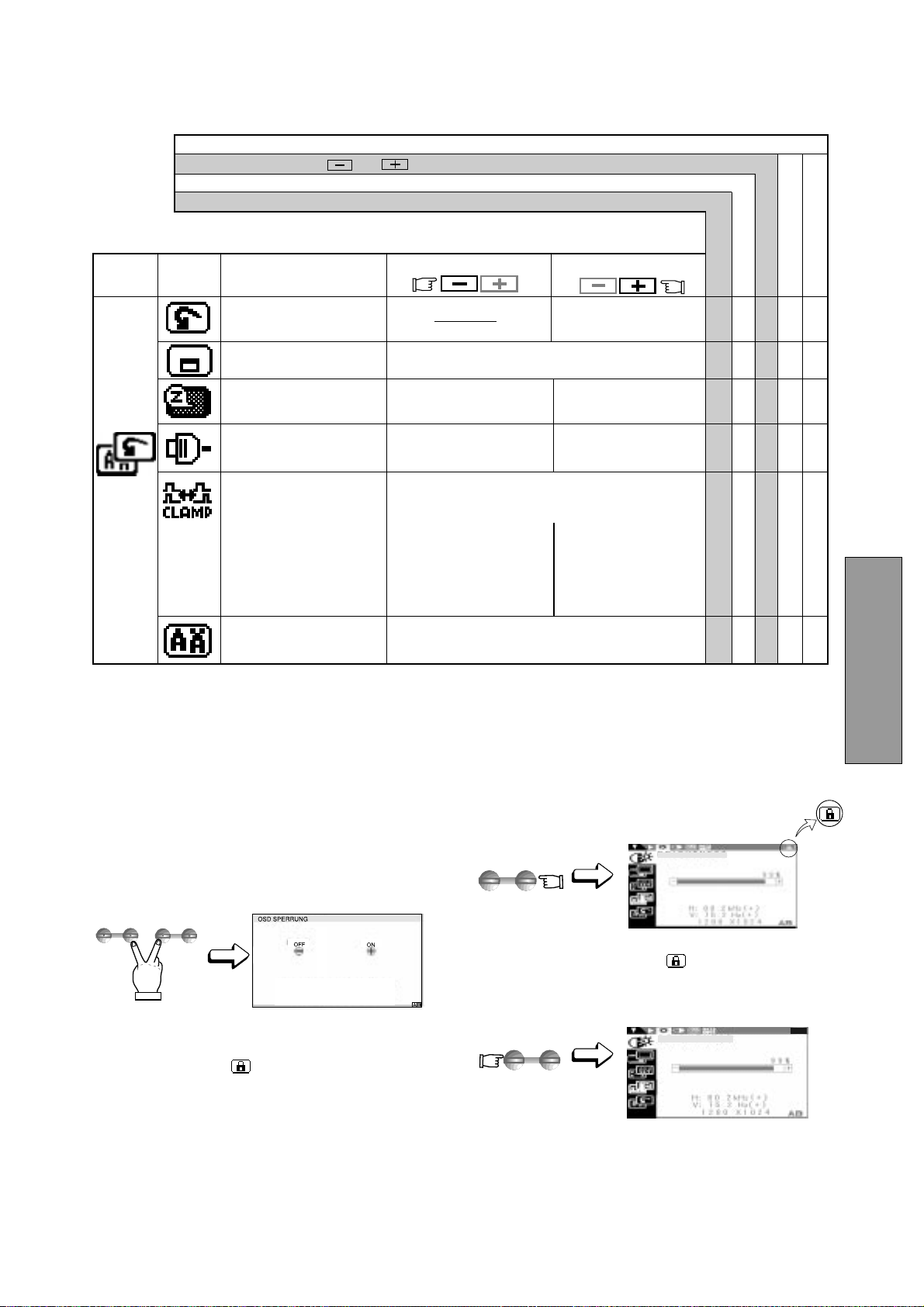
- 3-11 -
DEUTSCH
ADJUST
-
+
ADJUST
-
+
SELECT
ADJUST
Verhindert einen übermäßig grünen oder weißen
Hintergrund, der bei Sync-On-Green und einem
gleichzeitigen externen Synchronsignal auftreten kann.
Um die Schwarz-
schulterklemmung auf die
vordere Schwarzschulter
zu setzen.
Um die Schwarz-
schulterklemmung auf die
hintere Schwarzschulter
zu setzen. Kann bei
Anschluß eines älteren
Macintosh-Computers
notwendig sein.
Um die automatische
Eingangswahl auszuschalten.
Um die automatische
Eingangswahl einzuschalten.
Setzt die Einstellungen
auf die Werksseitigen
Voreinstellungen zurück.
Zur Auswahl einer von 5 möglichen
Positionen des OSD.
Um das Powermanagement
einzuschalten.
Um das Powermanagement
auszuwählen.
Wählt die OSM Sprache aus.
ENG......Englisch, FRA......Französisch, ESP......Spanisch,
ITA......Italienisch, GER......Deutsch, JPN......Japanisch
Werksseitige Voreinstellungen
Benutzereinstellungen
Benutzen Sie “WERKSEINSTELLUNG”, um diese Funktionen auf die werksseitigen Voreinstellungen zur
ü
ckzusetzen.
Diese Einstellungen sind unabhängig vom verwendeten Timing und ändern sich beim Wechsel des Videosignals nicht.
Diese Werte müssen für jedes Timing einzeln eingestellt werden.
Gruppen
symbol
Drücken Sie die Minus Taste:
Symbol
Drücken Sie die Plus Taste:
Funktion
SCHWARZWERT-
KLEMMUNG
HELLIGKEIT
HELLIGKEIT
5.2 Benutzung der OSD Sperrung
1. Durch gleichzeitiges Betätigen der rechten
“AUSWAHL” Taste und der “-” Taste, erscheint das
Menü “OSD SPERRUNG”.
2. Drücken Sie die “+” Taste, um das OSM
TM
zu sperren.
Während der OSM-Sperrung erscheint oben rechts im
OSM das Symbol “
”. Nur die “HELLIGKEIT” kann
jetzt eingestellt werden.
Außerdem ist die Taste “A/B signal change/OSD OFF”
weiterhin in Funktion.
Drücken sie gleichzeitig die und Taste, um die werksseitig voreingestellten Werte wiederherzustellen.
3. Drücken Sie die “-” Taste um die Sperrung des OSM
aufzuheben. Das Symbol “
” verschwindet aus der
OSM-Anzeige. SŠmtliche Funktionen des OSM können
wieder verwendet werden.
WERKSEINSTELLUNG ‑ ‑‑‑
OSD POSITION ○○○
ENERGIESPARFUNKTION
○○○
AUTOM.-EINGANGSWAHL
○○○
○○○
SPRACHE ○
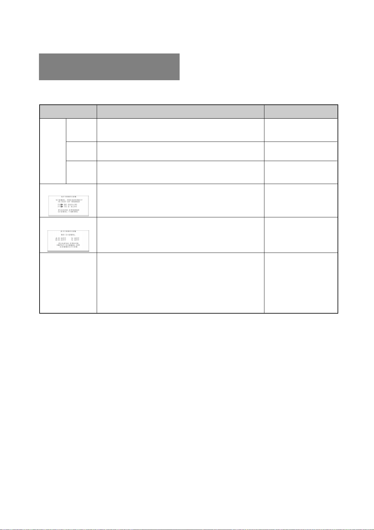
- 3-12 -
6
6
STÖRUNGSSUCHE
Bevor Sie sich an den Product Support wenden, überprüfen
Sie bitte die unten genannten Anschlüsse und Einstellungen.
Sollten Sie kein Standardsignal verwenden, prüfen Sie
bitte, ob das Signal Ihres Computers mit der entsprechenden
Spezifikation in ’Kapitel 7 SPEZIFIKATIONEN.
PROBLEM
POSITION
KONTROLLE
Kein
Bild
LED an
(Grün)
LED aus
LED an
(Bernstein)
Das Bild fehlt, ist
nicht zentriert, ist zu
klein oder zu groß.
Auf dem Bildschirm erscheint
folgende Meldung.
Auf dem Bildschirm
erscheint folgende Meldung.
• Kontrast- und Helligkeitsregler in minimaler Position?
• Netzschalter eingeschaltet?
• Netzkabel korrekt angeschlossen?
• Signalkabel angeschlossen?
• Netzschalter des Computers eingeschaltet?
• Energiesparfunktion ist aktiv?
• Eingangssignalfrequenz außerhalb des zulässigen Bereichs?
• Die Auflösung befindet sich außerhalb des zulässigen Bereichs.
• Signalkabel angeschlossen?
• Netzschalter des Computers eingeschaltet?
• Energiesparfunktion ist aktiv?
• Bei User Timing, AUFLÖSUNG, TAKT, TAKTPHASE,
HORIZONTALE BILDLAGE und VERTIKALE BILDLAGE einstellen.
• Im Einzelfall kann es vorkommen, daß der Monitor aufgrund des
verwendeten Signaltimings keine Vollbilddarstellung bietet.
Wechseln Sie in diesem Fall die Auflösung oder die
Vertikalfrequenz des Signals.
• Um die Speicherung der geänderten Werte sicherzustellen,
warten Sie einige Sekunden bevor Sie das Eingangsignal
wechseln oder den Monitor ausschalten.
• Vorderseite
• Vorderseite
• Rückseite
• Rückseite
• Computer
• Spezifikation des
Grafikadapters und
Monitors prüfen.
• Rückseite
• Computer
• Vorderseite (OSM
TM
)
• Vorderseite (OSM)
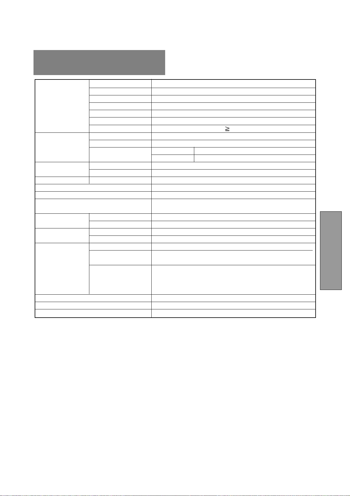
- 3-13 -
DEUTSCH
7
7 SPEZIFIKATIONEN
LCD Bildschirm 46cm/18.1" Color TFT Farbbildschirm
Bildschirm Active Matrix
Auflösung 1280 Punkte x 1024 Linien
Punktabstand 0.28mm
Farbstufen R, G, B vertikale Streifenart
Frontglasbeschichtung Antireflektierend, hartbeschichtet
Betrachtungswinkel ±80°(Horizontal / Vertical) CR 5
Video 0.7Vp-p analog RGB
Synchronisation Sync-on-Green oder separate H-, V- oder Composite Sync.
Eingangsimpedanz Video 75 Ω
Synchronisation 2.2k Ω
FREQUENZ- Horizontal 24.0 - 80.0kHz
BEREICH Vertikal 50.0 - 86.0Hz
BILDFLÄCHE H x V 359mm x 287.2mm
Anzahl der darstellbaren Farben 16.77 Millionen Farben
HELLIGKEIT(bei voller Weißfläche) 200 cd/m
2
(Typ.)
EINGANGSANSCHLUß D-SUB-15P (Einmal fest angeschlossenes Signalkabel, einmal
Buchse hinter der Abdeckklappe)
BETRIEBS- Temperature 5 ‑ 35°C
BEDINGUNGEN Feuchtigkeit 10 ‑ 90%rel. Luftf.(nicht kondensierend)
NETZSPANNUNG Farbmonitor 55W max.
AC-Adapater EINGANG:AC100~240V±10%, 50/60Hz AUSGANG: DC15V
Sicherheit UL1950 (UL), CSA C22.2 No.950 (C-UL), EN60950(TÜV-GS)
EMC FCC Klasse-B, DOC Klasse-B, EN55022 Klasse-B, EN50082-1
ZULASSUNGEN/ VCCI Klasse-B, EN61000-3-3
PRÜFZEICHEN Andere CE-Marking, MPR-II,TCO ’99,
ISO 9241-3, ISO 9241-7, ISO 9241-8(TÜV-GS)
International E
NERGY STAR
Energy 2000 Labeling Award
(B)18.1" x (H)18.9" x (T)8.7"/ (B)460mm x (H)481mm x (T)220mm
8.2kg (18.1lbs.)(exkl.Netzadapter und Kabel)
DREH-/KIPPFUSS -5° ~ +35° Kippwinkel ±45° Drehwinkel
GEHÄUSE
LCD BILDSCHIRM
EINGANGSSIGNAL
GEWICHT

- 3-14 -
BESCHRÄNKTE
GEWÄHRLEISTUNG
NEC-Mitsubishi (nachstehend als “NEC-MITSUBISHI”
bezeichnet) garantiert hiermit, daß dieses Produkt keinerlei
Material- und Verarbeitungsfehler aufweist, und verpflichtet
sich unter den nachstehenden Bedingungen dazu,
innerhalb eines Zeitraums von drei (3) Jahren nach dem
Datum des ersten Erwerbs durch einen Verbraucher
jedweden Teil des gegenständlichen Produkts, der sich
als defekt erweist, (nach alleinigem Ermessen von NEC-
MITSUBISHI) entweder zu reparieren oder zu ersetzen.
Auf Ersatzteile werden neunzig (90) Tage Garantie
gewährt. Die als Ersatz zur Verfügung gestellten Teile und
Einheiten, bei denen es sich um neue oder um gebrauchte,
wiederinstandgesetzte Komponenten handeln kann,
werden bezüglich ihrer technischen Daten den
ursprünglichen Teilen oder Einheiten entsprechen.
Diese Garantie gewährt Ihnen bestimmte Rechte. Darüber
hinaus haben Sie möglicherweise weitere Rechte, die
sich jedoch von Bundesstaat zu Bundesstaat
unterscheiden. Diese Garantie beschränkt sich auf den
ursprünglichen Käufer des Produkts und ist nicht
übertragbar. Sie erstreckt sich lediglich auf Komponenten,
die von NEC-MITSUBISHI geliefert wurden. Service, der
aufgrund von Komponenten erforderlich wird, die von
Dritten geliefert wurden, ist von der gegenwärtigen Garantie
ausgeschlossen. Um unter die gegenwärtige Garantie zu
fallen, muß das Produkt vom ursprünglichen Käufer in den
USA oder in Kanada erworben worden sein. Diese Garantie
erstreckt sich nur auf von NEC-MITSUBISHI in den USA
oder in Kanada vertriebene Produkte. Außerhalb der USA
bzw. Kanadas werden keine Garantieleistungen erbracht.
NEC-MITSUBISHI wird einen Kaufnachweis fordern, um
das Kaufdatum zu überprüfen. Als Kaufnachweis ist eine
Originalrechnung oder -quittung erforderlich, auf der Name
und die Anschrift des Verkäufers und des Käufers sowie
die Seriennummer des Produkts vermerkt sind.
Um Garantieleistungen unter der vorliegenden Garantie
in Anspruch zu nehmen, sind Sie verpflichtet, das Produkt
entweder in der Originalverpackung oder einer
gleichwertigen Art von Verpackung, die gleichwertigen
Schutz bietet, auf eigene Kosten an den lizenzierten
Händler, bei dem Sie das Produkt erworben haben, oder
an jede sonstige von NEC-MITSUBISHI genehmigte
Einrichtung zu senden (Postgebühren sind im voraus zu
entrichten) oder liefern zu lassen. Produkte dürfen nur
nach vorheriger Genehmigung zu Servicezwecken an
NEC-MITSUBISHI übermittelt werden. Diese
Genehmigung ist unter der Telefonnummer 1-800-632-
4662 einzuholen. Das betreffende Produkt darf zuvor
lediglich von Serviceeinrichtungen, die von NEC-
MITSUBISHI zur Erbringung derartiger Leistungen
autorisiert wurden, verändert, repariert oder gewartet
worden sein. Die Seriennummer des Produkts darf nicht
geändert oder entfernt worden sein.
Produkte, die dazu verwendet wurden, Standbilder über
längere Zeiträume anzuzeigen, und die dadurch einen
Bildschatten (Nachbildwirkung) erlitten haben, sowie
Geräte die durch Unfälle, Mißbrauch oder unsachgemäße
Verwendung geschädigt oder entgegen der im
Benutzerhandbuch enthaltenen Anweisungen verwendet
wurden, sind von der vorliegenden Garantie
ausgeschlossen. Jedwede derartigen Umstände machen
die vorliegende Garantie null und nichtig.
NEC-MITSUBISHI ÜBERNIMMT ÜBER DIE
OBENGENANNTE HAFTUNG HINAUS KEINERLEI
HAFTUNG FÜR DIREKTE ODER INDIREKTE SCHÄDEN,
BEGLEIT- ODER FOLGESCHÄDEN ODER JEGLICHE
SONSTIGE ART VON SCHÄDEN, DIE AUF DEN
GEBRAUCH JEDWEDEN PRODUKTS VON NEC-
MITSUBISHI ZURÜCKZUFÜHREN SIND. DIESE
GARANTIE ERSETZT SÄMTLICHE SONSTIGEN
AUSDRÜCKLICHEN ODER IMPLIZITEN GARANTIEN.
DIES SCHLIESST UNTER ANDEREN DIE IMPLIZITE
GARANTIE DER VERMARKTBARKEIT ODER DER
EIGNUNG FÜR EINEN BESTIMMTEN ZWECK MIT EIN.
IN EINIGEN BUNDESSTAATEN IST DER AUSSCHLUSS
IMPLIZITER GARANTIEN ODER DIE BESCHRÄNKUNG
ODER DER AUSSCHLUSS DER HAFTUNG FÜR
BEGLEIT- ODER FOLGESCHÄDEN NICHT ZULÄSSIG,
D.H. DIE OBENGENANNTEN AUSSCHLÜSSE ODER
BESCHRÄNKUNGEN GELTEN FÜR SIE UNTER
UMSTÄNDEN NICHT.
Die Gewährleistung für dieses Produkt wird gemäß der
Bestimmungen der vorliegenden beschränkten
Gewährleistung übernommen. Die Verbraucher werden
hiermit darauf aufmerksam gemacht, daß die Leistung
des Produkts von der Systemkonfiguration, der Software,
der Anwendung, den Kundendaten und der Steuerung
des Systems seitens des Bedieners sowie von anderen
Faktoren beeinflußt wird. NEC-MITSUBISHI-Produkte
gelten als mit vielen Systemen kompatibel, doch können
spezifische funktionelle Anwendungen des Produkts
seitens des Käufers variieren. Deshalb muß die Eignung
eines Produktes für einen spezifischen Zweck oder eine
spezifische Anwendung vom Käufer festgestellt werden
und wird von NEC-MITSUBISHI nicht gewährleistet.
Den Namen der nächstgelegenen lizenzierten NEC-
MITSUBISHI-Servicestelle erfahren Sie bei NEC-
MITSUBISHI unter der Nummer 1-800-632-4662.