Loading ...
Loading ...
Loading ...
10
bromic.com/heating-au
HEATING INSTALLATION INSTRUCTIONS CONTINUED...
b
d
f
e
g
h
i
c
230 / 9.1 "
870 / 34.2"
a
b
d
f
e
g
h
i
c
9.1”
35.2”
a
b
d
f
e
g
h
i
c
230 / 9.1 "
870 / 34.2"
a
b
d
f
e
g
h
i
c
9.1”
35.2”
a
b
d
f
e
g
h
i
c
230 / 9.1 "
870 / 34.2"
a
b
d
f
e
g
h
i
c
9.1”
35.2”
a
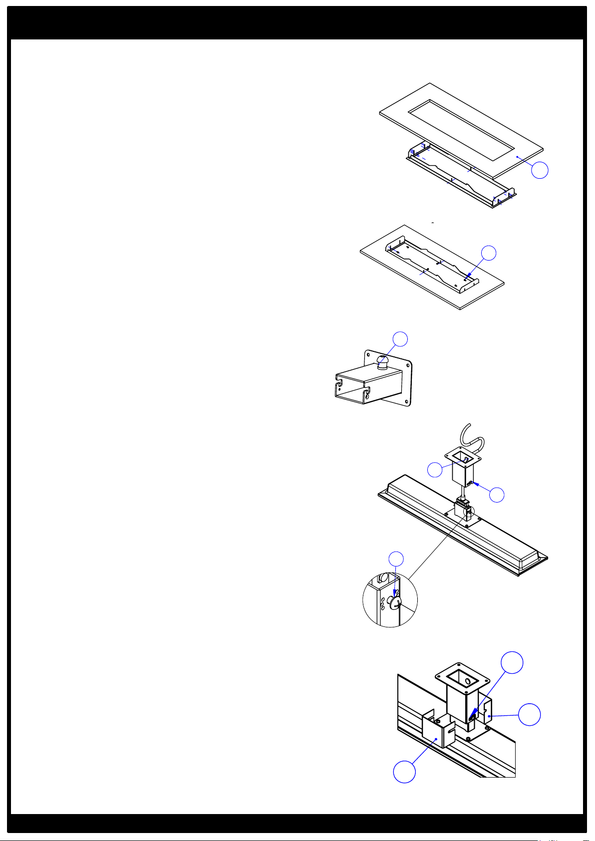
1. Prepare ceiling cut-out with dimensions from images on P.9
to fit ceiling recess frame (a). Heater must be installed with
heater surface at least 2400mm above the floor level, with
500mm clearance to the nearest wall on all sides of the heater.
Minimum distances to combustibles within cavity must be
according to only one of the two options shown.
2. From below, bring ceiling frame up and into ceiling cutout.
Fasten ceiling frame into cut-out at both ends and centre using
appropriate screws (b). Which locator hole to use is dictated
by the thickness of the ceiling surface. The fastening screws
must be inserted into a strong material that can easily support
the weight of the heater. Your installation may require re-
enforcing before the frame can be safely installed.
3. Unscrew and remove plug-in wall bracket. Attach extra
supplied cable gland into the same hole from the outside of
the bracket. Fasten in place with metal cable gland nut from
inside the bracket (c).
4. Feed heater power cable through cable gland from inside of
wall bracket (d).
5. Ensure M6x14mm screws are inserted into either side of
heater bracket with 6mm of the threaded shaft exposed under
the screw head. (e).
6. Insert heater bracket into mounting bracket by hooking M6
screws into place in mounting slots (f).
7. Fix heater to bracket in straight position using M4x10mm
positioning screws on either side of mounting bracket (g).
Ensure M6 screws are sitting fully in the mounting slots (as if
the heater were hanging from the wall bracket).
8. Fit the smaller, straight cover over the heater bracket so
that the slots pass over the shafts of the M6x14mm mounting
screws (h). Fit the larger cover over the smaller cover in the
same way from the opposite side of the bracket (i).
9. Tighten mounting screws firmly, ensuring covers fit snugly
against the bracket on all sides (j).
10. Firmly tighten cable gland in wall bracket so that cable
does not move when pulled.
b
d
f
e
g
h
i
c
230 / 9.1 "
870 / 34.2"
a
b
d
f
e
g
h
i
c
9.1”
35.2”
a
b
d
f
e
g
h
i
c
a
b
d
f
e
g
h
i
c
9.1”
35.2”
a
Loading ...
Loading ...