Loading ...
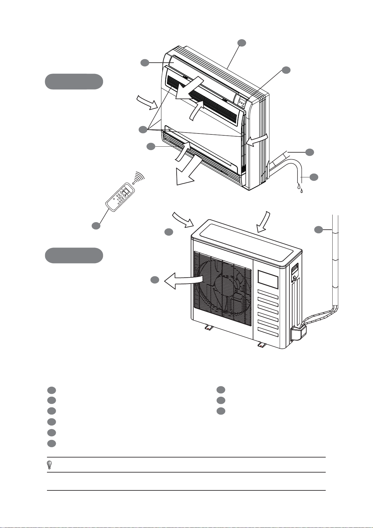
INDOOR UNIT
OUTDOOR UNIT
1
2
3
4
5
6
7
8
9
Display Panel
Connecting Pipe
Air Inlet
Drain Pipe
Air Outlet
Installation Section
Remote Controller
Fig.1
All graphics in this manual are for explanatory purposes only. There may be slight differences from the air
conditioner that you purchased (dependent on model). The actual shape shall prevail.
NOTE
Air Flow Louver (at Air Outlet)
Air Inlet (and Air Filter within)
INDOOR UNIT
OUTDOOR UNIT
7
8
1
9
6
7
1
3
4
2
5
Loading ...
Loading ...
Loading ...