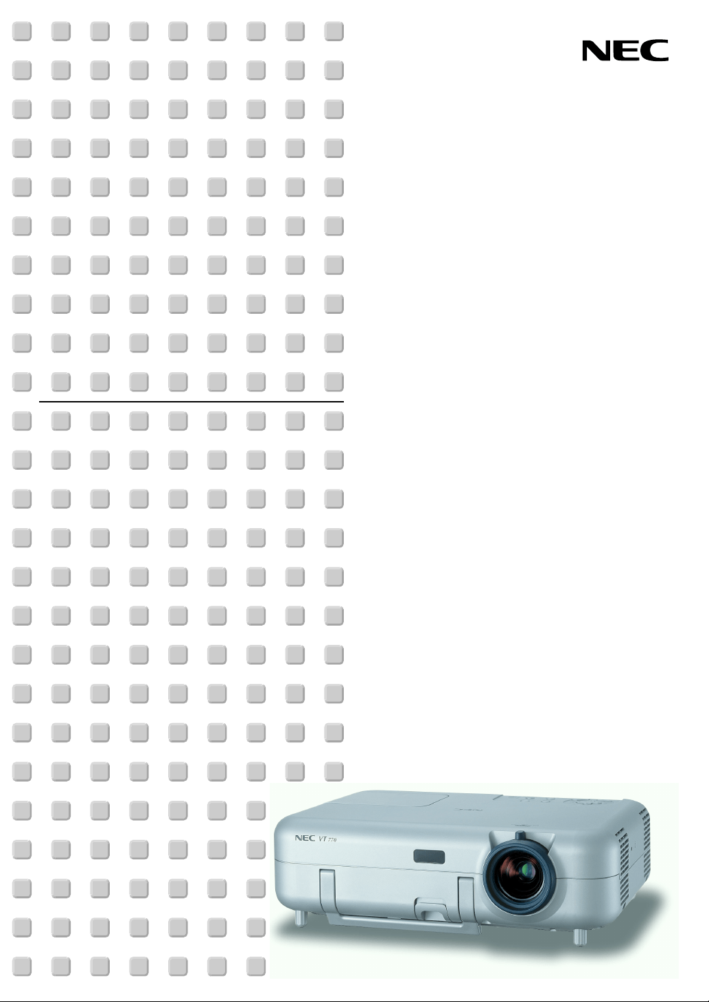
Portable Projector
VT770
User’s Manual
2
Important Information
Safety Cautions
Precautions
Please read this manual carefully before using your NEC VT770 Projector and keep the manual handy for future
reference. Your serial number is located on the bottom of your projector. Record it here:
CAUTION
To turn off main power, be sure to remove the plug from power outlet.
The power outlet socket should be installed as near to the equipment as possible, and should be easily
accessible.
CAUTION
TO PREVENT SHOCK, DO NOT OPEN THE CABINET.
NO USER-SERVICEABLE PARTS INSIDE.
REFER SERVICING TO QUALIFIED NEC SERVICE PERSONNEL.
This symbol warns the user that uninsulated voltage within the unit may be sufficient to cause electrical
shock. Therefore, it is dangerous to make any kind of contact with any part inside of the unit.
This symbol alerts the user that important information concerning the operation and maintenance of this
unit has been provided.
The information should be read carefully to avoid problems.
WARNING: TO PREVENT FIRE OR SHOCK, DO NOT EXPOSE THIS UNIT TO RAIN OR MOISTURE.
DO NOT USE THIS UNIT’S PLUG WITH AN EXTENSION CORD OR IN AN OUTLET UNLESS ALL THREE
PRONGS CAN BE FULLY INSERTED.
DO NOT OPEN THE CABINET. THERE ARE HIGH-VOLTAGE COMPONENTS INSIDE. ALL SERVICING MUST
BE DONE BY QUALIFIED NEC SERVICE PERSONNEL.
DOC Compliance Notice
This Class B digital apparatus meets all requirements of the Canadian Interference-Causing Equipment Regulations.
Acoustic Noise Information Ordinance-3. GSGV:
The sound pressure level is less than 70 dB (A) according to ISO 3744 or ISO 7779.
CAUTION
•Avoid displaying stationary images for a prolonged period of time.
Doing so can result in these images being temporarily sustained on the surface of the LCD panel.
If this should happen, continue to use your projector. The static background from previous images will disap-
pear.
• Do not put the projector on its side when the lamp is turned on.
Doing so may cause damage to the projector.
Copyright
©
2003 by NEC Viewtechnology, Ltd.
WARNING TO CALIFORNIA RESIDENTS:
Handling the cables supplied with this product, will expose you to lead, a chemical known to the State of California
to cause birth defects or other reproductive harm. Wash hands after handling.

3
Important Information
RF Interference
WARNING
The Federal Communications Commission does not allow any modifications or changes to the unit EXCEPT those
specified by NEC Soluctions (America), Inc. in this manual. Failure to comply with this government regulation could
void your right to operate this equipment. This equipment has been tested and found to comply with the limits for a
Class B digital device, pursuant to Part 15 of the FCC Rules. These limits are designed to provide reasonable
protection against harmful interference in a residential installation. This equipment generates, uses, and can radi-
ate radio frequency energy and, if not installed and used in accordance with the instructions, may cause harmful
interference to radio communications. However, there is no guarantee that interference will not occur in a particular
installation.
If this equipment does cause harmful interference to radio or television reception, which can be determined by
turning the equipment off and on, the user is encouraged to try to correct
the interference by one or more of the following measures:
• Reorient or relocate the receiving antenna.
• Increase the separation between the equipment and receiver.
• Connect the equipment into an outlet on a circuit different from that to which the receiver is connected.
• Consult the dealer or an experienced radio / TV technician for help.
In UK, a BS approved power cable with moulded plug has a Black (five Amps) fuse installed for use with this equip-
ment. If a power cable is not supplied with this equipment please contact your supplier.
Important Safeguards
These safety instructions are to ensure the long life of your projector and to prevent fire and shock. Please read them
carefully and heed all warnings.
Installation
1. For best results, use your projector in a darkened room.
2. Place the projector on a flat, level surface in a dry area away from dust and moisture.
3. Do not place your projector in direct sunlight, near heaters or heat radiating appliances.
4. Exposure to direct sunlight, smoke or steam can harm internal components.
5. Handle your projector carefully. Dropping or jarring can damage internal components.
6. Do not place heavy objects on top of the projector.
7. If you wish to have the projector installed on the ceiling:
a. Do not attempt to install the projector yourself.
b. The projector must be installed by qualified technicians in order to ensure proper operation and reduce the
risk of bodily injury.
c. In addition, the ceiling must be strong enough to support the projector and the installation must be in accor-
dance with any local building codes.
d. Please consult your dealer for more information.

4
Important Information
Fire and Shock Precautions
1. Ensure that there is sufficient ventilation and that vents are unobstructed to prevent the build-up of heat inside
your projector. Allow at least 4 inches (10 cm) of space between your projector and a wall.
2. Prevent foreign objects such as paper clips and bits of paper from falling into your projector.
Do not attempt to retrieve any objects that might fall into your projector.
Do not insert any metal objects such as a wire or screwdriver into your projector. If something should fall into
your projector, disconnect it immediately and have the object removed by a qualified NEC service personnel.
3. Do not place any liquids on top of your projector.
4. Do not look into the lens while the projector is on. Serious damage to your eyes could result.
5. Keep any items such as magnifying glass out of the light path of the projector. The light being projected from the
lens is extensive, therefore any kind of abnormal objects that can redirect light coming out of the lens, can
cause unpredictable outcome such as fire or injury to the eyes.
6. Do not cover the lens with the supplied lens cap or equivalent while the projector is on. Doing so can lead to
melting of the cap and possibly burning your hands due to the heat emitted from the light output.
7. The projector is designed to operate on a power supply of 100--240 V 50/60 Hz AC. Ensure that your power
supply fits this requirement before attempting to use your projector.
8. Handle the power cable carefully and avoid excessive bending.
A damaged cord can cause electric shock or fire.
9. If the projector is not to be used for an extended period of time, disconnect the plug from the power outlet.
10. Do not touch the power plug during a thunderstorm. Doing so can cause electrical shock or fire.
CAUTION
• Do not try to touch the ventilation outlet on the left side (when seen from the front) as it can become heated
while the projector is turned on.
• Do not use the tilt-foot for purposes other than originally intended.
Misuses such as gripping the tilt-foot or hanging on the wall can cause damage to the projector.
• Do not send the soft carrying case by parcel delivery service or cargo shipment. The projector inside the soft
carrying case could be damaged. (However, it is possible to use it as a carriercase on board.)
• Enable High-Speed Fan mode if you continue to use the projector for consecutive days. (From the menu,
select [Setup] → [Page 4] → [Fan Mode].)
• Do not unplug the power cable from the wall outlet under any one of the following circumstances.
Doing so can cause damage to the projector:
* While the Hour Glass icon appears.
* While the cooling fans are running. (The cooling fans continue to work for 10 seconds after the projector is
turned off).

5
Lamp Replacement
•To replace the lamp, follow all instructions provided on page 107.
• Be sure to replace the lamp when the message “The lamp has reached the end of its usable life.
Please replace the lamp.” appears. If you continue to use the lamp after the lamp has reached the end of
its usable life, the lamp bulb may shatter, and pieces of glass may be scattered in the lamp case. Do not touch
them as the pieces of glass may cause injury.
If this happens, contact your NEC dealer for lamp replacement.
• Allow a minimum of 10 seconds to elapse after turning off the projector.
Then turn off the main power switch, disconnect the power cable and allow 60 minutes to cool the projector
before replacing the lamp.
Important Information

6
Table of Contents
Important Information ........................................................................ 2
1. Introduction ......................................................................................8
What's in the Box? ........................................................................................................ 9
Introduction to the Projector ....................................................................................... 10
Part Names of the Projector ....................................................................................... 12
Carrying the Projector ........................................................................................... 13
Top Features ......................................................................................................... 14
Te r minal Panel Features ....................................................................................... 15
Remote Control Features ........................................................................................... 17
2. Installation and Connections .................................................... 20
Setting Up the Screen and the Projector .................................................................... 21
Selecting a Location.............................................................................................. 21
Throw Distance and Screen Size .......................................................................... 22
Making Connections ................................................................................................... 23
Enabling the computer’s external display .............................................................. 23
Connecting Your PC or Macintosh Computer ........................................................ 23
To connect SCART output (RGB) ......................................................................... 24
Connecting an External Monitor ........................................................................... 25
Connecting Your DVD Player with Component Output .......................................... 26
Connecting Your VCR or Laser Disc Player .......................................................... 27
Connecting the Supplied Power Cable ................................................................. 28
3. Projecting an Image (Basic Operation) ................................. 29
Tu r ning on the Projector ............................................................................................. 30
Selecting a Source ..................................................................................................... 32
Adjusting the Picture Size and Position ...................................................................... 33
Correcting Keystone Distortion ................................................................................... 35
Optimizing RGB Picture Automatically ....................................................................... 37
Tur ning Up or Down Volume ....................................................................................... 37
Tur ning off the Projector ............................................................................................. 38
After Use..................................................................................................................... 38
4. Convenient Features .................................................................... 39
Switching Operation Mode between Computer and Projector.................................... 40
Tur ning Off the Image and Sound ............................................................................... 40
Freezing a Picture....................................................................................................... 40
Using the Pointer ........................................................................................................ 41
Enlarging and Moving a Picture.................................................................................. 41
Getting the On-line Help ............................................................................................. 42
Using a USB Mouse ................................................................................................... 42
Using the Remote Mouse Function ............................................................................ 43
Correcting Horizontal and Vertical Keystone Distortion (Cornerstone) ....................... 44
쐅 Making Freehand Drawings on a Projected Image (ChalkBoard) .............................. 47

7
Table of Contents
쐈
Storing Images Displayed on the Projector on the PC card or USB Memory (Capture)
.......... 48
쐉 Preventing the Unauthorized Use of the Projector ..................................................... 49
씈 Using a USB Memory Device or USB Memory Card Reader ..................................... 54
5. Using the Viewer ........................................................................... 55
Making the Most out of the Viewer Function ............................................................... 56
Operating the Viewer Function from the Projector ...................................................... 58
쐋 Changing Background Logo ....................................................................................... 64
6.
Using Dynamic Image Utility 2.0 on the supplied CD-ROM
................... 65
End User License Agreement.................................................................................... 66
Introduction ................................................................................................................ 67
Operating Environment .............................................................................................. 68
Equipment Connections and Settings ....................................................................... 69
Software Installation .................................................................................................. 69
Starting/Exiting the Software ..................................................................................... 70
Troubleshooting ......................................................................................................... 72
7. Using On-Screen Menu ................................................................ 73
Using the Menus......................................................................................................... 74
Menu tree ................................................................................................................... 75
Menu Elements........................................................................................................... 77
Menu Descriptions & Functions [Adjust] ..................................................................... 78
Menu Descriptions & Functions [Image] ..................................................................... 82
Menu Descriptions & Functions [Setup] ..................................................................... 85
Menu Descriptions & Functions [Information] ........................................................... 100
Menu Descriptions & Functions [Reset] ................................................................... 101
Entry List .................................................................................................................. 102
8. Maintenance ................................................................................. 104
Cleaning the Filters.................................................................................................. 105
Cleaning the Cabinet ............................................................................................... 105
Cleaning the Lens.................................................................................................... 106
Replacing the Lamp and Filters ............................................................................... 107
9. Appendix ........................................................................................ 110
Troubleshooting ....................................................................................................... 111
Specifications .......................................................................................................... 114
Cabinet Dimensions ................................................................................................ 116
Pin Assignments of D-Sub COMPUTER 1/2 Input Connector ................................ 117
Compatible Input Signal List .................................................................................... 118
PC Control Codes and Cable Connection ............................................................... 119
Using Software Keyboard ........................................................................................ 120
TravelCare Guide ..................................................................................................... 121

1
Introduction
○○○○○○○○○○○○○○○○○○○○○○○○○○○○○○○○○○○○○○○○
What's in the Box? ....................................................... 9
Introduction to the Projector ...................................... 10
Part Names of the Projector ...................................... 12
Carrying the Projector .......................................................................................... 13
Top Features ......................................................................................................... 14
Ter minal Panel Features ....................................................................................... 15
Remote Control Features .......................................... 17
9
1. Introduction
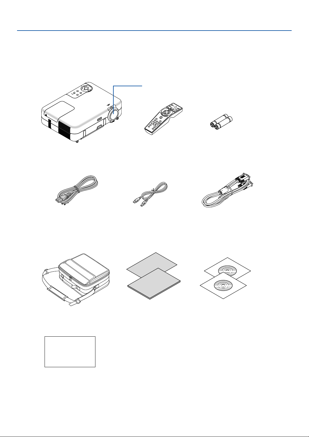
What's in the Box?
Make sure your box contains everything listed. If any pieces are missing, contact your dealer.
Please save the original box and packing materials if you ever need to ship your VT770 Projector.
ZOOM
F
O
C
U
S
3
D
R
E
F
O
R
M
S
O
U
R
C
E
S
E
L
E
C
T
S
T
A
T
U
S
L
A
M
P
P
C
C
A
R
D
P
O
W
E
R
O
N
/
S
T
A
N
D
B
Y
A
U
T
O
A
D
J
U
S
T
M
E
N
U
E
N
T
E
R
C
A
N
C
E
L
P
J
SOURCE
FREEZE
3D-R
EF
O
R
M
ASPECT
POINTER
V
O
L
U
M
E
MAGNIFY
PICTURE
O
F
F
V
I
D
E
O
P
O
W
E
R
O
N
VIEWER
PIC-MUTE
SLIDE
HELP
S
E
L
EC
T
12
S-
VID
E
O
AUTO ADJ.
COMPUTER
COMPONENT
Projector
Lens cap
(24F39571)
Remote control
(7N900451)
Batteries (AA
2)
Power cable
(US: 7N080212)
(EU: 7N080005)
USB cable
(7N520013)
RGB signal cable
(7N520012)
Soft carrying case
(24BS7311)
Quick
Connect
Guide
Important
Information
CD-ROM
• User’s manual (7N950421)
• User Supportware (7N950431)
For North America only
Registration card
Limited warranty
For Europe only
Guarantee policy
(7N8P4101)
(7N8P4111)

10
1. Introduction
Introduction to the Projector
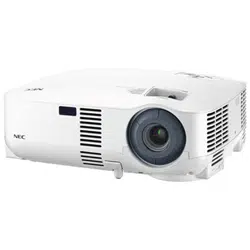
This section introduces you to the VT770 Projector and describes key features and controls.
Congratulations on Your Purchase of the VT770 Projector
The VT770 is a sophisticated three panel LCD XGA projector that produces an enhanced display in less than an 8-
pound (4kg) design. With the VT770 you will be able to project images up to 300” (measured diagonally). Enjoy crisp
and sharp large screen display from your DVD player, VCR, satellite hookup, HDTV source, PC, Workstation or
Macintosh computer (desktop or notebook) and images from your digital camera PC Card, compact flash memory or
USB storage device. The VT770 provides for enhanced security options to help deter projector theft and provides for
full projector control through RS232 support. With input and output flexibility, long lamp life and a full function remote,
the VT770 lets you enjoy larger than life viewing from a compact and easy to setup and use projector.
Features you’ll enjoy on the VT770:
•Automatic vertical keystone correction for fast and easy application setup
• Built-in Wall Color Correction presets provide for adaptive color correction when projecting onto non-white
screen material.
• 3D Reform™ enhanced image technology for increased projector versatility that provides for horizontal, vertical
and diagonal keystone correction (allows for positioning the projector in off center locations in the room and still
get aligned images)
• USB memory or PC card interfaces provide for computerless presentations
• Enhanced smart security settings for password protection, control panel lock, menu lock and PC card protection
key to help prevent unauthorized access, adjustments and theft deterrence
• UXGA compatible, XGA native resolution
•Variable audio out control of external amplified speakers via the projector
• Extensive user adjustable picture and color management settings
• Core technologies – Advanced AccuBlend™, Advanced AutoSense™, VORTEX Technology Plus™ for highest
quality of image display and ease of use
• Display 16:9 or 4:3 aspect ratio information and fill the screen
• HDTV (1080i, 720p) and SDTV (480p, 480i) compatibility
• Digital photo viewer to display larger than life images from your digital cameras PC card, compact flash card or
USB storage device
• Easy set up, use and operation
• Manual zoom and manual focus lens
• Eco-mode™ lamp technology for increased lamp life, reduced energy consumption and overall total cost of
ownership savings
• Wireless remote control operation
• External control via RS232

11
• NEC’s exclusive Advanced AccuBlend intelligent pixel blending technology provides for extremely accurate
image compression and HDTV (1920x1080 and 1280x720) display resolution*.
• Supports most IBM VGA, SVGA, XGA, Macintosh, component signal (YCbCr/YPbPr) or other RGB signals
within a horizontal frequency range of 15 to 100 kHz and a vertical frequency range of 50 to 120 Hz. This
includes NTSC, NTSC4.43, PAL, PAL-M, PAL-N, PAL60 and SECAM standard video signals
NOTE: Composite video standards are as follows:
NTSC: U.S. TV standard for video in U.S. and Canada.
PAL: TV standard used in Western Europe.
PAL-N: TV standard used in Argentine, Paraguay and Uruguay.
PAL-M: TV standard used in Brazil.
PAL60: TV standard used for NTSC playback on PAL TVs.
SECAM: TV standard used in France and Eastern Europe.
NTSC4.43: TV standard used in Middle East countries.
*1 Do not attempt to mount the projector on the ceiling yourself. To ensure proper operation and reduce the risk
of bodily injury a qualified technician must install the projector. In addition, the ceiling must be strong enough
to support the projector and the installation must be in accordance with any local building codes. Please
consult your dealer for more information.
*2 HDTV 1080i (1920 1080) and HDTV 720 p (1280 720) are displayed with NECs Advanced AccuBlend
technology.
Thank you for your purchase of the NEC VT770 projector.
For additional information, please visit our website at:
US: http://www.necvisualsystems.com
Europe: http://www.nec-europe.com/
Global: http:www.nec-pj.com/
1. Introduction
12
1. Introduction
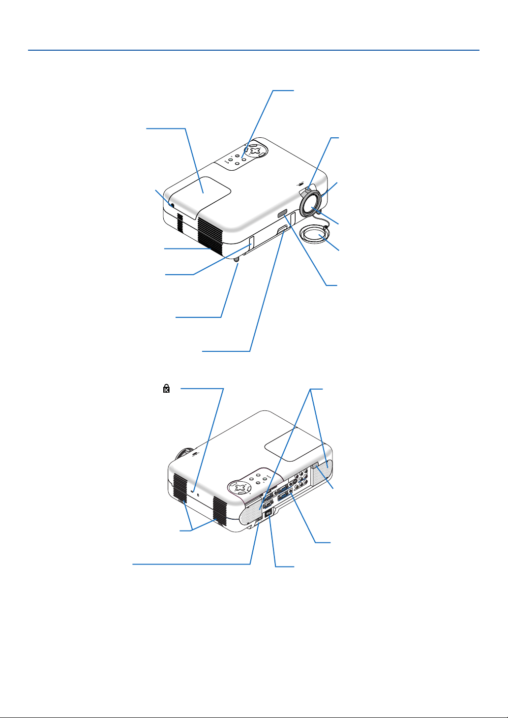
Part Names of the Projector
Z
O
O
M
F
O
C
U
S
3D REFORM
SOURCE
SELECT
STATUS
LAMP
PC CAR
D
POWER
O
N
/
S
T
A
N
D
B
Y
AU
T
O
A
D
JU
S
T
M
E
N
U
E
N
T
E
R
C
A
N
C
E
L
Controls
(See page 14)
Zoom lever
(See page 34)
Focus ring
(See page 34)
Lens
Lens cap
Remote sensor
(See page 97)
Adjustable Tilt Foot Button
(See page 33)
Carrying Handle
Adjustable Tilt Foot
(See page 33)
Ventilation (outlet)
Heated air exhausted from
here.
Lamp Cover Screw
Lamp Cover
(See page 107)
A
C
IN
C
O
M
P
O
N
E
N
T
YC
b
/
P
b
C
r
/
P
r
A
U
D
I
O
A
U
D
I
O
A
U
D
I
O
S
-
V
I
D
E
O
C
O
M
P
U
T
E
R
1
A
U
D
I
O
P
C
C
A
R
D
USB(COMPUTER)
USB(M
OUSE)
M
O
N
I
T
O
R
O
U
T
C
O
M
P
U
T
E
R
2
P
C
C
O
N
T
R
O
L
L
/
M
O
N
O
V
I
D
E
O
R
C
O
M
P
O
N
E
N
T
Y
C
b
/
P
b
C
r
/
P
r
A
U
D
I
O
A
U
D
I
O
L
/
M
O
N
O
R
PC CARD
3D REFORM
SOURCE
STATUS
LAMP
POWER
O
N
/
S
T
A
N
D
B
Y
A
U
T
O
A
D
J
U
S
T
S
E
L
E
C
T
M
E
N
U
E
N
T
E
R
C
A
N
C
E
L
ZOOM
F
O
C
U
S
Ventilation (inlet) / Filter Cover
AC Input
Connect the supplied power cable's
two-pin plug here, and plug the
other end into an active wall outlet.
(See page 28)
Main Power Switch
When you plug the supplied power
cable into an active wall outlet and
turn on the Main Power switch, the
POWER indicator turns orange and
the projector is in standby mode.
(See page 30)
Stereo Speaker
Remote sensor
(See page 97)
Built-in Security Slot ( )*
Ter minal Panel
(See page 15)
* This security slot supports the MicroSaver ® Security System. MicroSaver ® is a registered trademark of
Kensington Microware Inc. The logo is trademarked and owned by Kensington Microware Inc.

13
1. Introduction
Carrying the Projector
Always carry your projector by the handle.
Ensure that the power cable and any other cables con-
necting to video sources are disconnected before mov-
ing the projector.
When moving the projector or when it is not in use, cover
the lens with the lens cap.
ZOOM
F
O
C
U
S
14
1. Introduction
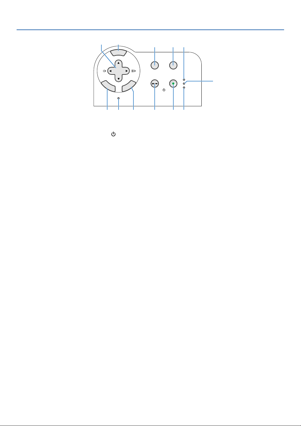
Top Features
SELECT
3D REFORM
SOURCE
STATUS
LAMP
PC CARD
POWER
ON/STAND BY
AUTO ADJUST
M
E
N
U
E
N
T
E
R
C
A
N
C
E
L
3
2
4
17
10 12 11
5
89
6
1. POWER Button (ON / STAND BY) ( )
Use this button to turn the power on and off when the
main power is supplied.
To turn on or off the projector, press and hold this but-
ton for a minimum of two seconds.
2. POWER Indicator
When this indicator is green, the projector is on; when
this indicator is orange, it is in standby mode. See the
Power Indicator section on page 111 for more details.
3. STATUS Indicator
If this light blinks red rapidly, it indicates that an error
has occurred, the lamp cover is not attached properly
or the projector has overheated.
If this light remains orange, it indicates that you have
pressed a cabinet button while the Cabinet Button is
locked. See the Status Indicator section on page 111
for more details.
4. LAMP Indicator
If this light blinks red rapidly, it's warning you that the
lamp has reached the end of its usable life. After this
light appears, replace the lamp as soon as possible
(See page 107). If this is lit green continually, it indi-
cates that the lamp mode is set to Eco. See the Lamp
Indicator section on page 111 for more details.
5. SOURCE Button
Use this button to select a video source such as a PC,
VCR, DVD player or Viewer (PC card).
Press and release this button quickly to display the
Source List.
Each time this button is pressed for a minimum of ONE
second, the input source will change as follows:
Computer1 → Computer2 → Component → Video →
S-Video → Viewer → Entry List → Computer1 → ...
If no input signal is present, the input will be skipped.
6. AUTO ADJ. Button
Use this button to adjust Position-H/V and Pixel Clock/
Phase for an optimal picture (See page 37). Available
for the RGB signal only.
7. 3D REFORM Button
Press this button to enter 3D Reform mode to correct
the keystone (trapezoidal) distortion, and make the
image square. See pages 35 and 44.
8. MENU Button
Displays the menu.
9. SELECT 왖왔왗왘 / Volume Buttons
왖왔 : Use these buttons to select the menu of the
item you wish to adjust.
왗왘 : Use these buttons to change the level of a se-
lected menu item.
A press of the 왘 button executes the selec-
tion. When no menus appear, these buttons
work as a volume control.
When an image is magnified, the SELECT 왖왔왗왘
button moves the image.
10. ENTER Button
Executes your menu selection and activates items
selected from the menu.
11. CANCEL Button
Pressing this button will return to the previous menu.
While you are in the main menu, pressing this button
will close the menu.
12. PC CARD Access Indicator
Lights while accessing a PC card.
15
1. Introduction
COMPONENT
Y Cb/Pb Cr/Pr
AUDIO
AUDIO
AUDIO
AUDIO
L/MONO
S-VIDEO
COMPUTER 1AUDIO
PC CARD
USB(COMPUTER)
USB(MOUSE)
MONITOR OUT
COMPUTER 2
PC CONTROL
R
L/MONOVIDEO R
134
52
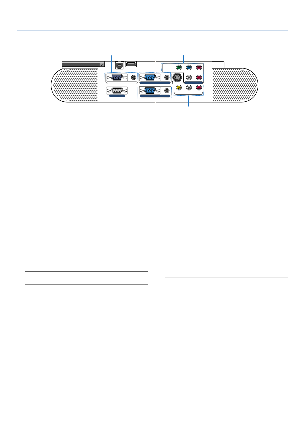
Te r minal Panel Features
1. COMPUTER 1 Input Connector (Mini D-Sub 15 Pin)
Connect your computer or other analog RGB equip-
ment such as IBM compatible or Macintosh comput-
ers. Use the supplied RGB cable to connect to your
computer.
COMPUTER 1 AUDIO Input Mini Jack (Stereo Mini)
This is where you connect the audio output from your
computer when connected to the COMPUTER 1 in-
put. A commercially available audio cable is required.
2.
COMPUTER 2 Input Connector (Mini D-Sub 15 Pin)
Connect your computer or other analog RGB equip-
ment such as IBM compatible or Macintosh comput-
ers. Use the supplied RGB cable to connect to your
computer.
This connector also supports SCART output signal.
The SCART cable is sold separately.
See page 24 for more details.
NOTE: The COMPUTER 2 Input does not support Plug &
Play.
COMPUTER 2 AUDIO Input Mini Jack (Stereo Mini)
This is where you connect the audio output from your
computer when connected to the COMPUTER 2 in-
put. A commercially available audio cable is required.
3. MONITOR OUT Connector (Mini D-Sub 15 Pin)
You can use this connector to loop your computer
image to an external monitor from the COMPUTER
1/2 or component video input source.
This connector also outputs a COMPUTER signal
or component signal in Idle mode.
AUDIO OUT Mini Jack (Stereo Mini)
You can use this jack to output sound from the cur-
rently selected source (COMPUTER 1/2, COMPO-
NENT, VIDEO or S-VIDEO). The current or last dis-
played source's audio will be sent to the audio output
even in Idle mode.
Output sound level (volume, bass/treble and mute)
can be adjusted in accordance with the sound level
of the internal speaker.
Output sound level (volume, bass/treble and mute)
cannot be adjusted in Idle mode.
Note that this cannot be used as a headphone jack.
(When audio equipment is connected, the projector
speaker is disabled.)
4. COMPONENT (Y, Cb/Pb, Cr/Pr) Input Connectors
(RCA)
Connect component video outputs (Y/Cb/Cr, Y/Pb/Pr)
of the external equipment such as DVD player.
NOTE: The “Y” connector accepts Video signal.
COMPONENT AUDIO Input Jacks R/L (RCA)
These are your left and right channel audio inputs for
stereo sound from your DVD player or component
equipment connected to COMPONENT Input Connec-
tors.
5. VIDEO Input Connector (RCA)
Connect a VCR, DVD player, laser disc player, or docu-
ment camera here to project video.
VIDEO/S-VIDEO AUDIO Input Jacks R/L (RCA)
These are your left and right channel audio inputs for
stereo sound from a Video or S-Video source.
16
1. Introduction
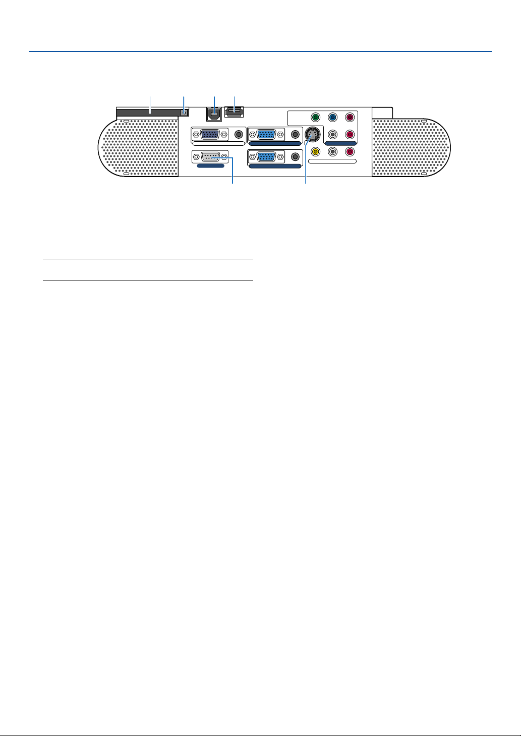
Te r minal Panel Features
COMPONENT
Y Cb/Pb Cr/Pr
AUDIO
AUDIO
AUDIO
AUDIO
L/MONO
S-VIDEO
COMPUTER 1AUDIO
PC CARD
USB(COMPUTER)
USB(MOUSE)
MONITOR OUT
COMPUTER 2
PC CONTROL
R
L/MONOVIDEO R
78
10
69
11
6. S-VIDEO Input Connector (Mini DIN 4 Pin)
Here is where you connect the S-Video input from an
external source like a VCR.
NOTE: S-Video provides more vivid color and higher
resolution than the traditional composite video format.
7. USB (MOUSE) Port (Type A)
Connect a commercially available USB mouse. You
can operate the menu or Viewer with the USB mouse
via this port.
8. USB (COMPUTER) Port (Type B)
Connect this port to the USB port (type A) of your PC
using the supplied USB cable. You can operate your
computer's mouse functions from the remote control.
9. PC CONTROL Port (D-Sub 9 Pin)
Use this port to connect your PC to control your pro-
jector via a serial cable. This enables you to use your
PC and serial communication protocol to control the
projector. A commercially available RS232C cross
cable is required to use this port. You can also control
the projector by using Dynamic Image Utility 2.0 in-
cluded on the supplied CD-ROM.
To do so you must first have Dynamic Image Utility
2.0 installed on your PC. If you are writing your own
program, typical PC control codes are on page 119.
10. PC CARD Slot
Insert a PC card here.
11. PC CARD Eject Button
Press to partially eject a PC card partially.
17
1. Introduction
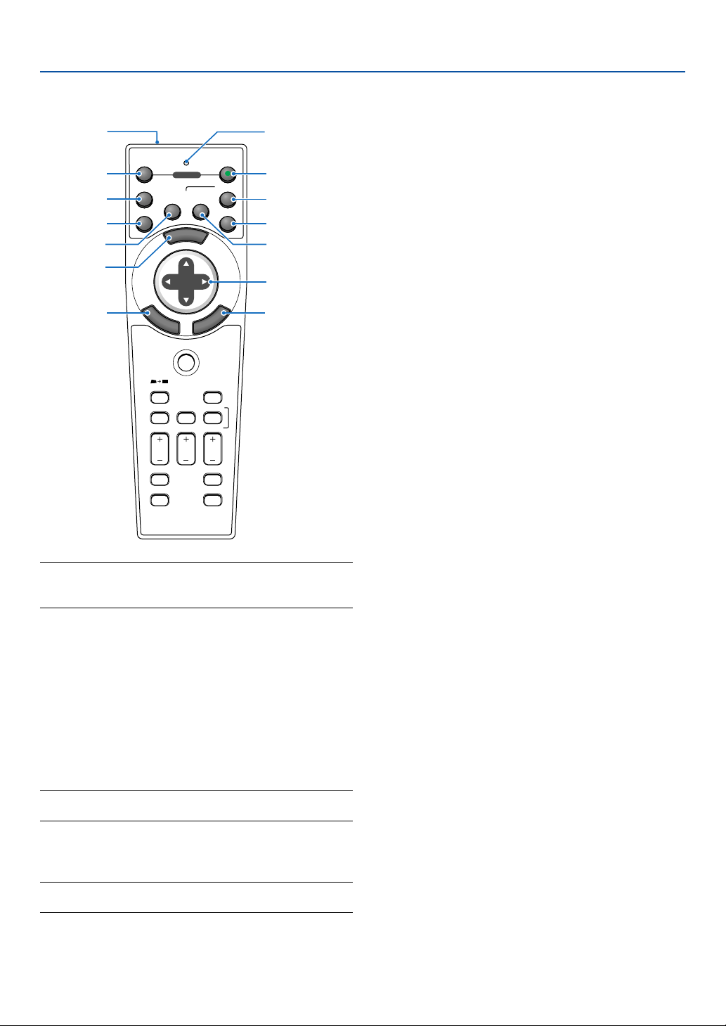
Part Names of the Remote Control
NOTE: If you are using a Macintosh computer, you can click
either the CANCEL (right-click) or ENTER (left-click) button to
activate the mouse.
1. Infrared Transmitter
Direct the remote control toward the remote sensor
on the projector cabinet.
2. LED
Flashes when any button is pressed.
3. POWER ON Button
When the main power is on, you can use this button
to turn your projector on.
NOTE: To turn on the projector, press and hold the POWER ON
button for a minimum of two seconds.
4. POWER OFF Button
You can use this button to turn your projector off.
NOTE: To turn off the projector, press and hold the POWER
OFF button for a minimum of two seconds.
SOURCE
FREEZE
VIEWER
3D REFORM
ASPECT
HELP
PICTURE
PIC-MUTE
POINTER
VOLUME MAGNIFY
SLIDE
PJ
OFF
12
VIDEO
S-VIDEO
AUTO ADJ.
COMPUTER
COMPONENT
ON
SELECT
POWER
M
E
N
U
E
N
T
E
R
C
A
N
C
E
L
1
2
4
5
6
7
11
13
3
10
8
9
14
12
5. VIDEO Button
Press this button to select a video source from a VCR,
DVD player, laser disc player or document camera.
6. S-VIDEO Button
Press this button to select an S-Video source from a
VCR.
7. COMPUTER 1 Button
Press this button to select COMPUTER 1 input.
8. COMPUTER 2 Button
Press this button to select COMPUTER 2 input.
9. AUTO ADJ. Button
Use this button to adjust an RGB source for an opti-
mal picture. See page 37.
10. COMPONENT Button
Press this button to select a video source from com-
ponent equipment connected to your COMPONENT
input.
11. MENU Button
Displays the menu for various settings and adjust-
ments.
12. SELECT 왖왔왗왘 (Mouse) Button
When you are in the Computer mode, these buttons
work as a computer mouse.
When you are in the Projector mode, which is indi-
cated by lighting the PJ button. See page 40.
왖왔 : Use these buttons to select the menu of the
item you wish to adjust.
왗왘 : Use these buttons to change the level of a se-
lected menu item. A press of the 왘 button ex-
ecutes the selection. When no menus appear,
these buttons work as a volume control.
When an image is magnified, the SELECT 왖왔왗왘
button moves the image.
13. ENTER (Left Click) Button
When you are in the Computer mode, this button works
as the mouse left button. When this button is pressed
and held for a minimum of 2 seconds, the drag mode
is set. When you are in the Projector mode, which is
indicated by lighting the PJ button: Use this button to
enter your menu selection. It works the same way as
the ENTER button on the cabinet. See page 40.
14. CANCEL (Right Click) Button
When you are in the Computer mode, this button works
as the mouse right button. When you are in the Pro-
jector mode, which is indicated by lighting the PJ but-
ton: It works the same way as the CANCEL button on
the cabinet. See page 40.
18
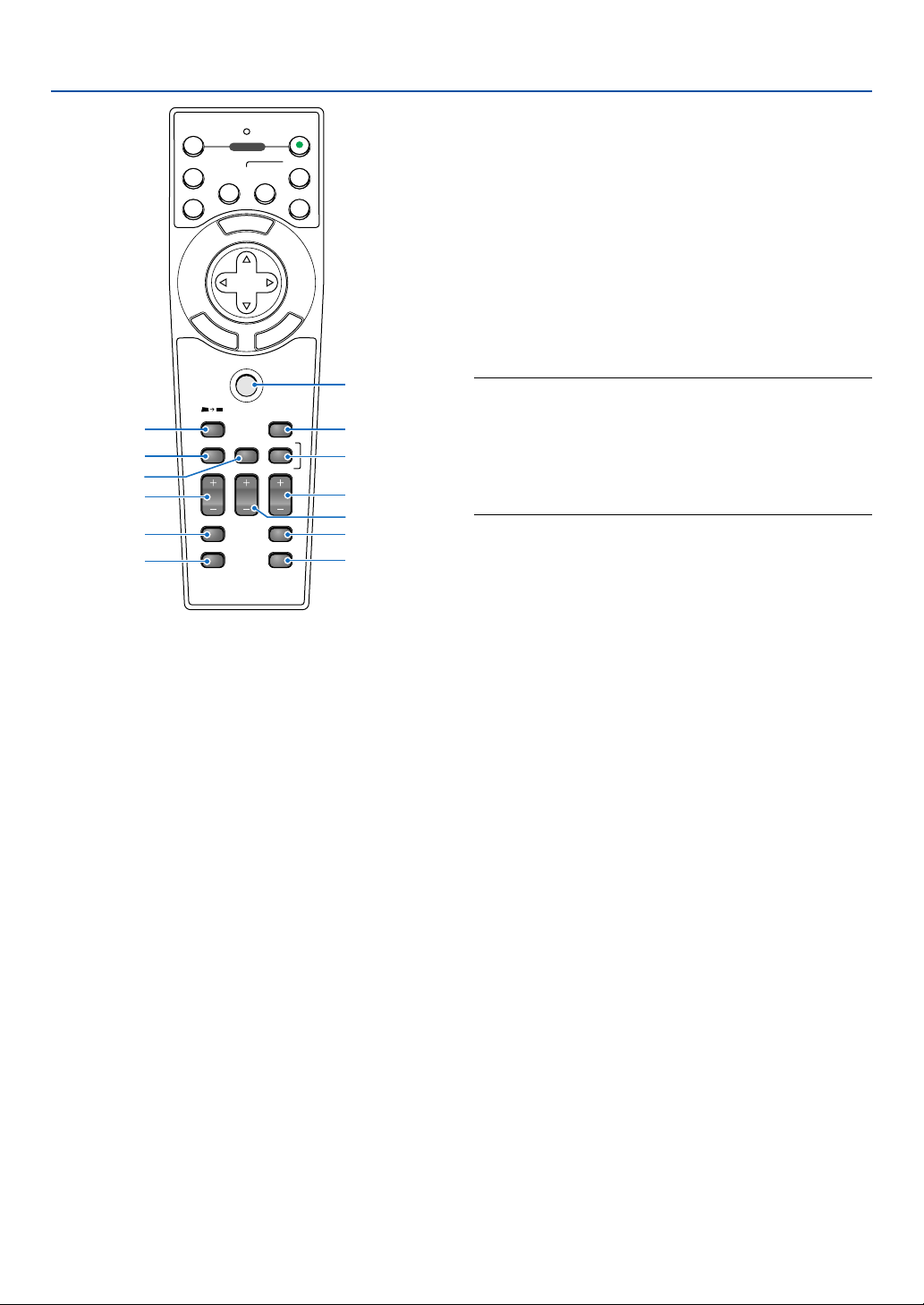
15. PJ Button
Press this button to switch the SELECT, CANCEL, and
ENTER buttons between the Projector mode (lit red)
and the Computer mode.
Press this button or any one of the POWER ON/OFF,
MENU, 3D REFORM, ASPECT, POINTER, HELP,
MAGNIFY, VIEWER or PICTURE buttons to switch to
the Projector mode and the PJ button lights red. To
switch back to the Computer mode, press the PJ but-
ton again. See page 40.
16. 3D REFORM Button
Press this button to enter 3D Reform to correct the
keystone (trapezoidal) distortion, and make the im-
age square. See pages 35 and 44.
17. SOURCE Button
Use this button to select a video source such as a PC,
VCR, DVD player or Viewer (PC card).
Press and release this button quickly to display the
Source List.
Each time this button is pressed for a minimum of ONE
second, the input source will change as follows:
Computer1 → Computer2 → Component → Video →
S-Video → Viewer → Entry List → Computer1 → ...
If no input signal is present, the input will be skipped.
M
E
N
U
E
N
T
E
R
C
A
N
C
E
L
OFF
12
VIDEO
S-VIDEO
AUTO ADJ.
COMPUTER
COMPONENT
ON
SELECT
POWER
PJ
SOURCE
FREEZE
VIEWER
3D REFORM
ASPECT
HELP
PICTURE
PIC-MUTE
POINTER
VOLUME MAGNIFY
SLIDE
16
18
17
24
25
21
26
27
15
19
20
22
23
18. ASPECT Button
Press this button to display the Aspect Ratio select
screen. See page 82.
19. POINTER Button
Press this button to display one of the nine pointers;
press again to hide the pointer. You can move your
pointer icon to the area you want on the screen using
the SELECT 왖왔왗왘 button. See page 41.
20. VOLUME (+)(–) Button
Press (+) to increase the volume and (–) to decrease
it.
NOTE: The default is the Computer mode, which allows you to
use the SELECT, CANCEL, and ENTER buttons as your computer
mouse. When the POWER ON/OFF, MENU, 3D REFORM, AS-
PECT, POINTER, HELP, MAGNIFY, VIEWER or PICTURE button
is pressed, the PJ button lights red to indicate that you are in the
Projector mode. If no buttons are pressed within 60 seconds,
the light goes out and the Projector mode is canceled.
21. MAGNIFY (+)(–) Button
Use this button to adjust the image size up to 400%.
The image is magnified about the center of the screen.
See page 41.
22. PICTURE Button
Press this button to display the Picture window. Each
time this button is pressed, the option will be changed.
See page 78.
23. PIC-MUTE Button
This button turns off the image and sound for a short
period of time.
Press again to restore the image and sound.
24. VIEWER Button
Press this button to select the Viewer source.
25. SLIDE (+)(–) Button
Press (+) to select the next folder or slide and (–) to
select the previous folder or slide. See page 58.
26. FREEZE Button
This button will freeze a picture. Press again to re-
sume motion.
27. HELP Button
Provides suitable HELP information.
1. Introduction
19
1. Introduction
30°
30°
30°
30°
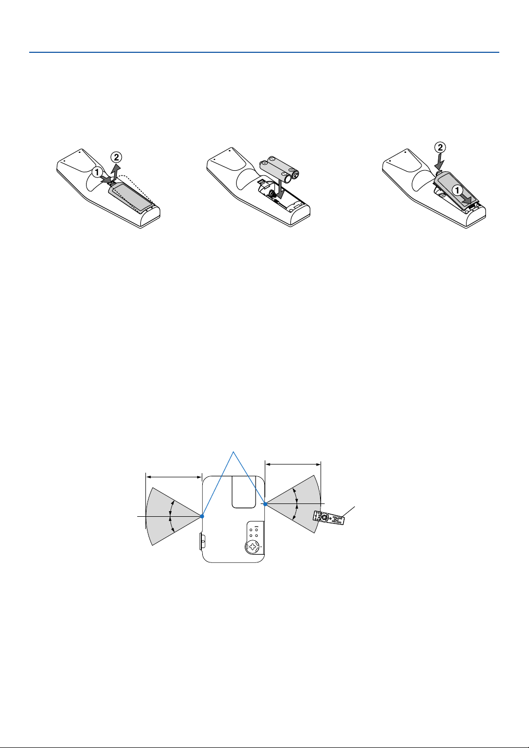
Note on Remote Control Operation
If you press and hold the SELECT 왖왔왗왘 button while installing new batteries, the remote control may fail to work
properly.
Should this happen, remove the batteries and then install them again without touching the SELECT button.
Remote Control Precautions
• Handle the remote control carefully.
• If the remote control gets wet, wipe it dry immediately.
•Avoid excessive heat and humidity.
• If you will not be using the remote control for a long time, remove the batteries.
• Do not place the batteries upside down.
• Do not use new and old batteries together, or use different types of batteries together.
Operating Range for Wireless Remote Control
Battery Installation
1
Remove the battery cover.
2
Remove both old batteries and in-
stall new ones (AA). Ensure that
you have the batteries' polarity (+/
-) aligned correctly.
3
Slip the cover back over the bat-
teries until it snaps into place. Do
not mix different types of batter-
ies or new and old batteries.
Remote sensor on projector cabinet
Remote control
7m/22 feet
7m/22 feet
• The infrared signal operates by line-of-sight up to a distance of about 22 feet/7 m and within a 60-degree angle of
the remote sensor on the projector cabinet.
• The projector will not respond if there are objects between the remote control and the sensor, or if strong light falls
on the sensor.
Weak batteries will also prevent the remote control from properly operating the projector.

20
2
Installation and Connections
○○○○○○○○○○○○○○○○○○○○○○○○○○○○○○○○○○○○○○○○
Setting Up the Screen and the Projector ................... 21
Selecting a Location ............................................................................................. 21
Throw Distance and Screen Size ......................................................................... 22
Making Connections .................................................. 23
Enabling the computer’s external display ............................................................. 23
Connecting Your PC or Macintosh Computer ....................................................... 23
To connect SCART output (RGB) ......................................................................... 24
Connecting an External Monitor ........................................................................... 25
Connecting Your DVD Player with Component Output ......................................... 26
Connecting Your VCR or Laser Disc Player .......................................................... 27
Connecting the Supplied Power Cable ................................................................. 28
21
This section describes how to set up your projector and how to connect PCs, video and audio sources.
2. Installation and Connections
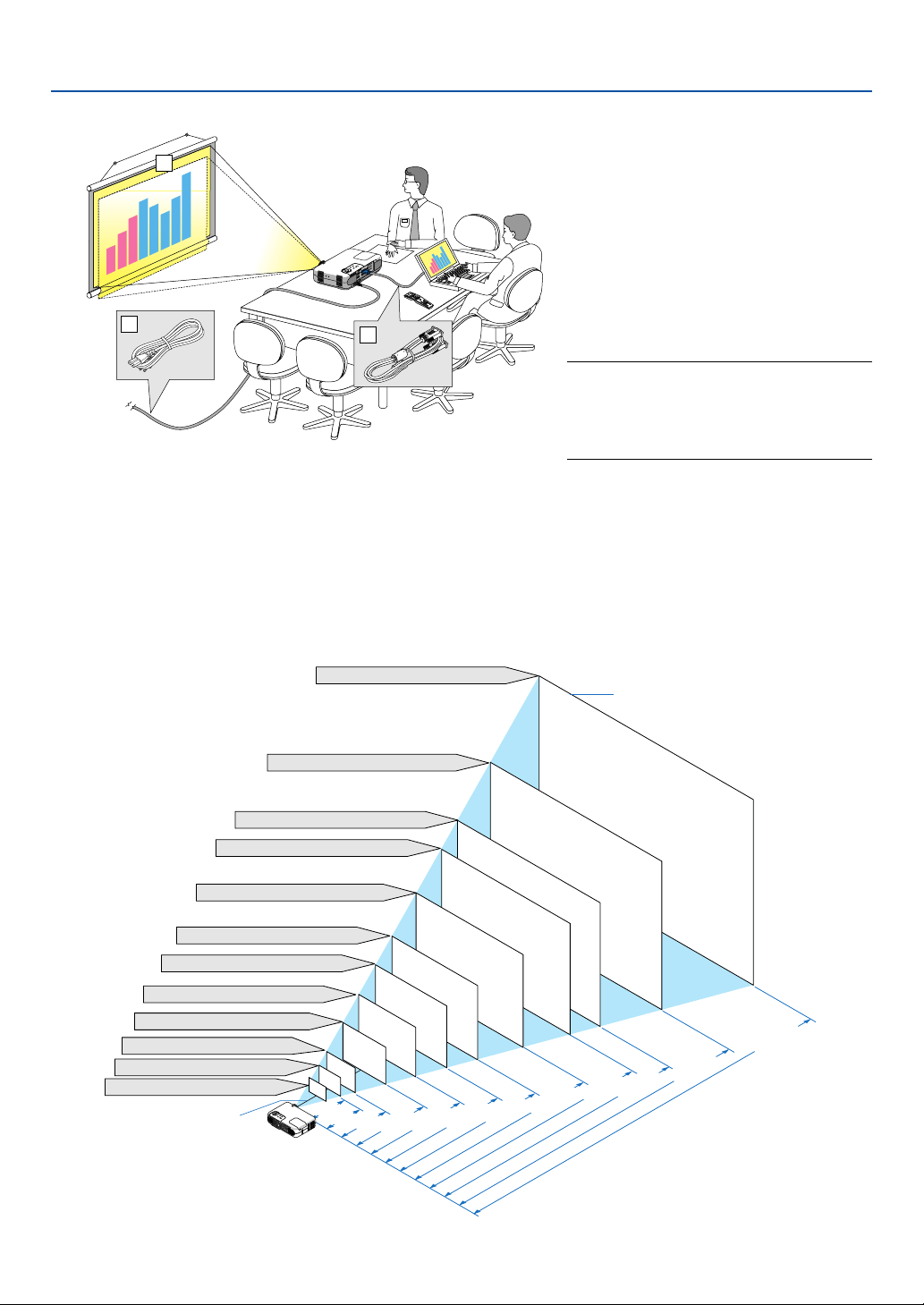
Setting Up the Screen and the Projector
Selecting a Location
The further your projector is from the screen or wall, the larger the image. The minimum size the image can be is
approximately 25" (0.64 m) measured diagonally when the projector is roughly 31.5 inches (0.8 m) from the wall or
screen. The largest the image can be is 300" (7.6 m) when the projector is about 393.7 inches (10 m) from the wall or
screen. Use the drawing below as a guide.
Your projector is simple to set up and use.
But before you get started, you must first:
z Set up a screen and the projector.
x Connect your computer or video equip-
ment to the projector. See pages 23 -
27.
c Connect the supplied power cable. See
page 28.
NOTE: Ensure that the power cable and any
other cables are disconnected before moving
the projector. When moving the projector or
when it is not in use, cover the lens with the
lens cap.
To the wall outlet.
0.8
31.5
300"
240"
200"
180"
150"
120"
100"
60"
40
"
30
"
25
"
80"
Distance (Unit: m/inch)
Screen size (Unit: cm/inch)
Screen size
Lens center
609.6 (W) 457.2 (H) / 240 (W) 180 (H)
487.7 (W) 365.8 (H) / 192 (W) 144 (H)
406.4 (W) 304.8 (H) / 160 (W) 120 (H)
365.8 (W) 274.3 (H) / 144 (W) 108 (H)
304.8 (W) 228.6 (H) / 120 (W) 90 (H)
243.8 (W) 182.9 (H) / 96 (W) 72 (H)
203.2 (W) 152.4 (H) / 80 (W) 60 (H)
162.6 (W) 122.0 (H) / 64 (W) 48 (H)
121.9 (W) 91.4 (H) / 48 (W) 36 (H)
81.3 (W) 61.0 (H) / 32 (W) 24 (H)
61.0 (W) 45.7 (H) / 24 (W) 15 (H)
50.8 (W) 38.1 (H) / 20 (W) 15 (H)
1.0
39.4
1.3
51.2
2.0/78.7
2.6/102.4
3.3/129.9
4.0/157.5
5.0/196.9
6.0/236.2
6.7/263.8
8.0/315.0
10.0/393.7
3
2
1
3
D
R
E
F
O
R
M
S
O
U
R
C
E
S
E
L
E
C
T
S
T
A
T
U
S
L
A
M
P
P
C
C
A
R
D
P
O
W
E
R
O
N
/
S
T
A
N
D
B
Y
A
U
T
O
A
D
J
U
S
T
M
E
N
U
E
N
T
E
R
C
A
N
C
E
L
Z
O
O
M
F
O
C
U
S
A
C
I
N
22
2. Installation and Connections
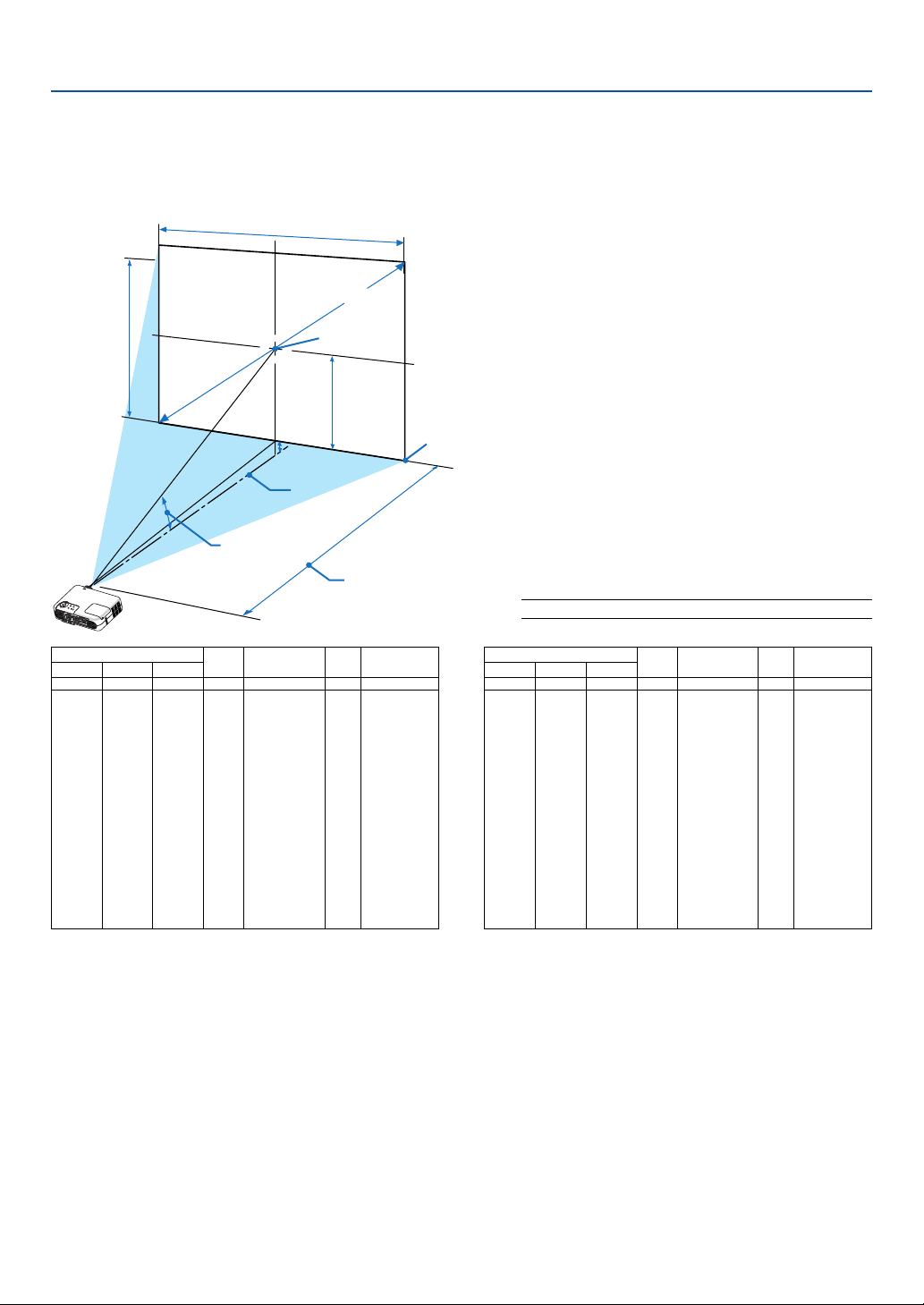
Lens Center
Throw Angle (움)
Throw Distance (C)
Screen center
Screen Diagonal
Screen Width
Screen Height
Screen Bottom
(B)
(D)
WARNING
* Installing your projector on the ceiling must be done
by a qualified technician. Contact your NEC dealer for
more information.
* Do not attempt to install the projector yourself.
• Only use your projector on a solid, level surface. If the
projector falls to the ground, you can be injured and
the projector severely damaged.
• Do not use the projector where temperatures vary
greatly. The projector must be used at temperatures
between 32°F (0°C) and 95°F (35°C).
• Do not expose the projector to moisture, dust, or
smoke. This will harm the screen image.
Throw Distance and Screen Size
The following shows the proper relative positions of the projector and screen. Refer to the table to determine the
position of installation.
Distance Chart
B =Vertical distance between lens center and
screen center
C = Throw distance
D =Vertical distance between lens center and
bottom of screen (top of screen for ceiling
application)
α = Throw angle
NOTE: Distances may vary +/-5%.
α
Wide – Tele
degree
12.1 - 9.9
12.0 - 9.9
11.8 - 9.7
11.7 - 9.6
11.6 - 9.6
11.6 - 9.6
11.6 - 9.6
11.6 - 9.6
11.6 - 9.6
11.5 - 9.6
11.5 - 9.5
11.5 - 9.5
11.5 - 9.5
11.4 - 9.5
11.4 - 9.5
11.4 - 9.5
11.4 - 9.5
11.4 - 9.5
11.4 - 9.5
inch
15.0
18.0
24.0
36.0
40.0
43.0
48.0
50.0
54.0
60.0
72.0
90.0
108.0
120.0
132.0
144.0
156.0
168.0
180.0
Screen Size B C
Wide – Tele
D
Diagonal Width Height
inch
28.0 - 34.0
34.0 - 41.0
46.0 - 56.0
70.0 - 85.0
78.0 - 95.0
84.0 - 102.0
94.0 - 114.0
98.0 - 120.0
106.0 - 128.0
118.0 - 143.0
141.0 - 172.0
177.0 - 215.0
213.0 - 258.0
237.0 - 287.0
261.0 - 316.0
285.0 - 345.0
309.0 - 374.0
333.0 - 403.0
356.0 - 431.0
inch
-2.0
-2.0
-2.0
-4.0
-4.0
-4.0
-5.0
-5.0
-5.0
-6.0
-7.0
-9.0
-11.0
-12.0
-13.0
-14.0
-16.0
-17.0
-18.0
inch
6.0
7.0
10.0
14.0
16.0
17.0
19.0
20.0
22.0
24.0
29.0
36.0
43.0
48.0
53.0
58.0
62.0
67.0
72.0
inch
25
30
40
60
67
72
80
84
90
100
120
150
180
200
220
240
260
280
300
inch
20.0
24.0
32.0
48.0
54.0
58.0
64.0
67.0
72.0
80.0
96.0
120.0
144.0
160.0
176.0
192.0
208.0
224.0
240.0
α
Wide – Tele
degree
12.1 - 9.9
12.0 - 9.9
11.8 - 9.7
11.7 - 9.6
11.6 - 9.6
11.6 - 9.6
11.6 - 9.6
11.6 - 9.6
11.6 - 9.6
11.5 - 9.6
11.5 - 9.5
11.5 - 9.5
11.5 - 9.5
11.4 - 9.5
11.4 - 9.5
11.4 - 9.5
11.4 - 9.5
11.4 - 9.5
11.4 - 9.5
mm
381
457
610
914
1021
1097
1219
1280
1372
1524
1829
2286
2743
3048
3353
3658
3962
4267
4572
Screen Size B C
Wide – Tele
D
Diagonal Width Height
mm
710 - 870
860 - 1050
1170 - 1420
1770 - 2160
1990 - 2410
2140 - 2600
2380 - 2890
2500 - 3040
2680 - 3260
2990 - 3620
3590 - 4360
4500 - 5460
5410 - 6560
6020 - 7290
6630 - 8030
7230 - 8760
7840 - 9490
8450 - 10230
9050 - 10960
mm
-38
-46
-61
-91
-102
-110
-122
-128
-137
-152
-183
-229
-274
-305
-335
-366
-396
-427
-457
mm
152
183
244
366
408
439
488
512
549
610
732
914
1097
1219
1341
1463
1585
1707
1829
mm
635
762
1016
1524
1702
1829
2032
2134
2286
2540
3048
3810
4572
5080
5588
6096
6604
7112
7620
mm
508
610
813
1219
1361
1463
1626
1707
1829
2032
2438
3048
3658
4064
4470
4877
5283
5690
6096
• Ensure that you have adequate ventilation around your
projector so heat can dissipate. Do not cover the vents
on the side of the projector.
Reflecting the Image
Using a mirror to reflect your projector's image enables
you to enjoy a much larger image. Contact your NEC
dealer if you need a mirror. If you're using a mirror and
your image is inverted, use the MENU and SELECT
buttons on your projector cabinet or your remote control
to correct the orientation. See page 86.
23
2. Installation and Connections
Making Connections
NOTE: When using with a notebook PC, be sure to connect between the projector and the notebook PC before turning on the
power to the notebook PC. In most cases signal cannot be output from RGB output unless the notebook PC is turned on after
connecting with the projector.
* If the screen goes blank while using your remote control, it may be the result of the computer's screen-saver or power
management software.
* If you accidentally hit the POWER button on the remote control, wait 60 seconds and then press the POWER button again to
resume.
AC IN
COMPONENT
Y Cb/Pb Cr/Pr
AUDIO
AUDIO
L/MONO
S-VIDEO
AUDIO
PC CARD
USB(COMPUTER)
USB(MOUSE)
MONITOR OUT
PC CONTROL
R
L/MONOVIDEO R
AUDIO
AUDIO
COMPUTER 1
COMPUTER 2
COMPUTER 1
COMPUTER 2
AUDIO
AUDIO
PHONE
PHONE
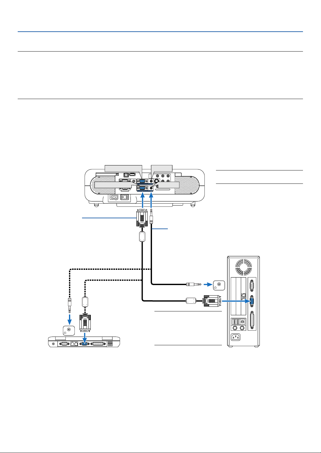
Connecting Your PC or Macintosh Computer
RGB signal cable (supplied)
To mini D-Sub 15-pin connector on the
projector. It is recommended that you
use a commercially available distribu-
tion amplifier if connecting a signal
cable longer than the supplied one.
Audio cable (not supplied)
IBM PC or Compatibles (Desktop type)
or Macintosh (Desktop type)
NOTE: For older Macintosh,
use a commercially available
pin adapter (not supplied) to
connect to your Mac's video
port.
IBM VGA or Compatibles (Notebook
type) or Macintosh (Notebook type)
Connecting your PC or Macintosh computer to your projector will enable you to project your computer's screen image
for an impressive presentation.
To connect to a PC or Macintosh, simply:
1. Turn off the power to your projector and computer.
2. Use the supplied signal cable to connect your PC or Macintosh to the projector.
3. Connect the supplied power cable. See page 28.
4. Turn on the projector and the computer.
5. If the projector goes blank after a period of inactivity, it may be caused by a screen saver installed on the computer
you've connected to the projector.
NOTE: The COMPUTER 1 connector
supports Plug & Play (DDC2).
Enabling the computer’s external display
Displaying an image on the notebook PC’s screen does not necessarily mean it outputs a signal to the projector.
When using a PC compatible laptop, a combination of function keys will enable/disable the external display.
Usually, the combination of the ‘Fn” key along with one of the 12 function keys gets the external display to come on
or off. For example, NEC laptops use Fn + F3, while Dell laptops use Fn + F8 key combinations to toggle through
external display selections.
24
NOTE: The VT770 is not compatible with video decoded outputs of NEC ISS-6020 and ISS-6010 switchers.
NOTE: An image may not be displayed correctly when a Video or S-Video source is played back via a commercially available scan
converter.
This is because the projector will process a video signal as a computer signal at the default setting. In that case, do the following.
* When an image is displayed with the lower and upper black portion of the screen or a dark image is not displayed correctly:
Project an image to fill the screen and then press the AUTO ADJ button on the remote control or the AUTO ADJUST button on
the projector cabinet.
* When noise appears on the sides of the screen:
Use the Overscan feature to display the image correctly.
Be sure to change the Overscan to 0% before pressing the AUTO ADJ or AUTO ADJUST button, otherwise an image may be
displayed with its sides cut off.
2. Installation and Connections
AC IN
COMPONENT
YCb/Pb Cr/Pr
AUDIO
AUDIO
L/MONO
S-VIDEO
AUDIO
PC CARD
USB(COMPUTER)
USB(MOUSE)
MONITOR OUT
PC CONTROL
R
L/MONOVIDEO R
AUDIO
AUDIO
COMPUTER 1
COMPUTER 2
COMPUTER 2
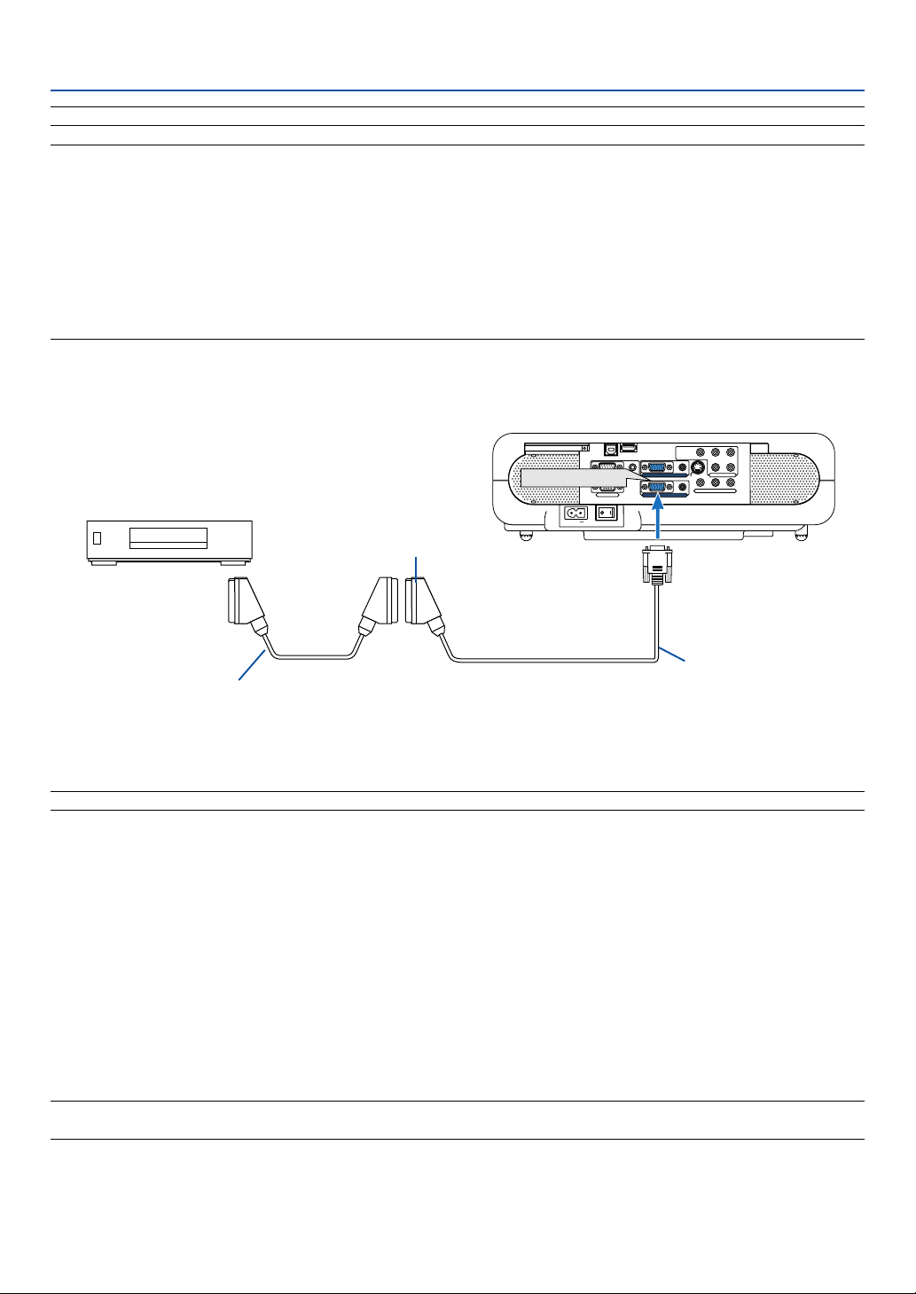
Before connections: An exclusive SCART adapter (ADP-SC1) and a commercially available SCART cable are re-
quired for this connection.
NOTE: Audio signal is not available for this connection.
1. Turn off the power to the projector and your video equipment.
2. Use the NEC ADP-SC1 SCART adapter and a commercially available SCART cable to connect the RGB input of
your projector and a SCART output (RGB) of your video equipment.
3. Connect the supplied power cable. See page 28.
4. Turn on the power to the projector and your video equipment.
5. Use the COMPUTER 2 button on the remote control to select the COMPUTER 2 input.
6. Press the MENU button on the remote control to display the menu.
7. From the menu, select [Setup] → [Page3] → [Signal Select] → [Computer 2] → [Scart].
SCART is a standard European audio-visual connector for TVs, VCRs and DVD players. It is also referred to as
Euro-connector.
NOTE: The ADP-SC1 SCART adapter is obtainable from your NEC dealer in Europe. Contact your NEC dealer in Europe for more
information.
To connect SCART output (RGB)
Video equipment such as DVD player
Commercially available SCART cable
Female
ADP-SC1
To COMPUTER 2 input
Projector
25
2. Installation and Connections
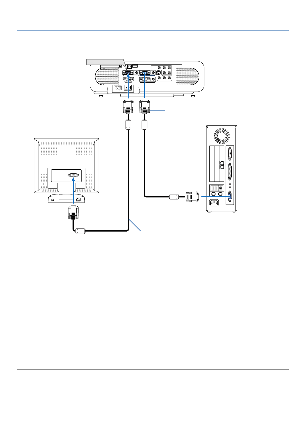
Connecting an External Monitor
AC IN
COMPONENT
Y Cb/Pb Cr/Pr
AUDIO
AUDIO
AUDIO
L/MONO
S-VIDEO
PC CARD
USB(COMPUTER)
USB(MOUSE)
COMPUTER 2
PC CONTROL
R
L/MONOVIDEO R
AUDIOMONITOR OUT AUDIOCOMPUTER 1
MONITOR OUT
You can connect a separate, external monitor to your projector to simultaneously view on a monitor the RGB analog
image you're projecting.
To do so:
1. Turn off the power to your projector, monitor and computer.
2. Use a 15-pin cable to connect your monitor to the MONITOR OUT (Mini D-Sub 15 pin) connector on your projector.
3. Connect the supplied power cable. See page 28.
4. Turn on the projector, monitor and the computer.
NOTE:
• The MONITOR OUT connector outputs RGB signal during Idle mode. When the projector goes into standby mode, the image on
an external monitor disappears for a moment.
• When the projector is in the standby mode, the image may not be correctly displayed while the cooling fans are running
immediately after turning on or off the power.
• Daisy chain connection is not possible.
RGB signal cable (supplied)
RGB signal cable (not supplied)
26
AUDIO IN
LR
AUDIO OUT
L R
Component
YCbCr
AC IN
AUDIO
AUDIO
S-VIDEO
COMPUTER 1AUDIO
PC CARD
USB(COMPUTER)
USB(MOUSE)
MONITOR OUT
COMPUTER 2
PC CONTROL
L/MONOVIDEO R
COMPONENT
YCb/Pb Cr/Pr
AUDIO
AUDIO
L/MONO R
COMPONENT
AUDIO
2. Installation and Connections
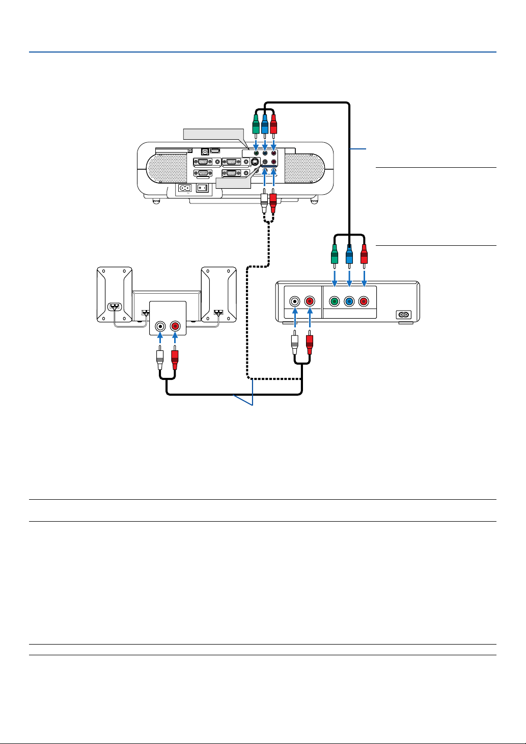
You can connect your projector to a DVD player with component output or Video output. To do so, simply:
NOTE: For a DVD player without component video (Y,Cb,Cr/Y, Pb, Pr) output, use an S-Video cable (not provided) to connect an
S-Video output of the DVD player to the S-VIDEO input of the projector.
1. Turn off the power to your projector and DVD player.
2. If your DVD player has the component video (Y,Cb,Cr/Y, Pb, Pr) output, use a commercially available component
video cable (RCA3) to connect your DVD player to the COMPONENT input connectors on the projector.
Use an audio cable (not supplied) to connect the audio from your DVD player to your audio equipment (if your DVD
player has this capability). Be careful to keep your right and left channel connections correct for stereo sound.
3. Connect the supplied power cable. See page 28.
4. Turn on the projector and DVD player.
NOTE: Refer to your DVD player's owner's manual for more information about your DVD player's video output requirements.
Connecting Your DVD Player with Component Output
Component video RCA
3
cable (not supplied)
DVD player
Audio Equipment
Audio cable (not supplied)
NOTE: The "Y" connector accepts
a Video signal. A Video signal
will be automatically displayed. If
not, from the menu, select
[Setup]
→
[Page 3]
→
[Signal
Select]
→
[Component]
→
[Video].
27
2. Installation and Connections
AC IN
COMPONENT
YCb/Pb Cr/Pr
AUDIO
AUDIO
AUDIO
AUDIO
L/MONO
S-VIDEO
COMPUTER 1AUDIO
PC CARD
USB(COMPUTER)
USB(MOUSE)
MONITOR OUT
COMPUTER 2
PC CONTROL
R
L/MONOVIDEO R
AUDIO IN
LR
AUDIO OUT
L R
VIDEO OUT
S-VIDEO VIDEO
S-VIDEO
VIDEO
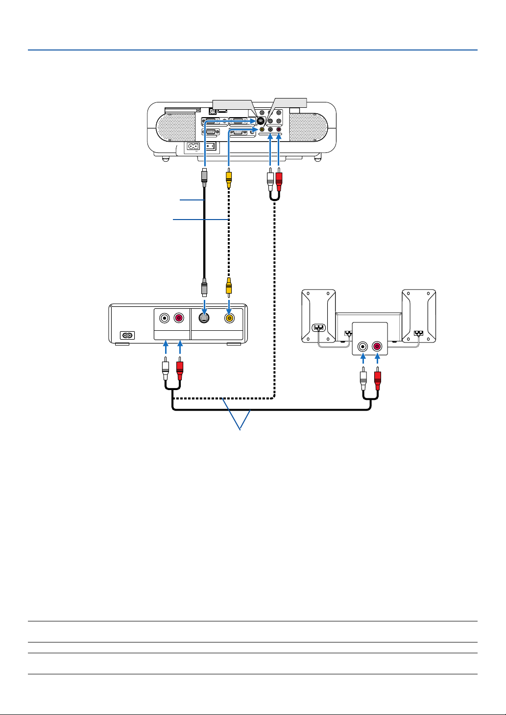
Connecting Your VCR or Laser Disc Player
S-Video cable (not supplied)
Video cable (not supplied)
VCR/ Laser disc player
Audio equipment
Audio cable (not supplied)
Use an RCA or S-Video cable (not provided) to connect the video and use RCA cables (not provided) to connect
the audio from your VCR, laser disc player or document camera to your projector.
To make these connections, simply:
1. Turn off the power to the projector and VCR, laser disc player or document camera.
2. Connect one end of an RCA cable to the video output (or one end of an S-Video cable to the S-Video output
connector) on the back of your VCR or laser disc player, connect the other end to the appropriate video input
on your projector. Connect one end of a pair RCA cables (not supplied) to the audio output on the back of your
VCR or laser disc player, connect the other end to your audio equipment or to the appropriate audio input on
the projector.
Be careful to keep the right and left channel connections correct for stereo sound.
3. Connect the supplied power cable. See page 28.
4. Turn on the projector and the VCR or laser disc player.
NOTE: Refer to your VCR or laser disc player owner's manual for more information about your equipment's video output
requirements.
NOTE: An image may not be displayed correctly when a Video or S-Video source is played back in fast-forward or fast-rewind via
a scan converter.
28
2. Installation and Connections
A
C
IN
COMPONENT
Y
Cb/Pb Cr/Pr
AUDIO
AUDIO
AUDIO
S-VIDEO
COMPUTER 1
AUDIO
PC CARD
U
S
B
(C
O
M
PU
TER)
US
B(M
O
U
SE)
MONITOR OUT
COMPUTER 2
PC CONTROL
L/MONO
VIDEO
R
COMPONENT
Y Cb/Pb
Cr/Pr
AUDIO
AUDIO
L/MONO R
PC CARD
3D REFORM
SOURCE
STATUS
LAMP
POWER
O
N
/ST
AN
D
B
Y
A
U
T
O
A
D
JU
S
T
S
E
L
E
C
T
M
E
N
U
E
N
T
E
R
C
A
N
C
E
L
Z
O
O
M
F
O
C
U
S
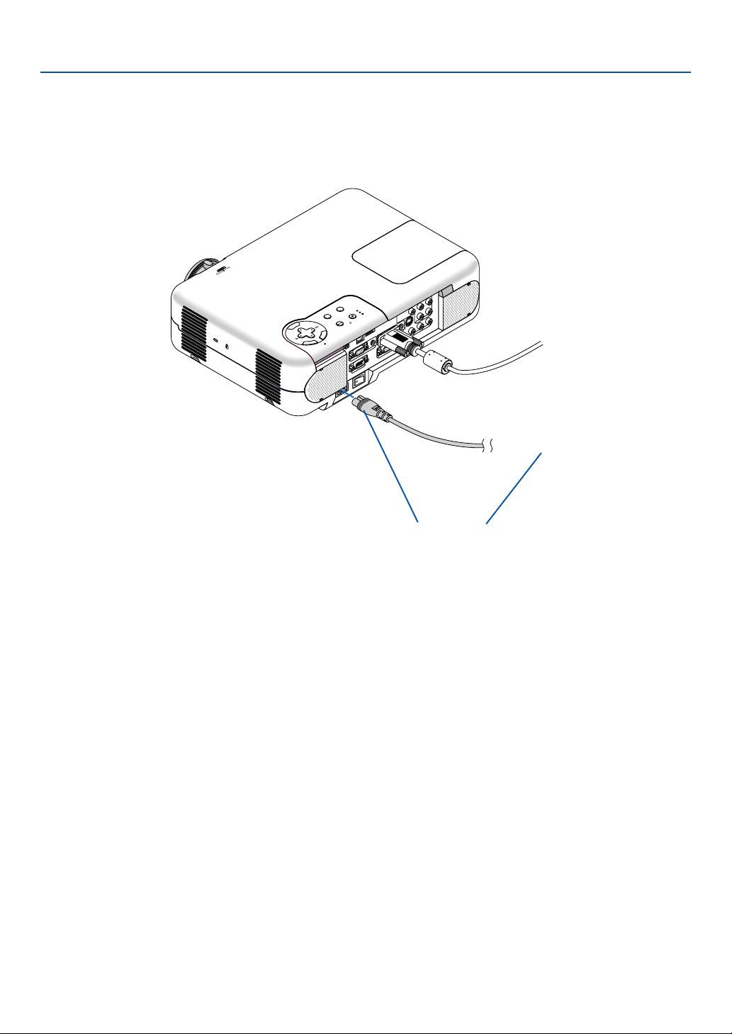
Connecting the Supplied Power Cable
Connect the supplied power cable to the projector.
First connect the supplied power cable's two-pin plug to the AC IN of the projector, and then connect the other plug of
the supplied power cable in the wall outlet.
Make sure that the prongs are fully
inserted into both the AC IN and the
wall outlet.
→
To wall outlet
29
3
Projecting an Image
(Basic Operation)
○○○○○○○○○○○○○○○○○○○○○○○○○○○○○○○○○○○○○○○○
Tur ning on the Projector............................................. 30
Selecting a Source .................................................... 32
Adjusting the Picture Size and Position ..................... 33
Correcting Keystone Distortion .................................. 35
Optimizing RGB Picture Automatically ...................... 37
Tur ning Up or Down Volume ...................................... 37
Tur ning off the Projector............................................. 38
After Use.................................................................... 38
30
3. Projecting an Image (Basic Operation)
This section describes how to turn on the projector and to project a picture onto the screen.
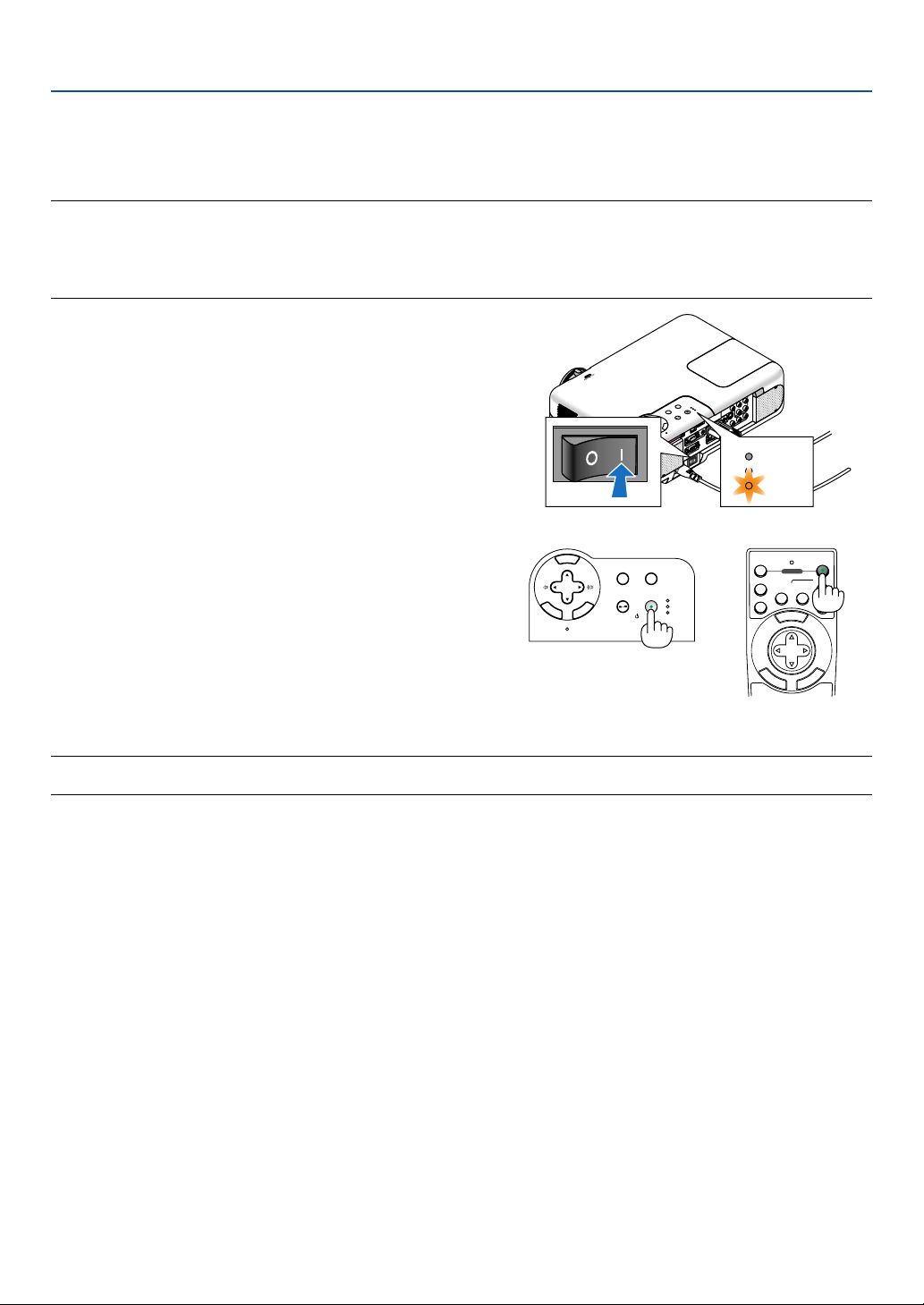
Turning on the Projector
NOTE:
• The projector has two power switches: a main power switch and a POWER (ON/STAND BY) button (POWER ON and OFF on the
remote control).
• When plugging in or unplugging the supplied power cable, make sure that the main power switch is pushed to the off (
)
position. Failure to do so may cause damage to the projector.
C
r
/
P
r
STATUS
LAMP
POWER
To turn on the main power to the projector, press
the Main Power switch to the on position ( I ).
After you turn on your projector, ensure that the
computer or video source is turned on and that your
lens cap is removed.
Only after you press the POWER (ON/STAND BY)
button on the projector cabinet or POWER ON but-
ton on the remote control for a minimum of 2 sec-
onds will the power indicator turn to green and the
projector become ready to use.
3D REFORM
SOURCE
SELECT
STATUS
LAMP
PC CARD
POWER
ON/STAND BY
AUTO ADJUST
M
E
N
U
E
N
T
E
R
C
A
N
C
E
L
M
E
N
U
E
N
T
E
R
C
A
N
C
E
L
OFF
12
VIDEO
S-VIDEO
AUTO ADJ.
COMPUTER
COMPONENT
ON
SELECT
POWER
NOTE: When no signal is available, a blue, black or logo screen is displayed.
When the projector displays a blue or a black screen (not logo), the Eco mode will be automatically selected in "Lamp Mode."
31
3. Projecting an Image (Basic Operation)
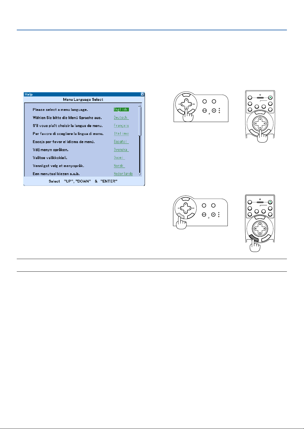
Note on Startup screen (Menu Language Select screen)
When you first turn on the projector, you will get the Startup screen. This screen gives you the opportunity to select one
of the 19 menu languages.
To select a menu language, follow these steps:
1. Use the SELECT
왖
or
왔
button to select one of the
19 languages for the menu.
3D REFORM
SOURCE
STATUS
LAMP
PC CARD
POWER
ON/STAND BY
AUTO ADJUST
M
E
N
U
E
N
T
E
R
C
A
N
C
E
L
SELECT
M
E
N
U
E
N
T
E
R
C
A
N
C
E
L
OFF
12
VIDEO
S-VIDEO
AUTO ADJ.
COMPUTER
COMPONENT
ON
SELECT
POWER
2. Press the ENTER button to execute the
selection.
After this has been done, you can proceed to the menu
operation.
If you want, you can select the menu language later.
See "Language" on page 86.
3D REFORM
SOURCE
SELECT
STATUS
LAMP
PC CARD
POWER
ON/STAND BY
AUTO ADJUST
M
E
N
U
E
N
T
E
R
C
A
N
C
E
L
M
E
N
U
OFF
12
VIDEO
S-VIDEO
AUTO ADJ.
COMPUTER
COMPONENT
ON
SELECT
POWER
E
N
T
E
R
C
A
N
C
E
L
NOTE: Immediately after turning on the projector, screen flicker may occur. This is not a fault. Wait 3 to 5 minutes until the lamp
lighting is stabilized.
When the Lamp mode is set to Eco, the Lamp indicator will light green.
If one of the following things happens, the projector will not turn on.
• If the internal temperature of the projector is too high, the projector detects abnormal high temperature. In this
condition the projector will not turn on to protect the internal system. If this happens, wait for the projector's internal
components to cool down.
• When the lamp reaches its end of usable life, the projector will not turn on. If this happens, replace the lamp. See
page 107.
• If the lamp fails to light, and if the STATUS indicator flashes on and off in a cycle of six times, wait a full minute and
then turn on the power.
32
3. Projecting an Image (Basic Operation)
Selecting a Source
Selecting the computer or video source
3D REFORM
SOURCE
SELECT
STATUS
LAMP
PC CARD
POWER
ON/STAND BY
AUTO ADJUST
M
E
N
U
E
N
T
E
R
C
A
N
C
E
L
M
E
N
U
E
N
T
E
R
C
A
N
C
E
L
PJ
OFF
AUTO ADJ.
ON
SELECT
POWER
12
VIDEO
S-VIDEO
COMPUTER
COMPONENT
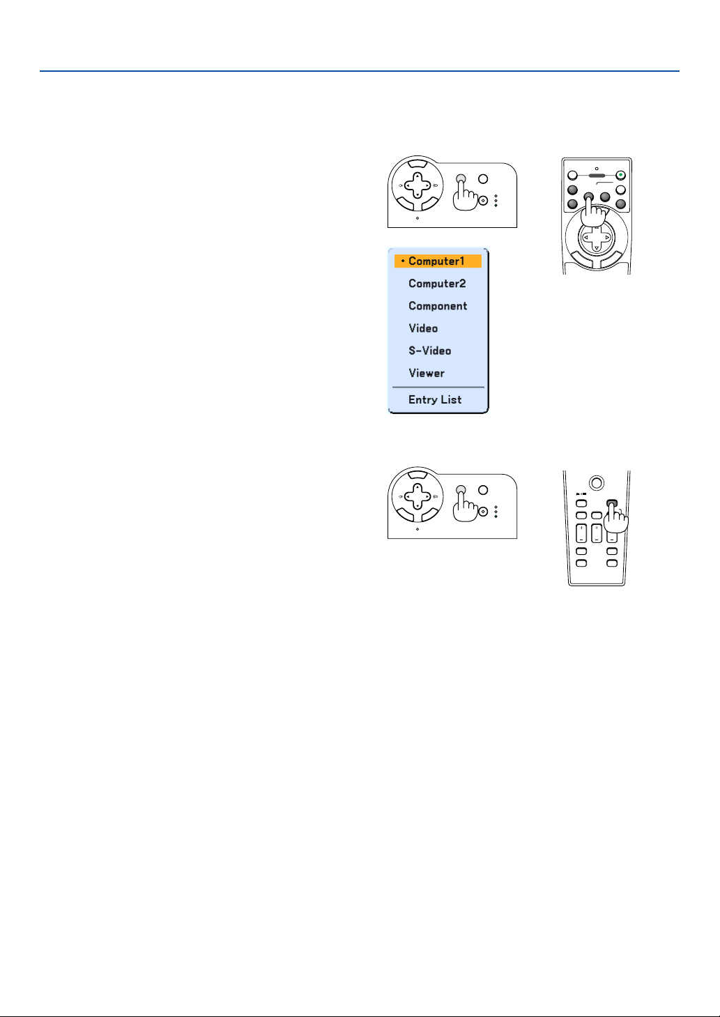
Using the Remote Control
Press any one of the COMPUTER 1/2, COMPONENT, VIDEO,
S-VIDEO or VIEWER buttons.
Selecting from Source List
Press and quickly release the SOURCE button on the projec-
tor cabinet to display the Source list. Each time the SOURCE
button is pressed, the input source will change as follows:
"Computer 1/2", "Component" (DVD player), "Video" (VCR or
laser disc player), “S-Video" or "Viewer" (slides on a PC card).
To display the selected source, press the ENTER button.
Detecting the Signal Automatically
Press and hold the SOURCE button for a minimum of 1 sec-
ond, the projector will search for the next available input
source. Each time you press and hold the SOURCE button
for a minimum of 1 second, the input source will change as
follows:
Computer1 → Computer2 → Component → Video → S-Video
→ Viewer → Computer1 → ...
If no input signal is present, the input will be skipped. When
the input source you wish to project is displayed, release the
button.
3D REFORM
SOURCE
SELECT
STATUS
LAMP
PC CARD
POWER
ON/STAND BY
AUTO ADJUST
M
E
N
U
E
N
T
E
R
C
A
N
C
E
L
PJ
SOURCE
FREEZE
VIEWER
3D REFORM
ASPECT
HELP
PICTURE
PIC-MUTE
POINTER
VOLUME MAGNIFY
SLIDE
VIEWER
33
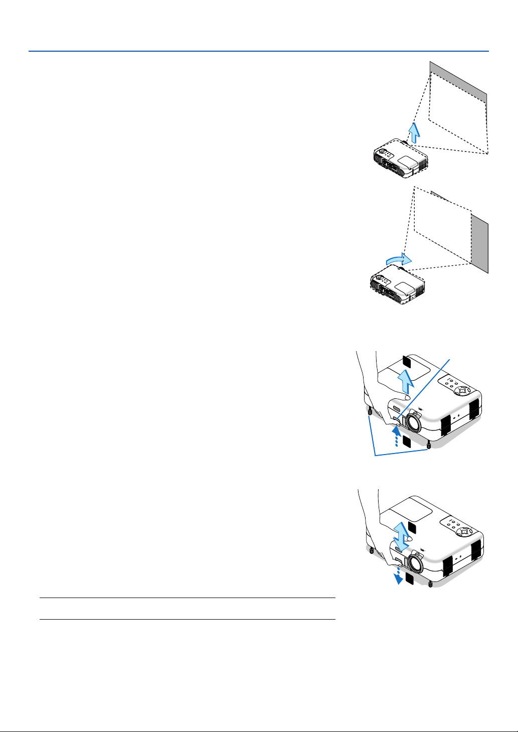
3. Projecting an Image (Basic Operation)
Place your projector on a flat level surface and ensure that the projector is
square to the screen.
Lift the front edge of the projector to center the image vertically.
If the projected image does not appear square to the screen then use the
Keystone feature for proper adjustment. See pages 35 and 44.
Adjusting the Picture Size and Position
Adjust the Tilt Foot
1. Lift the front edge of the projector.
2. Push up and hold the Adjustable Tilt Foot Button on the front of the
projector to extend the adjustable tilt feet (maximum height: 30mm/
1.2”).
3. Lower the front of the projector to the desired height.
4. Release the Adjustable Tilt Foot Button to lock the Adjustable tilt
foot.
There is approximately 10 degrees of up and down adjustment for
the front of the projector.
Adjusting the height of a projected image or changing projection
angle will run the Auto Keystone correction function to quickly
correct the vertical distortion. The "Keystone" screen will be dis-
played.
For operating the "Keystone" screen, see "
Correcting Vertical
Keystone Distortion" on page 35.
NOTE: Your "Keystone" correction data can be reset by pressing and holding the 3D
REFORM button for a minimum of 2 seconds.
CAUTION
Do not use the tilt-foot for purposes other than originally intended.
Misuses such as gripping the tilt-foot or hanging on the wall can cause dam-
age to the projector.
Adjustable Tilt
Foot Button
3D
R
E
FO
R
M
S
O
U
R
CE
S
E
L
E
C
T
S
TA
TU
S
LAM
P
P
C
C
A
RD
P
O
W
E
R
O
N
/
S
T
A
N
D
B
Y
A
U
T
O
A
D
J
U
S
T
M
E
N
U
E
N
T
E
R
C
A
N
C
E
L
Z
O
O
M
F
O
C
U
S
1
2
3D REFORM
SOURCE
SELECT
STATUS
LAMP
PC CARD
POWER
ON
/STAND BY
AUTO AD
JU
ST
M
E
N
U
E
N
T
E
R
C
A
N
C
E
L
Z
O
O
M
FOCUS
4
3
Adjustable Tilt Foot
Rotate the projector's front right or left (to the right in this example) to center
the image horizontally on the screen.
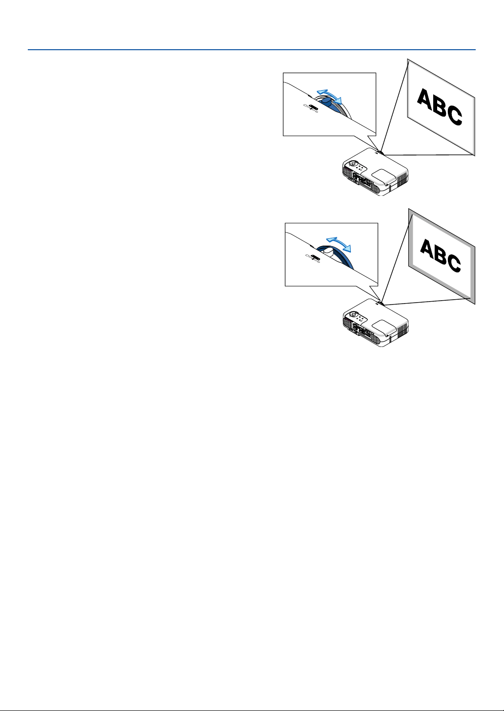
34
3. Projecting an Image (Basic Operation)
ZOOM
F
O
C
U
S
Z
O
O
M
FO
CU
S
Zoom
Use the ZOOM lever to finely adjust the image size on the screen.
You can use the ZOOM lever to enlarge or reduce an image size.
Focus
Use the FOCUS ring to obtain the best focus.
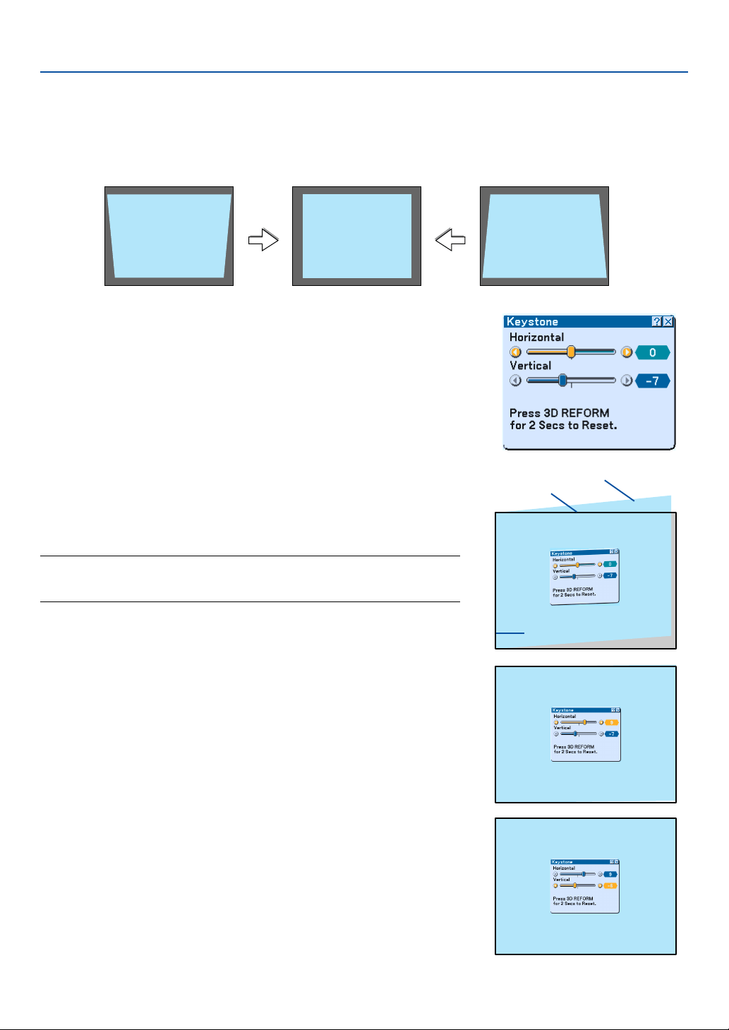
35
Correcting Keystone Distortion
Auto Keystone Correction
The Auto Keystone correction feature will correct vertical distortion of a projected image on the screen. No special
operation required. Just put the projector on a flat surface.
Manual Keystone Correction
You can also correct keystone distortion manually.
To do so:
1. Extend the Adjustable Tilt Foot to adjust the height of a projected
image. See page 33.
The Keystone screen will be displayed on the screen.
• If the Keystone screen disappears, press the MENU button or
ENTER button once to display the Keystone screen again.
2. Align the left (or right) side of the screen with the left (or right)
side of the projected image.
• Use the shorter side of the projected image as the base.
• In the right example, use the left side as the base.
NOTE: When "Manual" is selected in "Keystone" from the menu, project an image
adjusting projector position so that the screen is smaller than the area of the
projected image. See page 87 for selecting "Manual" in "Keystone".
3. Use the SELECT
왗
or
왘
button to select “Horizontal”.
Perform the keystone correction.
3. Projecting an Image (Basic Operation)
Screen frame
Projected area
Align left side
4. If the right and left sides of the projected image are not parallel to
each other, use the SELECT
왔
button to select “Vertical” and use
the SELECT
왗왘
button.
Fine adjust so that both sides are parallel to each other.

36
5. Repeat steps 3 and 4 to correct keystone distortion.
6. After completing Keystone correction, press the ENTER button.
The Keystone screen will disappear.
• To perform Keystone correction again, press the 3D REFORM button
to display the Keystone screen and repeat above steps 1 to 6.
NOTE:
•Turning on the projector will reset the previous correction setting values if the projection angle is changed from the last use.
If the projection angle is the same as in the last use, the previous correction setting values are retained in the memory.
To use the previous correction setting values after changing projection angle, select "Manual" in "Keystone" from the menu. See
page 87.
To return the 3D Reform correction setting values to the factory preset, press and hold the 3D REFORM button for a minimum
of 2 seconds.
• Each time the 3D REFORM button is pressed, the item will change as follows: Keystone
→
Cornerstone
→
None
→
Keystone
→
...
For information on “Cornerstone”, see “Correcting Horizontal and Vertical Keystone Distortion (Cornerstone) on page 44.
3. Projecting an Image (Basic Operation)
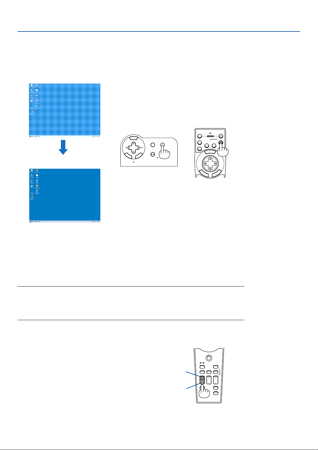
37
3. Projecting an Image (Basic Operation)
Optimizing RGB Picture Automatically
Adjusting the Image Using Auto Adjust
Optimizing an RGB image automatically.
Press the Auto Adjust button to optimize an RGB image automatically.
[Poor picture]
[Normal picture]
3D REFORM
SOURCE
SELECT
STATUS
LAMP
PC CARD
POWER
ON/STAND BY
AUTO ADJUST
M
E
N
U
E
N
T
E
R
C
A
N
C
E
L
M
E
N
U
E
N
T
E
R
C
A
N
C
E
L
OFF
12
VIDEO
S-VIDEO
AUTO ADJ.
COMPUTER
COMPONENT
ON
SELECT
POWER
Press the Auto Adjust button to fine-tune the computer image or to remove any vertical band-
ing that might appear and to reduce video noise, dot interference or cross talk (this is evident
when part of your image appears to be shimmering). This function adjusts the clock frequen-
cies that eliminate the horizontal banding in the image. This function also adjusts the clock
phase to reduce video noise, dot interference or cross talk. (This is evident when part of your
image appears to be shimmering.)
This adjustment may be necessary when you connect your computer for the first time.
NOTE:
• Some signals may not be displayed correctly or take time.
• The Auto Adjust function does not work for component and video signals.
• If the Auto Adjust operation cannot optimize the RGB signal, try to adjust Clock and Phase manually.
See page 84.
Turning Up or Down Volume
Increase volume
Decrease volume
PJ
SOURCE
FREEZE
VIEWER
3D REFORM
ASPECT
HELP
PICTURE
PIC-MUTE
POINTER
VOLUME MAGNIFY
SLIDE
Sound level from the speaker and the AUDIO OUT
jack (Stereo mini) on the projector can be adjusted.
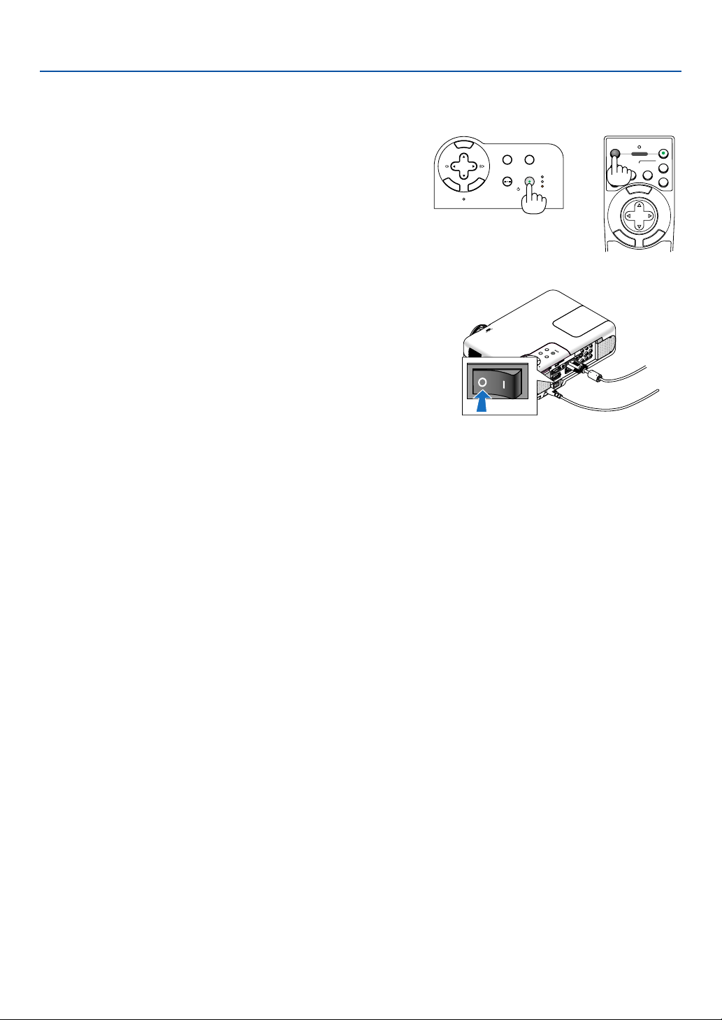
38
Turning off the Projector
To turn off the projector:
3. Projecting an Image (Basic Operation)
3D REFORM
SOURCE
SELECT
STATUS
LAMP
PC CARD
POWER
ON/STAND BY
AUTO ADJUST
M
E
N
U
E
N
T
E
R
C
A
N
C
E
L
M
E
N
U
E
N
T
E
R
C
A
N
C
E
L
OFF
12
VIDEO
S-VIDEO
AUTO ADJ.
COMPUTER
COMPONENT
ON
SELECT
POWER
First, press the POWER (ON/STAND BY) button on the projec-
tor cabinet or the POWER OFF button on the remote control for
a minimum of two seconds.
The power indicator will glow orange. After the projector turns
off, the cooling fans keep operating for 10 seconds (Cooling-off
time).
Secondly, turn off the Main Power switch. The power indicator
will go out.
Finally unplug the power cable.
CAUTION
Do not unplug the power cable from the wall outlet or do not turn off
the main power under any one of the following circumstances.
Doing so can cause damage to the projector:
• While the Hour Glass icon appears.
• While the cooling fans are running. (The cooling fans continue to
work for 10 seconds after the projector is turned off).
Cr/Pr
After Use
Preparation: Make sure that the projector is not turned on.
1. Unplug the power cable.
2. Disconnect any other cables.
3. Retract adjustable tilt feet if extended.
4. Cover the lens with the lens cap.
5. Put the projector and its accessories in the supplied soft carrying case.

39
4
Convenient Features
○○○○○○○○○○○○○○○○○○○○○○○○○○○○○○○○○○○○○○○○
Switching Operation Mode between
Computer and Projector ........................................ 40
Tur ning Off the Image and Sound .............................. 40
Freezing a Picture...................................................... 40
Using the Pointer ....................................................... 41
Enlarging and Moving a Picture................................. 41
Getting the On-line Help ............................................ 42
Using a USB Mouse .................................................. 42
Using the Remote Mouse Function ........................... 43
Correcting Horizontal and Vertical Keystone
Distortion (Cornerstone) ........................................ 44
쐅 Making Freehand Drawings
on a Projected Image (ChalkBoard) ...................... 47
쐈 Storing Images Displayed on the Projector
on the PC card or USB Memory (Capture) ............ 48
쐉 Preventing the Unauthorized Use of the Projector .... 49
씈 Using a USB Memory Device or
USB Memory Card Reader.................................... 54
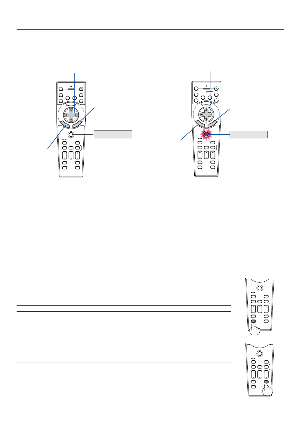
40
PJ
M
E
N
U
E
N
T
E
R
C
A
N
C
E
L
SOURCE
FREEZE
OFF
12
VIDEO
S-VIDEO
AUTO ADJ.
COMPUTER
VIEWER
COMPONENT
ON
3D REFORM
ASPECT
HELP
PICTURE
PIC-MUTE
POINTER
VOLUME MAGNIFY
SLIDE
SELECT
POWER
PJ
M
E
N
U
E
N
T
E
R
C
A
N
C
E
L
SOURCE
FREEZE
OFF
12
VIDEO
S-VIDEO
AUTO ADJ.
COMPUTER
VIEWER
COMPONENT
ON
3D REFORM
ASPECT
HELP
PICTURE
PIC-MUTE
POINTER
VOLUME MAGNIFY
SLIDE
SELECT
POWER
Not lit
Works as a mouse for your computer.
Works as a right-click button
for your computer.
Works as the SELECT button on the projector.
Lit red
Works as the CANCEL
button on the projector.
Works as a left-click
button for your com-
puter.
Works as the ENTER
button on the projector.
Switching Operation Mode between Computer and Projector
The three shaded buttons shown on the drawing work as a computer mouse in the Computer mode.
In the Computer mode the PJ button is not lit.
4. Convenient Features
• When the MENU button is pressed, the PJ button lights red to indicate that you are in the Projector mode,
which allows the projector menu operation using the three buttons.
• If no buttons are pressed within 60 seconds, the PJ button's light goes out to indicate that you are in the
Computer mode. To enable the projector menu operation again, press the PJ button to light red.
• When the PJ button is lit, if you want to use the mouse function immediately, press the PJ button to return to the
Computer mode (not lit).
During Computer mode
In Computer mode, by pressing the ENTER button for 2 seconds or more then releasing, the drag mode is set and the
drag operation can be performed simply by pressing the SELECT 왖왔왗왘 (mouse) button. To drop the item, press the
ENTER (left click) button again or press the CANCEL (right click) button.
Turning Off the Image and Sound
Press the PIC-MUTE button to turn off the image and sound for a short period of time. Press
again to restore the image and sound.
NOTE: When a picture is muted, the Eco mode will be automatically selected in "Lamp Mode."
PJ
SOURCE
FREEZE
VIEWER
3D REFORM
ASPECT
HELP
PICTURE
PIC-MUTE
POINTER
VOLUME MAGNIFY
SLIDE
Freezing a Picture
Press the FREEZE button to freeze a picture. Press again to resume motion.
NOTE: Pressing the FREEZE button will display the Capture menu that allows you to capture a freezed
image. See page 48 for more information.
PJ
SOURCE
FREEZE
VIEWER
3D REFORM
ASPECT
HELP
PICTURE
PIC-MUTE
POINTER
VOLUME MAGNIFY
SLIDE
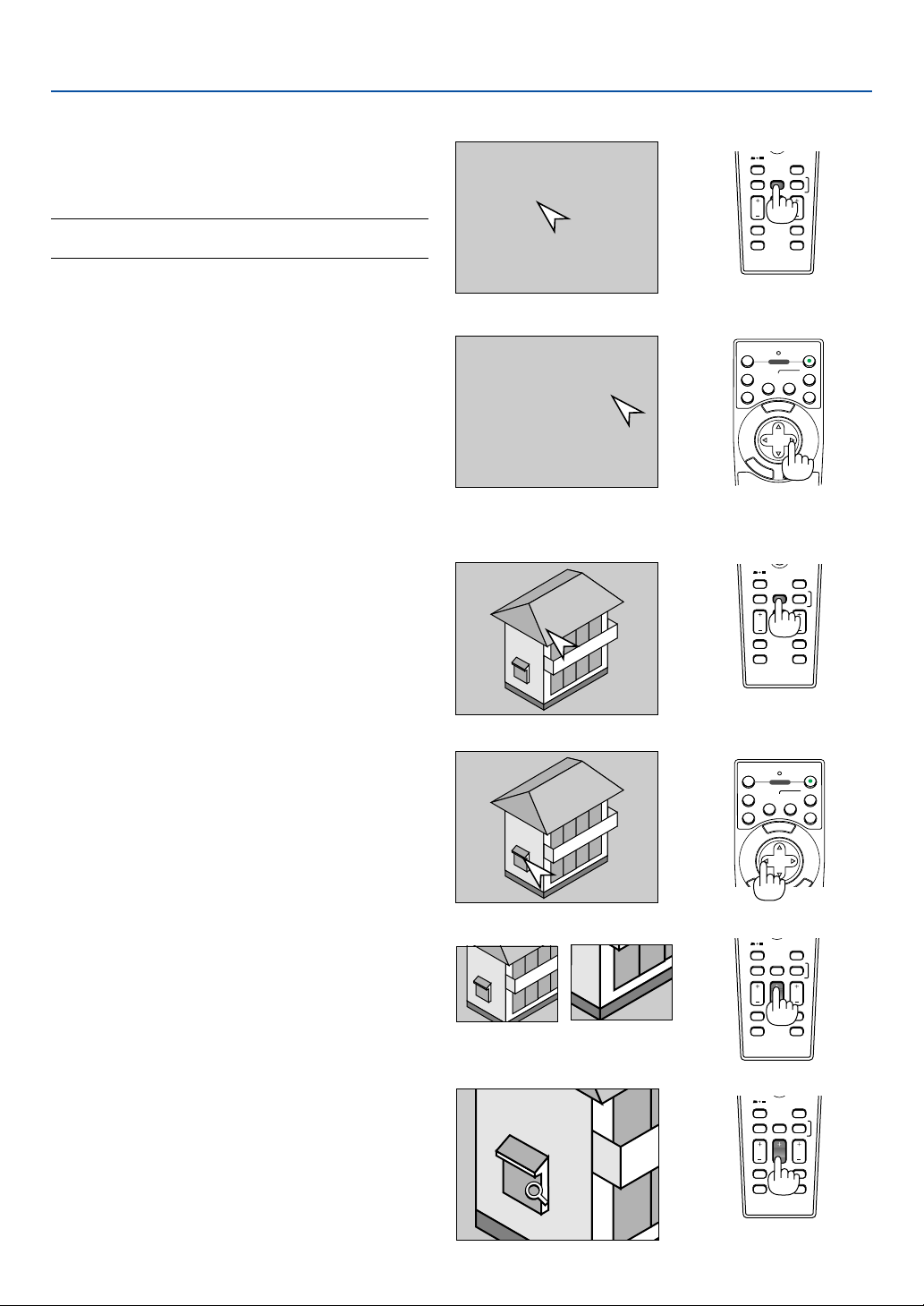
41
4. Convenient Features
Using the Pointer
Press the Pointer button to
display the pointer.
Use the Select button to move
the pointer.
SOURCE
FREEZE
VIEWER
3D REFORM
ASPECT
HELP
PICTURE
PIC-MUTE
POINTER
VOLUME MAGNIFY
SLIDE
You can use one of nine pointers to draw your
audience's attention to the portion of a projected im-
age you want.
NOTE: You can select one pointer from the menu. See page
99.
Press the POINTER button to display the pointer.
Use the SELECT button to move the pointer.
Press the POINTER buton again. The pointer will dis-
appear.
M
E
N
U
E
N
T
E
R
C
A
N
C
E
L
OFF
12
VIDEO
S-VIDEO
AUTO ADJ.
COMPUTER
COMPONENT
ON
SELECT
POWER
Enlarging and Moving a Pic-
ture
You can enlarge the area you want up to 400 percent.
To do so:
1. Press the POINTER button to display the
pointer.
SOURCE
FREEZE
VIEWER
3D REFORM
ASPECT
HELP
PICTURE
PIC-MUTE
POINTER
VOLUME MAGNIFY
SLIDE
M
E
N
U
E
E
L
OFF
12
VIDEO
S-VIDEO
AUTO ADJ.
COMPUTER
COMPONENT
ON
SELECT
POWER
2. Move the pointer to the area you want to
enlarge.
SOURCE
FREEZE
VIEWER
3D REFORM
ASPECT
HELP
PICTURE
PIC-MUTE
POINTER
VOLUME MAGNIFY
SLIDE
3. Enlarge the selected area.
When the MAGNIFY (+) button is pressed, the
image is magnified and the magnify icon will
be displayed. To magnify the selected area,
use the SELECT
왖왔왗왘
button to move the
magnify icon and press the MAGNIFY (+)
button.
4. Return the image to the original size.
Press the MAGNIFY (-) button until the
magnify icon changes to the pointer.
SOURCE
FREEZE
VIEWER
3D REFORM
ASPECT
HELP
PICTURE
PIC-MUTE
POINTER
VOLUME MAGNIFY
SLIDE
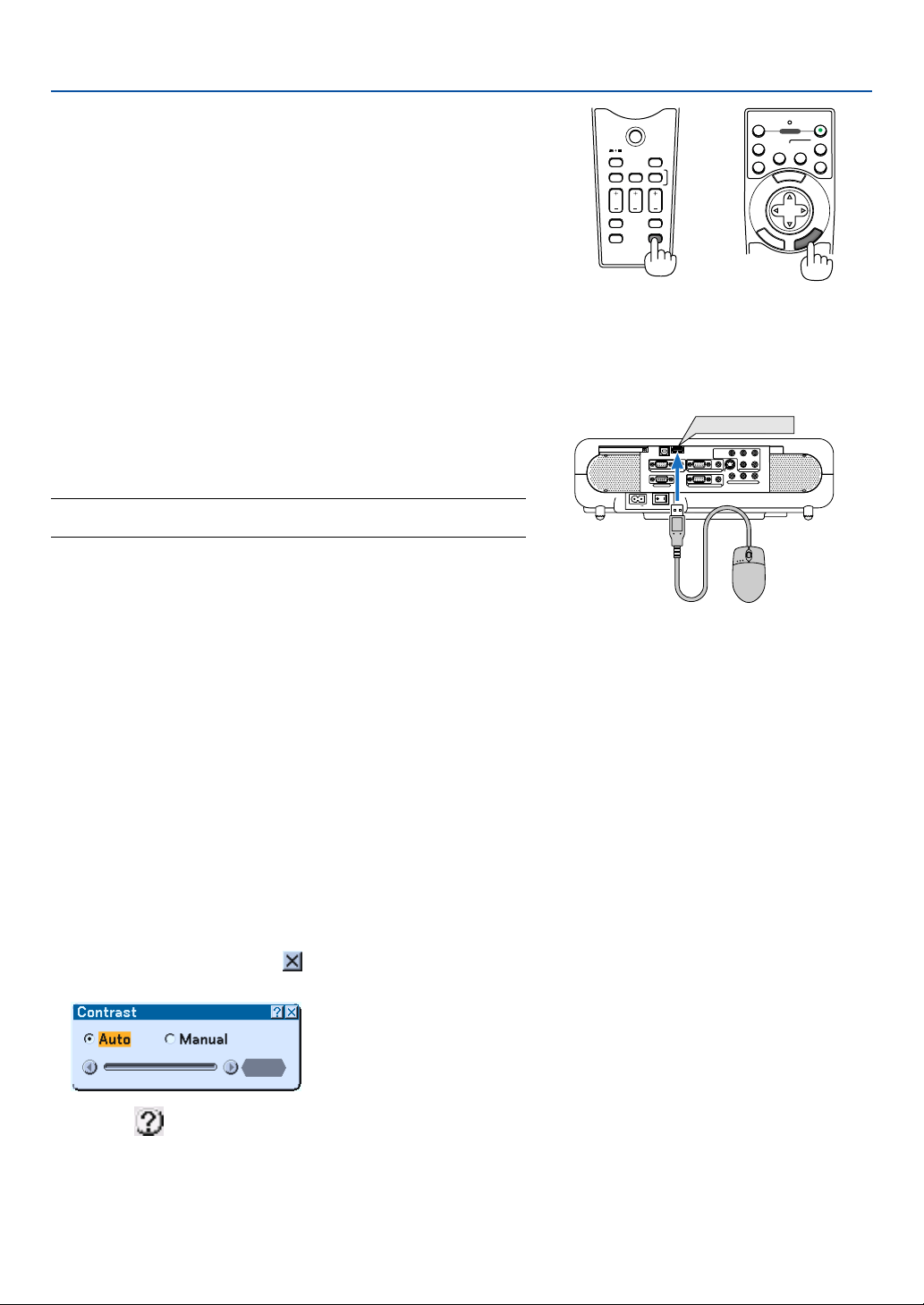
42
Getting the On-line Help
You get the contents about Help.
Display Help
Exit Help
4. Convenient Features
PJ
SOURCE
FREEZE
VIEWER
3D REFORM
ASPECT
HELP
PICTURE
PIC-MUTE
POINTER
VOLUME MAGNIFY
SLIDE
AC IN
COMPONENT
Y Cb/Pb Cr/Pr
AUDIO
AUDIO
AUDIO
AUDIO
L/MONO
S-VIDEO
COMPUTER 1AUDIO
PC CARD
USB(COMPUTER)
USB(MOUSE)
MONITOR OUT
COMPUTER 2
PC CONTROL
R
L/MONOVIDEO R
USB(MOUSE)
Using a USB Mouse
Using a USB mouse gives you a smooth operation. A commercially
available USB mouse can be used.
NOTE: There may be some brands of a USB mouse that the projector does
not support.
Operate the Menus using the USB mouse
Mouse Cursor
When connecting a USB mouse to the projector, you get a mouse cursor on the screen.
Unless you use your USB mouse within 10 seconds, the mouse cursor disappears.
Menu Display
Clicking with the right mouse button displays the menu.
To close the menu, click anywhere in the background.
Source List Display
Click with the left button anywhere on the screen except on the menu to display the Source list.
Adjusting and Setting Display
You can select a menu item and click with the left mouse button to make adjustments and settings.
Examples
Click (or press and hold) the left mouse button 왗 or 왘 to adjust the brightness. Or click and drag the left mouse
button on the slide bar horizontally to adjust it.
To save the adjustments, click
. The display is closed.
• Click with the left mouse button to display a description of the selected menu item.
• Click and drag the title bar with the left mouse button to move the adjustment or setting dialog box.
• Use the right mouse button (right-click) on the adjustment or setting dialog box to return to the previous
screen with storing changes.
M
E
N
U
OFF
12
VIDEO
S-VIDEO
AUTO ADJ.
COMPUTER
COMPONENT
ON
SELECT
POWER
E
N
T
E
R
C
A
N
C
E
L
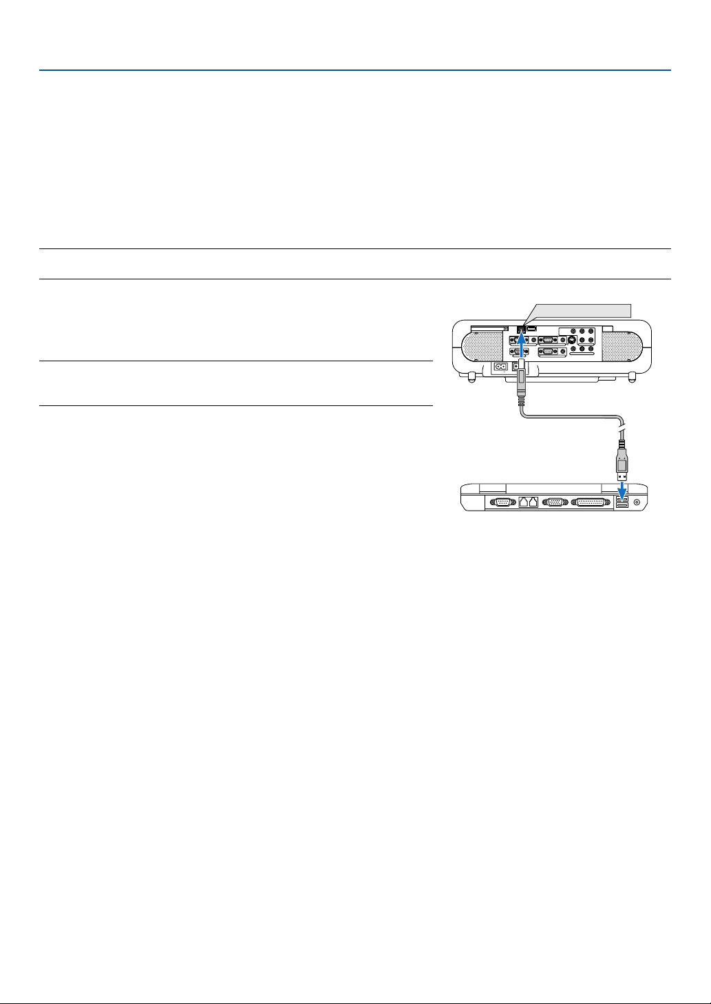
43
4. Convenient Features
Using the Remote Mouse Function
The built-in remote mouse function enables you to operate your computer's mouse functions from the remote control
(Computer mode).
It is very convenient for clicking through your computer-generated presentations. To return to the projector operation
mode (Projector mode), press the PJ button (lit red).
Connecting to your computer for the remote mouse function
If you wish to use the remote mouse function, use the supplied USB cable to connect the USB port (COMPUTER) of
the projector and the USB port (type A) of your computer.
NOTE: Depending on the type of connection or OS installed on your computer, you may have to restart your computer or change
your computer settings.
When using the USB Port
The remote mouse function can only be used with a Windows 98, Win-
dows Me, Windows XP, Windows 2000 or Mac OS operating system.
NOTE: Wait at least 5 seconds after disconnecting the USB cable before
reconnecting it and vice versa. The computer may not identify the built-in mouse
receiver if it is repeatedly connected and disconnected in rapid intervals.
AC IN
COMPONENT
Y Cb/Pb Cr/Pr
AUDIO
AUDIO
AUDIO
AUDIO
L/MONO
S-VIDEO
COMPUTER 1AUDIO
PC CARD
USB(COMPUTER)
USB(MOUSE)
MONITOR OUT
COMPUTER 2
PC CONTROL
R
L/MONOVIDEO R
USB(COMPUTER)
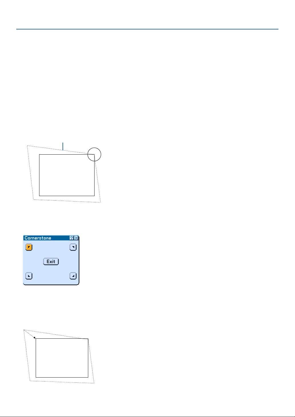
44
Correcting Horizontal and Vertical Keystone Distortion (Cor-
nerstone)
Use the 3D Reform feature to correct keystone (trapezoidal) distortion to make the top or bottom and the left or right
side of the screen longer or shorter so that the projected image is rectangular.
4. Convenient Features
Screen
Projected image
Cornerstone
1. Press and hold the 3D REFORM button for a minimum of 2 seconds to reset current adjustments.
Current adjusments for “Keystone” or “Cornerstone” will be cleared.
2. Project an image so that the screen is smaller than the area of the raster.
3. Pick up any one of the corners and align the corner of the screen with the one of the image.
The drawing shows the
upper right corner.
4. Press the 3D REFORM button on the remote control twice.
The Cornerstone adjustment screen is displayed.
Screen
5. Use the SELECT
왖왔왗왘
button to select one icon which points in the direction you wish to move the
projected image frame.
6. Press the ENTER button.
7. Use the SELECT
왖왔왗왘
button to move the projected image frame as shown on the example.
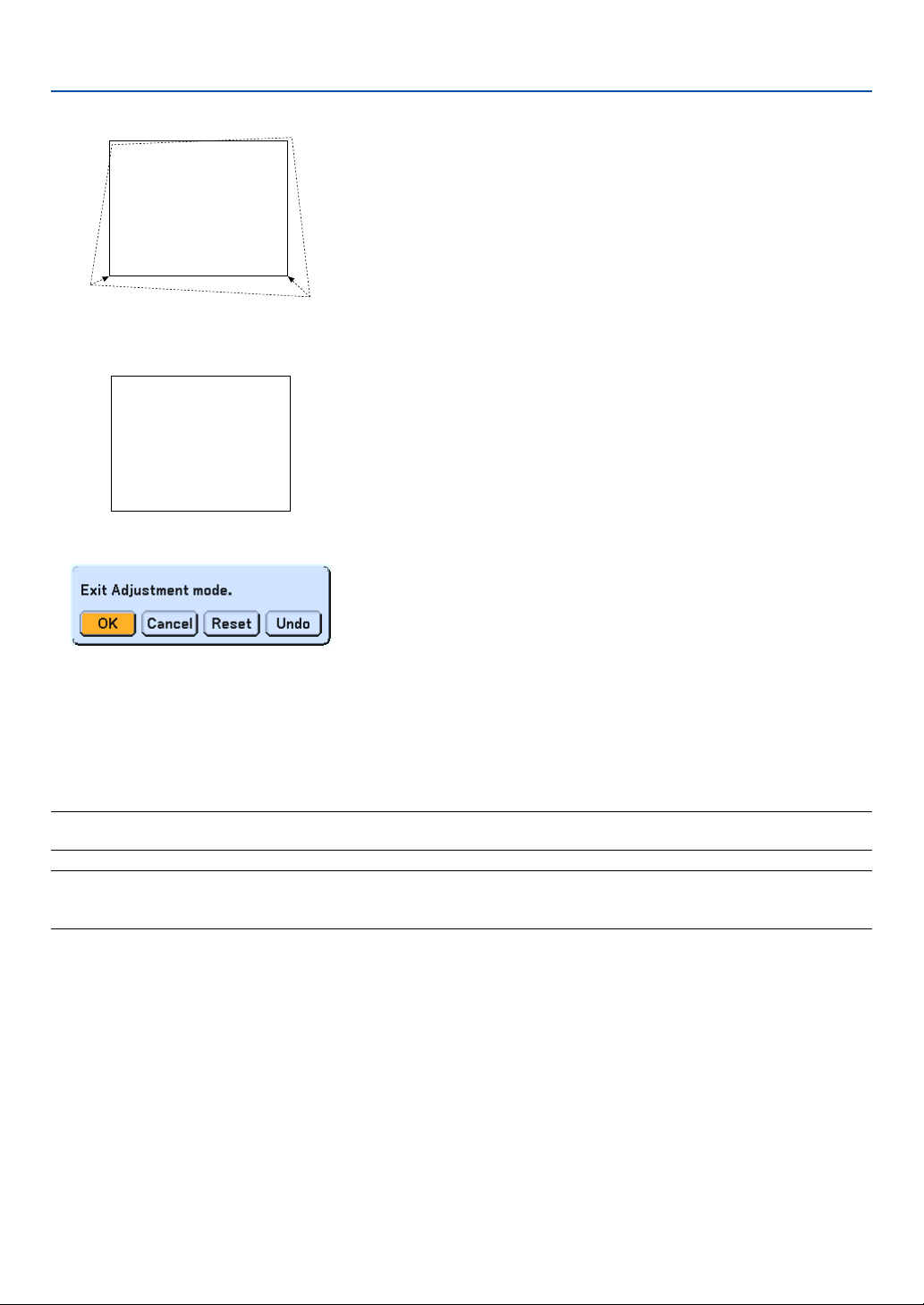
45
Screen
8. Press the ENTER button.
4. Convenient Features
10
.Press the SELECT
왗
or
왘
button to highlight the [OK] and press the ENTER button.
This completes the keystone correction.
Selecting “Cancel” will return to the adjustment screen without saving changes (Step 3).
Selecting "Reset" will return to the factory default.
Selecting "Undo" will exit without saving changes.
NOTE: To return the 3D Reform correction setting values to the factory default, press and hold the 3D REFORM button for a
minimum of 2 seconds.
NOTE: During 3D Reform adjustment, "Aspect Ratio" and "Screen" may not be available. Should this happen, first reset the 3D
Reform data and then do each setting. Second repeat the 3D Reform adjustment. Changing Aspect Ratio and/or Screen setting
can limit 3D Reform in its adjustable range.
Screen
9. Use the SELECT
왖왔왗왘
button to select another icon which points in the direction.
On the Cornerstone adjustment screen, select “Exit” or press the CANCEL button on the remote control.
The confirmation screen is displayed.

46
The adjustable ranges for 3D Reform are as follows:
4. Convenient Features
* The following are conditions under which the maximum angle is achived:
• Image (100") is projected in Wide (Zoom lever)
• Resolution is XGA
Higher resolution than XGA narrows the adjustable range.
• Menu items should be set as follows:
Aspect Ratio ........... 4:3
Screen Type ........... 4:3
• Horizontal and Vertical are adjusted separately.
A combination of both adjustments narrows the adjustable range.
• When "4:3 Fill" is selected in Aspect Ratio, "Cornerstone" and "Horizontal Keystone" are not available.
NOTE:
• If the Cornerstone screen is unavailable (grayed), press and hold the 3D REFORM button for a minimum of 2 seconds to reset
the current correction data. The Cornerstone function becomes available.
•Turning on the projector will reset the previous correction setting values if the projection angle is changed from the last use.
If the projection angle is the same as in the last use, the previous correction setting values are retained in the memory.
To use the previous correction setting values after changing projection angle, select "Manual" in "Keystone" from the menu. See
page 87.
NOTE: The 3D Reform feature can cause an image to be slightly blurred because the correction is made electronically.
Horizontal Vertical
Cornerstone Max. +/– 35° approx. Max. + 56° approx.
Keystone Max. +/– 27° approx.
– 30° approx.
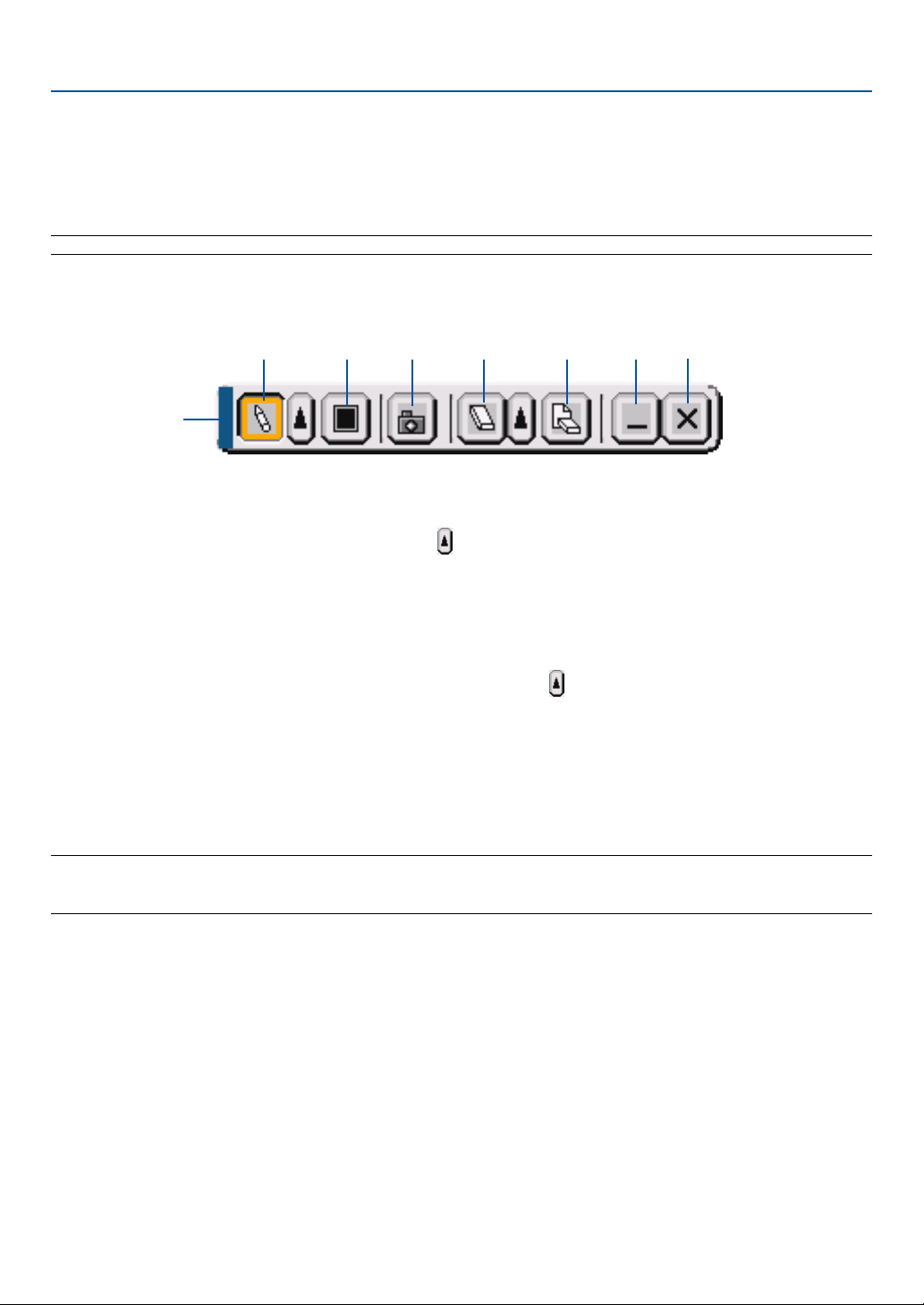
47
4. Convenient Features
쐅 Making Freehand Drawings on a Projected Image
(ChalkBoard)
The ChalkBoard feature allows you to write and draw messages on a projected image.
NOTE: The ChalkBoard feature is available only when a USB three-button mouse is used.
To display or hide the ChalkBoard tool bar, click the middle button on your mouse.
The tool bar contains the following icons.
Drag ................. Drags to move the tool bar.
Pen ................... Left-click and drag to draw. Left-click
or right-click the pen icon to display the pen palette containing four
lines of different thickness from which you can select a line you prefer by left-clicking.
Color ................ Selects a color. Left-click to display the color palette from which you can select a color you prefer by left-
clicking.
Capture............. Left-click to capture a drawing on the ChalkBoard screen and save it to your PC-card inserted into the PC
card slot of the projector.
Eraser ............... Left-click and drag to erase part of a drawing. Left-click or right-click the eraser icon to display the eraser
palette containing four eraser of different thickness from which you can select an eraser you prefer by left-
clicking.
Clear ................. Left-click to clear the drawing completely from the ChalkBoard screen.
Hide .................. Hides the tool bar by left-clicking. Right-clicking anywhere on the screen displays the ChalkBoard tool bar
again.
Exit ................... Clears the complete drawing and exits the ChalkBoard.
NOTE:
• The menu is not available while you display the ChalkBoard screen.
• Selecting another source or switching slides in the Viewer clears a drawing completely.

48
4. Convenient Features
쐈 Storing Images Displayed on the Projector on the PC card or
USB memory (Capture)
The Capture features allows you to capture an image from a source that is currently being displayed. The image is
saved as JPEG in the PC card or USB memory.
NOTE:
• Unless a PC card or USB memory is inserted into the PC Card slot or USB (MOUSE) port of the projector, the Capture feature is
not available.
• The "Card Error" display means that the free space of the PC card or USB memory is insufficient for saving images. Make more
space available on the card by erasing unwanted images with your PC. The number of images that can be captured depends on
the size of the PC card.
• Be sure not to turn off the power or remove the PC card or USB memory while capturing an image. Doing so could cause a
loss of the data in the PC card or USB memory or damage to the card itself.
Preparations:
Insert the PC card into the PC card slot or USB (MOUSE) port of the projector.
Insert the PC card so that the end with the insertion direction arrow on the top goes in first.
* Press the eject button to eject the card.
1. Project the image you wish to store on the projector.
2. Press the FREEZE button on the remote contorol.
3. Press the MENU button to display the Capture menu.
Capture.................. Captures an image and save it as a JPEG file in a PC card or USB memory.
Drive...................... Select the PC Card or USB memory. You can capture an image and save it to your PC card or USB memory.
Exit ........................ Exits the Capture function. Another option to exit the Capture function is to press MENU or CANCEL button
on the remote control or projector cabinet.
NOTE:
Captured images with higher resolution than the projector's native resolution cannot be displayed correctly.
• File size of the captured image varies depending on the resolution of an input signal.
• An hourglass indicating that an image is being captured appears on the projector's display. Do not eject the PC card or turn off
the projector's power while this icon is displayed. Doing so will damage the PC card data. If the PC card data is damaged, use a
computer to repair the data.

49
4. Convenient Features
쐉 Preventing the Unauthorized Use of the Projector
Assigning a keyword prevents the projector from being used by unauthorized individuals.
Assigning a Keyword for the first time
1. Press the MENU button.
The menu will be displayed.
2. Press the SELECT
왘
button twice to highlight the Setup submenu and press the ENTER button.
The page tab “1” will be highlighted.
3. Press the SELECT
왘
button once to highlight the page tab “2”.
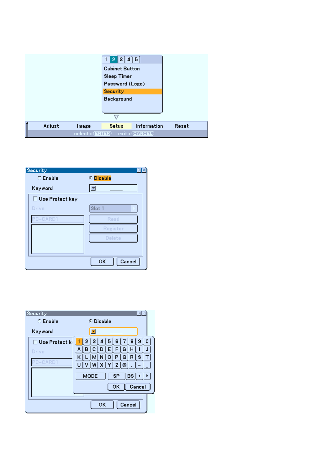
50
4. Convenient Features
4. Press the SELECT
왔
button four times to highlight “Security”.
5. Press the ENTER button to display the Security screen.
6. Press the ENTER
왔
button once to highlight the Keyword entry box and press the ENTER button.
The Software keyboard will be displayed.
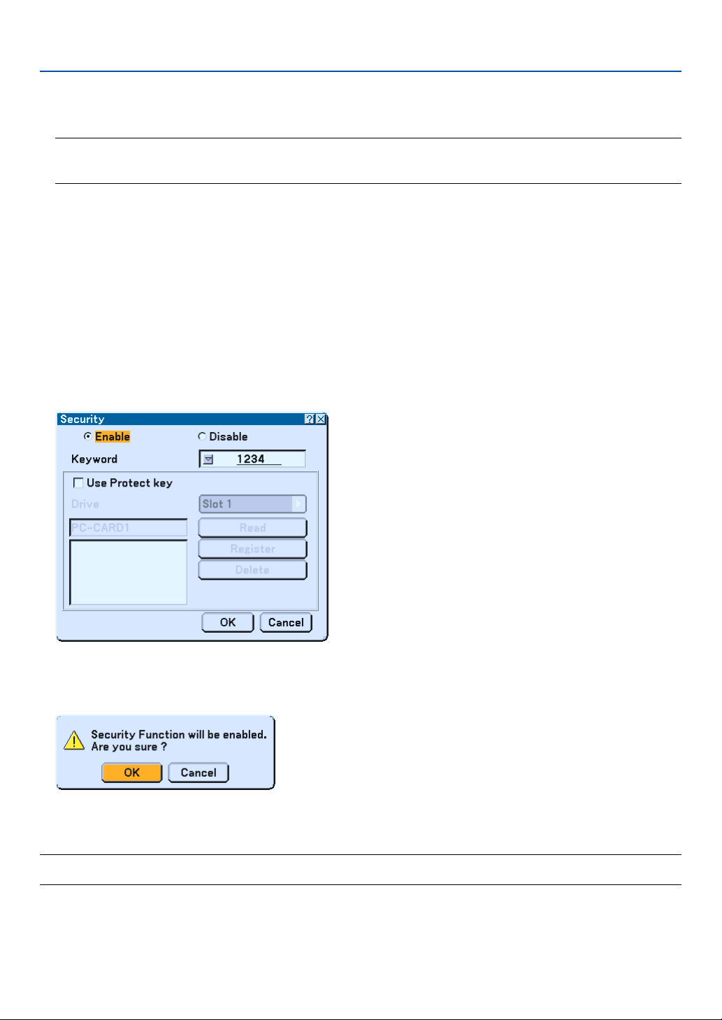
51
4. Convenient Features
7. Enter an alphanumeric keyword using the Software keyboard
For example, to enter “1234”, follow the steps 7-1 to 7-4 below.
NOTE:
• Please make a note of your keyword.
• Do not use spaces (SP) in your keyword.
7-1. Highlight the number “1” and press the ENTER button.
The number “1” will be displayed in the Keyword entry box.
7-2. Press the SELECT
왘
button once to highlight “2” and press the ENTER button.
The number “12” will be displayed in the Keyword entry box.
7-3. For “3” and “4”, use the same procedure as step 7-2.
The number “1234” will be displayed in the Keyword entry box.
7-4. Press the SELECT
왔
button to highlight “OK” and press the ENTER button.
The Software keyboard will disappear.
8. Press the SELECT
왖
button once to highlight “Disable” and press the SELECT
왗
button to highlight
“Enable”.
9. Press the SELECT
왔
button to highlight “OK” and press the ENTER button.
The confirmation screen will be displayed.
10
.Press the ENTER button.
The Security Function is now enabled.
NOTE: A PC card can be used as a protect key. You can skip the keyword entry by inserting a registered PC card when turning on
the projector. See page 91.
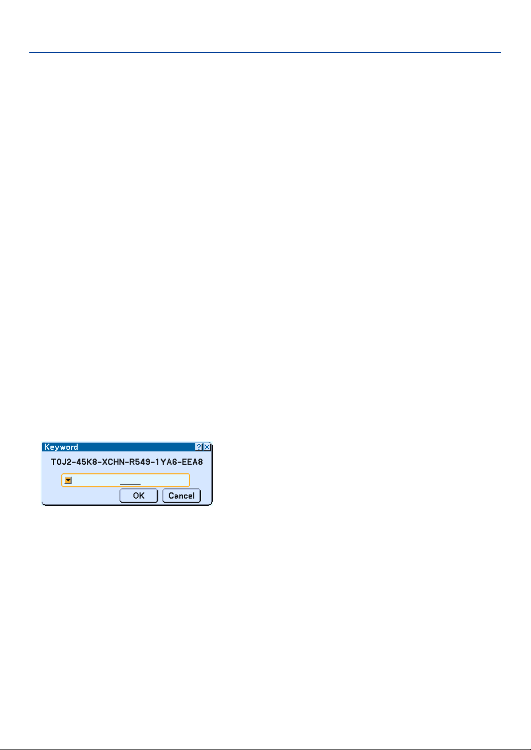
52
Checking If Security is enabled
Tu rn off the projector and turn it back on to check if the Security function is enabled.
1. Press and hold the POWER (ON/STANDBY) button for a minimum of two seconds.
The lamp lights off and the POWER indicator flashes orange. Please wait until the POWER indicator changes
from flashing to steady light.
2. When the POWER indicator lights steady orange, push the Main POWER switch to the off position (O).
The projector will turn off.
3. Push the Main POWER switch to the on position (I).
The POWER indicator lights orange. The projector is in standby condition.
4. Press and hold the POWER (ON/STANDBY) button for a minimum of two seconds.
The projector will turn on. The “Projector is locked! Enter your keyword.” message will be displayed at the bottom
of the screen.
5. Press the MENU button.
The on-screen menu will be displayed.
6. Press the SELECT
왘
button to highlight “Setup” and press the ENTER button.
The page tab “1” will be highlighted.
7. Press the SELECT
왘
button once to highlight the page tab “2”.
8. Press the SELECT
왔
button four times to highlight “Security” and press the ENTER button.
The Keyword entry screen will be displayed
9. Press the ENTER button.
The Software keyboard will be displayed.
10. Use the same procedures as steps 1 to 7 described in the “Assigning a Keyword for the first time”
section to enter “1234”.
Each time one number is entered, an “*” (asterisk) will appear. Keyword appears as asterisks so the real keyword
is hidden.
11. After entering your keyword, highlight “OK” and press the ENTER button.
The Software keyboard will disappear. This will allow you to operate the projector.
4. Convenient Features
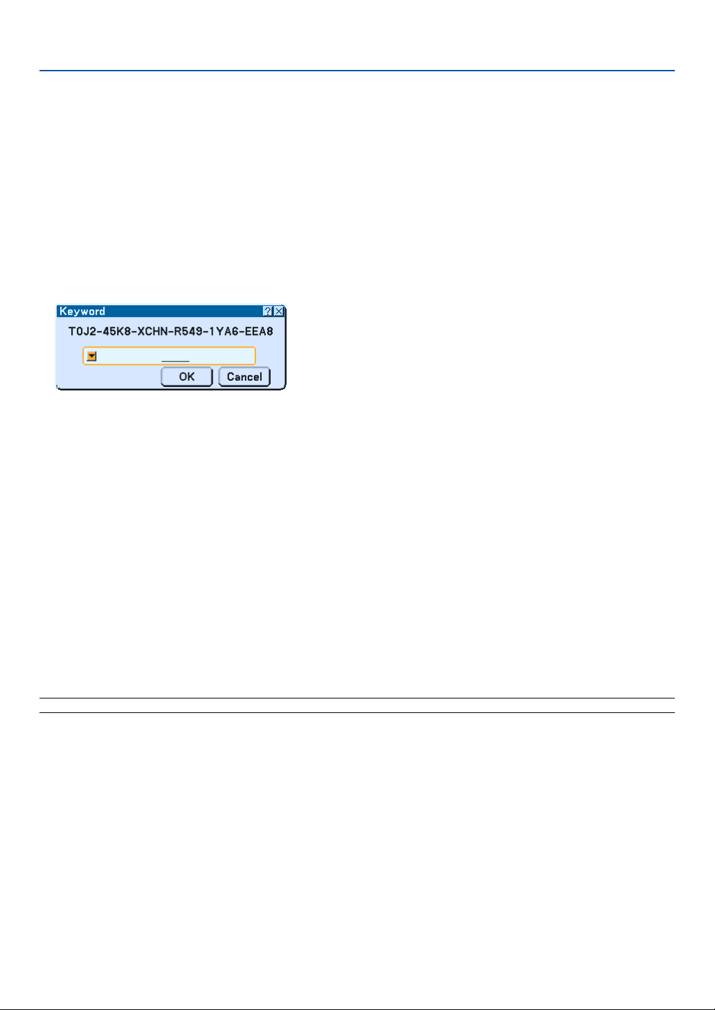
53
Disabling the Security
1. Press the MENU button.
The on-screen menu will be displayed.
2. Press the SELECT
왘
button to highlight “Setup” and press the ENTER button.
The page tab “1” will be highlighted.
3. Press the SELECT
왘
button once to highlight the page tab “2”.
4. Press the SELECT
왔
button four times to highlight “Security” and press the ENTER button.
The Keyword entry screen will be displayed
5. Press the ENTER button.
The Software keyboard will be displayed.
6. Use the same procedures as steps 1 to 7 described in the “Assigning a Keyword for the first time”
section to enter “1234”.
Each time one number is entered, an “*” (asterisk) will appear. Keyword appears as asterisks so the real keyword
is hidden.
7. After entering your keyword, highlight “OK” and press the ENTER button.
The Software keyboard will disappear. The Security screen will be displayed.
8. Highlight “Enable” and press the SELECT
왘
button to highlight “Disable”.
9. Press the SELECT
왔
button to highlight “OK” and press the ENTER button.
The Security Function is now disabled.
NOTE: To enable the Security again, enter your keyword again. Make sure that your keyword is correct.
4. Convenient Features
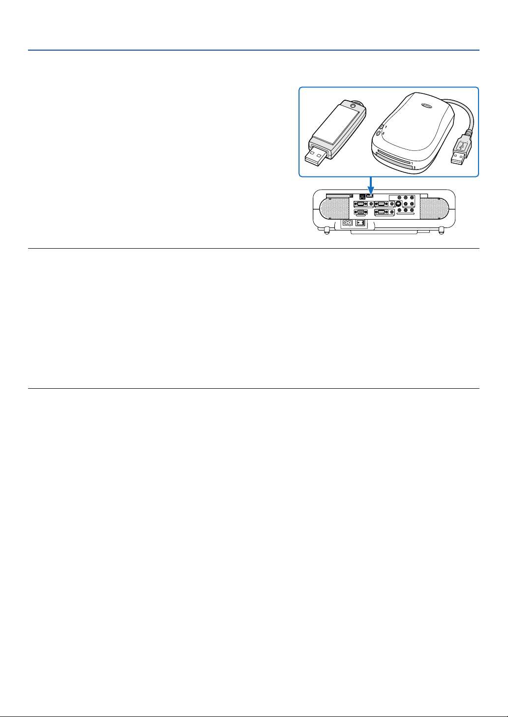
54
4. Convenient Features
씈
Using a USB Memory Device or USB Memory Card Reader
The projector is compatible with either a USB memory device or
USB memory card reader which supports the viewer and security
features.
•To use a USB memory device or USB memory card reader,
connect the device to the USB (MOUSE) port (type A).
• Select one of the drive icons for your USB memory in a pane
on the left side of the Viewer window.
•To use a USB memory device as a Protect key for Security
function, select one from the Drive icons in the Security setting
screen. See page 91.
NOTE:
• Some USB memory devices (brands) or USB memory card readers may not work.
•You cannot use a USB memory device and a USB memory card reader when connecting a USB mouse to the projector.
• Do not do the following while the USB memory device or USB memory card reader’s access indicator is lit or flashing (while
data is being accessed.) Doing so can damage your USB memory device or USB memory card in the reader. Back up your data
in case it will need to be restored.
* Pulling out the USB memory device or USB memory card reader from the USB port of the projector.
* Pulling out the memory card from the USB memory card reader
*Turning off the main power switch or unplugging the power cable.
• The drive for ”USB 1-4” is displayed only when the USB memory device or USB memory card reader is connected to the
projector. The drive for “USB 1-4” may be displayed differently from the one in the USB memory card reader.
• Some USB memory devices (brands) or USB memory cards cannot be used as Protect key for the projector’s Security
function.
AC IN
COMPONENT
Y Cb/Pb Cr/Pr
AUDIO
AUDIO
AUDIO
AUDIO
L/MONO
S-VIDEO
COMPUTER 1AUDIO
PC CARD
USB(COMPUTER)
USB(MOUSE)
MONITOR OUT
COMPUTER 2
PC CONTROL
R
L/MONOVIDEO R

55
5
Using the Viewer
○○○○○○○○○○○○○○○○○○○○○○○○○○○○○○○○○○○○○○○○
Making the Most out of the Viewer Function .............. 56
Operating the Viewer Function from the Projector ..... 58
쐋 Changing Background Logo ...................................... 64

56
5. Using the Viewer
Making the Most out of the Viewer Function
Features
You can view presentation data, capture and play images on the projector. A PC card is used to view presentation data
prepared on the computer and to capture and play images projected with the projector.
The Viewer feature allows you to view slides stored on a PC memory card (referred to as PC card in this manual) or
USB memory on the projector. Even if no computer is available, presentations can be conducted simply with the
projector. This feature is convenient for holding presentations at meetings and in offices, as well as for playing images
taken on digital cameras.
NOTE:
•To use the Viewer, first you need to create presentation materials on your PC (JPEG, BMP, Index* files).
For creating presentation materials using the Dynamic Image Utility 2.0.
* “Index” file is a file created using the Dynamic Image Utility 2.0 contained on the supplied NEC Projector User Supportware
CD-ROM.
See “Using Dynamic Image Utility 2.0 on the supplied CD-ROM” for installing the Dynamic Image Utility 2.0 on your
computer.
Easy to use
• Presentations can be started immediately simply by inserting a PC card or USB memory (not supplied)
• Easy slide switching
• Remote control operation
•Jumping to a list of slides or any specific slide
High quality images
• High resolution up to 1024 x 768 dots
• 24-bit full color playback
• Viewing of digital camera images
Simple utility software (for computer)
• Dynamic Image Utility 2.0 operable on Windows 98/Me/XP/2000
• Slides can be created by capturing the currently displayed image
• Control screen for displaying lists of slides and editing
* Microsoft, Windows and PowerPoint are registered trademarks of Microsoft Corporation.
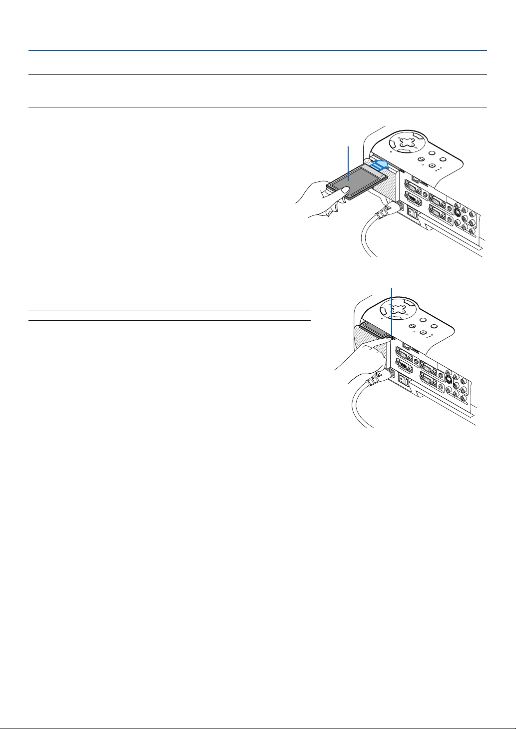
57
Inserting and Removing a PC Card
NOTE:
• Do not try to force the PC card into the slot.
•A dummy card is inserted into the PC CARD slot at the time of shipment. First remove the dummy card before use.
AC IN
3D REFORM
SOURCE
S
E
L
E
C
T
STATUS
LAMP
PC CARD
POWER
ON/STAND BY
AUTO
ADJUST
M
E
N
U
E
N
T
E
R
C
A
N
C
E
L
C
O
M
P
O
N
E
N
T
YC
b
/P
b
C
r/P
r
A
U
D
IO
A
U
D
IO
A
U
D
IO
A
U
D
IO
L
/M
O
N
O
S
-V
ID
E
O
C
O
M
P
U
T
E
R
1
A
U
D
IO
P
C
C
A
R
D
USB(COMPUTER)
USB(MOUSE)
M
O
N
IT
O
R
O
U
T
C
O
M
P
U
T
E
R
2
P
C
C
O
N
T
R
O
L
R
L
/M
O
N
O
V
ID
E
O
R
PC card (not supplied)
Eject button
AC IN
C
O
M
P
O
N
E
N
T
YCb/P
b
C
r/P
r
A
U
D
IO
A
U
D
IO
A
U
D
IO
A
U
D
IO
L
/M
O
N
O
S
-V
ID
E
O
C
O
M
P
UT
E
R 1
AU
D
IO
P
C
C
A
RD
U
S
B
(C
O
M
P
U
TE
R
)
U
S
B
(M
O
U
S
E
)
M
O
NIT
O
R
O
U
T
C
O
M
P
U
TE
R
2
P
C
C
O
N
T
R
O
L
R
L
/M
O
N
O
V
ID
E
O
R
S
T
A
T
U
S
L
A
M
P
P
C
C
A
R
D
P
O
W
E
R
O
N
/S
T
A
N
D
B
Y
E
N
T
E
R
C
A
N
C
E
L
3
D
R
E
F
O
R
M
S
O
U
R
C
E
SELECT
A
U
T
O
A
D
J
U
S
T
M
E
N
U
Inserting the PC Card
• Hold the PC card horizontally and insert it slowly into the
PC card slot with its top facing up.
Removing the PC Card
NOTE: Do not eject the PC card while its data is being accessed.
Press the eject button twice. The PC card pops out a little. Grasp the
edges of the PC card and pull it out.
Direction for Inserting the PC Card
The PC card has a top and bottom and must be inserted into the PC card slot in a specific direction. It cannot be
inserted backwards or upside-down. Attempting to force it into the slot in the wrong direction may break the internal pin
and damage the card slot. Refer to the PC card's operating instructions for the proper direction of insertion.
PC Card Type
The PC Card slot accepts PCMCIA Type II only.
5. Using the Viewer
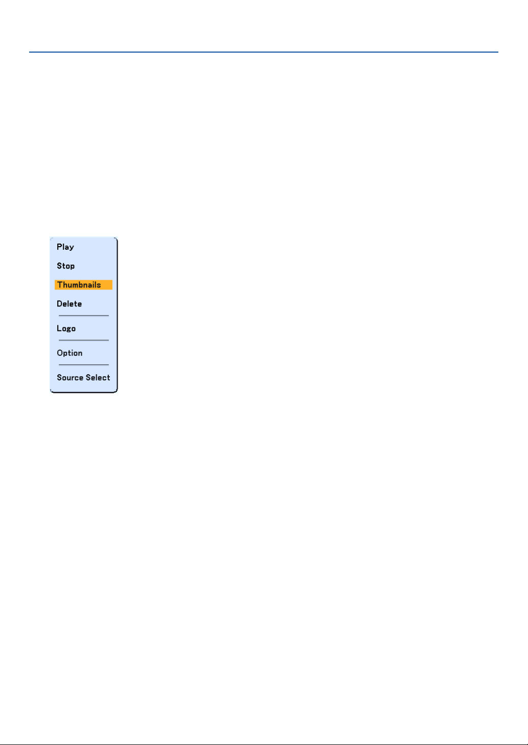
58
5. Using the Viewer
Operating the Viewer Function from the Projector (playback)
This section describes the operation for showing slides created using the Viewer function with the projector. It is also
possible to make slides directly from the images projected with the projector.
Projecting slides (Viewer)
Preparation: Use the Capture feature to store JPEG or BMP files in a PC card or USB memory inserted into the
projector’s slot. Or store JPEG or BMP files in a PC card or USB memory inserted into your PC.
1. Insert a PC card into the PC card slot of the projector.
2. Press the VIEWER button on the remote control or select the “Viewer” from the source list.
An image stored in the PC card will be displayed.
3. Press the MENU button to display the Viewer menu.
The Viewer menu will appear when you press the MENU button on the remote control or the projector cabinet.
The Viewer menu includes the following commands:
Play ................... Plays back automatically or manually depending on the setting in Option. This allows you to move on to the
next slide when "Manual Play" is selected in the “Play Mode”.
Stop ................... This allows you to stop Auto Play while you are playing back and to resume playing from the selected slide
or folder when "Auto Play" is selected in the “Play Mode”.
Thumbnails........ Displays a list of thumbnails of JPEG or BMP files stored in the PC card inserted into the projector.
Delete ................ Deletes a captured slide(s) or all the captured slides in the Capture - specific folder.
Logo .................. Replace the default background logo with another logo in JPEG or BMP format.
Option................ Displays the Viewer setting options.
Source Select .... Displays the Source list.
4. Select “Play” and then press the ENTER button to display the first slide or to start playing slides auto-
matically.
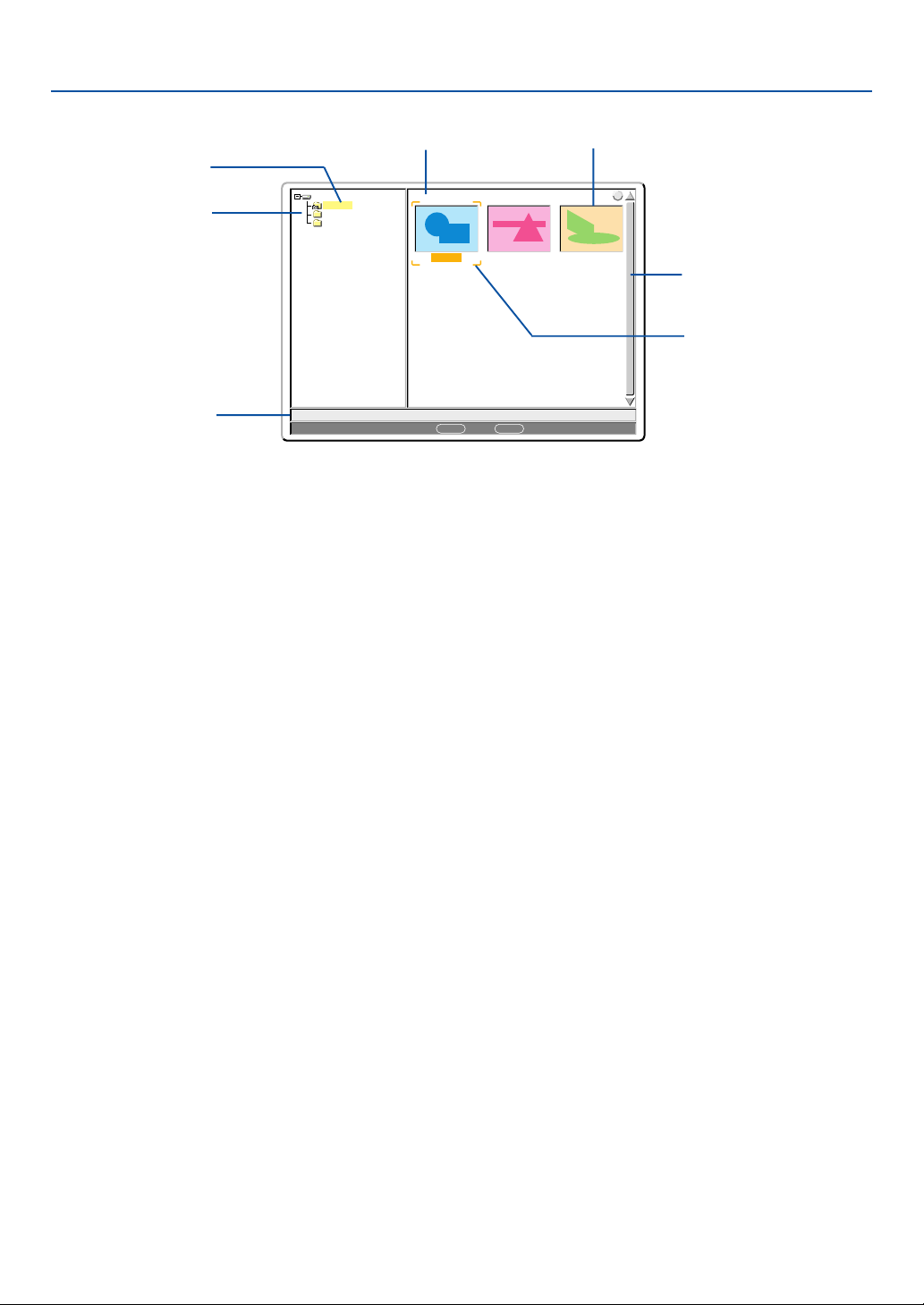
59
5. Using the Viewer
0000.jpg 0001.jpg 0002.jpg
3 Files
Slot 1
_CAP_
_RESTORE
RECYCLED
1/3 0000.jpg 60KB
select : ENTER folder :
CANCEL
?
Highlight .................................. Indicates the selected folder or drive.
List of folders .......................... Indicates folders contained on a PC card or USB memory.
Information .............................. Indicates information of the selected file or folder
Folder: folder name, creation date, creation time
File: slide number/number of displayable slides in a folder, file name, creation date, creation time,
file size
Number of files ........................ Indicates number of displayable slides in the selected folder. The maximum number of images
recognized as slides within one directory is 128.
Thumbnail/file name ................ Indicates thumbnails and names contained in a folder.
Cursor ..................................... Indicates the selected slide.
Scroll bar ................................. Uses to view folders or files not visible in the window.
Viewer Window Elements
Highlight
List of folders
Information
Number of files
Thumbnail/file name
Scroll bar
Cursor (orange)
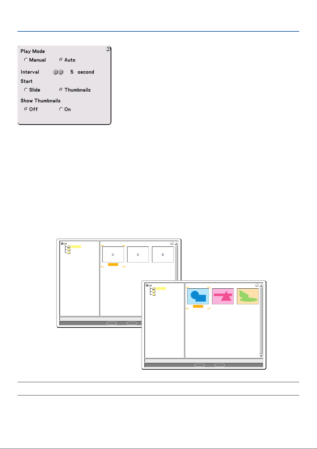
60
5. Using the Viewer
NOTE: If no memory card is inserted in the PC CARD slot, there is no signal, and a black, blue or logo background is displayed,
depending on the setting. Playback is stopped when
왗왘
button on the cabinet or remote control is pressed in Auto Play mode.
Setting Option for Viewer
Play Mode:
Manual .................. Views a slide manually when the Viewer source is selected.
Auto ...................... Plays back slides automatically when the Viewer source is selected.
Interval:
Specifies interval time between 5 and 300 seconds.
Start:
Specifies start screen when the Viewer source is selected.
Show Thumbnails:
Selecting the Viewer source will display a list of thumbnails of JPEG or BMP files stored in the PC card or USB
memory when “On” is selected.
0000.jpg 0001.bmp 0002.jpg
3 Files
Slot 1
_CAP_
_RESTORE
RECYCLED
1/3 0000.jpg 60KB
select : ENTER folder :
CANCEL
?
0000.jpg 0001.jpg 0002.jpg
3 Files
Slot 1
_CAP_
_RESTORE
RECYCLED
1/3 0000.jpg 60KB
select : ENTER folder :
CANCEL
?
“Off”
“On”

61
Switching to Slides Directly from Other Input Modes
With this function it is possible to switch directly to a slide when the picture of a VCR or computer is being projected.
Example: When conducting presentations using a combination of slides and moving pictures from a VCR, etc., it is
possible to switch from a Viewer slide to the video picture then back to the Viewer slide simply by using the Viewer
button.
NOTE: Even if you switch the current Viewer source to another source, the current slide is retained. When you return back to the
Viewer, you will get the slide that has been retained.
Viewing Digital Images
Digital images can be played with the Viewer if the following conditions are met:
• If the image can be stored on an MS-DOS format PC card.
• If the image can be stored in a format supported by the Viewer. With the Viewer, images on the card are
searched for in directories and images in JPEG or BMP format are recognized as slides. Searchable directories
are directories within two steps from the root directory, and searchable images are images within the first 12
files in the directory. Only file and slide switching are possible.
NOTE: The maximum number of images recognized as slides within one directory is 128.
5. Using the Viewer
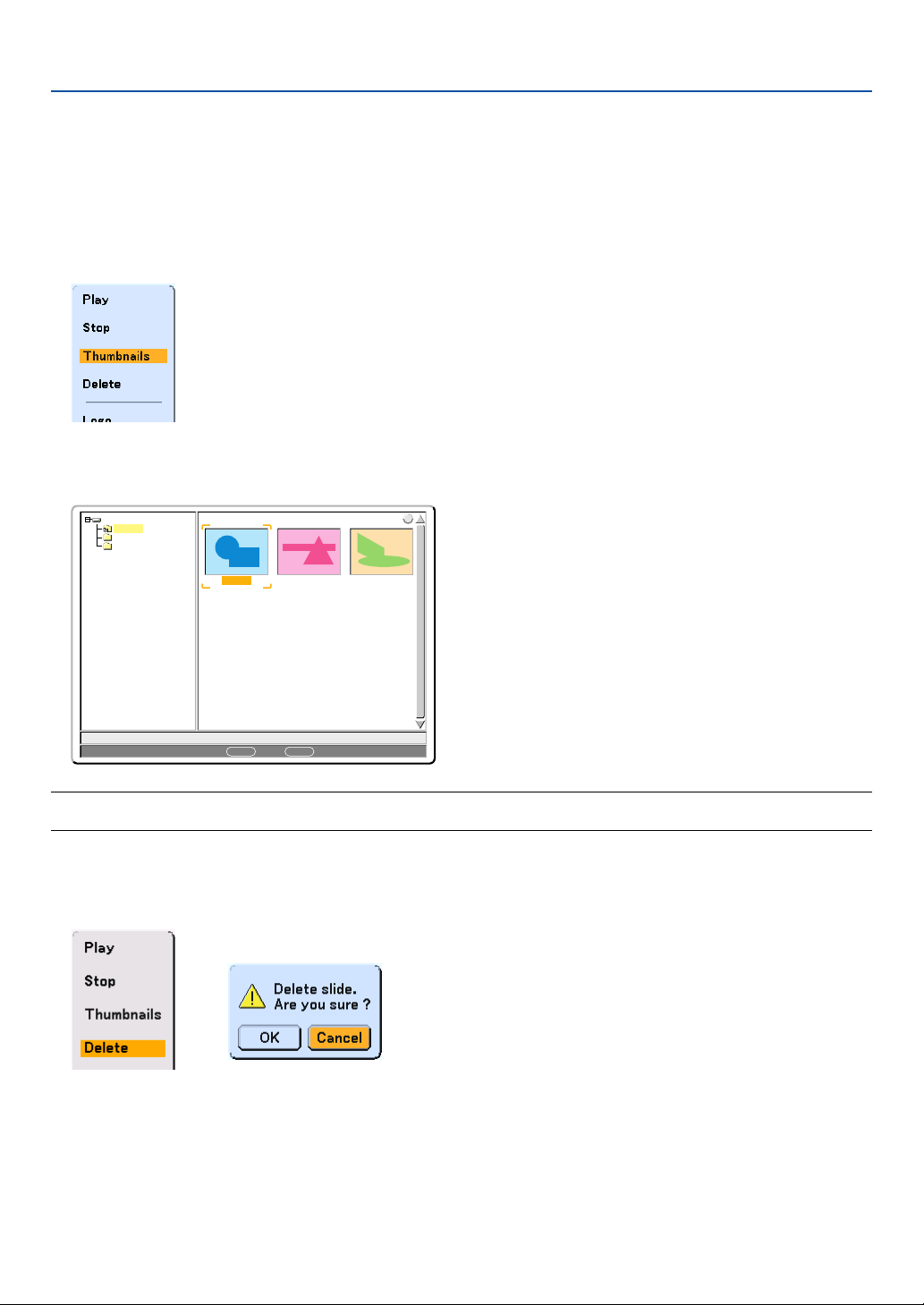
62
5. Using the Viewer
Deleting Captured Images
Using the Delete command on the Viewer menu allows you to delete captured images.
To delete captured images:
Preparation: Make sure that the PC card is inserted into the PC card slot of the projector.
1. Press the VIEWER button on the remote control to display an image.
2. Press the MENU button to display the Viewer menu.
0000.jpg 0001.jpg 0002.jpg
3 Files
Slot 1
_CAP_
_RESTORE
RECYCLED
1/3 0000.jpg 60KB
select : ENTER folder :
CANCEL
?
3. Use the
왔
button to select “Thumbnails” and then press the ENTER button.
The Thumbnail screen will be displayed.
NOTE: To change highlight from the Thumbnails screen (pane on the right) to a directory tree (pane on the left) , press the
CANCEL button. To return highlight to the Thumbnails screen, press the ENTER button.
4. Use the
왖왔왗왘
buttons to select an image you wish to delete.
5. Press the MENU button to display the Viewer menu.
6. Use the
왔
button to select “Delete” and then press the ENTER button.
A confirmation message will be displayed.
7. Use the
왗
button to select “OK” and then press the ENTER button.
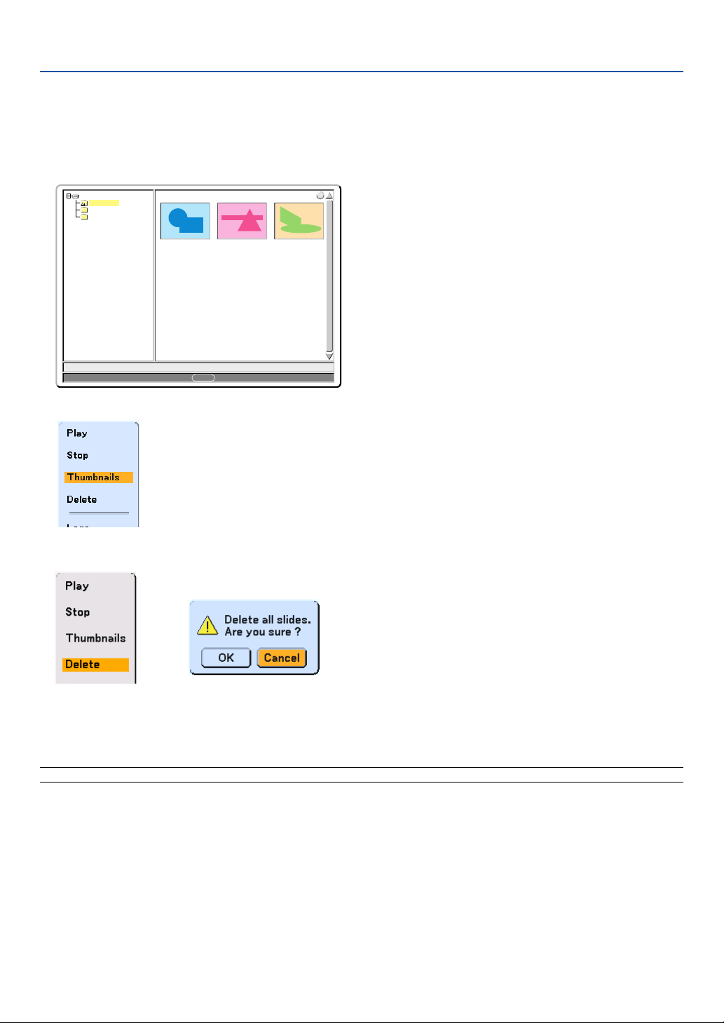
63
5. Using the Viewer
This completes deleting.
To delete all the captured images:
1. Repeat steps 1 to 3 in the above described procedure.
2. Press the CANCEL button to select the “__CAP__” folder in the directory (pane on the left).
0000.jpg 0001.jpg 0002.jpg
3 Files
Slot 1
__CAP__
_RESTORE
RECYCLED
1/3 0000.jpg 60KB
select : ENTER
?
3. Press the MENU button to display the Viewer menu.
4. Use the
왔
button to select “Delete” and then press the ENTER button.
5. Use the
왗
button to select “OK” and then press the ENTER button.
This completes deleting.
NOTE: The vacant "__CAP__" folder stays even after you delete all the captured images.
A confirmation message will be displayed.
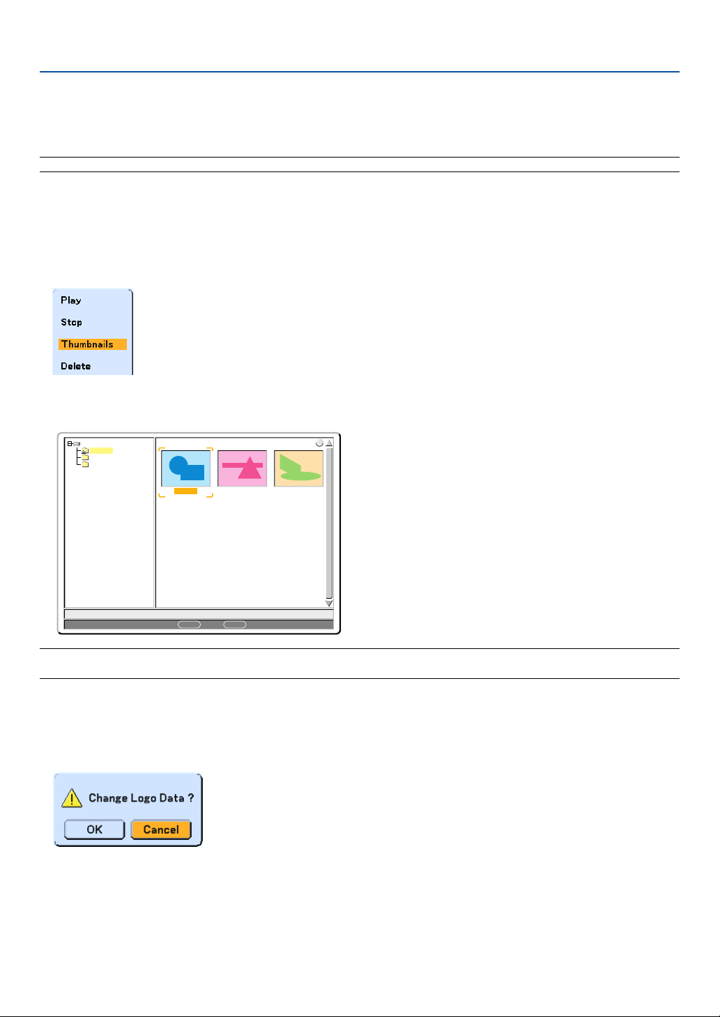
64
5. Using the Viewer
Changing Background Logo
You can change the default background logo using the Viewer feature.
NOTE: File size must be 256KB or less. Other file formats than JPEG and BMP are not available.
Preparation:
Use the Capture feature to store JPEG or BMP files in a PC card inserted into the projector’s slot. Or store JPEG
or BMP files in a PC card inserted into your PC’s slot and insert the PC card into the projector’s slot.
1. Press the VIEWER button on the remote control to display an image.
2. Press the MENU button to display the Viewer menu.
0000.jpg 0001.jpg 0002.jpg
3 Files
Slot 1
_CAP_
_RESTORE
RECYCLED
1/3 0000.jpg 60KB
select : ENTER folder :
CANCEL
?
3. Use the
왔
button to select “Thumbnails” and then press the ENTER button.
The Thumbnail screen will be displayed.
NOTE: To change highlight from the Thumbnails screen (right window) to a directory tree (left window) , press the CANCEL
button. To return highlight to the Thumbnails screen, press the ENTER button.
4. Use
왖왔왗왘
button to select a JPEG or BMP file (slide) for your background logo.
5. Press the MENU button to display the Viewer menu.
6. Use the
왔
button to select "Logo" and then press the ENTER button.
A confirmation dialog box will be displayed.
7. Use the
왗
button to select “OK” and press the ENTER button. This completes changing a logo for the
background.
* Once you have changed the background from the NEC logo to another, you cannot return the logo to back-
ground even by using “Reset”.

65
6
Using Dynamic Image Utility 2.0
on the supplied CD-ROM
○○○○○○○○○○○○○○○○○○○○○○○○○○○○○○○○○○○○○○○○
End User License Agreement................................... 66
Introduction ............................................................... 67
Operating Environment ............................................. 68
Equipment Connections and Settings ...................... 69
Software Installation ................................................. 69
Starting/Exiting the Software .................................... 70
Troubleshooting ........................................................ 72
(English version only)

66
6. Using Dynamic Image Utility 2.0 on the supplied CD-ROM
Be sure to read this before installing and using the accompanying software.
END USER LICENSE AGREEMENT
PLEASE READ THIS SOFTWARE LICENSE AGREEMENT ("LICENSE") CAREFULLY BEFORE INSTALLING THE
SOFTWARE. IT PROVIDES THE TERMS OF THIS LICENSE.
WHILE INSTALLING THE SOFTWARE, THIS SOFTWARE LICENSE AGREEMENT WILL BE DISPLAYED. BY CLICK-
ING ON THE "Yes" BUTTON, YOU ARE CONSENTING TO BE BOUND BY THIS AGREEMENT. FOLLOW THE
DIRECTIONS ON THE SCREEN AND COMPLETE THE INSTALLATION PROCESS.
IF YOU DO NOT AGREE TO ALL OF THE TERMS OF THIS AGREEMENT, CLICK THE "No" BUTTON. THE INSTAL-
LATION PROCESS WILL NOT CONTINUE.
NEC Viewtechnology,Ltd.("NECVT") grants you ("User") a license to use the NEC PROJECTOR USER SUPPORTWARE
("Software") provided with this End User License Agreement ("EULA"). User assumes responsibility for the selection,
adoption use and the result of use of the Software to achieve its intended result.
1. Term
1) EULA will become effective upon User's agreement to the terms of EULA and shall remain in force until User
terminates it by returning or destroying the Software and its related documents.
2) Notwithstanding the foregoing NECVT may terminate EULA at any time upon User failing to abide by any terms
of EULA. Upon the termination of the EULA by NECVT, the license granted to User shall be terminated automati-
cally. User agrees to destroy the Software together with all copies of it upon such termination.
2. License
User use the Software on personal computers only for operating NECVT's projector supplied with the Software or
other projector to be specified by NECVT("Projector")
3. Replication, modification and merger of the Software
1) User may make copies of the Software and related documentation to the extent necessary for using the Projec-
tor. User agrees to reproduce the NECVT's copyright notice and other notice on any such copies.
2) User may not use, copy, modify, or otherwise dispose of the Software, except as expressly permitted in EULA.
3) No provision in EULA shall be construed to assign and/or transfer any intellectual property right in the Software
to User.
4. Transfer of the Software
1) User may transfer the Software to any third party, provided always that:
a) User must transfer, with the Software, to such third party EULA and all the related
documentation with all copies thereof, and must not retain any copy thereof.
b) Such third party has agreed to the terms and conditions of EULA.
2) Except as otherwise expressly permitted above, User may not sublicense, assign, transfer or otherwise dispose
of the license for the Software.
5. Reverse Engineering
User may not reverse engineer, decompile, and/or disassemble the Software, except and only to the extent that such
activity is expressly permitted by applicable law notwithstanding this limitation.
6. Limitations of Warranty
1) Except as expressly specified herein, the Software is provided "as is" without warranty of any kind, including but
not limited to implied warranties for fitness for a particular purpose, merchantability, title and non-infringement of
any third party rights.
2) If User finds a material defect, which effects to the proper operation of the Software, in the media of the Soft-
ware, NECVT will replace such defective media at no charge, if such media is returned to distributor from which
such User purchased it within 1 month from such purchase and if NECVT determines that such defect is due to
NECVT.

67
7. Limitations of Liability
In no event shall NECVT be responsible for any indirect, consequential or special damages or lost profits even if
NECVT has been advised of the possibility of such damages, and/or for any claim for compensation or damage by any
third party to User.
8. Others
1) The validity, interpretation, construction and performance of EULA shall be governed by the laws of Japan.
2) User shall not export the Software to any country to which such export would be prohibited by any applicable
laws.
Introduction
Thank you for your purchase of the NEC portable projector (hereafter referred to as "unit" or "projector").
This projector is connected to a personal computer or other equipment and clearly projects text or graphics to a
screen.
This projector is supplied with convenient software that allows presentations to be made more simply and effectively.
This guide gives an overview and describes the use of the accompanying software (contained in the CD-ROM that is
supplied with this projector). Look over this guide in conjunction with the Help functions of the software programs.
Contents of the Supplied CD-ROM
The supplied CD-ROM contains the following software programs:
• Dynamic Image Utility 2.0
• Viewer PPT Converter 2.0
• Image Express Utility 1.0 (not available on this model)
Please see the Help functions of the software programs for information about their functions and operation.
What Can Be Accomplished with the Supplied Software
Dynamic Image Utility 2.0
• Converts PowerPoint files, JPEG images, and other files and creates slides that can be displayed with the viewer
function of the projector.
• Captures portions of the image from the screens of word processors, spreadsheets, browsers, and other pro-
grams for use in presentations.
• By saving the created slides on a flash memory card (*) and inserting the card into the PC Card slot of the
projector, the slides can be projected to the screen without connecting a personal computer.
* Please purchase a commercially available PCMCIA Type 2 (ATA specification) flash memory card.
• The connection of personal computers and projectors by means of connection with serial cable (*) allows the
following uses.
* A network connection is not abailable on this model.
(1) Images and slides can be sent from the personal computer to the projector and then projected to the screen.
When using Microsoft PowerPoint 2000/2002, slides can be sent synchronized with the slide show page feed.
(2) A personal computer can be used to switch the projector power on/off, control the adjustment of image
quality and other settings, and to display the remaining lamp life.
Viewer PPT Converter 2.0
• Converts files created with Microsoft PowerPoint 95/97/2000/2002 to an independent index format with a simple
operation to enable direct playback with the viewer function of the projector.
• When using Microsoft PowerPoint 2000/2002, Viewer PPT Converter 2.0 can be started from PowerPoint (by
means of add-in registration to PowerPoint).
6. Using Dynamic Image Utility 2.0 on the supplied CD-ROM

68
6. Using Dynamic Image Utility 2.0 on the supplied CD-ROM
Image Express Utility 1.0 (not available on this model)
• Using a network environment, this program enables the screen image displayed by the personal computer to be
sent to the projector and then projected to a screen.
•Two methods are available for sending the screen image to the projector. "Continuous Transmit" automatically
sends the screen image of the personal computer at a fixed interval. "Single Frame Transmit" sends the screen
image by clicking the screen button (or pressing a key).
Information about Upgrading this Software
Please see the service page for NEC projectors (http://www.nec-pj.com/) for information about software upgrades of
NEC Projector User Supportware (i.e., Dynamic Image Utility and Viewer PPT Converter).
Operating Environment
Supported Equipment
CPU
Memory
Supported OS
Resolution
Screen Colors
IBM PC/AT compatible computers
• CD-ROM drive a requirement (at time of installation)
Pentium MMX processor or higher a requirement
Pentium III 800 MHz or higher recommended
For Windows XP
• 128 MB or more a requirement
• 192 MB or more recommended
For other operating systems
• 64 MB or more a requirement
• 128 MB or more recommended
쏄 More memory may be necessary when other applications are run at the same time.
Windows 98
Windows 98 Second Edition
Windows Me
Windows 2000 Professional
Windows XP Home Edition
Windows XP Professional/Windows XP Tablet PC Edition
* Microsoft Internet Explorer 5.01 or higher is required for the aforementioned environments.
* Does not support Windows power-saving function.
1024 dots x 768 lines recommended
High Color (15 bit, 16 bit)
True Color (24 bit, 32 bit)

69
6. Using Dynamic Image Utility 2.0 on the supplied CD-ROM
Equipment Connections and Settings
When Making Connections with Serial Cable
What Can Be Accomplished
• Using Dynamic Image Utility 2.0, a picture or slide can be sent to the projector and then projected to a screen.
• Using the projector control function of Dynamic Image Utility 2.0 allows operations to be performed from the per-
sonal computer which include switching the projector power on/off, signal selection, and adjustment of the picture
quality.
[For Connections with Serial Cable]
Equipment to Be Prepared
• Projector (This unit)
•Personal computer
• Serial cable not included with the projector (Optional CA03D is available)
Connection at the Projector Side
Plug the serial cable into the PC CONTROL connector. (“Terminal Panel Features” and “PC Control Connector” on
pages 16 and 119)
Connection at the Personal Computer Side
Plug the serial cable into the (RS-232C) serial connector.
Software Installation
NOTE
• Windows 98 operations will be described in examples given here.
• When using Windows 2000, please perform software installation/uninstalling with "Administrators" authority. When using Win-
dows XP, perform with "Computer Administrator" authority.
Dynamic Image Utility 2.0 Installation
Dynamic Image Utility 2.0 and Viewer PPT Converter 2.0 will all be installed together. The various programs cannot be
installed individually.
Preparation:
Start Windows.
If Windows has already been started, please exit all running application software. The installation may not be com-
pleted properly unless all software has been exited.
1.Place the supplied CD-ROM in the CD-ROM drive.
The "Startup" screen will appear.
Reference
Should the "Startup" screen not appear...
1) Click [Start].
2) Click [Run (R)]. The [Run] screen will appear.
3) Enter the CD-ROM drive name (e.g., "Q: \") and then "SETUP.EXE" to [Open (O)].
4) Click [OK]. The "Startup" screen will appear.

70
2.Click "Please read this first" and read the Readme about Dynamic Image Utility 2.0.
3.Click "Installing the Dynamic Image Utility 2.0".
The “Welcome” screen will appear.
4.Click [Next >] at the "Welcome" screen.
The "End User License Agreement" screen will appear.
Please carefully read the contents of the "End User License Agreement".
5.If you agree, click [Yes].
If you do not agree, please click [No] and exit the installer.
6.Now, follow the operations described in the screen messages.
To cancel the installation of the supplied software part way through the installation, click [Cancel] and follow the
instructions of the dialog box.
Please remove the CD-ROM from the CD-ROM drive when the installation is completed.
Uninstalling
Dynamic Image Utility 2.0 and Viewer PPT Converter 2.0 will all be uninstalled together. The various programs cannot
be uninstalled individually.
1.Click [Start].
2.Click [Settings]
→
[Control Panel].
The "Control Panel" screen will be displayed.
3.Double click [Add/Remove Programs].
The "Add/Remove Programs Properties" screen will appear.
4.Click "Dynamic Image Utility 2.0" from the list.
5.Click [Add/Remove. . . ].
The "Confirm File Deletion" screen will appear.
6.Check the message and click [Yes].
7.Now, follow the operations described in the screen messages.
When the uninstall procedure is completed, there will be a return to the "Add/Remove Programs Properties" screen.
8.Click [OK].
There will be a return to the "Control Panel" screen
Starting/Exiting the Software
Dynamic Image Utility 2.0
Start the Software
Preparation:
Install the software on the personal computer from the supplied CD-ROM. (Page 69)
The software cannot be started from the supplied CD-ROM.
From the [Start] menu click [Program] → [NEC Projector User Supportware] → [Dynamic Image Utility 2.0].
Dynamic Image Utility 2.0 will start.
Reference
• By selecting a PowerPoint file with Dynamic Image Utility 2.0 and clicking [Tools] → [Converting PowerPoint file], the
function equivalent to Viewer PPT Converter 2.0 can be executed.
6. Using Dynamic Image Utility 2.0 on the supplied CD-ROM

71
6. Using Dynamic Image Utility 2.0 on the supplied CD-ROM
Display Help
Preparation:
Please start Dynamic Image Utility 2.0.
1.Click [Help].
The [Help] menu will appear.
2.Click [Help].
The [Help] screen will appear.
Exit the Software
1.Click [File].
The [File] menu will appear.
2.Click [Exit].
Dynamic Image Utility 2.0 will close.
Viewer PPT Converter 2.0
Start the Software
Preparation:
(1) Check that Microsoft PowerPoint has been installed. Viewer PPT Converter 2.0 cannot be used unless PowerPoint
has been installed.
(2) Install the software on the personal computer from the supplied CD-ROM. (Page 69)
The software cannot be started from the supplied CD-ROM.
1.From the [Start] menu click [Program]
→
[NEC Projector User Supportware]
→
[Viewer PPT Converter 2.0].
Dynamic Image Utility 2.0 will start.
Reference
•A function equivalent to Viewer PPT Converter 2.0 can also be executed from the Dynamic Image Utility 2.0
[Tools]
→
[Converting PowerPoint file] menu.
• Viewer PPT Converter 2.0 can also be started from the Microsoft PowerPoint 2000/2002 [Tools]
→
[NEC Projec-
tor User Supportware]
→
[Output Viewer] menu.
Display Help
Preparation:
Please start Viewer PPT Converter 2.0.
1.Click [Help].
The [Help] menu will appear.
Exit the Software
1.Click [Exit].
Viewer PPT Converter 2.0 will close.
72
6. Using Dynamic Image Utility 2.0 on the supplied CD-ROM
Troubleshooting
In this section, the software names have been abbreviated as follows:
Dynamic Image Utility 2.0 to DIU 2.0 and Viewer PPT Converter 2.0 to PPTC 2.0.
<Problem> Installation does not complete normally.
Check Points
Countermeasures
When using Windows 2000, did you log on with "Administra-
tors" authority? When using Windows XP, did you log on with
"Computer Administrator" authority?
When using Windows 2000 or Windows XP, log on with the
authority described at the left and then install.
Has Microsoft PowerPoint 2000/2002 been installed on the
personal computer to which this projector software is being
installed?
When this projector software is installed on a personal
computer that does not have PowerPoint 2000/2002 installed,
a message to the effect of "Error in the automatic registration of
PPTViewer2.dll" will appear part way through the installation.
When the message described at the left appears part way
through the installation, add-in registration will not be made to
PowerPoint; however, the installation of this projector software
will be completed normally.
To have add-in registration made to PowerPoint, please install
this projector software to a personal computer on which
PowerPoint 2000/2002 has been installed.
<Problem> Viewer PPT Converter 2.0 does not function. (PPTC 2.0)
Check Points
Countermeasures
Has Microsoft PowerPoint been installed on the personal
computer?
Install PowerPoint on the personal computer. Or, install Viewer
PPT Converter 2.0 on a personal computer on which
PowerPoint has been installed.
<Problem> When using the projector control function, the projector power does not switch on. (DIU 2.0)
Check Points
Countermeasures
Are the personal computer and the projector connected by a
serial cable?
Connect the personal computer and the projector with an serial
cable.
<Problem> You want to delete the PowerPoint add-in registration. (PPTC 2.0)
Check Points
Countermeasures
Installing this projector software when Microsoft PowerPoint
2000/2002 has already been installed on the personal
computer, will result in the automatic registration of the add-in
to PowerPoint.
Please see the PowerPoint Help function for the method of
deleting PowerPoint add-in registrations.
The PowerPoint add-in registration will not be deleted even
when this projector software is uninstalled.

73
7
Using On-Screen Menu
○○○○○○○○○○○○○○○○○○○○○○○○○○○○○○○○○○○○○○○○
Using the Menus........................................................ 74
Menu tree .................................................................. 75
Menu Elements.......................................................... 77
Menu Descriptions & Functions [Adjust] .................... 78
Menu Descriptions & Functions [Image] .................... 82
Menu Descriptions & Functions [Setup] .................... 85
Menu Descriptions & Functions [Information] .......... 100
Menu Descriptions & Functions [Reset] .................. 101
Entry List ................................................................. 102
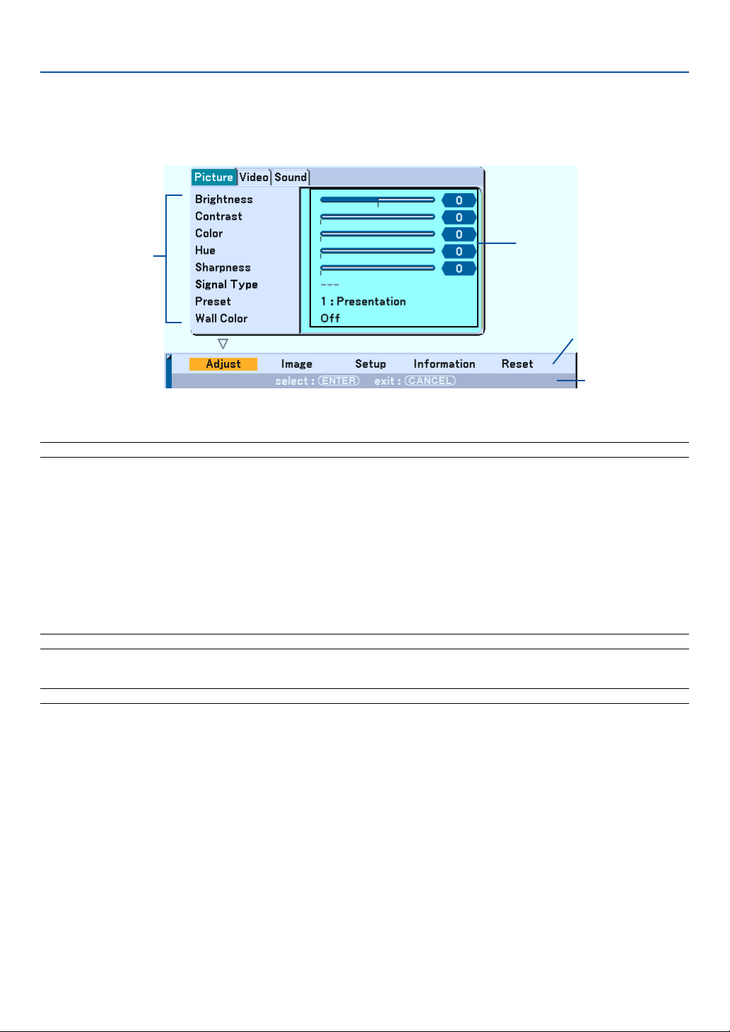
74
Using the Menus
1. Press the MENU button on the remote control or the projector cabinet to display the menu.
The Picture menu will be displayed (factory preset).
NOTE: The commands such as
왗왘
, ENTER, CANCEL in the gray bar show available buttons for your operation.
2. Press the SELECT
왗왘
buttons on the remote control the projector cabinet to display the submenu.
3. Press the ENTER button on the remote control or the projector cabinet to highlight the top item or the
first tab.
4. Use the SELECT
왖왔
buttons on the remote control or the projector cabinet to select the item you want
to adjust or set.
You can use the SELECT
왗왘
buttons on the remote control or the projector cabinet to select the tab you
want.
NOTE: You can select a tab only when the tab color is orange.
5. Press the ENTER button on the remote control or the projector cabinet to display the submenu window.
NOTE: You can also display a submenu window by pressing the SELECT
왘
button.
6. Adjust the level or turn the selected item on or off by using the SELECT
왖왔왗왘
buttons on the remote
control or the projector cabinet.
7. Press the ENTER button or the CANCEL button on the remote control or the projector cabinet.
Changes are stored until you adjust it again.
ENTER ................... Stores changes.
CANCEL ................. Returns to the previous screen without storing changes.
8. Repeat steps 2 -7 to adjust an additional item, or press the CANCEL button on the remote control or the
projector cabinet to quit the menu display.
Main menu
Submenu window
Currently available
buttons
Submenu
7. Using On-Screen Menu

75
Menu tree
7. Using On-Screen Menu
Menu Item
Adjust Picture Brightness
Contrast Manual/Auto
Color
Hue
Sharpness
Signal Type RGB, Component
Preset 1 to 5
Detail Settings Reference Presentation, Video, Movie,
Graphic, sRGB
Gamma Correction
Dynamic, Natural, Black Detail
Color Temperature
5000, 6500, 7200, 7800, 8500, 9300
White Balance Brightness RGB, Contrast RGB
Color Correction Red, Green, Blue,
Cyan,Magenta,Yellow
Wall Color Off, Blackboard, Light yellow, Light green, Light blue, Sky blue, Light rose, Pink
Video Noise Reduction Low, Medium, High
Color Matrix HDTV, SDTV
Y/C Delay 0 to 15
3D Y/C Separation Motion Control On/Off On: Still, Normal, Movie
Vertical Enhancer Off, 1, 2, 3
I/P Converter Deinterlace(Auto/Still), Interlace
Sound Bass -15 to +15
Treble -15 to +15
Image Aspect Ratio 4:3 4:3, Letterbox, Wide Screen, Crop
16:9 4:3 Window, Letterbox, Wide Screen, 4:3 Fill
Pixel Adjust Clock
Phase
Position Horizontal
Vertical
Overscan 0%, 5%, 10%
Setup Page 1 Screen Screen Type 4:3, 16:9
Position
Orientation Desktop Front, Ceiling Rear, Desktop Rear, Ceiling Front
Language[icon] 19 languages
Lamp Mode Normal,Eco
Keystone Auto, Manual
Menu Display Time Manual, Auto 5 sec, Auto 15 sec, Auto 45 sec
Page 2 Cabinet Button Unlock, Lock
Sleep Timer Off, 0:30, 1:00, 2:00, 4:00, 8:00, 12:00, 16:00
Password Logo
Security Keyword
Use Protect Key
Drive
Read
Register
Delete
Background Blue, Black, Logo

76
Menu tree
7. Using On-Screen Menu
Menu Item
Setup Page 3 Signal Select Computer1 RGB/Component, RGB, Component
Computer2 RGB/Component, RGB, Component, Scart
Component Auto, Component, Video
Color System
Component (Video)
Auto, NTSC3.58, NTSC4.43, PAL, PAL-M, PAL-N, PAL60, SECAM
Video Auto, NTSC3.58, NTSC4.43, PAL, PAL-M, PAL-N, PAL60, SECAM
S-Video Auto, NTSC3.58, NTSC4.43, PAL, PAL-M, PAL-N, PAL60, SECAM
OUT Terminal Last, Computer1, Computer2, Component
S-Video Mode Select Off, S2
Display Select Source On, Off
Message On, Off
Menu Color Color, Monochrome
Page 4 Power Management On, Off
Power Off Confirmation On, Off
Fan Mode Auto, High Speed
Standby Mode Power-saving Mode, Idle Mode
Auto Start On, Off
Remote Sensor Front On, Off
Back On, Off
Page 5 Filter Usage Clear Filter Usage Meter
Lamp Hour Clear Lamp Hour Meter
Communication Speed 4800, 9600, 19200, 38400
Pointer Pointer 1 to 9
Mouse Pointer Pointer 1 to 9
Button Right Hand, Left Hand
Sensitivity Fast, Medium, Slow
Information Page 1 Source Name
Input Terminal
Entry No.
Horizontal Frequency
Vertical Frequency
Page 2 Signal Type
Video Type
Sync Type
Interlace
Sync Polarity
Page 3 Remaining Lamp Time
Lamp Hour Meter
Filter Usage
Projector Usage
Page 4 Version BIOS, Firmware, Data
Reset Current Signal, All Data, All Data (Including Entry List)
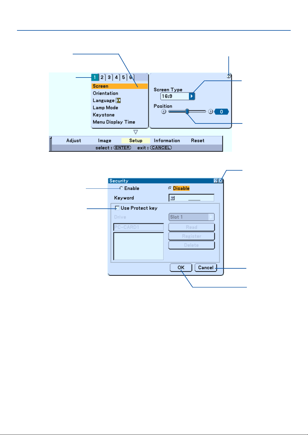
77
Menu Elements
Slide bar
Solid triangle
Highlight
Tab
Radio button
Check box
Cancel button
OK button
Menu windows or dialog boxes typically have the following elements:
Highlight................ Indicates the selected menu or item.
Solid triangle ......... Indicates further choices are available. A highlighted triangle indicates the item is active.
Tab ........................ Indicates a group of features in a dialog box. Selecting on any tab brings its page to the front.
Radio button ......... Use this round button to select an option in a dialog box.
Check box ............. Place a checkmark in the square box to turn the option On.
Slide bar ................ Indicates settings or the direction of adjustment.
OK button .............. Press to confirm your setting. You will return to the previous menu.
Cancel button ........ Press to cancel your setting. You will return to the previous menu.
Close button .......... Click to close the window with saving changes. (USB mouse only)
Help button ........... Indicates that help about that feature is available (USB mouse only). Press the HELP button on the remote
control to display help.
Help button
Close button
7. Using On-Screen Menu
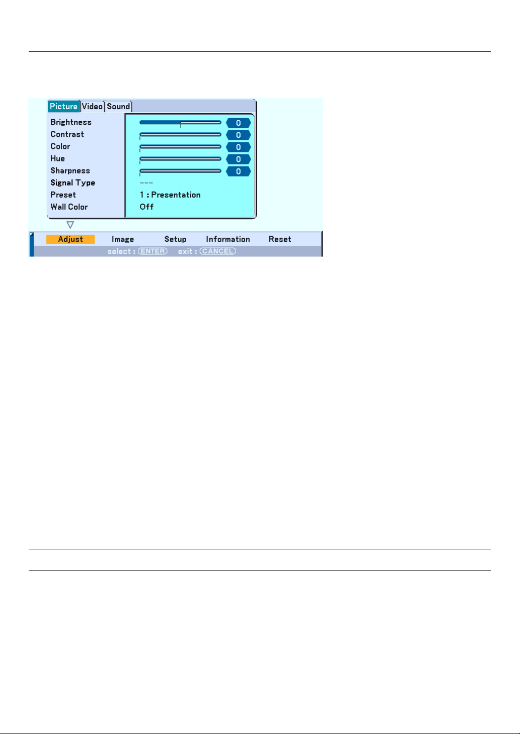
78
Menu Descriptions & Functions [Adjust]
Picture
[Brightness]
Adjusts the brightness level or the back raster intensity.
[Contrast]
Adjusts the intensity of the image according to the incoming signal.
You have two options: Manual/Auto.
[Color]
Increases or decreases the color saturation level (not valid for RGB).
[Hue]
Varies the color level from +/- green to +/-blue. The red level is used as reference. This adjustment is only valid for
Video, Component and TV standard inputs (not valid for RGB).
[Sharpness]
Controls the detail of the image for Video (Not valid for RGB).
Selecting Signal Type [Signal Type]
Select either the computer signal type or the component signal type.
RGB ....................... Computer signal
Component............ Component signals such as Y/Cb/Cr, Y/Pb/Pr
NOTE: This feature is available on the computer signal only. If you do not get a better picture even when you set "Signal Select" to
"Component" in Setup, set this to "Component".
7. Using On-Screen Menu

79
[Preset]
This option allows you to adjust neutral tint for yellow, cyan or magenta. There are 5 factory presets optimized for
various types of images, you can set user adjustable settings.
Detail Settings
This will provide you with three pages of menus that provide more detailed settings.
[Page1]
Selecting Reference Setting [Reference]
This feature allows you to use color correction or gamma values as reference data to optimize for various types of
images. You can select one of the following five settings.
Presentation ...... Recommended for presentations from a computer.
Video ................. Recommended for standard video such as a TV program.
Movie ................ Recommended for film based video such as a movie (DVD or HDTV).
Graphic .............. Recommended for viewing accurate colors in graphics.
sRGB ................. Standard color values.
Selecting Gamma Correction Mode [Gamma Correction]
Each mode is recommended for:
Dynamic ............ Creates a high-contrast picture.
Natural ............... Natural reproduction of the picture.
Black Detail ........ Emphasizes detail in dark areas of the picture.
Adjusting Color Temperature [Color Temperature]
This feature adjusts the color temperature using the slide bar. The range is between 5000K and 9300K.
NOTE:
* When "Presentation" is selected in "Reference", this function is not available.
* When "White Balance" settings has been changed, the color temperature value on screen does not reflect the real color
temperature.
[Page 2]
Adjusting White Balance [White Balance]
This allows you to adjust the white balance. Brightness for each color (RGB) is used to adjust the black level of the
screen; Contrast for each color (RGB) to adjust the white level of the screen.
[Page 3]
Selecting Color Correction [Color Correction]
Adjusts red, green, blue, yellow, magenta and cyan each independently to correct the tint on whole screen.
7. Using On-Screen Menu
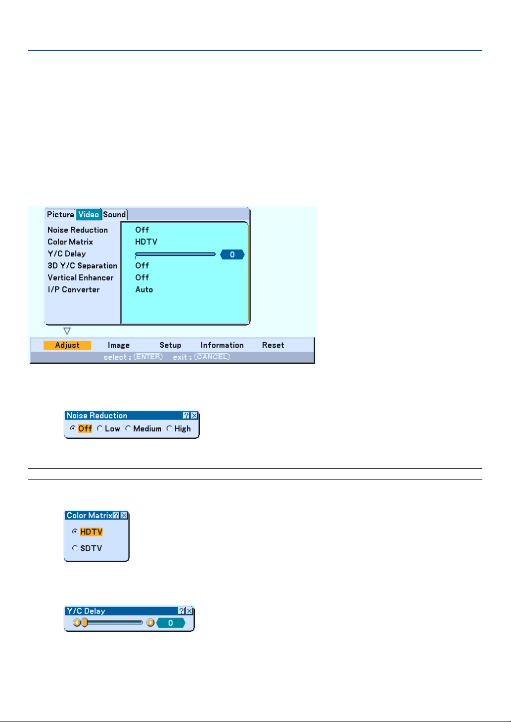
80
Using the Wall Color Correction [Wall Color]
[Interface to be determined]
This function allows for quick adaptive color correction in applications where the screen material is not white.
The following eight options are available.
• OFF • Blackboard
• Light yellow • Light green
• Light blue • Sky blue
• Light rose • Pink
Video Adjustment
Selecting Noise Reduction Level [Noise Reduction]
(not available for COMPUTER1/2 and Viewer; available for TV standard inputs)
Select one of the three levels for reducing video noise: Low, Medium or High.
NOTE: The lower the Noise Reduction level, the better the image quality by way of higher video bandwidth.
Selecting Color Matrix [Color Matrix]
Select an appropriate color matrix for your input signal, either HDTV or SDTV.
Adjusting Y/C Delay Level [Y/C Delay]
Adjusts Y/C delay level.
7. Using On-Screen Menu
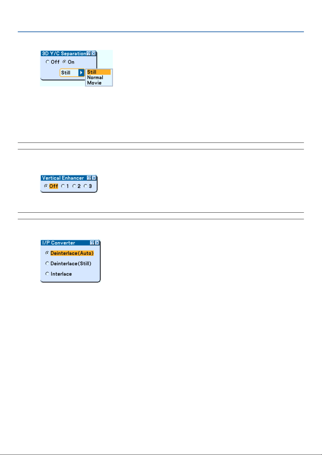
81
Turning On/Off 3 Dimension Separation [3D Y/C Separation]
This function turns on or off the 3 dimensional separation feature.
When "On" is selected, the following three options are available from the pull-down list.
Still ........................ Select this option for a still image.
Normal .................. The projector automatically makes the appropriate settings for a detected source.
Movie .................... Select this option for a moving image.
NOTE: This feature is available for NTSC3.58 of Video signal only.
Setting Vertical Edges [Vertical Enhancer]
This function enhances the vertical edges around objects in the image.
NOTE: This function is not available for an RGB and Component signal.
Selecting Interlace or Deinterlace [I/P Converter]
This function allows you to select between "Interlace" and "Deinterlace".
Deinterlace (Auto) ....... The projector automatically determines a still or moving image to display a clear picture. If selecting
"Deinterlace (Auto)" causes excess jitter or artifacts, select "Interlace".
Deinterlace (Still) ......... Select when a still image is displayed. When this option is selected for a moving image, jitter or artifacts
can be seen.
Interlace ...................... Select when a moving image is displayed. This will eliminate jitter and artifacts in a moving image.
7. Using On-Screen Menu
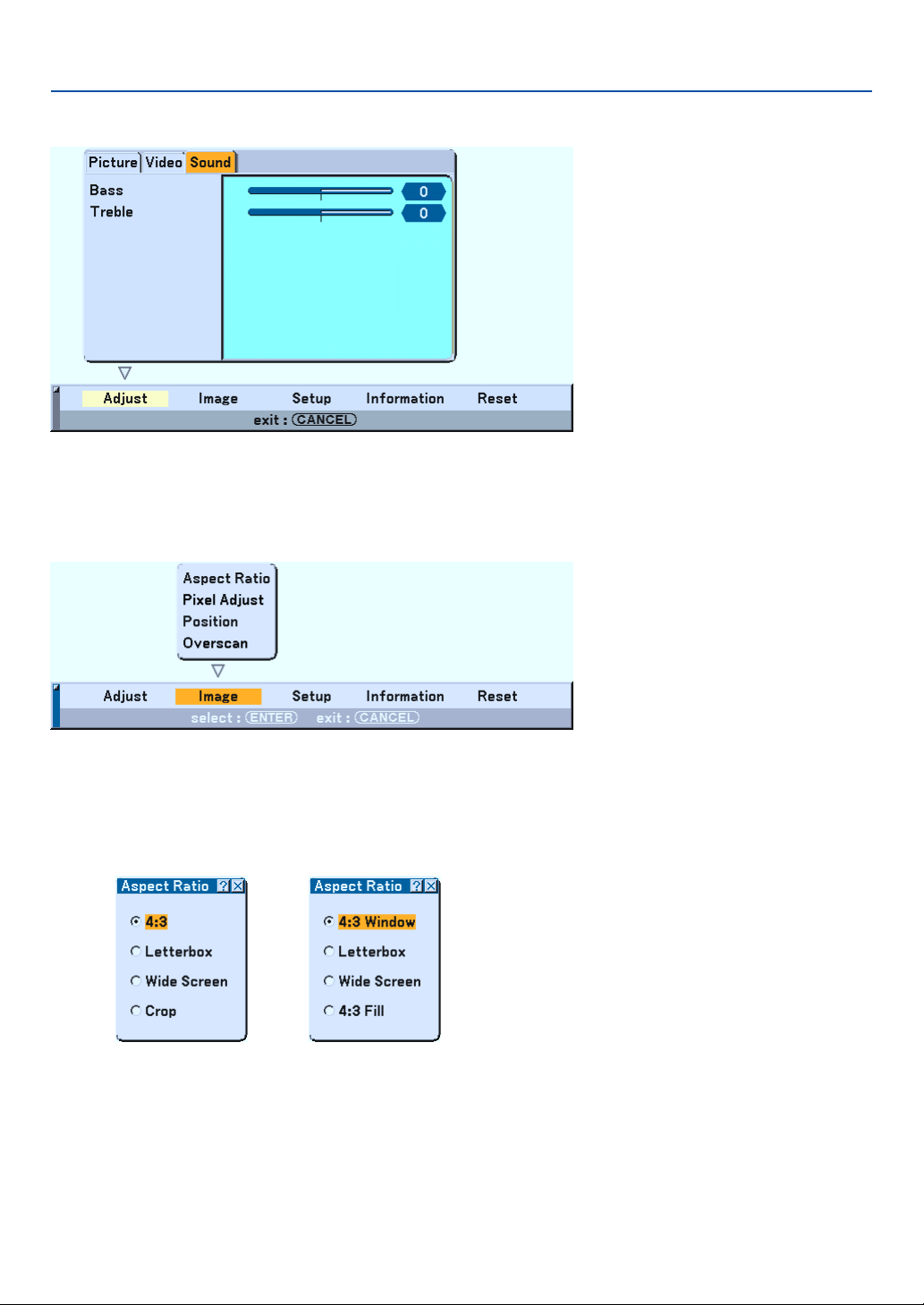
82
Controlling Bass and Treble [Sound]
You can adjust the bass and treble level of the projector speakers and AUDIO OUT (Stereo Mini Jack).
Menu Descriptions & Functions [Image]
[Page 1]
Selecting Aspect Ratio [Aspect Ratio] (not available for Viewer)
Screen Type 4:3 Screen Type 16:9
Aspect Ratio allows you to select the best Aspect mode to display your source image.
When screen type 4:3 is selected for the source, the following selections will display:
4:3 ......................... Standard 4:3 aspect
Letter Box .............. Reduced to display the true aspect with black borders on top and bottom
Wide Screen .......... Left & Right stretched with black borders on top and bottom
Crop ...................... Left & Right stretched. Left & Right sides cut. Available for 4:3 only.
7. Using On-Screen Menu
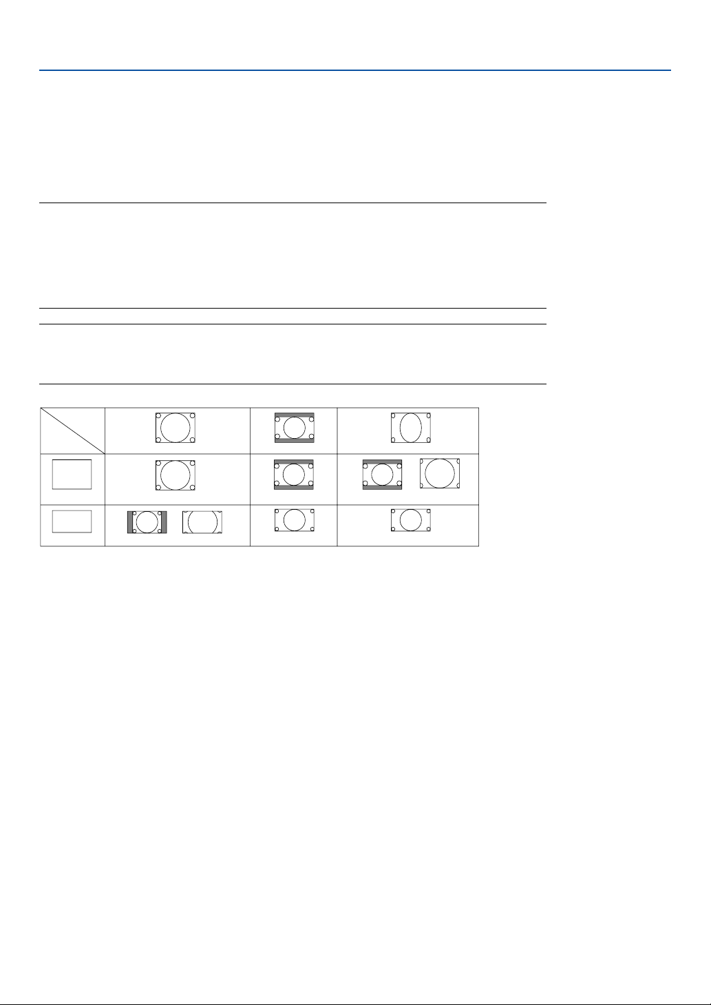
83
When screen type 16:9 is selected for the source, the following selections will display:
4:3 Window ........... Reduced to display the true aspect with black borders on right and left
Letter Box .............. Standard 16:9 aspect
Wide Screen .......... Left and right stretched to display the true aspect
4:3 Fill ................... Stretched to display in 16:9 aspect ratio
NOTE: You can adjust image positions vertically for source with black borders. See page 85 for setting
image positions.
Copyright
Please note that using this projector for the purpose of commercial gain or the attraction of public
attention in a venue such as a coffee shop or hotel and employing compression or expansion of the
screen image with a "Aspect Ratio" or "Screen" setting may raise concern about the infringement of
copyrights which are protected by copyright law.
NOTE: During 3D Reform adjustment, "Aspect Ratio" may not be available.
Should this happen, first reset the 3D Reform data and then do setting again. Second repeat the 3D
Reform adjustment.
Changing the aspect ratio can limit 3D Reform in its adjustable range.
Input
Signal
Screen
Type
4:3 Screen
16:9 Screen
4:3
4:3 Window
4:3 Fill
Squeeze
Wide Screen
Wide Screen
Crop
Letterbox
4:3 Letterbox
Letterbox
7. Using On-Screen Menu
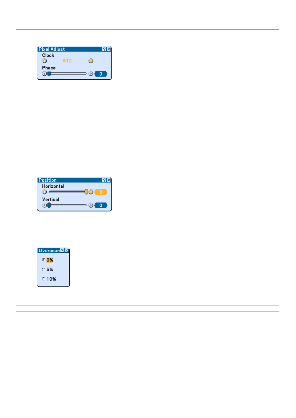
84
Adjusting Clock and Phase [Pixel Adjust]
This allows you to manually adjust Clock and Phase.
Clock
Use this item to fine tune the computer image or to remove any vertical banding that might appear. This function
adjusts the clock frequencies that eliminate the horizontal banding in the image.
This adjustment may be necessary when you connect your computer for the first time.
Phase
Use this item to adjust the clock phase or to reduce video noise, dot interference or cross talk. (This is evident
when part of your image appears to be shimmering.)
Use "Phase" only after the "Clock" is complete.
Adjusting Horizontal/Vertical Position [Position]
Adjusts the image location horizontally and vertically.
Selecting Overscan Percentage [Overscan]
Select overscan percentage (0%, 5% and 10%) for signal.
NOTE: When "4:3 Fill" or "Crop" is selected in "Aspect Ratio", this feature is not available.
7. Using On-Screen Menu
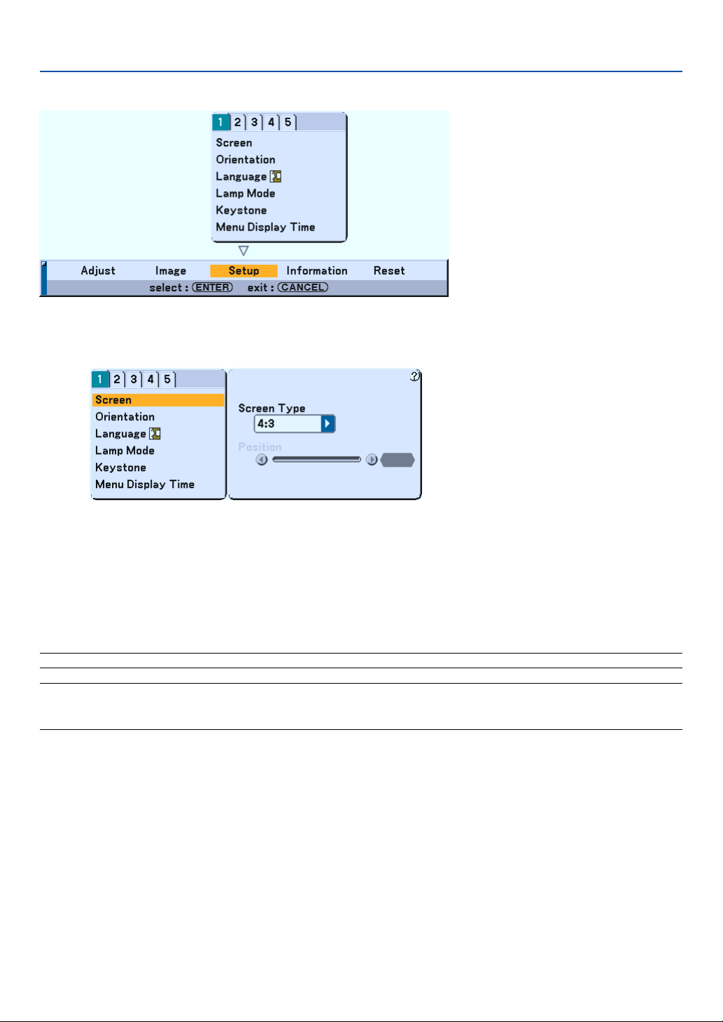
85
Menu Descriptions & Functions [Setup]
Setup [Page1]
Selecting Aspect Ratio and Position for Screen [Screen]
Screen Type
Select one of three options: 4:3 Screen or 16:9 Screen for the screen to be used. See also "Aspect Ratio" on
pages 82 and 83.
Position
This feature adjusts the vertical position of the image when viewing video with an aspect ratio selected.
When some aspect ratios are selected in Image, the image is displayed with black borders on the top and bottom.
You can adjust the vertical position between top and bottom.
NOTE: This option is available only when "16:9" is selected in Screen Type.
NOTE: During 3D Reform adjustment, "Screen Type" and "Screen Position" may not be available. To make available, first reset the
3D Reform data and then do settings again. Secondly repeat the 3D Reform adjustment. Changing "Screen Type" and "Screen
Position" can limit 3D Reform in its adjustable range.
7. Using On-Screen Menu
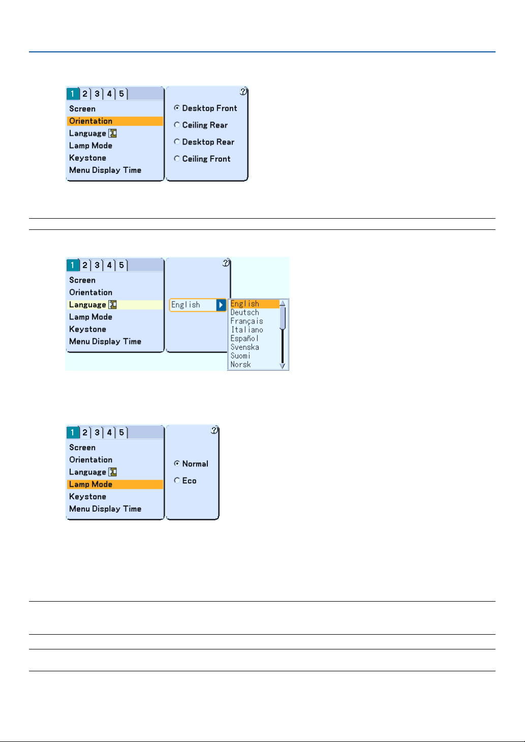
86
Selecting Projector Orientation [Orientation]
This reorients your image for your type of projection. The options are: desktop front projection, ceiling rear projection,
desktop rear projection, and ceiling front projection.
NOTE: Selecting one of the other options than “Desktop Front” will force the “Keystone” mode to be “Manual".
Selecting Menu Language [Language]
You can choose one of 19 languages for on-screen instructions.
Setting Lamp Mode to Normal or Eco [Lamp Mode]
This feature enables you to select two brightness modes of the lamp: Normal and Eco modes. The lamp life can be
extended up to 3000 hours by using the Eco mode. Selecting Eco mode decreases fan noise compared to in Normal
mode.
Normal Mode ........ This is the default setting (100% Brightness).
Eco Mode .............. Select this mode to increase the lamp life (76% Brightness).
NOTE: If the projector is overheated in Normal mode, there may be a case where the Lamp mode automatically changes to Eco
mode to protect the projector. When the projector is in Eco mode, the picture becomes slightly darker. When the projector comes
back to normal temperature, the Lamp mode returns to Normal mode.
NOTE: When a picture is muted or there are no signals (blue or black screen), the Eco mode will be automatically selected in
"Lamp Mode."
7. Using On-Screen Menu
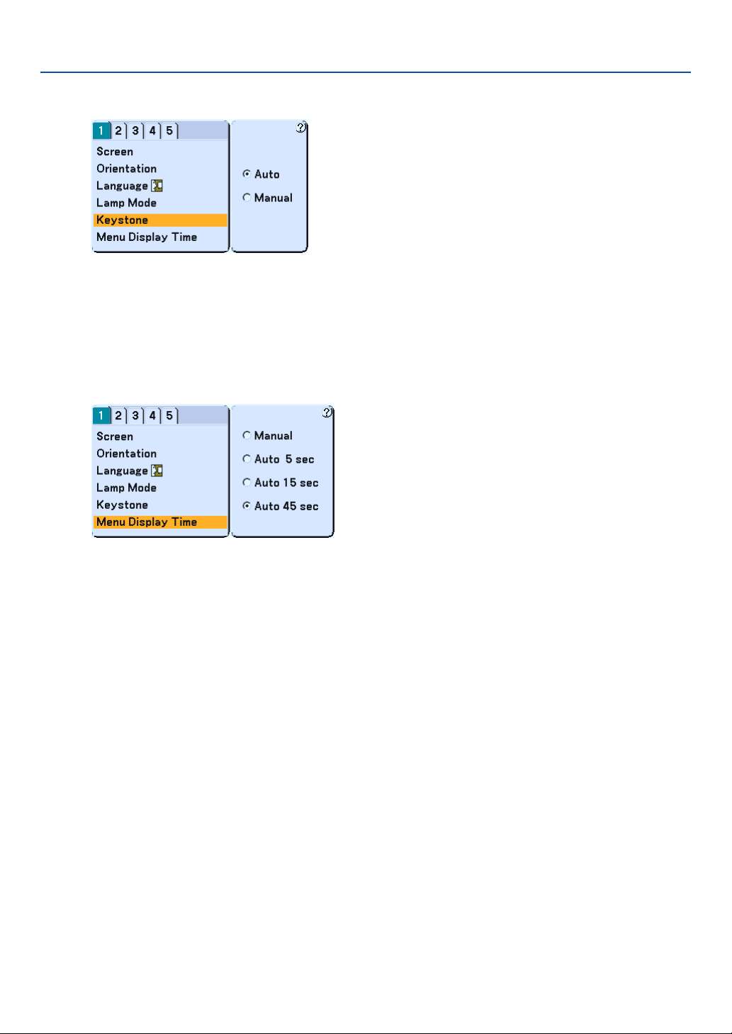
87
Selecting Keystone Mode [Keystone]
This feature allows you to correct keystone distortion manually or automatically.
Auto ...................... This feature allows the projector to detect its tilt and correct vertical distortion automatically.
Manual .................. You can correct vertical distortion manually from the menu.
Changes will be saved even when you turn off the projector.
Selecting Menu Display Time [Menu Display Time]
This option allows you to select how long the projector waits after the last touch of a button to turn off the menu. The
preset choices are "Manual", "Auto 5 sec", "Auto 15 sec", and "Auto 45 sec". The "Auto 45 sec" is the factory preset.
Manual .................. The menu can be turned off manually.
Auto 5 sec ............. The menu will automatically be turned off in 5 seconds if no buttons are pressed within 5 seconds.
Auto 15 sec ........... The menu will automatically be turned off in 15 seconds if no buttons are pressed within 15 seconds.
Auto 45 sec ........... The menu will automatically be turned off in 45 seconds if no buttons are pressed within 45 seconds.
7. Using On-Screen Menu
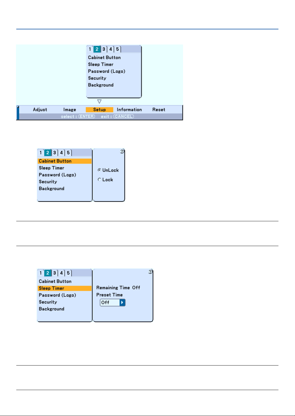
88
Setup [Page2]
Disabling the Cabinet Buttons [Cabinet Button]
This option turns on or off the Cabinet Button Lock function.
NOTE:
• This Cabinet Button Lock does not affect the remote control functions.
• When the cabinet buttons are locked, pressing and holding the CANCEL button for about 10 seconds will change the setting to
unlock.
Using Sleep Timer [Sleep Timer]
1. Select your desired time between 30 minutes and 16 hours: Off, 0:30, 1:00, 2:00, 4:00, 8:00, 12:00, 16:00.
2. Press the ENTER button on the remote control.
3. The remaining time starts counting down.
4. The projector will turn off after the countdown is complete.
NOTE:
•To cancel the preset time, set "Off" for the preset time or turn off the power.
• When the remaining time reaches 3 minutes before the projector is turned off, the "Projector will turn off in 3 minutes"
message will be displayed on the bottom of the screen.
7. Using On-Screen Menu
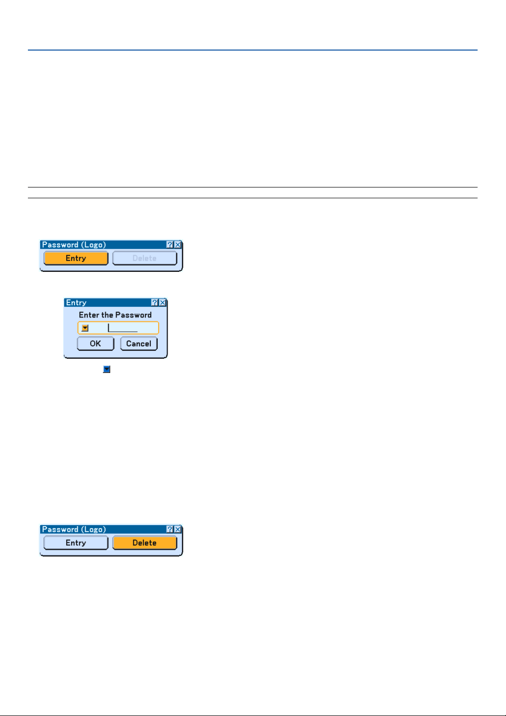
89
Setting a Password [Password (Logo)]
A password can be set for your projector to avoid operation by an unauthorized person.
When a password is set, doing any one of the following two operations will display the Password input screen.
• Changing the background
• Changing the logo data in a PC card
Entry:
To assign your password:
NOTE: Up to 15 alphanumeric characters can be assigned.
1. Type a password.
Highlight "Entry" and press the ENTER button.
The "Enter the Password" screen will be displayed.
Make sure that is highlighted and then press the ENTER button.
The Software keyboard appears. Use the Software keyboard to type a password and then highlight "OK"
on the “Enter the Password” screen and press the ENTER button.
The [Confirm Password] screen will be displayed.
2. Type the same password again. Highlight "OK" on the “Enter the Password” screen and press the
ENTER button.
Your password will be assigned.
Delete:
To delete your password:
1. Highlight [Delete] and press the ENTER button. The "Current Password" screen will be displayed.
2. Use the Software keyboard to type your password. Highlight "OK" on the “Current Password” screen and
then press the ENTER button.
Your password will be deleted.
7. Using On-Screen Menu
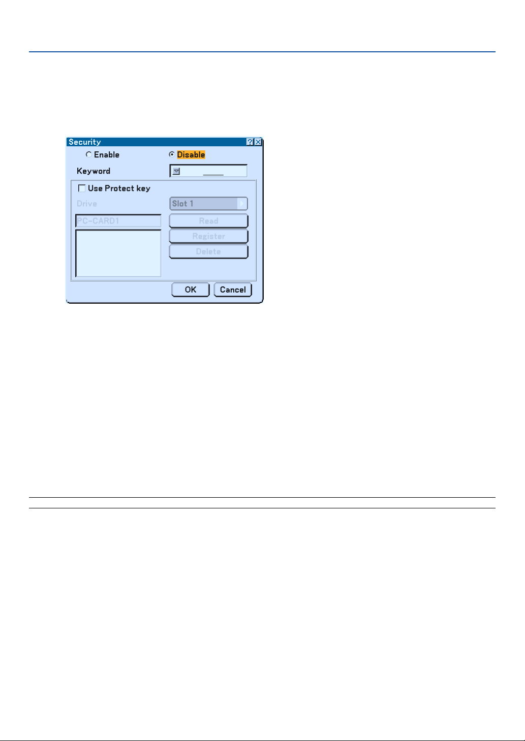
90
Security
The Security function enables you to protect your projector so that the projector will not project a signal unless you
enter a keyword. There is also an option to lock the projector by using a registered PC card as a protect key. Once you
have registered your PC card as a protect key, you are required to insert the registered PC card into the PC card slot
of the projector each time you turn on the projector. You can enable the Security function by using a keyword only.
Enable/Disable ....... This turns the Security function on or off.
Keyword ................ Enter an appropriate keyword when you use the Security function. (Up to 10 characters can be used.) The
Security function is available only when your keyword is entered.
Use Protect key ..... Check this box to lock your projector when using a PC card. To use a keyword without a PC card, do not
check this box.
Drive...................... Switches between PC Card slot and USB port (type A).
Read ...................... Reads data from a PC card.
Register ................. Registers data from the PC card. The Security function is not available unless at least one PC card is
registered. (if the “Use Protect key” check box is selected) Up to 5 PC cards can be registered.
Delete .................... Deletes data of a registered PC card.
To set up a keyword to enable the Security function without using a registered PC card.
1. Use the SELECT
왖왔
button to select “Keyword” and use the software keyboard to enter a keyword.
NOTE: Please make a note of your keyword.
2. Use the SELECT
왖왔
button to select “Enable” and use the SELECT
왖왔
button to select “OK”, then the
Security function will be enabled.
An “Are you sure?” message will appear. Use the SELECT
왗왘
button to select “OK” and press the
ENTER button.
The Security function takes effect.
7. Using On-Screen Menu

91
To register a PC card as a protect key.
1. Insert a PC card into the PC card slot of the projector.
2. Use the SELECT
왖왔
button to select "Use Protect Key" and press the ENTER button.
3. Use the SELECT
왖왔
button to select "Read" and press the ENTER button.
Data of the PC card will be read into the projector.
4. Use the SELECT
왖왔
button to select "Register" and press the ENTER button.
Downloaded data will be registered and be displayed in the list window.
5. Use the SELECT
왖왔
button to select "Keyword" and use the software keyboard to enter a keyword.
NOTE: To use a PC card as a protect key, you must also set up a keyword. Please make a note of your keyword.
This completes registration of your PC card.
To enable Security, use the SELECT 왖왔 button to select "Enable" and use the SELECT 왖왔 button to select "OK" and
"Security function will be enabled. An “Are you sure?" message will appear. Use the SELECT 왗왘 button and press the
ENTER button.
The Security function takes effect.
To turn on the projector when Security is enabled (when using your keyword only).
1. Press and hold the POWER button for a minimum of two seconds.
The projector will be turned on and display a message to the effect that the projector is security-pro-
tected.
2. Select [Setup]
→
[Page 2]
→
[Security] from the menu and press the ENTER button.
The Release Code input screen will be displayed.
3. Enter your keyword in the Release Code input screen.
You can view the projected image.
NOTE: Do not forget your keyword. However, if you forget your keyword, NEC or your dealer will provide you with your Release
Code. See more information at the end of this section.
To turn on the projector when Security is enabled (when using PC card as a protect key).
1. Insert your registered PC card into the PC card slot.
2. Press and hold the POWER button for a minimum of two seconds.
The projector will turn on and then recognize the PC card. Once the image has been projected, it will
stay on without the PC card.
• The security disable mode is maintained until the main power is turned off (by setting the main power switch
to "O" or unplugging the power cord). In the following cases you will be asked to check the protect key or input
the keyword:
(1)When "OK" is selected at an image for which security is set and the power is turned off then back on
(2)When the main power is turned off then back on while the security function is enabled
(3)When you attempt to display an image for which security is set while the security function is enabled
• Blanks (spaces) cannot be used in the Keyword section.
7. Using On-Screen Menu
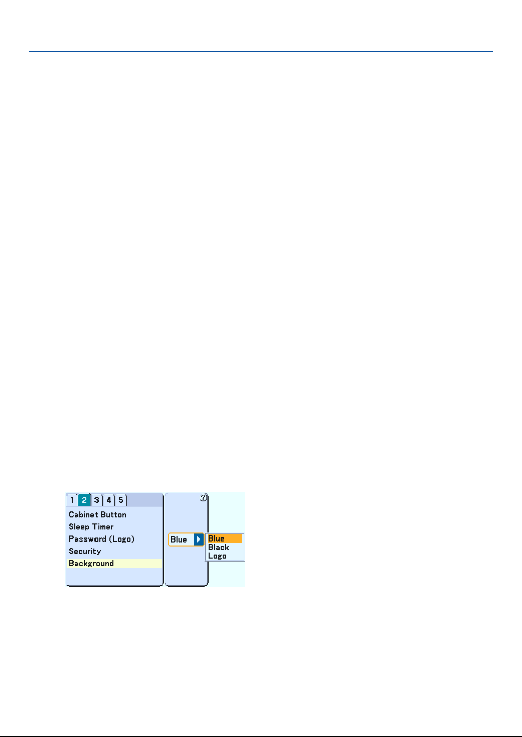
92
To delete PC card data you registered.
1. Use the SELECT
왖왔
button to select "Delete" and use the SELECT
왗
button to select the list window.
2. Use the SELECT
왖왔
button to select the PC card data you wish to delete.
3. Press the SELECT
왘
button to select "Delete" and press the ENTER button.
The PC card data will be deleted.
If you've lost your registered PC card, proceed as follows:
NOTE: NEC or your dealer will provide you with your Release Code in exchange for your registered keyword and Request Code.
See more information at the end of this section.
1. Press and hold the POWER button for a minimum of two seconds.
The projector will be turned on and display a message to the effect that the projector is security-pro-
tected.
2. Select [Setup]
→
[Page 2]
→
[Security] from the menu and press the ENTER button.
The Release Code input screen will be displayed as well as your Request Code (24 alphanumeric
characters).
3. Enter your Release Code in the Release Code Input screen.
The projector will turn on.
* If the projector is turned on by entering the Release Code, your Security will be disabled.
NOTE:
• Some types of PC cards cannot be registered as your protect key.
• It is recommended that you register two or more PC cards in case you lose or damage your registered PC card.
• Formatting your registered PC card will disable your protect key function.
NOTE:
For additional information visit:
US : http://www.necvisualsystems.com
Europe : http://www.nec-europe.com/
Global : http://www.nec-pj.com/
Selecting a Color or Logo for Background [Background]
Use this feature to display a blue/black screen or logo when no signal is available. The default background is blue. You
can change the logo screen using the Viewer feature. See pages 64.
NOTE: When the projector displays a blue or a black screen, the Eco mode will be automatically selected in "Lamp Mode."
7. Using On-Screen Menu
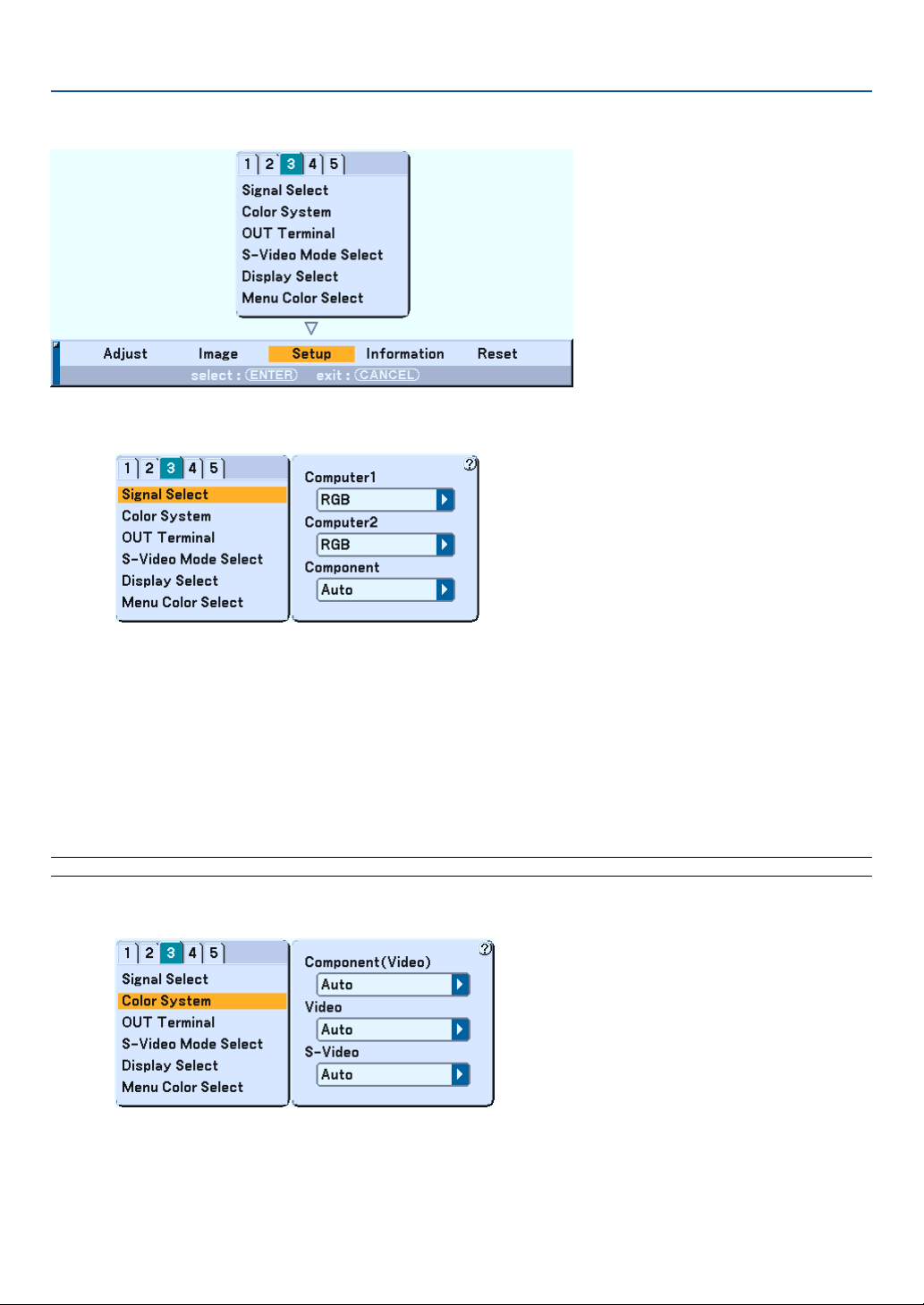
93
Setup [Page3]
Selecting Signal Format [Signal Select]
Computer 1/2
Allows you to set "Computer 1" and "Computer 2" to automatically detect an incoming RGB or component source
such as a computer or DVD player. However there may be some RGB and component signals that the projector is
unable to detect. In this case, select "RGB" or "Component".
Select "Scart" in COMPUTER 2 for the European Scart signal.
Component
Normally select "Auto" and the projector automatically detects an incoming signal. However there may be some
component signals that the projector is unable to detect.
If this is the case, select "Component".
NOTE: When using the "Y" connector of the COMPONENT connectors to display a Video signal, select "Video".
Selecting Color System [Color System]
This feature enables you to select composite video standards automatically or manually.
Normally select "Auto" and the projector will automatically detect the video standard.
In the case where the projector has difficulty detecting the video standard, select the appropriate video standard from
the menu.
7. Using On-Screen Menu
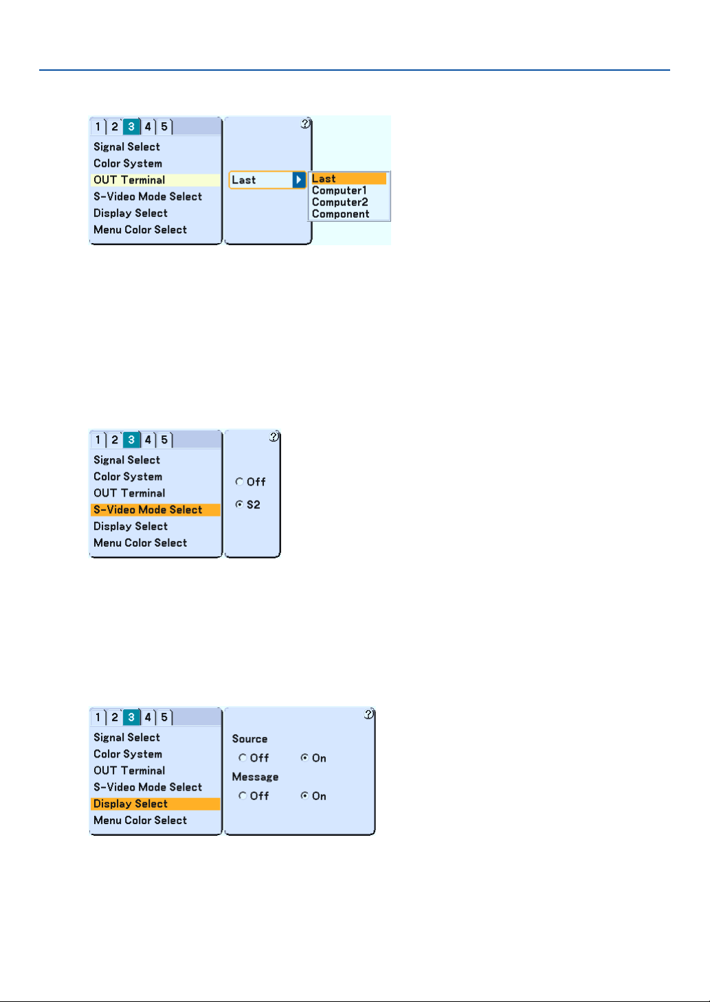
94
Setting MONITOR OUT Connector [OUT Terminal]
This option allows you to determine which RGB or component source is output from the MONITOR OUT connector
during Idle mode.
Last ....................... The signal from the last COMPUTER1 or 2, or COMPONENT input will be output to the MONITOR OUT
connector.
COMPUTER 1, 2 .... The signal from the COMPUTER1 or 2 input will be output to the MONITOR OUT connector.
COMPONENT ........ The signal from the COMPONENT input will be output to the MONITOR OUT connector.
Selecting S-Video Mode [S-Video Mode Select]
This feature is used to select the S-Video signal detection mode. This allows identifying of the S-Video signals with
different aspect ratio (16:9 and 4:3).
Off ......................... Does not identify any S-video signal.
S2.......................... Identifies the 16:9 or 4:3 signal.
Turning On / Off Source Display and Message [Display Select]
Source
This option turns on or off input name display such as Computer 1/2, Video, and No Input to be displayed in the top
right corner of the screen.
Message
This option turns on and off messages for lamp life warning, 3-minute before power off time, “Please clean filter”
and “Please wait a moment”.
7. Using On-Screen Menu
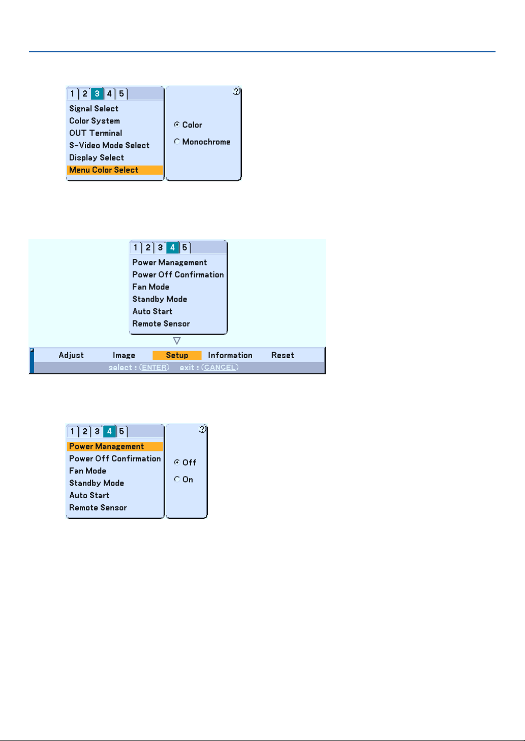
95
Selecting Menu Color [Menu Color Select]
You can choose between two color modes for menu color: color and monochrome.
Setup [Page4]
Enabling Power Management [Power Management]
When this option is on and there is no input for five minutes or more, the projector will automatically turn itself off.
7. Using On-Screen Menu
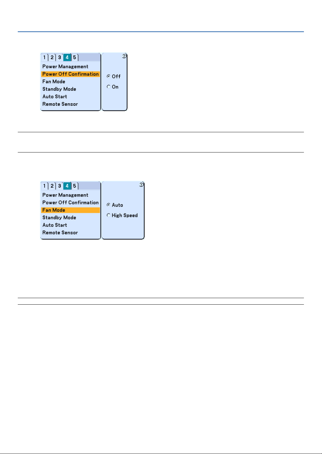
96
Enabling Power Off Confirmation [Power Off Confirmation]
This option determines whether a confirmation dialog for turning off the projector will appear or not.
NOTE: When the confirmation message is displayed, you must be in the Projector mode to operate your projector using the
remote control. If not, press the PJ button on the remote control to change your projector to the Projector mode. The button
lights to indicate that you are in the Projector mode.
Enabling High Speed Fan Mode [Fan Mode]
This option allows you to select two modes for fan speed: Auto mode and High speed mode.
Auto ...................... The built-in fans automatically run at a variable speed according to the internal temperature.
High Speed ............ The built-in fans run at a fixed high speed.
When you wish to cool down the temperature inside the projector quickly, select “High Speed”.
NOTE: Select High speed mode if you continue to use the projector for consecutive days.
7. Using On-Screen Menu
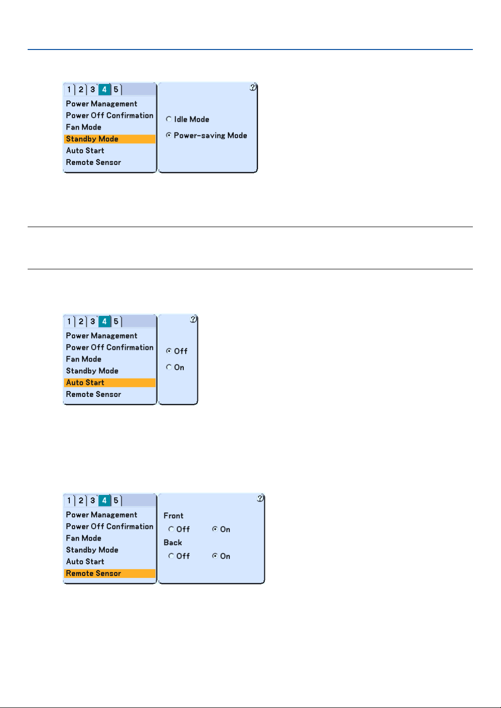
97
Enabling Standby Mode [Standby Mode]
The projector has two standby modes: Idle mode and Power-saving mode.
Power-saving mode is the mode that allows you to put the projector in the standby condition which consumes less
power than the Idle mode. The projector is preset for Idle mode at the factory.
NOTE:
• The MONITOR OUT function is not available during Power-saving mode.
• Control through the PC Control connector is not available during Power-saving mode. For PC control of the projector it is
recommended to leave the projector in Idle mode.
Enabling Auto Start [Auto Start]
Tu r ns the projector on automatically when the power cable is inserted into an active power outlet and the main power
switch is turned on. This eliminates the need to always use the "Power" button on the remote control or projector
cabinet.
[Remote Sensor]
This option determines which remote sensor on the projector is enabled.
Selecting “On” indicates that the selected remote sensor can accept the infrared signal from the supplied remote
control.
7. Using On-Screen Menu
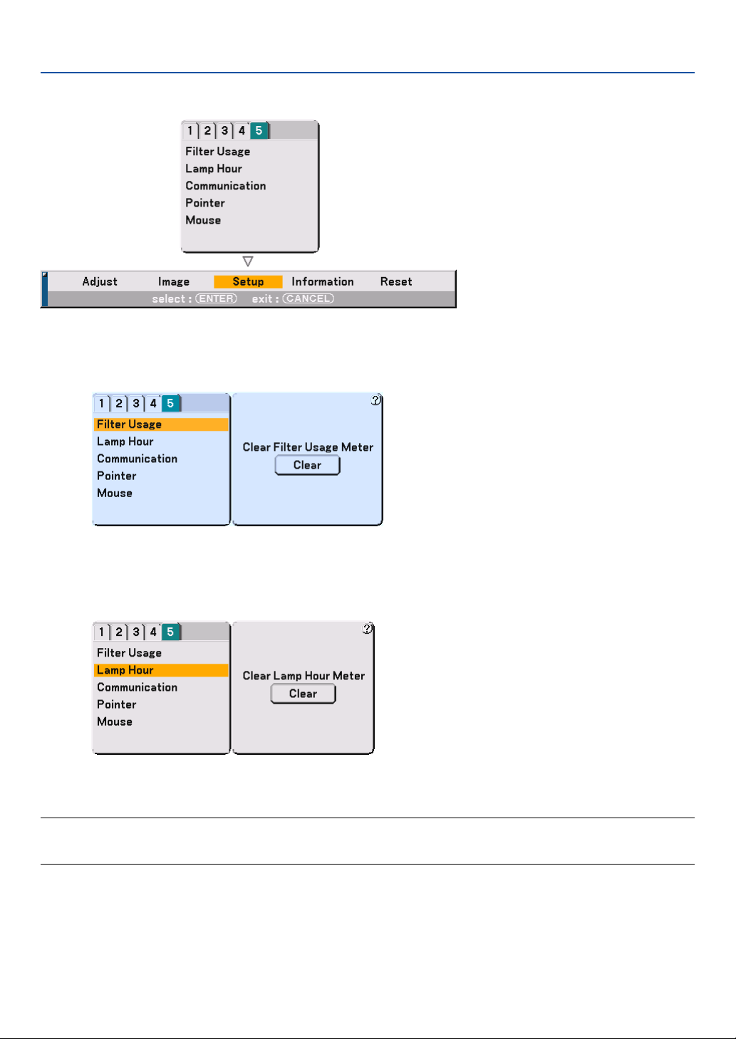
98
Setup [Page5]
Resetting the Filter Usage Hours [Filter Usage]
Resets the filter usage back to zero. Pressing the Clear button displays a confirmation dialog box. To reset the filter
usage hours, press "OK".
Clearing Lamp Hour Meter [Lamp Hour]
Resets the lamp clock back to zero. Pressing the Clear button displays a confirmation dialog box. To reset the lamp
usage hour, press "OK".
NOTE: The projector will turn off and go into standby mode after 2100 hours (up to 3100 hours in Eco mode) of service. In this
condition you cannot clear the lamp hour meter on the menu. If this happens, press the "HELP" button on the remote control for
ten seconds to reset the lamp clock back to zero. Do this only after replacing the lamp.
7. Using On-Screen Menu
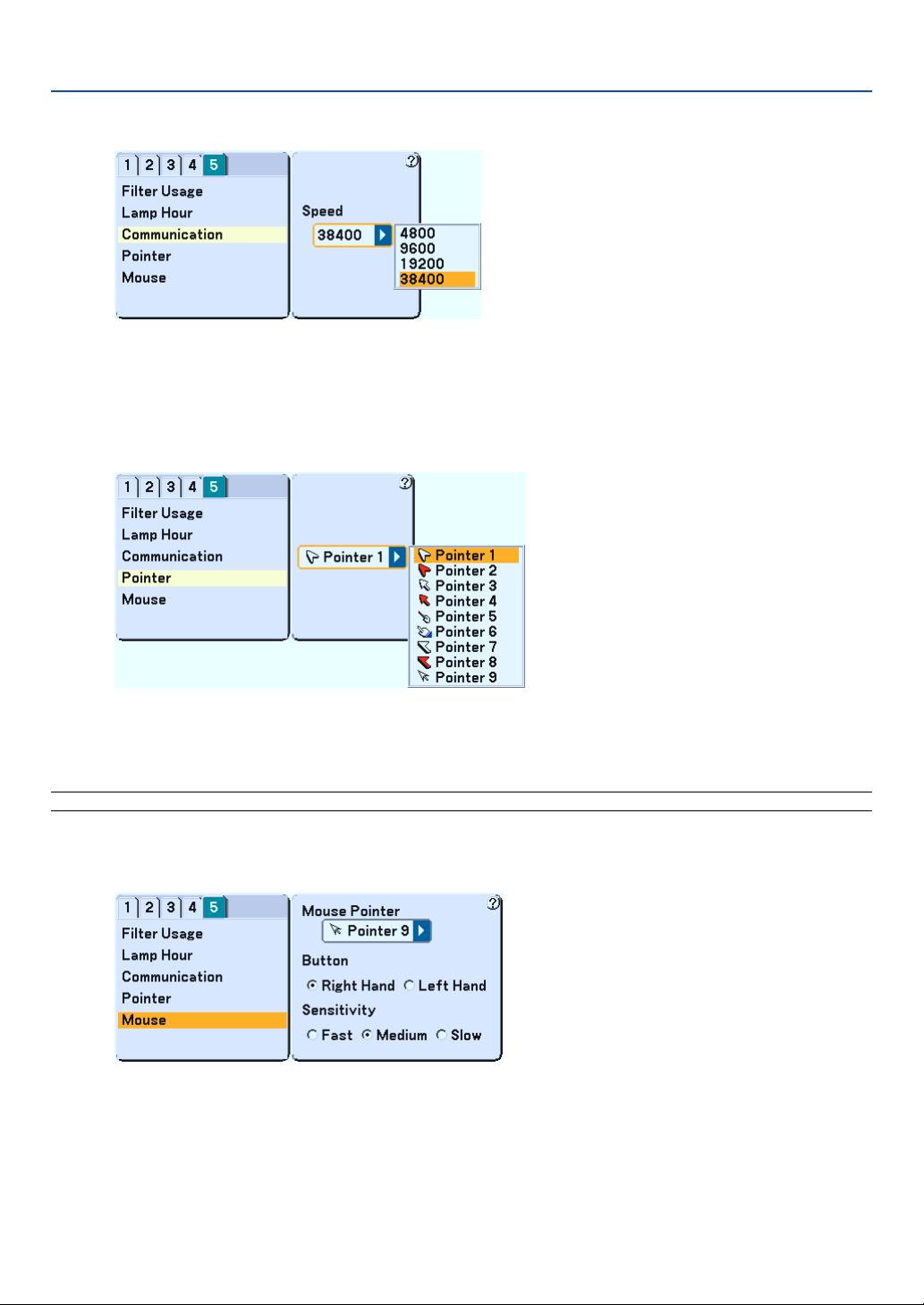
99
Selecting Communication Speed [Communication]
This feature sets the baud rate of the PC Control port (D-Sub 9 Pin). It supports data rates from 4800 to 38400 bps.
The default is 38400 bps. Select the appropriate baud rate for your equipment to be connected (depending on the
equipment, a lower baud rate may be recommended for long cable runs).
Selecting Projecting Pointer Icon [Pointer]
This enables you to select from nine different Pointer icons for the "Pointer" button on your remote control.
After moving your Pointer icon to the area you want on the screen, press the MAGNIFY button on the remote control
to enlarge the selected area on the screen. See page 41 for more details.
NOTE: There may be cases where the Pointer function is not available (ex. A non-interlace signal at 15kHz such as video game.)
Setting Mouse Pointer, Button and Sensitivity [Mouse]
This option lets you to change your USB mouse settings. The mouse settings feature is available for USB mouse only.
Choose the settings you want:
Mouse Pointer ....... Pointer 1 - 9
Mouse Button ........ "Right Hand" or "Left Hand"
Mouse Sensitivity .. "Fast", "Medium" or "Slow"
7. Using On-Screen Menu
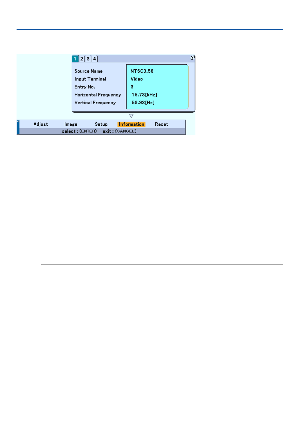
100
Menu Descriptions & Functions [Information]
Displays the status of the current signal, the lamp and the projector usage hours. This dialog box has four pages.
The information included are as follows:
[Page 1] Source Name
Input Terminal
Entry No.
Horizontal Frequency
Ver tical Frequency
[Page 2] Signal Type
Video Type
Sync Type
Interlace
Sync Polarity
[Page 3] Remaining Lamp Time (%)
Lamp Hour Meter (H)
Filter Usage (H)
Projector Usage (H)
NOTE: The progress indicator shows the percentage of remaining bulb life. The value informs you of the amount of
lamp and projector usage respectively.
[Page 4] Version (BIOS, Firmware, Data)
Remaining Lamp Time Display
When the remaining lamp time reaches 0, the Remaining Lamp Time bar indicator changes from 0% to 100 Hours and
starts counting down. If the remaining lamp time reaches 0 hours, the projector will not turn on regardless of whether
the lamp mode is set to Normal or Eco.
7. Using On-Screen Menu

101
Menu Descriptions & Functions [Reset]
Returning to Factory Default
The Reset feature allows you to change adjustments and settings to the factory preset for sources by the following
methods:
Current Signal
Resets the adjustments for the current signal to the factory preset levels.
All the items in “Adjust (except “Wall Color”) and “Image" can be reset.
All Data
Reset all the adjustments and settings for all the signals to the factory preset except Remaining Lamp Time, Lamp
Hour Meter, Filter Usage, Projector Usage, Communication, Language, Background, Entry List, Standby Mode,
Security and Password (Logo).
(To reset the lamp usage time, see “Clear Lamp Hour Meter” on page 98)
All Data (Including Entry List)
Reset all the adjustments and settings for all the signals to the factory preset except Remaining Lamp Time, Lamp
Hour Meter, Filter Usage, Projector Usage, Communication, Language, Background, Entry List, Standby Mode,
Security and Password (Logo).
Also deletes all the signals in the Entry List and returns to the factory preset.
NOTE: Locked signals in Entry List cannot be reset.
7. Using On-Screen Menu
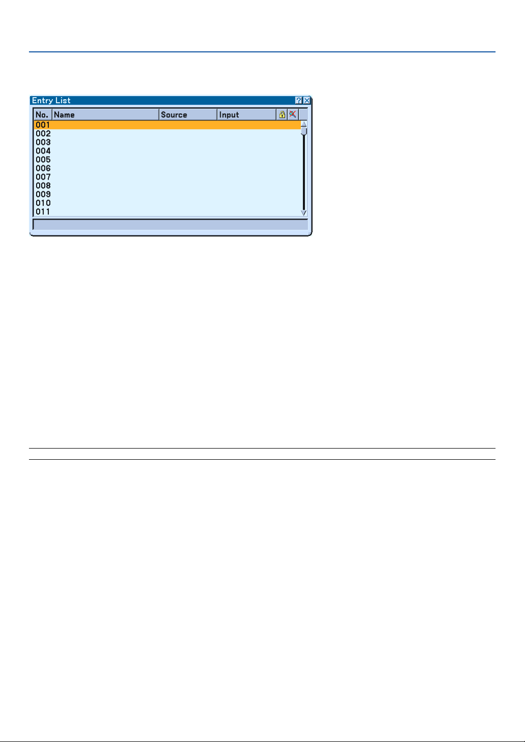
102
Entry List
Displaying the Entry List
Press the SOURCE button to display the list of the entry signals. Use the SELECT 왖왔 buttons on your remote control
or the projector cabinet to select the signal and press the ENTER button on the remote control or the projector cabinet
to display the Entry Edit Command screen.
Entering the Currently Projected Signal into the Entry List
1. Display the Entry List.
2. Use the SELECT
왖
or
왔
button on your remote control or the projector cabinet to select any number and
press the ENTER button on the remote control or the projector cabinet to display the Entry Edit Com-
mand screen.
3. Use the SELECT
왗
or
왘
button to select "Store" and press the ENTER button.
Using the Entry List
Making any adjustments to the current picture will automatically register its adjustments to the Entry List. The regis-
tered signal can be loaded any time from the Entry List.
NOTE: Up to 100 presets can be registered except settings on the Picture.
7. Using On-Screen Menu

103
7. Using On-Screen Menu
Entry Edit Command
You can edit signals on the Entry List.
Load ...................... Enables you to select a signal from the list.
Store ..................... Enables you to store the currently projected signal.
Cut ........................ Enables you to remove a selected signal from the list and place it on the "clipboard" in the projector.
Copy ...................... Enables you to copy a selected signal from the list and place it on the "clipboard" in the projector.
Paste ..................... Enables you to paste the signal placed on the "clipboard" to any other line of the list. To do this, select "Paste"
and then select the line number you want to paste to. Last press ENTER.
Edit ........................ Enables you to change source names.
Source Name:
Enter a signal name. Up to 18 alphanumeric characters can be used.
Input Terminal:
Change the input terminal. Video and S-Video are available for composite signal. Component and Computer
are available for component signal.
Lock:
Set so that the selected signal cannot be deleted when "All Delete" is executed.
Skip:
Set so that the selected signal will be skipped during auto search.
When complete, select OK and press ENTER. To exit without storing setting, select Cancel. Select "Source
Name" and press ENTER to display the Source Name Edit window. You can change source name on this
window. Press 왔 to display the software keyboard, which you can enter alphanumeric characters. See page
120 for the key function of the software keyboard.
All Delete ............... This feature enables you to delete all the registered signals in the Entry List.
The following buttons are not available for the currently projecting signals:
1) The Cut and Paste buttons on the Entry Edit Command screen
2) The Input Terminal button on the Entry Edit screen
NOTE: When all the signals in the Entry List are deleted, the currently projected signal will be also deleted except locked signals.

104
8
Maintenance
○○○○○○○○○○○○○○○○○○○○○○○○○○○○○○○○○○○○○○○○
Cleaning the Filters................................................. 105
Cleaning the Cabinet .............................................. 105
Cleaning the Lens................................................... 106
Replacing the Lamp and Filters .............................. 107
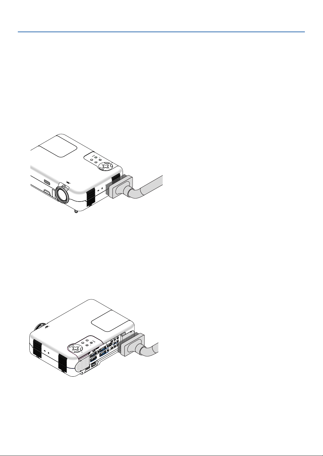
105
8. Maintenance
This section describes the simple maintenance procedures you should follow to clean the filter and replace the lamp.
Cleaning the Filters
The air-filter sponge keeps dust and dirt from getting inside the projector and should be cleaned after every 100 hours
of operation (more often in dusty conditions). If the filters are dirty or clogged, your projector may overheat.
CAUTION
•Turn off the projector, turn off the main power switch and unplug the projector before cleaning the filters.
• Only clean the outside of the filter cover with a vacuum cleaner.
1. Vacuum the filter from the outside.
2. Reset the filter usage time.
To reset the filter usage time, from the menu, select [Setup] → [Page 5] → [Filter Usage] → [Clear Filter Usage Meter]
and then press “Clear”.
See also page 98 for resetting the filter usage time.
Cleaning the Cabinet
CAUTION
Tu rn off the projector, turn off the main power switch and unplug the projector before cleaning the cabinet.
Clean the cabinet periodically with a damp cloth. If heavily soiled, use a mild detergent. Never use strong
detergents or solvents such as alcohol or thinner.
ZOOM
F
O
C
U
S
3D
R
EFO
R
M
SO
UR
C
E
SELEC
T
S
TA
TUS
LAM
P
PC
C
AR
D
P
OW
E
R
O
N/S
TAN
D B
Y
AU
TO
A
D
JU
S
T
M
E
N
U
E
N
T
E
R
C
A
N
C
E
L
A
C
IN
C
O
M
P
O
N
E
N
T
YC
b
/P
b
C
r/P
r
A
U
D
IO
A
U
D
IO
A
U
D
IO
S
-V
ID
E
O
C
O
M
P
U
T
E
R
1
A
U
D
IO
P
C
C
A
R
D
USB(COMPUTER)
USB(MOUSE)
M
O
N
IT
O
R
O
U
T
C
O
M
P
U
T
E
R
2
P
C
C
O
N
T
R
O
L
L
/M
O
N
O
V
ID
E
O
R
C
O
M
P
O
N
E
N
T
YCb
/P
b
C
r/P
r
A
U
D
IO
L
/M
O
N
O
R
PC CARD
3D REFORM
SOURCE
STATUS
LAMP
POWER
ON
/STAND
BY
AUTO
ADJU
ST
SELECT
M
E
N
U
E
N
T
E
R
C
A
N
C
E
L
ZOOM
F
O
C
U
S
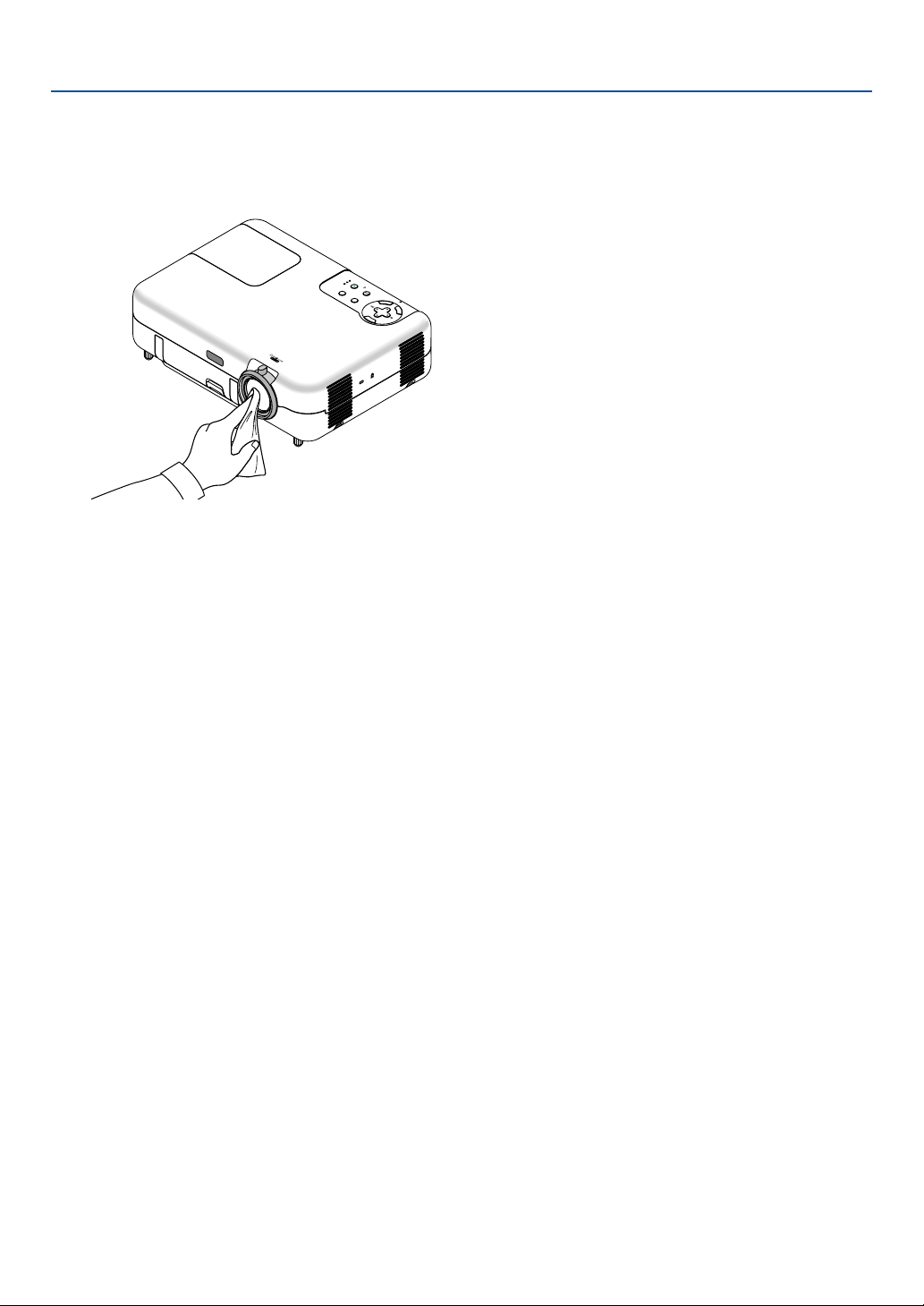
106
8. Maintenance
Cleaning the Lens
CAUTION
Tu rn off the projector, turn off the main power switch and unplug the projector before cleaning lens.
Z
O
O
M
FOCUS
3D REFORM
SOURCE
S
E
L
E
C
T
STATUS
LAMP
PC CARD
POWER
ON/STAND BY
AUTO ADJUST
M
E
N
U
E
N
T
E
R
C
A
N
C
E
L
Use a blower or lens paper to clean the lens, and be careful not to scratch the lens.
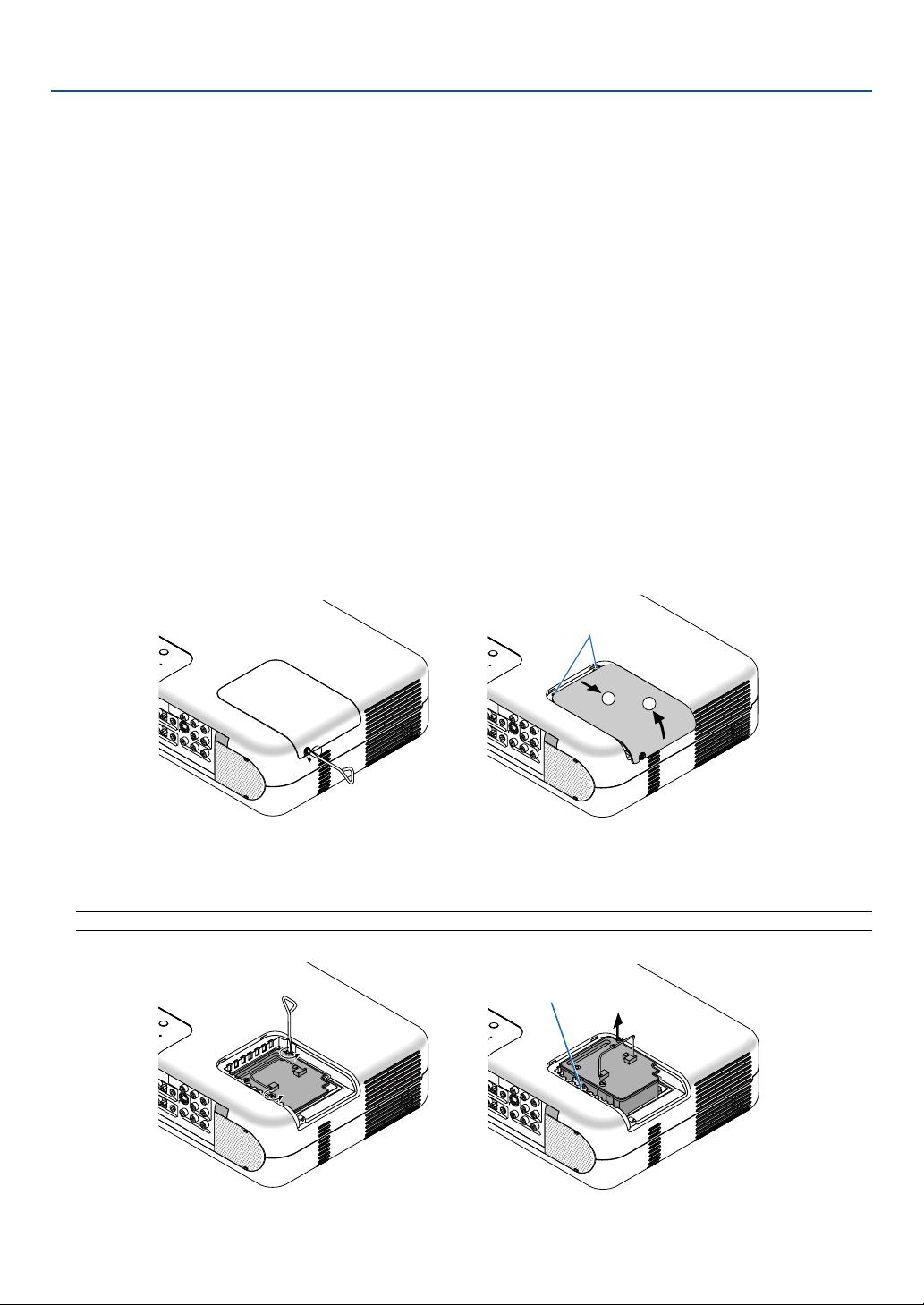
107
Replacing the Lamp and Filters
After your lamp has been operating for 2000 hours (up to 3000 hours in Eco mode) or longer, the LAMP indicator in the
cabinet will blink red and the message will appear. Even though the lamp may still be working, replace it at 2000 (up to
3000 hours in Eco mode) hours to maintain optimal projector performance.
CAUTION
• DO NOT TOUCH THE LAMP immediately after it has been used.
It will be extremely hot. Turn the projector off, wait 10 seconds, turn off the main power switch and then discon-
nect the power cable. Allow at least one hour for the lamp to cool before handling.
• DO NOT REMOVE ANY SCREWS except the lamp cover screw and two lamp case screws. You could receive
an electric shock.
• The projector will turn off and go into stand by mode after 2100 (up to 3100 hours in Eco mode) hours of
service. If this happens, be sure to replace the lamp. If you continue to use the lamp after 2000 hours (up to
3000 hours in Eco mode) of use, the lamp bulb may shatter, and pieces of glass may be scattered in the lamp
case. Do not touch them as the pieces of glass may cause injury. If this happens, contact your NEC dealer for
lamp replacement.
To replace the lamp:
1. Loosen the lamp cover screw until the screwdriver goes into a free-wheeling condition and remove the
lamp cover. The lamp cover screw is not removable.
8. Maintenance
2. Loosen the two screws securing the lamp housing until the screw-driver goes into a freewheeling
condition. The two screws are not removable.
Remove the lamp housing by pulling out the handle.
NOTE: There is an interlock on this case to prevent the risk of electrical shock. Do not attempt to circumvent this interlock.
S
TATUS
LAMP
OW
ER
A
D
J
U
S
T
COMPONENT
Y
Cb/Pb Cr/Pr
AUDIO
AUDIO
AUDIO
AUDIO
L/MONO
S-VIDEO
R 1
R 2
R
L/MONO
VIDEO
R
STATUS
LAMP
OW
ER
AD
JUST
COMPONENT
Y Cb/Pb Cr/Pr
AUDIO
AUDIO
AUDIO
AUDIO
L/MONO
S-VIDEO
ER 1
ER 2
R
L/MONOVIDEO R
1
2
Catch
S
T
A
T
U
S
L
A
M
P
O
W
E
R
A
D
JU
S
T
C
O
M
P
O
N
E
N
T
YCb
/P
b
C
r/P
r
A
U
D
IO
A
U
D
IO
A
U
D
IO
A
U
D
IO
L
/M
O
N
O
S
-V
ID
E
O
E
R
1
R
2
R
L
/M
O
N
O
V
ID
E
O
R
S
T
A
T
U
S
L
A
M
P
P
O
W
E
R
AD
JUST
C
O
M
P
O
N
E
N
T
YC
b
/P
b
C
r
/P
r
A
U
D
IO
A
U
D
IO
A
U
D
IO
A
U
D
IO
L
/M
O
N
O
S
-V
ID
E
O
E
R
1
E
R
2
R
L
/M
O
N
O
V
ID
E
O
R
Interlock
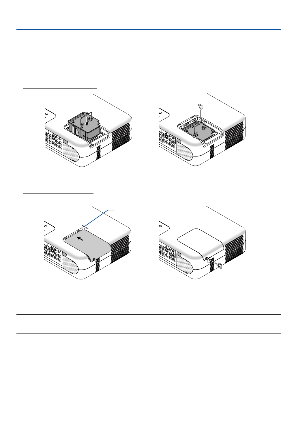
108
3. Insert a new lamp housing until the lamp housing is plugged into the socket.
CAUTION
Do not use a lamp other than the NEC replacement lamp (VT77LP).
Order this from your NEC dealer.
Secure it in place with the two screws.
Be sure to tighten the screws.
8. Maintenance
4. Reattach the lamp cover.
Tighten the lamp cover screw.
Be sure to tighten the screw.
5. After you install a new lamp, select the menu
→
[Setup]
→
[Page 5]
→
[Lamp Hour]
→
[Clear Lamp Hour
Meter], and then press “Clear” to clear the lamp usage hours.
NOTE: When the lamp exceeds 2100 hours (up to 3100 hours in Eco mode) of service, the projector cannot turn on and the menu
is not displayed. If this happens, press the Help button on the remote control for a minimum of 10 seconds while in standby
mode. When the lamp time clock is reset to zero, the LAMP indicator goes out.
STATUS
LAMP
PO
WER
AD
JUST
COMPONENT
Y Cb/Pb Cr/Pr
AUDIO
AUDIO
AUDIO
AUDIO
L/MONO
S-VIDEO
ER 1
ER 2
R
L/MONOVIDEO R
S
T
A
T
U
S
L
A
M
P
O
W
E
R
A
D
J
U
S
T
COMPO
NENT
Y
Cb/Pb Cr/Pr
AUDIO
AUD
IO
AUDIO
AUDIO
L/M
ON
O
S-VIDEO
R 1
R
2
R
L/M
ON
O
VID
EO
R
S
T
A
T
U
S
L
A
M
P
O
W
E
R
AD
JUST
C
O
M
P
O
N
E
N
T
Y
C
b
/P
b
C
r/P
r
A
U
D
IO
A
U
D
IO
A
U
D
IO
A
U
D
IO
L
/M
O
N
O
S
-V
ID
E
O
E
R
1
E
R
2
R
L
/M
O
N
O
V
ID
E
O
R
S
TA
T
U
S
LA
M
P
O
W
ER
ADJ
UST
C
O
M
P
O
N
E
N
T
YC
b
/P
b
C
r/P
r
A
U
D
IO
A
U
D
IO
A
U
D
IO
A
U
D
IO
L
/M
O
N
O
S
-V
ID
E
O
R
1
R
2
R
L
/M
O
N
O
V
ID
E
O
R
Allow about 0.4"
(1 cm) of space.
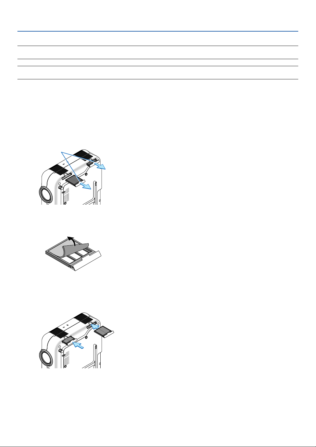
109
Replacing the Filters
NOTE: Do not wash the filter with soap and water. Soap and water will damage the filter membrane. Before replacing the filter,
remove dust and dirt from the projector cabinet. Keep out dust and dirt during filter replacement.
NOTE: When you replace the lamp, it is also wise to replace the filters. The filters come in the same package with your replace-
ment lamp.
CAUTION
•Turn off the projector, turn off the main power switch and unplug the projector before replacing the filters.
• Do not attempt to operate the projector without the two filter covers.
To replace the filters (sponge)
1. Remove the filter by pushing on the catch and pull it.
8. Maintenance
2. Gently peel off the filter (sponge) and replace it with the new one.
3. Reinstall the new filter cover.
The two filter covers are interchangeable.
To reset the filter usage time, from the menu, select [Setup] → [Page 5] → [Filter Usage] → [Clear Filter Usage Meter].
See also page 98 for resetting the filter usage time.
Catch

110
9
Appendix
○○○○○○○○○○○○○○○○○○○○○○○○○○○○○○○○○○○○○○○○
Troubleshooting ...................................................... 111
Specifications ......................................................... 114
Cabinet Dimensions ............................................... 116
Pin Assignments of D-Sub COMPUTER 1/2 Input
Connector............................................................. 117
Compatible Input Signal List ................................... 118
PC Control Codes and Cable Connection .............. 119
Using Software Keyboard ....................................... 120
TravelCare Guide .................................................... 121
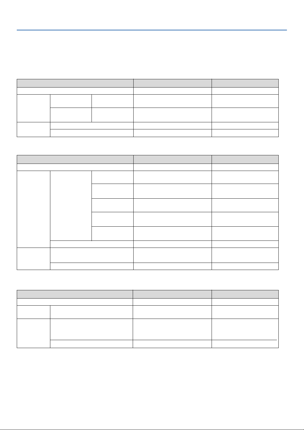
111
9. Appendix
Troubleshooting
This section helps you resolve problems you may encounter while setting up or using the projector.
Indicator Messages
Power Indicator
Indicator Condition
Projector Condition Note
Off
Blinking light
Steady light
Green
Orange
Green
Orange
0.5 sec On,
0.5 sec Off
0.5 sec On,
0.5 sec Off
The main power is off
The projector is getting ready to turn on.
The projector is cooling down.
The projector is turned on.
The projector is in Power-saving or Idle.
–
Wait for a moment.
Wait for a moment.
–
–
Status Indicator
Indicator Condition
Projector Condition Note
Off
Blinking light
Steady light
Red
Green
Orange
Green
1 cycle (0.5 sec On,
2.5 sec Off)
2 cycle (0.5 sec On,
0.5 sec Of)
3 cycle (0.5 sec On,
0.5 sec Off)
4 cycle (0.5 sec On,
0.5 sec Off)
6 cycle (0.5 sec On,
0.5 sec Off)
Normal
Lamp cover error
Temperature error
Power error
Fan error
Lamp error
Re-firing the lamp
Cabinet button is locked
Idle condition
–
Replace the lamp cover correctly.
The projector is overheated. Move
the projector to a cooler location.
Power unit will not work correctly.
Fans will not work correctly.
Lamp fails to light. Wait a full
minute and then turn on again.
The projector is re-firing.
You have pressed cabinet button
when Cabinet Button is locked.
–
Lamp Indicator
Indicator Condition
Projector Condition Note
Off
Blinking light
Steady light
Normal
Lamp has reached its end of life. Lamp
replacement message will be displayed.
Lamp has been used beyond its limit. The
projector will not turn on until the lamp is
replaced.
Lamp mode is set to Eco mode
Red
Red
Green
–
Replace the lamp.
Replace the lamp.
–

112
9. Appendix
Common Problems & Solutions (See also "Power/Status/Lamp Indicator" on page 111.)
Does not turn on
Will turn off
No picture
Picture suddenly
becomes dark
Color tone or hue is
unusual
Image isn’t square to
the screen
Picture is blurred
Image is scrolling
vertically, horizontally
or both
Remote control does
not work
Indicator is lit or
blinking
Cross color in RGB
mode
• Check that the power cable is plugged in and that the power button on the projector cabinet or the remote
control is on. See pages 28 and 30.
• Ensure that the lamp cover is installed correctly. See page 108.
• Check to see if the projector has overheated or the lamp usage exceeds 2100 hours (up to 3100 hours : Eco
mode). If there is insufficient ventilation around the projector or if the room where you’re presenting is par-
ticularly warm, move the projector to a cooler location.
• The lamp may fail to light. Wait a full minute and then turn on the power again.
• The lamp has reached the end of its usable life. Replace the lamp.
• Ensure that the Power Management is off. See page 95.
• Use the SOURCE button on the projector cabinet or the VIDEO, the S-VIDEO, the COMPONENT, the COM-
PUTER 1/2 or the VIEWER button on the remote control to select your source (Computer 1/2, Component,
Video, S-Video or Viewer). See page 32.
• Ensure your cables are connected properly.
• Use menus to adjust the brightness and contrast. See page 78.
• Remove the lens cap.
• Reset the settings or adjustments to factory preset levels using the Reset in the Menu. See page 101.
• Enter your registered keyword if the Security function is enabled. See page 49.
• When using with a notebook PC, be sure to connect between the projector and the notebook PC before turning
on the power to the notebook PC. In most cases signal cannot be output from RGB output unless the notebook
PC is turned on after connecting with the projector.
* If the screen goes blank while using your remote control, it may be the result of the computer's screen-
saver or power management software.
* If you accidentally hit the POWER button on the remote control, wait 60 seconds and then press the POWER
button again to resume.
• See also the next page.
• When one of the following happens, the Lamp mode automatically changes from Normal to Eco.
* When there are no signals (blue or black screen) → To return to the Normal mode, select another available
source.
* When the image is muted using the PIC-MUTE button on the remote control → Press the PIC-MUTE button
again to return to the Normal mode.
* When the room where you' re presenting is particularly warm → Move the projector to a cooler location.
• Check if an appropriate color is selected in "Wall Color". If so, select an appropriate option. See page 80.
• Adjust "Hue" in "Picture". See page 78.
• Reposition the projector to improve its angle to the screen. See page 33.
• Use the 3DReform function to correct the trapezoid distortion. See page 35.
• Adjust the focus. See page 34.
• Reposition the projector to improve its angle to the screen. See page 33.
• Ensure that the distance between the projector and screen is within the adjustment range of the lens. See page
22.
• Condensation may form on the lens if the projector is cold, brought into a warm place and is then turned on.
Should this happen, let the projector stand until there is no condensation on the lens.
• Use the SOURCE button on the projector cabinet or the VIDEO, the S-VIDEO, the COMPONENT, the COM-
PUTER 1/2 or the VIEWER button on the remote control to select your source (Video, S-Video, Component,
Computer or Viewer). See page 32.
• Adjust the computer image manually with the Pixel Adjust/Position in the Image. See page 84.
• Install new batteries. See page 19.
• Make sure there are no obstacles between you and the projector.
• Stand within 22 feet (7 m) of the projector. See page 19.
• Check if one or more remote sensors are enabled. Select [Setup] → [Page 4] → [Remote Sensor] from the
menu. See page 97.
• Make sure that you are in the Projector mode and the PJ button lights in red. If not, press the PJ button. See
page 40.
• See the POWER/STATUS/LAMP Indicator on page 111.
• Press the AUTO ADJUST button on the projector cabinet or the AUTO ADJ. button on the remote control. See
page 37.
• Adjust the computer image manually with the Pixel Adjust/Position in the Image. See page 84.
Problem Check These Items
For more information contact your dealer.

113
9. Appendix
If there is no picture, or the picture is not displayed correctly.
• Power on process for the projector and the PC.
Be sure to connect the RGB cable between the projector and the computer before turning on the computer.
There are some notebook PCs, which do not output signal unless there is a projectors or monitor connected
first.
NOTE: You can check the horizontal frequency of the current signal in the projector’s menu under ‘Menu
→
Help
→
Informa-
tion. If it reads “0kHz”, this means there is no signal being output from the computer. See page 100 or go to next step.
• Enabling the computer’s external display.
Displaying an image on the notebook PC’s screen does not necessarily mean it outputs a signal to the projec-
tor. When using a PC compatible laptop, a combination of function keys will enable/disable the external display.
Usually, the combination of the ‘Fn” key along with one of the 12 function keys gets the external display to come
on or off. For example, NEC laptops use Fn + F3, while Dell laptops use Fn + F8 key combinations to toggle
through external display selections.
• Non-standard signal output from the computer
If the output signal from a notebook PC is not an industry standard, the projected image may not be displayed
correctly. Should this happen, deactivate the notebook PC’s LCD screen when the projector display is in use.
Each notebook PC has a different way of deactivate/reactivate the local LCD screens as described in the
previous step. Refer to your computer’s documentation for detailed information.
• Image displayed is incorrect when using a Macintosh
When using a Macintosh with the projector, set the DIPswitch of the Mac adapter (not supplied with the projec-
tor) according to your resolution. After setting, restart your Macintosh for the changes to take affect.
For setting display modes other than those supported by your Macintosh and the projector, changing the DIP
switch on a Mac adapter may bounce an image slightly or may display nothing. Should this happen, set the DIP
switch to the 13” fixed mode and then restart your Macintosh. After that, restore the DIP switches to a
displayable mode and then restart the Macintosh again.
NOTE: A Video Adapter cable manufactured by Apple Computer is needed for a PowerBook which does not have a mini D-Sub
15-pin connector.
• Mirroring on a PowerBook
* When using the projector with a Macintosh PowerBook, output may not be set to 1024 x 768 unless “mirror-
ing” is off on your PowerBook. Refer to owner’s manual supplied with your Macintosh computer for mirroring.
• Folders or icons are hidden on the Macintosh screen
Folders or icons may not be seen on the screen. Should this happen, select [View] ->[Arrange] from the Apple
menu and arrange icons.

114
9. Appendix
Specifications
This section provides technical information about the VT770 Projector's performance.
Model Number VT770
Optical
LCD Panel 0.8" p-Si TFT active-matrix with Micro Lens Array
Resolution 1024 768 pixels* native, up to UXGA with Advanced AccuBlend
Lens Manual zoom and focus:
F1.7 - 2.0 f=24.0 - 28.8mm
Lamp 200W (152W Eco mode)
Image Size 25 - 300 inches (0.6 - 7.6 m) diagonal
Projection Distance 2.38 - 35.8 ft / 0.7 (Wide) - 11 m (Tele)
Projection Angle Tele : 9.5° - 9.9° Wide : 11.4° - 12.1°
Electrical
Inputs 2 RGB (D-Sub 15 Pin), 1 Component (RCA3 [YCbCr]),
1 S-Video (DIN 4 Pin), 1 Video (RCA), 2 Stereo Mini Audio,
2 (L/R) RCA Audio, 1 PC Control (D-Sub 9 Pin)
Outputs 1 RGB (D-Sub 15 Pin), 1 Stereo Mini Audio
USB Port 1 A Type, 1 B Type
PC Card 1 Slot
Video Compatibility NTSC, NTSC4.43, PAL, PAL-60, PAL-N, PAL-M, SECAM, HDTV: 1080i,
1080i/50Hz, 720p, 576p, 480p, 480i, 576i/50Hz
Scan Rate Horizontal: 15 kHz to 100 kHz (RGB: 24 kHz or over)
Ver tical: 50 Hz to 120 Hz
Video Bandwidth RGB: 80 MHz (-3dB)
Color Reproduction 16.7 million colors simultaneously, Full color
Horizontal Resolution NTSC / NTSC4.43/PAL/PAL-M/PAL-N/PAL60: 540 TV lines
SECAM: 300 TV lines
RGB: 1024 dots (H) 768 dots (V)
External Control RS232, IR
Sync Compatibility Separate Sync / Composite Sync / Sync on G
Built-in Speaker 5W 2
Power Requirement 100 - 240V AC, 50 / 60 Hz
Input Current 3.2A (100 - 240V AC)
Power Consumption 9W in Idle mode / 6W in Power-saving mode /
280W in Lamp Normal mode /
225W in Lamp Eco mode

115
Mechanical
Installation Orientation Desktop/Front, Desktop/Rear, Ceiling/Front, Ceiling/Rear
Dimensions 13.4" (W) 3.8" (H) 9.6" (D)
340mm (W) 97mm (H) 245mm (D)
(not including protrusions)
Net Weight 7.9 lbs / 3.6 kg
Environmental Considerations Operational Temperatures : 32° to 95°F (0° to 35°C),
20% to 80% humidity (non-condensing)
Storage Temperatures : 14° to 122°F (-10° to 50°C), 20% to 80% humidity
(non-condensing)
Regulations UL Approved (UL 60950, CSA 60950)
Meets DOC Canada Class B requirements
Meets FCC Class B requirements
Meets AS/NZS Cispr. 22: Class B
Meets EMC Directive (EN55022, EN55024, EN61000-3-2,
EN61000-3-3)
Meets Low Voltage Directive (EN60950, TUV GS Approved)
* Effective pixels are more than 99.99%.
For additional information visit:
US : http://www.necvisualsystems.com
Europe : http://www.nec-europe.com/
Global : http://www.nec-pj.com/
The specifications are subject to change without notice.
9. Appendix
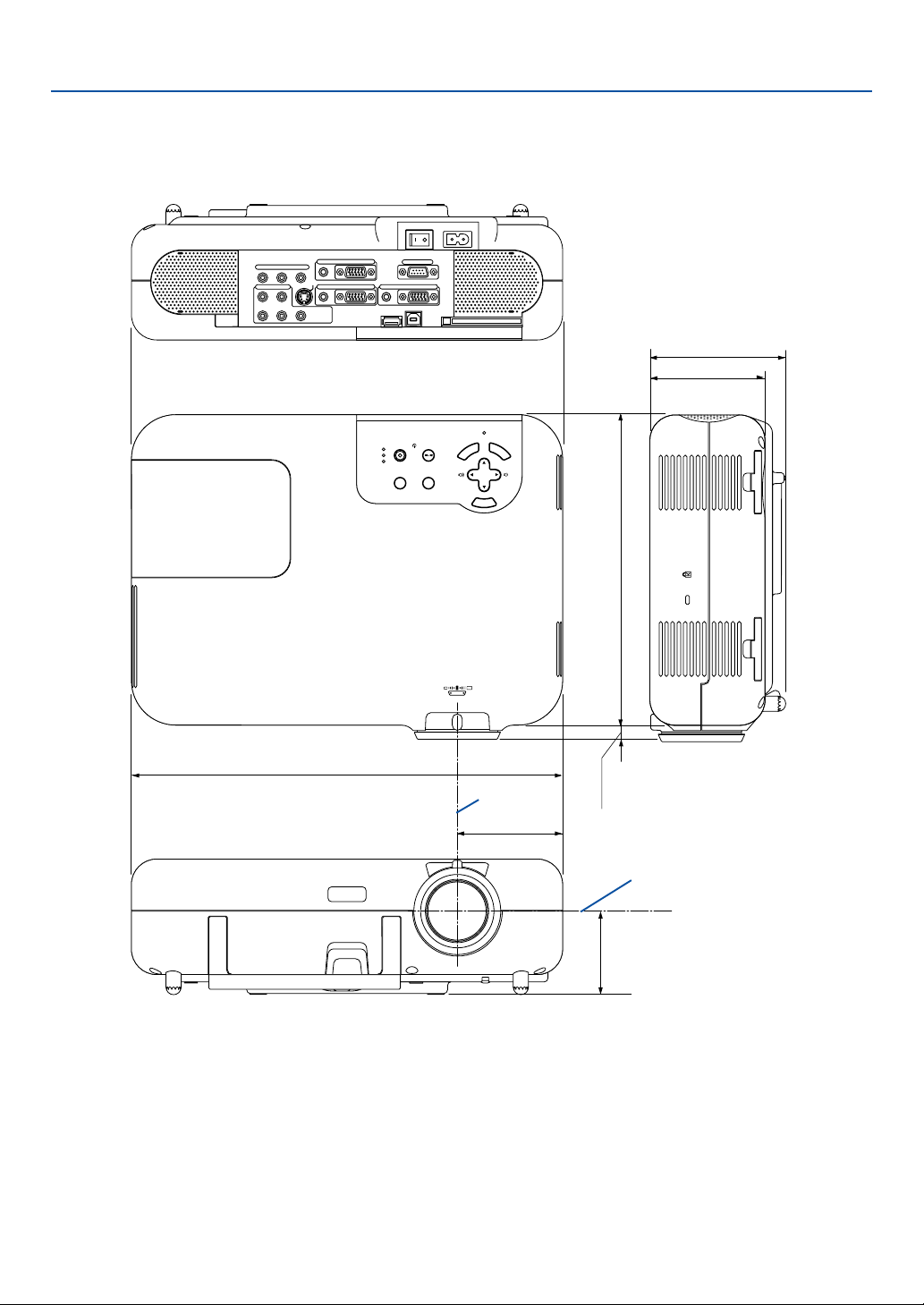
116
9. Appendix
Cabinet Dimensions
AC IN
COMPONENT
YCb/Pb Cr/Pr
AUDIO
AUDIO
AUDIO
AUDIO
L/MONO
S-VIDEO
COMPUTER 1AUDIO
PC CARD
USB(COMPUTER)
USB(MOUSE)
MONITOR OUT
COMPUTER 2
PC CONTROL
R
L/MONOVIDEO R
3D REFORM
SOURCE
SELECT
STATUS
LAMP
PC CARD
POWER
ON/STAND BY
AUTO ADJUST
M
E
N
U
E
N
T
E
R
C
A
N
C
E
L
ZOOM
FOCUS
83 (3.27")
340 (13.4")
107 (4.2")
97 (3.8")
65.8 (2.6")
245 (9.65")
11.2-14.6
(0.44-0.57")
Lens center
Lens center
Unit: mm (inch)
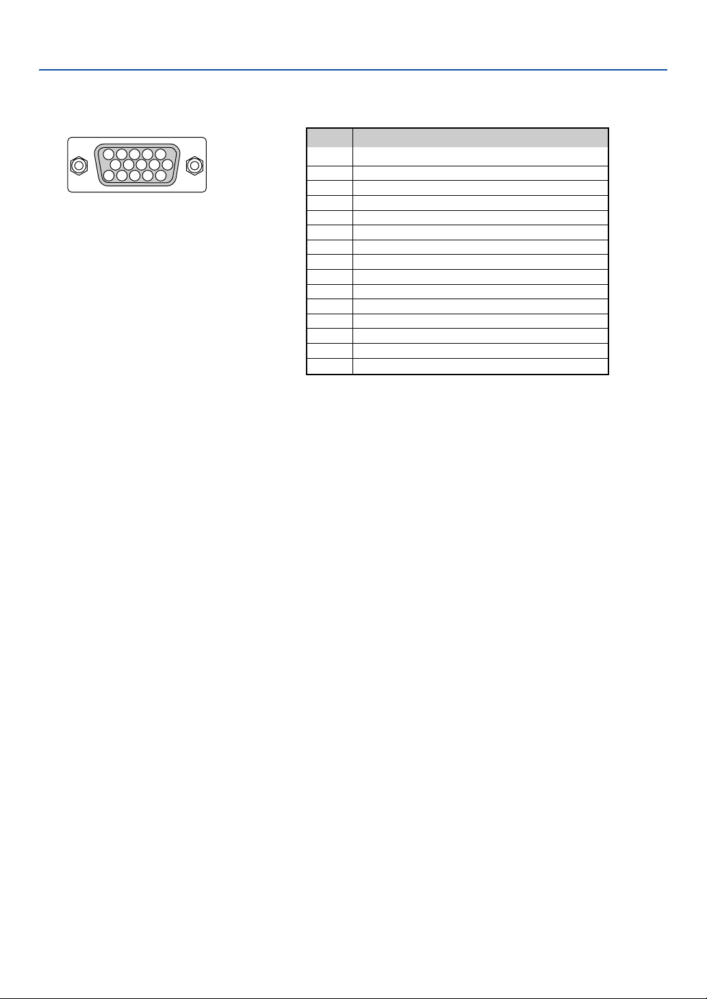
117
Mini D-Sub 15 Pin Connector
Pin Assignments of D-Sub COMPUTER 1/2 Input Connector
Pin No. RGB Signal (Analog)
1 Red
2 Green or Sync on Green
3 Blue
4 Ground
5 Ground
6 Red Ground
7 Green Ground
8 Blue Ground
9 No Connection
10 Sync Signal Ground
11 SCART Sync*
1
12 Bi-directional DATA (SDA)*
2
13 Horizontal Sync or Composite Sync
14 Vertical Sync
15 Data Clock
Signal Level
Video signal : 0.7Vp-p (Analog)
Sync signal : TTL level
51423
10
1112131415
6978
9. Appendix
*1 COMPUTER 2 input only
*2 COMPUTER 1 input only

118
9. Appendix
Compatible Input Signal List
Signal Resolution Frequency H. Refresh Rate
( Dots ) ( kHz ) ( Hz )
NTSC – 15.734 60
PA L–15.625 50
PAL60 – 15.734 60
SECAM – 15.625 50
VESA 640 480 31.47 59.94
IBM 640 480 31.47 60
MAC 640 480 31.47 60
MAC 640 480 34.97 66.67
MAC 640 480 35 66.67
VESA 640 480 37.86 72.81
VESA 640 480 37.5 75
IBM 640 480 39.375 75
VESA 640 480 43.269 85.01
IBM 720 350 31.469 70.09
VESA 720 400 37.927 85.04
IBM 720 350 39.44 87.85
IBM 720 400 39.44 87.85
VESA 800 600 35.16 56.25
VESA 800 600 37.879 60.32
VESA 800 600 48.077 72.19
VESA 800 600 46.88 75
VESA 800 600 53.674 85.06
MAC 832 624 49.725 74.55
VESA 1024 768 35.5 43 Interlaced
VESA 1024 768 48.363 60
VESA 1024 768 56.476 70.07
MAC 1024 768 60.241 74.93
VESA 1024 768 60.023 75.03
VESA 1024 768 68.677 85
# VESA 1152 864 67.5 75
#MAC 1152 870 68.681 75.06
# SUN 1152 900 61.796 65.95
# SGI 1152 900 71.736 76.05
# VESA 1280 960 60 60
# VESA 1280 1024 63.981 60.02
#MAC 1280 1024 69.89 65.18
#HP 1280 1024 78.125 72.01
# SUN 1280 1024 81.13 76.11
# VESA 1280 1024 79.976 75.03
# VESA 1280 1024 91.146 85.02
# SXGA+ 1400 1050 – –
# HDTV (1080p) 1920 1080 67.5 60 Progressive
# SDTV(576i)(625i) – 15.6 50
# SDTV(576p)(625p) – 31.5 50
#
HDTV (1080i)(1125i)
1920 1080 33.75 60 Interlaced
#
HDTV (1080i)(1125i)
1920 1080 28.125 50 Interlaced
#
HDTV (720p)(750p)
1280 720 45 60 Progressive
# SDTV (480p)(525p) – 31.47 59.94 Progressive
# VESA 1600 1200 75.0 60
# VESA 1600 1200 81.25 65
# VESA 1600 1200 87.5 70
# VESA 1600 1200 93.75 75
DVD YCbCr – 15.734 59.94 Interlaced
DVD YCbCr – 15.625 50 Interlaced
#: Images in above flagged with # are compressed with Advanced AccuBlend.
NOTE: Some composite sync signals may not be displayed correctly.
Signals other than those specified in the table above may not be displayed correctly. If this should happen, change the refresh
rate or resolution on your PC. Refer to Display Properties help section of your PC for procedures.
UXGA (1600
1200) is supported for separate sync signal only.

119
9. Appendix
Cable Connection
Communication Protocol
Baud rate ........................................ 38400 bps
Data length ..................................... 8 bits
Parity .............................................. No parity
Stop bit .......................................... One bit
X on/off .......................................... None
Communications procedure ........... Full duplex
NOTE: Depending on the equipment, a lower baud rate may be recommended for long cable runs.
PC Control Codes and Cable Connection
PC Control Codes
Function Code Data
POWER ON 02H 00H 00H 00H 00H 02H
POWER OFF 02H 01H 00H 00H 00H 03H
INPUT SELECT COMPUTER 1 02H 03H 00H 00H 02H 01H 01H 09H
INPUT SELECT COMPUTER 2 02H 03H 00H 00H 02H 01H 02H 0AH
INPUT SELECT VIDEO 02H 03H 00H 00H 02H 01H 06H 0EH
INPUT SELECT S-VIDEO 02H 03H 00H 00H 02H 01H 0BH 13H
INPUT COMPONENT 02H 03H 00H 00H 02H 01H 1AH 22H
INPUT SELECT VIEWER 02H 03H 00H 00H 02H 01H 1FH 27H
PICTURE MUTE ON 02H 10H 00H 00H 00H 12H
PICTURE MUTE OFF 02H 11H 00H 00H 00H 13H
SOUND MUTE ON 02H 12H 00H 00H 00H 14H
SOUND MUTE OFF 02H 13H 00H 00H 00H 15H
ON SCREEN MUTE ON 02H 14H 00H 00H 00H 16H
ON SCREEN MUTE OFF 02H 15H 00H 00H 00H 17H
NOTE: Contact your local dealer for a full list of PC Control Codes if needed.
15243
67 98
To GND of PC
NOTE: Pins 1, 4, 6 and 9 are no used.
NOTE: Jumper “Request to Send” and “Clear to Send”
together on both ends of the cable to simplify cable
connection.
To RxD of PC
To TxD of PC
To RTS of PC
To CTS of PC
PC Control Connector (D-SUB 9P)

120
9. Appendix
Using Software Keyboard
1 to 0 and Characters
.............................. Use to type in password or keyword.
MODE .................... Selects one of three modes for alphabet and special characters.
SP ......................... Inserts a space
BS ......................... Deletes one character backward
왗 .......................... Returns to the previous
왘 .......................... Advances to the next
OK ......................... Executes the selection
Cancel ................... Cancels the selection
NOTE: You can drag the Software keyboard on the screen by clicking and holding any part on the keyboard except buttons.

121
9. Appendix
TravelCare Guide
TravelCare - a service for international travelers
This product is eligible for "TravelCare", NEC's unique international war-
ranty.
Please note that TravelCare coverage differs in part from coverage un-
der the warranty included with the product.
Services offered with TravelCare
This warranty allows customers to receive service on their product at
the NEC and NEC-designated service stations in the countries listed
herein when temporarily traveling internationally for business or plea-
sure.
For details on services offered by the different service stations, please
refer to the "List of TravelCare Outlets" below.
1 Repair services
The product will be repaired and delivered within 10 business days,
not including shipping time.
During the term of warranty, the cost of maintenance parts, labor
costs for repairs and shipping costs within the service station's cov-
erage area are covered by the warranty.
2 Replacement product rental service
If the customer desires, he or she can rent a replacement product
while the original product is being repaired.
Fee: US$200 for 12 days
This fee must be paid at the local service station in cash or credit
card.
The $200 rental fee is non-refundable even if the customer rents it
less than 12 days before returning.
The replacement product will be delivered within 3 business days.
If the customer did not return the replacement product within 12 days,
the customer will be charged the price of the unit.
If the customer returned the replacement product in a faulty or dam-
aged condition, the repair cost will be charged to the customer.
Note that this service is not offered in all countries and regions. Please
refer to the "List of TravelCare Outlets".
In addition, this replacement product rental service is not offered af-
ter the product's warranty has expired.
Term of warranty
1
a. Upon presentation of the warranty or receipt received upon pur-
chase:
Valid for the term indicated on the warranty or the normal term of
warranty for the country of purchase.
b. When only the product is brought in:
Valid for a period of within 14 months of the date of manufacture
indicated by the serial number attached to the product.
2 When a product whose term of warranty is expired is brought in:
Repairs will be offered for a fee. In this case the customer is not
eligible for the replacement product rental service.
3 In the following cases, repairs may be charged, even if the product's
warranty is still in effect:
1) If the term of warranty, model name, serial number and name of
the store of purchase are not indicated on the warranty or have
been altered.
2) Problems or damage caused by dropping or shocks during ship-
ment or movement by the customer or by improper handling by
the customers.
3) Problems or damage caused by improper usage or unwarrant-
able alterations or repairs by the customer.
4) Problems or damage caused by fire, salt damage, gas damage,
earthquakes, lightning damage, storm or flood damage or other
natural disasters or such external factors as dust, cigarette
smoke, abnormal voltage, etc.
5) Problems or damage caused by use in hot or humid places, in
vehicles, boats or ships, etc.
6) Problems or damage caused by expendable supplies or devices
connected to the product other than those designated by NEC.
7) Problems caused by natural consumption, wear or deterioration
of parts under normal usage conditions.
8) Problems or damage to lamps and other expendable supplies,
included parts or optional parts.
9) Other conditions stipulated in the warranty included with the prod-
uct also apply.
NOTE: The product can be used overseas with voltages of 100 to 120V and 200
to 240V by using a power cable suited for the standards and power source volt-
age of the country in which the product is being used.
List of TravelCare Outlets
This list applies as of June 1, 2002.
For the most up-to-date information, please refer to the websites of the
service stations in the various countries on the List of TravelCare Out-
lets or to the NEC website at http://www.nec-pj.com.
In Europe
NEC Europe, Ltd. / European Technical Centre
Address: Unit G, Stafford Park 12, Telford TF3 3BJ, U.K.
Telephone: +44 1952 237000
Fax Line: +44 1952 237006
Email Address: [email protected].com
WEB Address: http://www.neceur.com
(Regions Covered)
EU: Austria*, Belgium*, Denmark*, Finland*, France*, Germany*,
Greece*, Ireland*, Italy*, Luxembourg*, The Netherlands*,
Portugal*, Spain*, Sweden* and the United Kingdom*
EEA: Norway*, Iceland and Liechtenstein
In North America
NEC Solutions (America), Inc.
Address: 1250 Arlington Heights Road, Itasca,
Illinois 60143, U.S.A.
Telephone: +1 800 836 0655
Fax Line: +1 800 356 2415
Email Address: vsd-tech-suppor[email protected]
WEB Address: http://www.necvisualsystems.com
(Regions Covered)
U.S.A. *, Canada*
In Oceania
NEC Australia Pty., Ltd.
Address: New South Wales;
184 Milperra Road, Reversby 2212
Victoria;
480 Princess Hwy Noble Park 3174
South Australia;
84A Richmond Road, Keswick 5035
Queensland;
116 Ipswich Road, Woollongabba 4102
Western Australia;
45 Sarich Court Osborne Park 6017
Telephone: 131 632 (from domestic)
+61 8 8375 5706 (from overseas)
Fax Line: +61 8 8375 5757
Email Address: [email protected]
WEB Address: http://www.nec.com.au
(Regions Covered)
Australia*, New Zealand

122
In Asia and Middle East
NEC Viewtechnology, Ltd.
Address: 686-1, Nishioi, Oi-Machi, Ashigarakami-Gun,
Kanagawa 258-0017, Japan
Telephone: +81 465 85 2369
Fax Line: +81 465 85 2393
Email Address: suppor[email protected].jp
WEB Address: http://www.nec-pj.com
(Regions Covered)
Japan*
NEC Hong Kong Ltd.
Address: 11th Floor, Tower B, New Mandarin Plaza, 14
Science Museum Road,
Tsim Sha Tsui East, Kowloon, Hong Kong
Telephone: +852 2369 0335
Fax Line: +852 2795 6618
Email Address: [email protected]
WEB Address: http://www.nec.com.hk
(Regions Covered)
Hong Kong
NEC Taiwan Ltd.
Address: 7F, No.167, SEC.2, Nan King East Road, Taipei,
Taiwan, R.O.C.
Telephone: +886 2 8500 1734
Fax Line: +886 2 8500 1420
Email Address: [email protected]
WEB Address: http://www.nec.com.tw
(Regions Covered)
Taiwan
NEC Solutions Asia Pacific Pte. Ltd
Address: 401 Commonwealth Drive, #07-02, Haw Par
Technocentre, Singapore 149598
Telephone: +65 6 273 8333
Fax Line: +65 6 274 2226
Email Address: [email protected].nec.com.sg
WEB Address: http://www.nec.com.sg/ap
(Regions Covered)
Singapore
Nautilus Hyosung Inc.
Address: 7th Floor, Cheongdam Building, 52,
Cheongdam-Dong,
Kangnam-Ku, Seoul, Korea 135-100
Telephone: +82 2 510 0234
Fax Line: +82 2 540 3584
Email Address: hds-ykc@hyosung.com
(Regions Covered)
South Korea
Lenso Communication Co., Ltd.
Address: 292 Lenso House 4, 1st Floor, Srinakarin Road,
Huamark, Bangkapi, Bangkok 10240, Thailand
Telephone: +66 2 375 2425
Fax Line: +66 2 375 2434
Email Address: pattara@lenso.com
WEB Address: http://www.lenso.com
(Regions Covered)
Thailand
ABBA Electronics L.L.C.
Address: Tariq Bin Ziyad Road, P.O.Box 327, Dubai,
United Arab Emirates
Telephone: +971 4 371800
Fax Line: +971 4 364283
Email Address: [email protected]
(Regions Covered)
United Arab Emirates
Samir Photographic Supplies
Address: P.O.Box 599, Jeddah 21421, Saudi Arabia
Telephone: +966 2 6828219
Fax Line: +966 2 6830820
Email Address: [email protected]
(Regions Covered)
Saudi Arabia
NOTE: In countries designated with an asterisk(*), replacement product rental
service are offered.
9. Appendix

123
TO: NEC or NEC’s Authorized Service Station:
FM:
(Company & Name with signature)
Dear Sir (s),
I would like to apply your TravelCare Service Program based on attached registration and qualification sheet and agree with your
following conditions, and also the Service fee will be charged to my credit card account, if I don’t return the Loan units within the
specified period. I also confirm following information is correct. Regards.
Application Sheet for TravelCare Service Program
Date: / / ,
P-1/ ,
Country,
product purchased :
User’s Company Name :
User’s Company Address :
Phone No., Fax No. :
User’s Name :
User’s Address :
Phone No., Fax No. :
Local Contact office :
Local Contact office Address :
Phone No., Fax No. :
User’s Model Name :
Date of Purchase :
Serial No. on cabinet :
Problem of units per User :
Required Service : (1) Repair and Return (2) Loan unit
Requested period of Loan unit :
Payment method : (1) Credit Card (2) Travelers Cheque (3) Cash
In Case of Credit Card :
Card No. w/Valid Date :
9. Appendix

124
Condition of your TravelCare Service Program
Enduser is requested to understand following conditions of TravelCare
Service Program and complete the necessary information on the appli-
cation sheet.
1. Service Options:
There are 3 types of "Service" available. Enduser has to understand
following condition and is required to fill in the Application Sheet.
1) Repair and Return:
The 'Faulty unit' is sent or collected from the customer. It is repaired
and returned within 10 days to the customer, excluding transport time.
There may have a case, repair and return can't be done by NEC
Authorized Service Station, because of shortage of spare parts due
to same model is not sold in the territory.
2) Repair and Return with Loan: (This service is limited to some Ser-
vice Stations)
This service is offered to the Enduser, who cannot wait until their unit
is repaired.
The customer can borrow a unit for $200 up to 12 days. Customer
then sends in inoperable unit to nearest NEC Authorized Service
Station for service. In order to prevent collection problem, Enduser is
required to fill in Application Sheet.
Enduser needs to confirm the availability of the Service to NEC Au-
thorized Service Stations.
3) Loan Only:
For this service, NEC Authorized Service Station supplies the cus-
tomer with a loan unit for US$200 up to 12 days. Customer keeps the
inoperable unit and when customer returns home, customer arranges
to have the projector serviced in the home country.
2. Warranty Exclusions:
This program does not apply if the Projector's serial number has been
defaced, modified or removed.
If, in the judgement of NEC Authorized Service Station or its agent the
defects or failures result from any cause other than fair wear and tear or
NEC neglect, or fault including the following without limitation:
1) Accidents, transportation, neglect, misuse, abuse, water, dust, smoke
or default of or by the Customer its employees or agents or any third
party;
2) Failure or fluctuation of electrical power, electrical circuitry, air condi-
tioning, humidity control or other environmental conditions such as
use it in smoking area;
3) Any fault in the attachments or associated products or components
(whether or not supplied by NEC or its agents which do not form part
of the Product covered by this warranty);
4) Any act of God, fire, flood, war, act of violence or any similar occur-
rence;
5) Any attempt by any person other than any person authorized by NEC
to adjust, modify, repair, install or service the product.
6) Any Cross-border charges such as, duty, insurance, tax etc.
3. Charges for Warranty Exclusions and Out of Warranty Case:
In case faulty unit is under warranty exclusions case or under Out of
Warranty period, NEC Authorized Service Station will Inform estimation
of actual service cost to the Enduser with reason.
4. Dead on Arrival (DOA):
Enduser must take this issue up with their original supplier in the coun-
try of purchase.
NEC Authorized Service Station will repair the DOA unit as a Warranty
repair, but will not exchange DOA unit with new units.
5. Loan Service Charges and Conditions:
Upon acceptance of this NEC Projector, Customer agrees to assume
liability for this loan unit.
The current cost of use of this loan unit is $200.00 USD for 12 calendar
days.
If Customer does not return the unit within the 12 calendar days, Cus-
tomer will be charged the next highest cost up to and including the full
list price to Credit Cards, which price will be informed by NEC Autho-
rized Service Stations. Please see the attached listing of contacts for
each country to arrange for pickup of the loan unit.
If you return to their country of origin with the loan unit, you will be
charged additional freight to return the unit to the loaning country.
Thank you for your understanding of this program.
9. Appendix

NEC SOLUTIONS’ PROJECTOR PRODUCTS
NEC Solutions (America), Inc. (hereafter NEC Solutions) warrants
this product to be free from defects in material and workmanship
under the following terms.
HOW LONG IS THE WARRANTY
NEC Solutions’ VT770 projector is covered by a two (2) year
limited parts and labor warranty from the date of the first cus-
tomer purchase. The lamp when used under normal operating
conditions is warranted for 500 hours or 90 days, whichever
comes first.
WHO IS PROTECTED
This warranty may be enforced only by the first purchaser, and is
not transferable.
WHAT IS COVERED AND WHAT IS NOT COVERED
Except as specified below, this warranty covers all defects in
material or workmanship in this product.
NEC SOLUTIONS’ LIABILITY FOR ANY DEFECTIVE PRODUCT IS
LIMITED TO THE REPAIR OR REPLACEMENT OF THE PRODUCT
AT NEC SOLUTIONS’ OPTION. REPLACEMENT PRODUCTS MAY
BE NEW OR ‘LIKE NEW’. The following are not covered by the
limited warranty and NEC Solutions shall not be liable for:
1. Any product which is not distributed in the U.S.A. or Canada
by NEC Solutions or which is not purchased, installed, and
operated in the U.S.A or Canada.
2. Any product on which the serial number has been defaced,
modified or removed.
3. Normal decrease in lamp light output over time.
4. Damage, deterioration or malfunction resulting from:
a. Accident, misuse, abuse, neglect, improper ventilation, fire,
dust, smoke, water, lightning or other acts of nature, unau-
thorized product modification, or failure to follow instruc-
tions supplied with the product.
b. Repair or attempted repair by anyone other than a NEC
Solutions authorized service center.
c. Any shipment of the product (claims must be presented to
the carrier).
d. Removal or installation of the product.
e. Any other cause which does not relate to a product defect.
f. Use of the product beyond normal operating conditions.
Normal operating conditions are defined as product use
not in excess of 8 hours per day and 260 days per year.
5. Cartons, carrying cases, shipping cases, batteries, external
cabinets, magnetic tapes, or any accessories used in connec-
tion with the product.
6. Service required as a result of third party components.
WHAT NEC SOLUTIONS WILL PAY FOR
NEC Solutions will pay labor and material expenses for covered
items, but NEC Solutions will not pay for the following:
1. Removal or installation charges.
2. Costs of technical adjustments, set-up, maintenance, or adjust-
ment of user controls.
3. Payment of shipping and related charges incurred in returning
the product for warranty repair.
LIMITED WARRANTY (USA and Canada only)
HOW YOU CAN GET WARRANTY SERVICE
1. To obtain service on your product, consult the dealer from whom
you purchased the product.
2.
Whenever warranty service is required, the original dated invoice
(or a copy) must be presented as proof of warranty coverage. In
order to obtain warranty service, you may be required to describe
and demonstrate the problem to your dealer or to NEC Solutions.
3. All products returned to NEC Solutions for service MUST have
prior approval. To receive approval or for the name of the
nearest NEC Solutions authorized service center, call NEC
Solutions at 800-836-0655.
4. It shall be your obligation and expense to ship the product,
freight prepaid, or to deliver it to a NEC Solutions authorized
service center, in either the original package or a similar pack-
age affording an equal degree of protection.
5.
In the event a product is returned to NEC Solutions for warranty
service, and it is determined that there is no product defect or that
the product condition is not covered by this limited warranty, a
diagnostic service fee may be charged to the customer.
LIMITATION OF IMPLIED WARRANTIES
EXCEPT AS EXPRESSLY SET FORTH IN THIS LIMITED WARRANTY,
NEC SOLUTIONS MAKES NO OTHER WARRANTIES, EXPRESS
OR IMPLIED, INCLUDING BUT NOT LIMITED TO ANY IMPLIED
WARRANTIES OR CONDITIONS OF MERCHANTABILITY AND
FITNESS FOR A PARTICULAR PURPOSE. ANY IMPLIED WARRAN-
TIES THAT MAY BE IMPOSED BY LAW ARE LIMITED TO THE TERMS
AND DURATION OF THIS LIMITED WARRANTY.
EXCLUSION OF DAMAGES
NEC SOLUTIONS’ LIABILITY FOR ANY DEFECTIVE PRODUCT IS
LIMITED TO THE REPAIR OR REPLACEMENT OF THE PRODUCT
AT NEC SOLUTIONS’ OPTION. NEC SOLUTIONS SHALL NOT
BE LIABLE FOR:
1. DAMAGE TO OTHER PROPERTY CAUSED BY ANY DEFECTS
IN THIS PRODUCT, DAMAGES BASED UPON INCONVE-
NIENCE, LOSS OF USE OF THE PRODUCT, LOSS OF TIME,
COMMERCIAL LOSS; OR
2. ANY OTHER DAMAGES, WHETHER INCIDENTAL, CONSE-
QUENTIAL OR OTHERWISE.
HOW STATE LAW RELATES TO THE WARRANTY
SOME STATES DO NOT ALLOW LIMITATIONS ON HOW LONG
AN IMPLIED WARRANTY LASTS AND/OR DO NOT ALLOW THE
EXCLUSION OR LIMITATION OF INCIDENTAL OR CONSEQUEN-
TIAL DAMAGES, SO THE ABOVE LIMITATIONS AND EXCLU-
SIONS MAY NOT APPLY TO YOU. THIS LIMITED WARRANTY
GIVES YOU SPECIFIC LEGAL RIGHTS, AND YOU MAY HAVE
OTHER RIGHTS WHICH VARY FROM STATE TO STATE.
FOR MORE INFORMATION, CONTACT:
NEC SOLUTIONS (AMERICA), INC.
1250 N. Arlington Heights Road, Suite 400
Itasca, Illinois 60143-1248
TELEPHONE 800-836-0655
www.necvisualsystems.com
Customers are cautioned that product performance is affected by
system configuration, software, the application, customer data,
and operator control, among other factors. While NEC Solutions’
products are considered to be compatible with many systems, the
specific functional implementation by the customers of the prod-
uct may vary. Therefore, the suitability of a product for a specific
purpose or application must be determined by the customer and
is not warranted by NEC Solutions.
Printed in Japan
7N8P4122
Printed on recycled paper

DECLARATION OF CONFORMITY
U.S. Responsible Party:
Address:
Tel. No.:
NEC Solutions (America), Inc.
1250 N. Arlington Heights Road
Itasca, Illinois 60143
(630) 467-5000
Type of Product:
Equipment Classification:
Model:
Projector
Class B Peripheral
VT770
We hereby declare that the equipment specified above
conforms to the technical standards as specified in the FCC Rules.
This device complies with Part 15 of FCC Rules. Operation is subject to the following two conditions.
(1) This device may not cause harmful interference, and (2) this device must accept any interference
received, including interference that may cause undesired operation.