Loading ...
Loading ...
Loading ...
6
©Impex Inc. www.marcypro.com
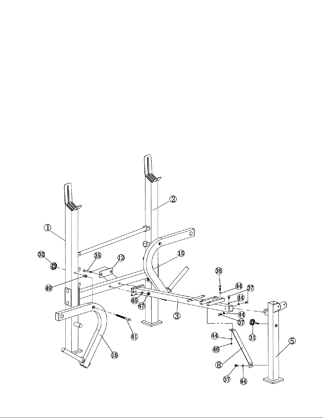
STEP 2 (See Diagram 2)
A.) Do not tighten Nuts and Bolts until instructed to do so.
B.) Attach Main Seat Support (#3) to the Cross Brace (#4). Secure it with a 4 3/8” x 3 3/8”
Bracket (#12), two M10 x 2 ½” Carriage Bolts (#35), two ∅ ¾” Washers (#45), and two
M10 Aircraft Nuts (#47).
C.) Attach the Front Post (#5) to the Main Seat Support. Secure it with three M8 x 5/8” Allen
Bolts (#37) and three ∅ 5/8” Washers (#44). Thread the M10 x 2 3/8” Lock Knob (#31)
into the Front Post.
D.) Attach the Diagonal Support (#8) to Main Seat Support. Secure it with one M8 x 2 1/8”
Allen Bolt (#38), two Ø 5/8” Washers (#44), and one M8 Aircraft Nut (#48).
E.) Attach the other end of Diagonal Support to Front Post. Secure it with one M8 x 5/8”
Allen Bolt (#37) and one ∅ 5/8” washer (#44).
F.) Insert a M10 x 5 1/8” Hex Bolt (#41) through the hole on a Butterfly (#15). Secure the
Bolt with a Long Hex Nut (#49). Insert the Bolt through the hole on the Right Upright
Beam (#1) and secure with a M10 Lock Knob (#32). Repeat the same step to install the
other Butterfly to Left Upright Beam (#2),
G.) Securely tighten all Nuts and Bolts installed in Step-1 and Step-2.
DIAGRAM 2
Loading ...
Loading ...
Loading ...