Loading ...
Loading ...
3
Installation
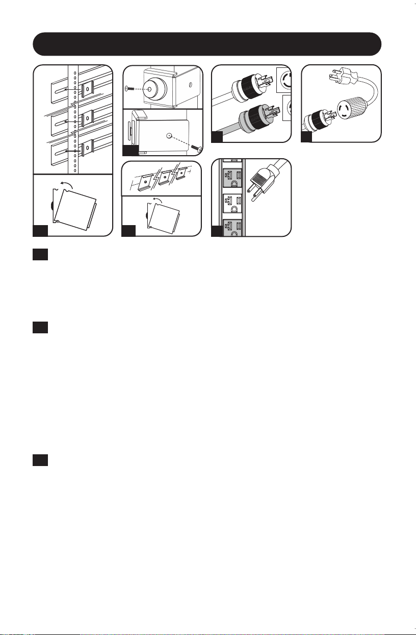
0U Rack Configuration (Mounting Clips). Attach the three mounting clips supplied with the
PDU to the rack enclosure using the included hardware. The mounting clips should be attached
along a vertical plane at equidistant points which approximately correspond to the center and
ends of the PDU. The exact mounting configuration may vary depending on the rack and
enclosure. If possible, use pre-existing mounting points within the enclosure. Using an assistant,
place a rear corner of the PDU at an inside edge of the mounting clips, pivot the PDU toward
the alternate inside edge and snap into place.
0U Rack Configuration (Mounting Buttons). To mount the PDU with the outlets facing
inward, align the mounting buttons on the rear of the PDU with the rack mounting slots and
slide the PDU into position. To mount the PDU with the outlets facing the rear of the rack
enclosure, remove and discard each of the screws that attach the mounting buttons to the
PDU*. Attach each mounting button to a mounting bracket using the included M3 screws,
and then attach each mounting bracket to the rear of the PDU (1 at the top, 1 at the middle,
and 1 at the base) using the included M4 screws (where the mounting button would
otherwise be placed). Position the PDU as desired in the rack enclosure, align the buttons
with the rack mounting slots, and slide the PDU into position.
* Three M3 screws are included with the mounting hardware and should be used to attach the mounting
buttons to the mounting brackets. The screw that was initially used to attach the mounting button to the
PDU should not be used to attach the mounting button to the mounting bracket or to attach the mounting
bracket to the PDU.
Wall or Under-Counter Configuration. Attach the three mounting clips supplied with the
PDU to a wall or similar flat, secure surface using the included hardware. The mounting clips
should be attached along a vertical or horizontal plane at equidistant points which
approximately correspond to the center and ends of the PDU. If possible, use pre-existing
mounting points. Using an assistant, place a rear corner of the PDU at an inside edge of the
mounting clips, pivot the PDU toward the alternate inside edge and snap into place.
WARNING: Do not attempt to mount the PDU with the outlets facing downward; the
mounting clips are not designed to support the weight of the PDU in that manner.
Note: Regardless of configuration, the user must determine the fitness of hardware and procedures before
mounting. The PDU and included hardware are designed for common rack and rack enclosure types and
may not be appropriate for all applications.
1C
2
3
4
1A
1A
1B
1B
1C
21-03-414-93364C.indb 321-03-414-93364C.indb 3 4/5/2021 12:47:06 PM4/5/2021 12:47:06 PM
Loading ...
Loading ...
Loading ...