Loading ...
Loading ...
Loading ...
5
ENGLISH
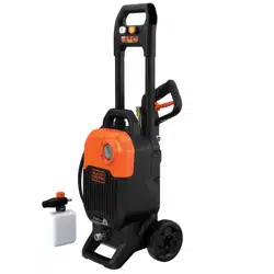
Attaching Nozzles (Fig.E)
DANGER: Risk of fluid injection. Do not direct
discharge stream toward persons, unprotected skin,
eyes or any pets or animals. Serious injury willoccur.
WARNING: Flying objects could cause risk of serious
injury. DO NOT attempt to change nozzles while
pressure washer is running. Turn pressure washer unit
OFF before changingnozzles.
1. To connect a nozzle to the spray wand
2
, pull the quick
connect collar
3
toward the spray wand and insert the
appropriatenozzle.
2. Release the quick connect collar to lock the nozzle inplace.
Attaching Garden Hose (Fig.D)
NOTE: Before connecting the garden hose to the pressure
washer unit, run water through the garden hose for thirty
seconds to clear any debris from inside thegardenhose.
1. To connect a garden hose to the
pressurewasherunit
8
,place the end of the
gardenhose
25
inside the water intake
11
.
2. Securely tighten the garden hose byhand.
NOTE: Always disconnect the garden hose afterusage.
Attaching High Pressure Hose (Fig.C)
NOTICE: Never pull high pressure hose or water supply
hose to move pressure washer. This could damage hose
and/or pumpinlet and/or pumpoutlet.
1. To connect the high pressure hose
1
to the
spray handle
4
, screw the hose collar
23
onto the
inlet coupler
24
.
2. To connect the high pressure hose to the pressure
washer unit
8
, screw the hose collar
23
onto the high
pressure water outlet
12
.
NOTE: Uncoil the high pressure hose before installation
to preventkinks.
NOTE: Avoid cross threading when installing the hose.
Cross threading will causeleaks.
Attaching Spray Handle (Fig.A, B)
1. To connect the spray wand
2
to the spray handle
4
,
insert the threaded end of the spray wand onto the
threaded end of the spray handle.
2. Rotate the spray handle clockwise until fullytightened.
3. Give the spray wand a firm tug after tightening to ensure
the spray wand is fullytightened.
ASSEMBLY AND ADJUSTMENTS
WARNING: To reduce the risk of serious personal
injury, turn unit off and disconnect it from
power source before making any adjustments or
removing/installing attachments or accessories.
An accidental start‑up can causeinjury.
Motor
Be sure your power supply agrees with the nameplate
marking. Voltage decrease of more than 10% will cause loss
of power and overheating. These tools are factory tested; if
this tool does not operate, check powersupply.
The label on your tool may include the following symbols. The
symbols and their definitions are asfollows:
V ......................... volts
Hz .......................hertz
min ..................... minutes
or DC ......direct current
...................... Class I Construction
(grounded)
…/min ..............per minute
BPM .................... beats per minute
IPM ..................... impacts per minute
OPM .................... oscillations per
minute
RPM .................... revolutions per
minute
sfpm ................... surface feet per
minute
SPM .................... strokes per minute
A ......................... amperes
W ........................watts
Wh ......................watt hours
Ah ....................... amp hours
or AC ...........alternating current
or AC/DC .... alternating or direct
current
...................... Class II Construction
(double insulated)
n
o
.......................no load speed
n .........................rated speed
PSI....................... pounds per square
inch
......................earthing terminal
.....................safety alert symbol
..................... visible radiation
do not stare into
the light
..................... wear respiratory
protection
..................... wear eye protection
..................... wear hearing
protection
..................... read all
documentation
ampere rating. If in doubt, use the next heavier gauge. The
lower the gauge number, the heavier thecord.
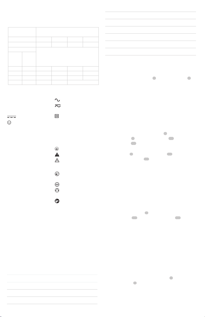
Minimum Gauge for Cord Sets
Volts
Total Length of Cord in Feet
(meters)
120 V 25 (7.6) 50 (15.2) 100 (30.5) 150 (45.7)
240 V 50 (15.2) 100 (30.5) 200 (61.0) 300 (91.4)
Ampere Rating
American Wire Gauge
More
Than
Not
More
Than
0 6 18 16 16 14
6 10 18 16 14 12
10 12 16 16 14 12
12 16 14 12 Not Recommended
Specifications
Maximum Pounds per Square Inch* 2000
Rated Gallons per Minute* 1.2
Electrical Requirements 120V
AC
~60Hz, 13A
Electrical Cord 35 ft. (10.6 m)
High Pressure Hose 25 ft. (7.6 m)
Minimum Amp Source 15A
Pressure of Inlet Water 20‑100 PSI
Inlet Water Cold Tap
Soap Consumption Rate 10% MAX
*Water flow and maximum pressure ratings determined in accordance with
CETA CPC‑100.
Loading ...
Loading ...
Loading ...