Models:
Indoor Unit Outdoor Unit
UMAT18HP230V1AD UMAT18HP230V1AO
UMAT24HP230V1AD UMAT24HP230V1AO
UMAT30HP230V1AD UMAT30HP230V1AO
UMAT36HP230V1AD UMAT36HP230V1AO
UMAT42HP230V1AD UMAT42HP230V1AO
UMAT48HP230V1AD UMAT48HP230V1AO
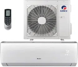
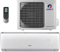
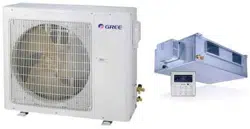
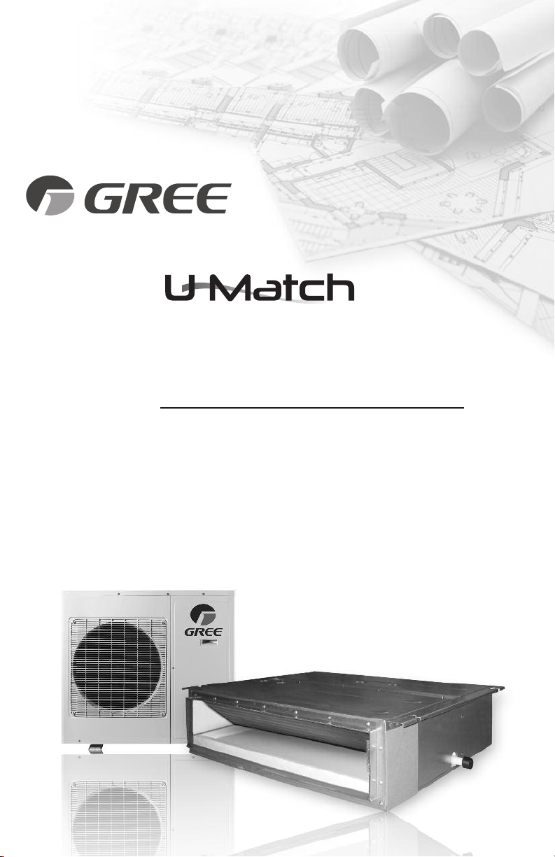
SLIM CONCEALED DUCT
AIR CONDITIONING & HEATING SYSTEM
INSTALLATION MANUAL

Thank you for choosing a
Slim Concealed Duct
unit for your customer.
Please read this installation manual carefully before installing and starting up the
U-Match System. Take a moment to fill out the product and installation form on the
back cover. Retain both the manual and installation record for future reference.
Table of Contents
Safety Precautions . . . . . . . . . . . . . . . . . . . . . . . . . . . . . . . . . . . . . . . . . . . . 2
Nomenclature . . . . . . . . . . . . . . . . . . . . . . . . . . . . . . . . . . . . . . . . . . . . . . . . 3
System Requirements . . . . . . . . . . . . . . . . . . . . . . . . . . . . . . . . . . . . . . . . . . 4
Suggested Tools . . . . . . . . . . . . . . . . . . . . . . . . . . . . . . . . . . . . . . . . . . . . . . 5
System
Schematic
.
. . . . . . . . . . . . . . . . . . . . . . . . . . . . . . . . . . . . . . . . . .
6
Standard Parts . . . . . . . . . . . . . . . . . . . . . . . . . . . . . . . . . . . . . . . . . . . . . . . . 7
Installation Site Instructions . . . . . . . . . . . . . . . . . . . . . . . . . . . . . . . . . . . 8 - 9
Indoor Unit Installation . . . . . . . . . . . . . . . . . . . . . . . . . . . . . . . . . . . . . 10-12
Outdoor Unit Installation . . . . . . . . . . . . . . . . . . . . . . . . . . . . . . . . . . . 13-14
Piping Installation . . . . . . . . . . . . . . . . . . . . . . . . . . . . . . . . . . . . . . . . . 15-19
Ductwork Installation . . . . . . . . . . . . . . . . . . . . . . . . . . . . . . . . . . . . . . 20-22
Power and Wiring Installation . . . . . . . . . . . . . . . . . . . . . . . . . . . . . . . 23-25
Controller Installation and setup . . . . . . . . . . . . . . . . . . . . . . . . . . . . . 26-27
Testing and Inspection . . . . . . . . . . . . . . . . . . . . . . . . . . . . . . . . . . . . . 28-30
Troubleshooting . . . . . . . . . . . . . . . . . . . . . . . . . . . . . . . . . . . . . . . . . . . 31-32
Diagnostic Codes . . . . . . . . . . . . . . . . . . . . . . . . . . . . . . . . . . . . . . . . . 33-36
Care and Cleaning . . . . . . . . . . . . . . . . . . . . . . . . . . . . . . . . . . . . . . . . . . . 37
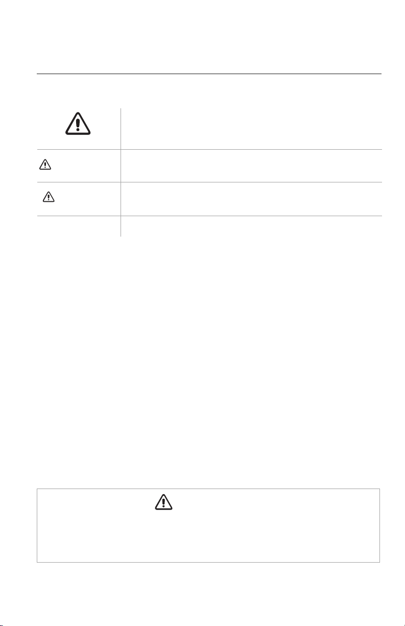
SAFETY PRECAUTIONS
Please read the following before installation.
This is the safety alert symbol. It is used to alert you to potential
personal injury hazards. Obey all safety messages that follow this
symbol to avoid possible injury or death.
This mark indicates procedures which, if improperly performed,
might lead to the death or serious injury of the user.
This mark indicates procedures which, if improperly performed, might
possibly result in personal harm to the user, or damage to property.
Notice is used to address practices not related to personal injury.
General Safety Precautions
1. Instructions for installation and use of this product are provided by the manufacturer.
For proper operation, the system must be installed in accordance with this
installation manual.
2. Installation must be performed in accordance with local laws, regulations and
National Electrical Codes (NEC).
3. If refrigerant leaks while work is being carried out, ventilate the area. Do not allow
refrigerant to come in contact with a flame as it produces toxic gas.
4. Disconnect all electrical power to the indoor and outdoor units until the system is
ready for start-up and checkout.
5. When installing or repairing the system, use only R410A refrigerant. Do not
mix refrigerant with other gases. If air or other gas enter the refrigeration system,
the pressure inside the system may rise to an abnormally high value and cause
damage or injury.
This appliance is not intended for use by persons (including children) with reduced physical,
sensory or mental capabilities, or lack of experience and knowledge, unless they have been given
supervision or instruction concerning use of the appliance by a person responsible for their safety.
WARNING
CAUTION
NOTICE
2
WARNING
3
Indoor unit
Outdoor unit
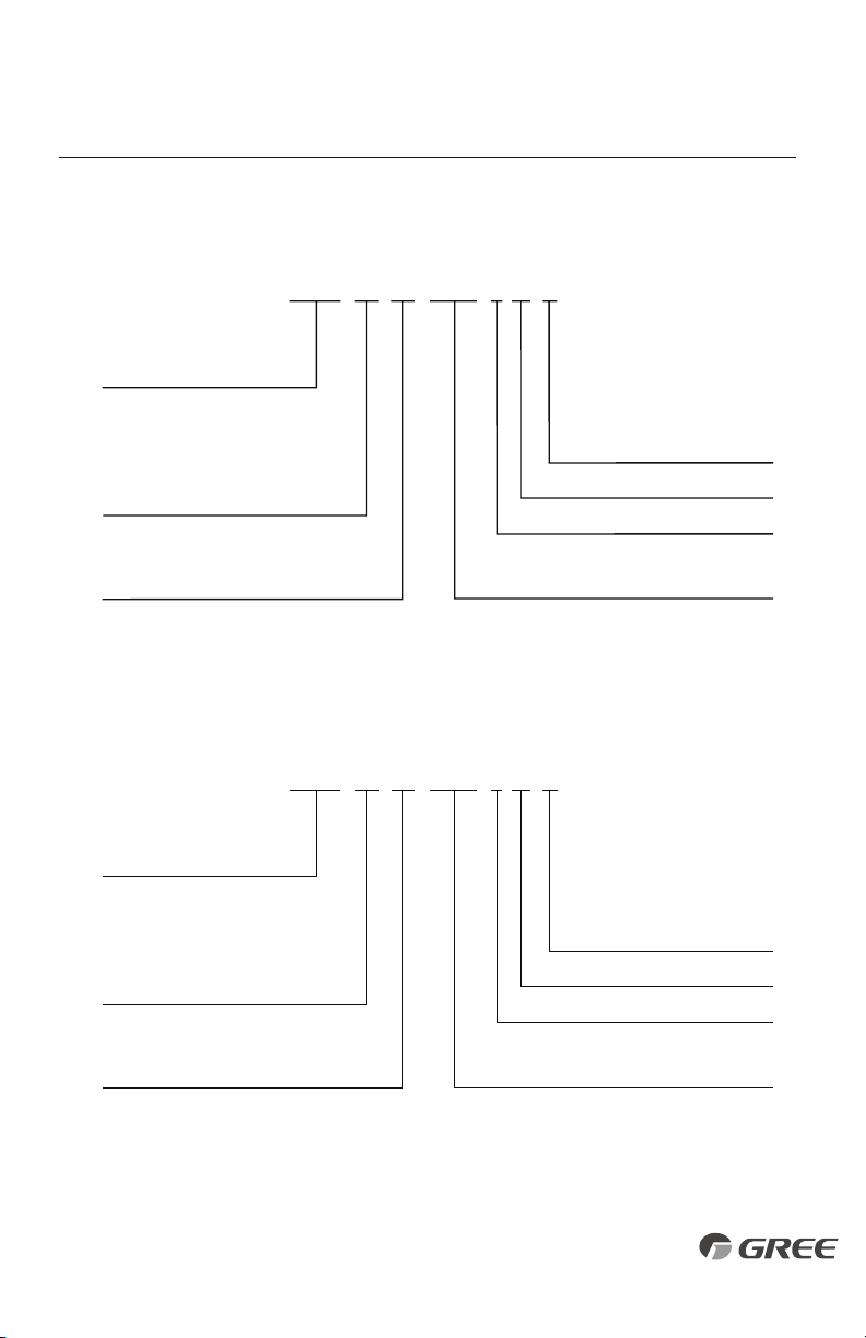
NOMENCLATURE
UMAT 18 1 A D
Series Designation
UMAT – U-Match Series
Product Type
S - System
O - Outdoor Units
H - Indoor High Wall
D - Indoor Duct
C - Indoor Cassette
F - Indoor Floor/Ceiling
Revision Level
Style/Color Designation
Electrical Rating
230V - 208/230V 60Hz 1PH
115V - 115V 60Hz 1PH
HP
230V
Cooling Capacity
18 - 18,000 BtuH
24 - 24,000 BtuH
30 - 30,000 BtuH
36 - 36,000 BtuH
42 - 42,000 BtuH
48 - 48,000 BtuH
Model Type
AC - Cooling Only
HP - Heat Pump
HC - Heat/Cool
Example: UMAT18HP230V1AD
UMAT 18 1 A O
Series Designation
UMAT – U-Match Series
Product Type
S - System
O - Outdoor Units
H - Indoor High Wall
D - Indoor Duct
C - Indoor Cassette
F - Indoor Floor/Ceiling
Revision Level
Style/Color Designation
Electrical Rating
230V - 208/230V 60Hz 1PH
115V - 115V 60Hz 1PH
HP
230V
Cooling Capacity
18 - 18,000 BtuH
24 - 24,000 BtuH
30 - 30,000 BtuH
36 - 36,000 BtuH
42 - 42,000 BtuH
48 - 48,000 BtuH
Model Type
AC - Cooling Only
HP - Heat Pump
HC - Heat/Cool
Example: UMAT18HP230V1AO
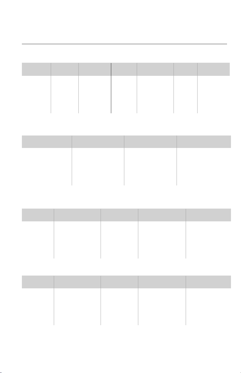
SYSTEM REQUIREMENTS
REFRIGERANT CHARGE
INDOOR UNIT ELECTRICAL REQUIREMENTS
PIPE SIZE in (mm)
Notes: Insulate both refrigerant lines, separately.
Communication Cable: Recommended cable - 18/2 AWG stranded bare copper conductors
300V unshielded wire
Note: Use shielded cable if installation is in close proximity of RF and EMI
transmitting devices.
Unit Size
(BtuH)
18,000 1/4 (6) 1/2 (12) 10 (3) 25(7.5)
164 (50)
49 (15)
24,000 3/8 (10) 5/8 (15) 10 (3) 25(7.5)
164 (50
)
49 (15)
30,000 3/8 (10) 5/8 (15) 10 (3) 25(7.5)
164 (50)
49 (15)
36,000 3/8 (10) 5/8 (15) 10 (3) 25(7.5)
164 (50
49 (15)
42,000 3/8 (10) 5/8 (15) 10 (3) 25(7.5)
164 (50)
98 (30)
48,000 3/8 (10) 5/8 (15) 10 (3) 25(7.5)
230 (70)
98 (30)
Min Line
Max. Pre-Charge
Max Line
Max Elevation
Length
Line Length
Length
(ID over OD)
Liquid Suction/Gas
Line Line
Unit Size Refrigerant Factory System Additional
(BtuH) Type Charge oz (kg)* Charge oz/ft (g/m)
18,000 R410A 49.4 (1.4) 0.3 (30)
24,000 R410A 78.4 (2.2) 0.6 (60)
30,000 R410A 84.6 (2.4) 0.6 (60)
36,000 R410A 123.2 (3.6) 0.6 (60)
42,000 R410A 131.2 (3.8) 0.6 (60)
48,000 R410A 141.8 (4.1) 0.6 (60)
Unit Size
Voltage
Min Circuit Max Overcurrent Main Power
(BtuH) Amps (MCA) Protection (MOCP) Wire Size (AWG)
18,000 208/230v - 1ph 60hz 1.0 15 14
24,000 208/230v - 1ph 60hz 2.0 15 14
30,000 208/230v - 1ph 60hz 2.0 15 14
36,000 208/230v - 1ph 60hz 3.0 15 14
42,000 208/230v - 1ph 60hz 3.0 15 14
48,000 208/230v - 1ph 60hz 5.0 15 14
OUTDOOR UNIT ELECTRICAL REQUIREMENTS
Unit Size
Voltage
Min Circuit Max Overcurrent Main Power
(BtuH) Amps (MCA) Protection (MOCP) Wire Size (AWG)
18,000 208/230v - 1ph 60hz
15.9
25 10
24,000 208/230v - 1ph 60hz
23.4
40 10
30,000 208/230v - 1ph 60hz
23.4
40 10
36,000 208/230v - 1ph 60hz
27.7
45 8
42,000 208/230v - 1ph 60hz
29.7
50 8
48,000 208/230v - 1ph 60hz
36.5
70 6
*Precharge amount for up to 25-ft of refrigerant pipe.
REFRIGERANT LINE LENGTHS ft (m)
4
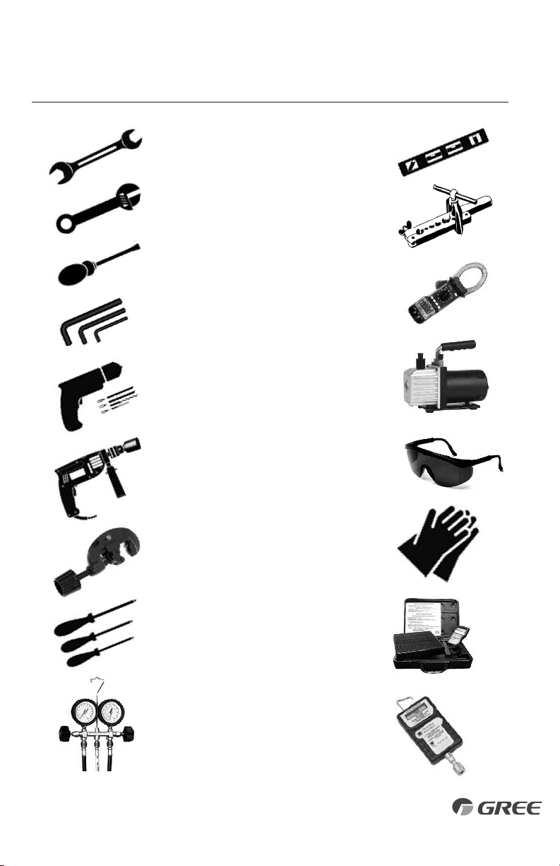
• Standard Wrench
• Adjustable/Crescent Wrench
• Torque Wrench
• Hex Keys or Allen Wrenches
• Drill & Drill Bits
• Hole Saw
• Pipe Cutter
• Screw drivers (Phillips & Flat blade)
• Manifold and Gauges
• Level
• R410A Flaring Tool
• Clamp on Amp Meter
• Vacuum Pump
• Safety Glasses
• Work Gloves
• Refrigerant Scale
• Micron Gauge
SUGGESTED TOOLS
5
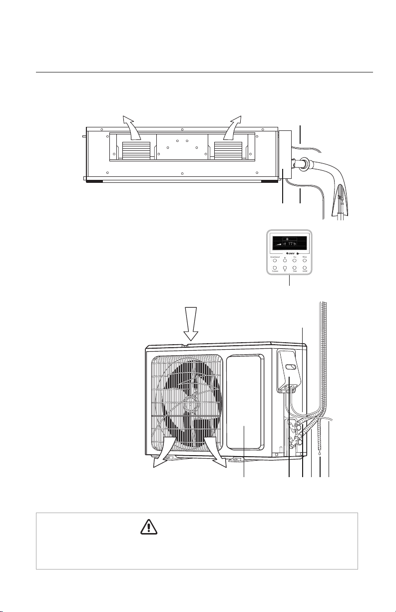
SYSTEM SCHEMATIC
Indoor Unit
System Components*
1.Indoor Power Supply
2.Electric Box
3.Communication Cable
4.XK60 Wired Programmable Controller
5.Communication Cable
6.Front Panel
7.Service Cover
8.Liquid Pipe
9.Gas Pipe
10.Drain Hose
11.Outdoor Power Supply
Outdoor Unit
3
1
Air outlet
Air outlet
Air inlet
2
10
9
87
11
6
The refrigerant pipe, drain pipe, electrical wiring, and duct for this unit should be installed
by a qualified HVAC professional only.
6
4
CAUTION
5
* Not all components included
with equipment purchase.
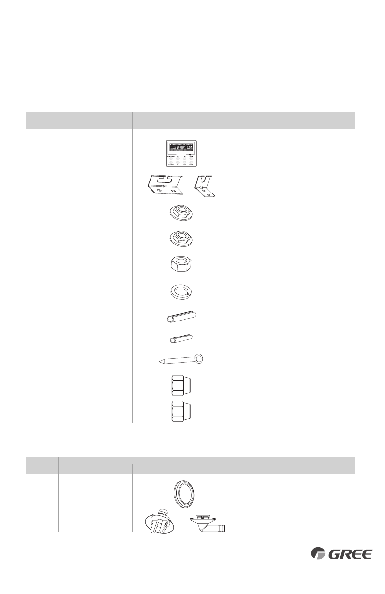
STANDARD PARTS
Indoor Unit Accessories
Outdoor Unit Accessories
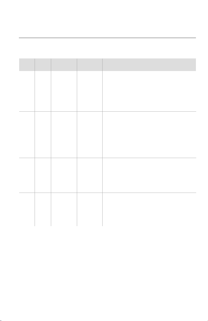
No. Name Appearance Qty Usage
1 Wired Controller 1 Controls the indoor unit
2 Hanger or 4 Supports the indoor unit
3 Nut with Washer 8 Fastens the hanger brackets
to the cabinet of the unit
4 Nut with Washer 4 Fastens the hanger brackets
to the cabinet of the unit
5 Nut 4 Used with the suspension
bolt for installing the unit
6 Washer 4 Used with the suspension
bolt for installing the unit
7 Pipe Insulation 1 Insulates the gas pipe
8 Pipe Insulation 1 Insulates the liquid pipe
9 Fastener 4
Fastens the insulation blanket
10 Flare Nut 1 Connects the liquid pipe
11 Flare Nut 1 Connects the gas pipe
7
No. Name Appearance Qty Usage
1 Drain Plug 2 or 3 Plugs the unused drain hole
2 Drainage Connecter
or
1
Connects with the hard
PVC drain pipe
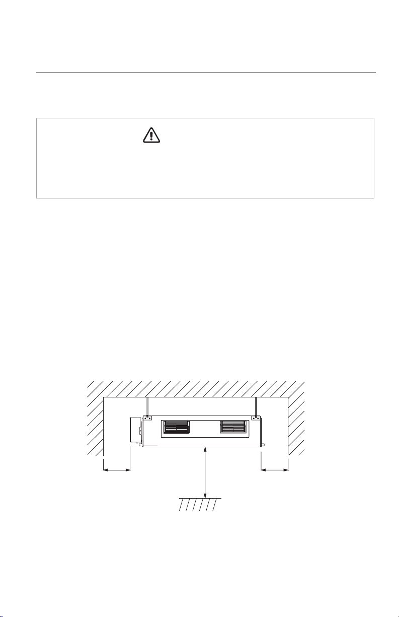
INSTALLATION SITE INSTRUCTIONS
Indoor Unit
The unit must be installed in a location which can withstand twice the weight of the unit.
Inadequate building support at the installation location may result in serious property
damage and injuries.
Review the installation location with the customer as follows:
1. Ceiling is strong enough to support twice the weight of the unit.
2. Ductwork can easily be installed using the shortest amount of duct.
3. Location allows easy installation of drain pipe.
4. Electrical power can easily be run as a dedicated circuit.
5. Space is left around the unit as required in Fig. 1.1 for future service and maintenance.
6. Air inlet and outlet of the unit should never be blocked, so airflow can reach every
corner of the room.
8
WARNING
Fig. 1.1
>12 in.
>72 in.
>12 in.
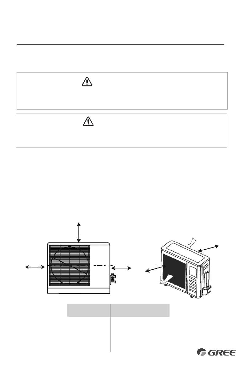
INSTALLATION SITE INSTRUCTIONS
Outdoor Unit
9
Do not install the unit at a location where the distance exceeds the maximum length indicated in
the table. The maximum length of the connection pipe is listed in the System Requirements section.
CAUTION
WARNING
Outdoor Unit
Minimum Distances
in (mm)
A 20 (500)
B 20 (500)
C 24 (610)
D 12 (305)
E 12 (305)
Air inlet
Air outlet
A
B
C D
E
Fig. 1.2
The unit should be installed level on a pad that can support twice the weight of the unit.
If the outdoor unit will be exposed to strong winds, it must be adequately secured.
1. Install the outdoor unit at a location that is capable of withstanding twice the weight of the unit.
2. Install the outdoor unit where it is convenient to connect refrigerant lines to the indoor unit.
3. I nstall the outdoor unit where the condensate water can be drained unobstructed during the
heating mode to a safe location.
4. Do not locate the unit where the noise may be objectionable to neighbors.
5. Provide the space shown in Fig. 1.2, so that the air flow is not blocked and future service and
maintenance can be performed.
For the units: 18K
For the units: 24-42K
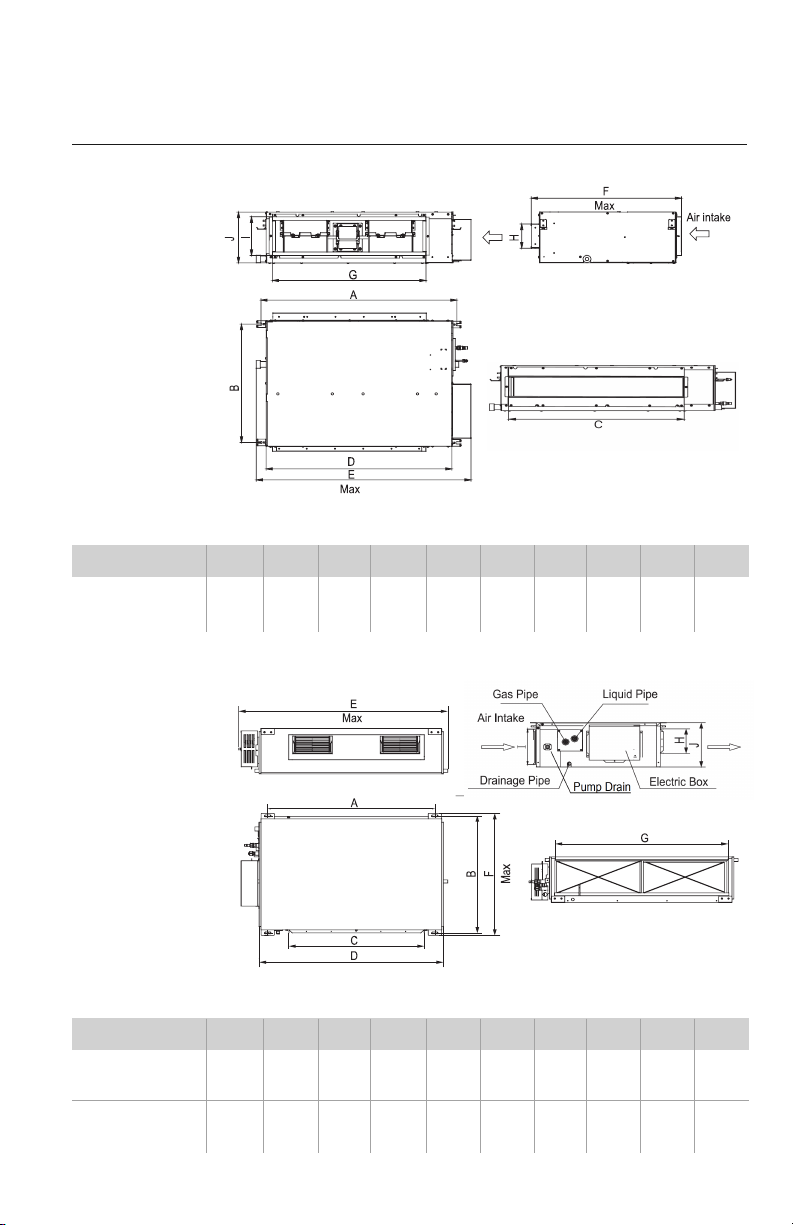
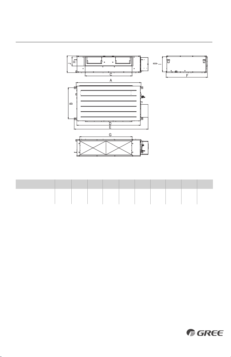
INDOOR UNIT INSTALLATION
10
Model ABCD EFGH I J
UMAT24HP230V1AD 43-3/8 20-3/8 32-1/4 45-5/8 50-3/8 22 39-1/2 6-1/4 9-1/4 10-1/2
UMAT30HP230V1AD (1101) (517) (820) (1159) (1279) (558) (1002) (160) (235) (268)
UMAT36HP230V1AD 39-3/4 29-1/2 32-1/4 43-7/8 48-1/4 30-1/2 38-1/2 6-1/4 9-1/8 11-3/8
UMAT42HP230V1AD (1010) (748) (820) (1115) (1226) (775) (979) (160) (231) (290)
INDOOR UNIT DIMENSIONS in (mm)
Model ABCD EFGH I J
UMAT18HP230V1AD
37-1/4 24-3/8 29 35-1/8 40-7/8 28-3/8 29 4-7/8 8 10-1/2
(945) (618) (738) (892) (1037) (721) (738) (125) (203) (266)
INDOOR UNIT DIMENSIONS in (mm)
(Approx)
For the units: 48K
INDOOR UNIT INSTALLATION
11
Model ABCD EFGH I J
UMAT48HP230V1AD
43-3/8 25-3/8 33-1/2 45-1/4 52-3/4 29-1/2 37-1/2 7-1/2 12-1/2 13-3/4
(1101) (646) (852) (1150) (1340) (750) (953) (190) (316) (350)
INDOOR UNIT DIMENSIONS in (mm)
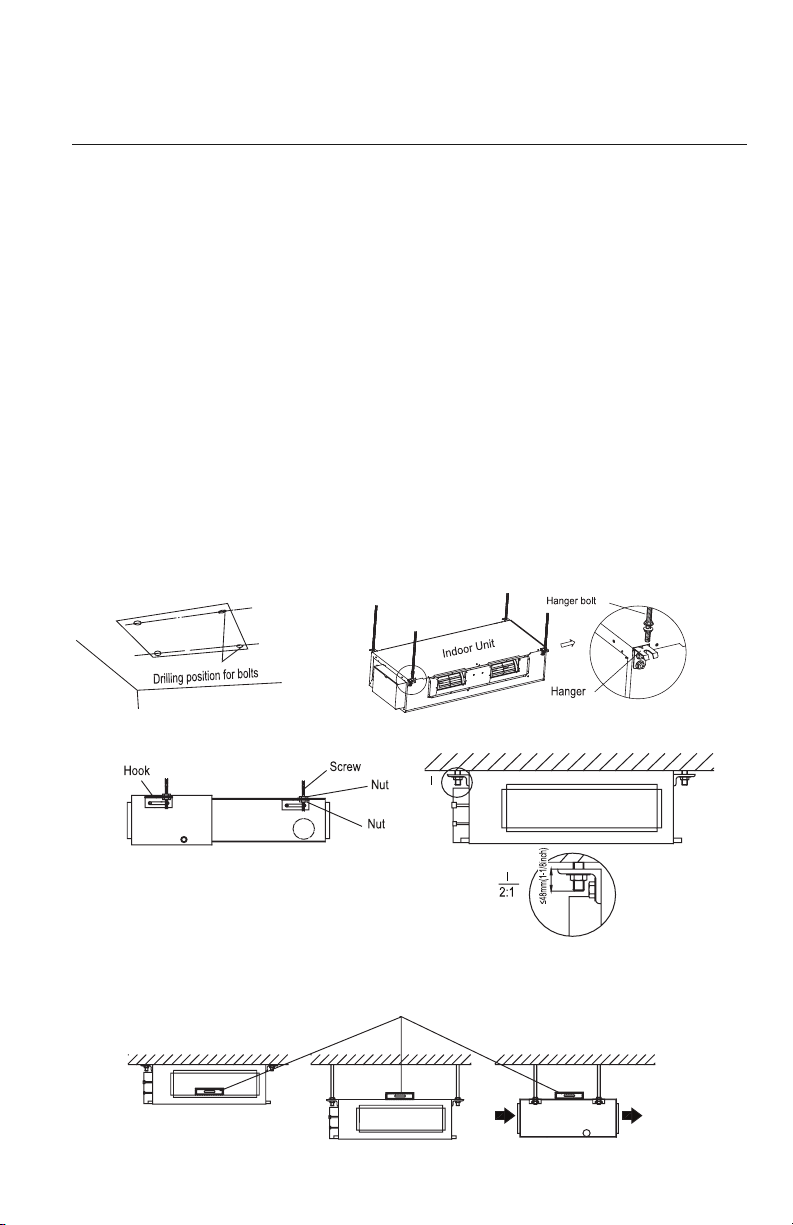
INDOOR UNIT INSTALLATION
Mounting Indoor Unit
It is critical to properly secure the indoor unit to a stable and rigid structure that can support twice
its weight for safety and product reliability.
Select the proper size suspension bolts or anchoring devices (field supplied) to support twice the
weight of the unit.
1. Locate a structure strong enough to support twice the weight of the unit.
2. Using the installation template supplied with the unit, mark the hole locations as shown in fig 2.1.
3. Drill 4 mounting holes for suspension bolts per the manufacturer's instructions.
4. Install 4 suspension bolts into pre-drilled holes.
5. Install the 4 hanger brackets to unit as shown in fig 2.2.
6 Add an upper nut to each suspension bolt.
7. Carefully lift unit and position the 4 hanger brackets on the suspension bolts.
8. Install a lower washer and nut to each suspension bolt to secure unit as shown in fig 2.3.
9. Adjust the unit height to desired position.
Leveling
After the indoor unit is installed and adjusted to proper height, check the unit position to ensure that the
unit is level as shown below.
12
Fig. 2.1 Fig. 2.2
Fig. 2.4
Fig. 2.3
Level Bar
13
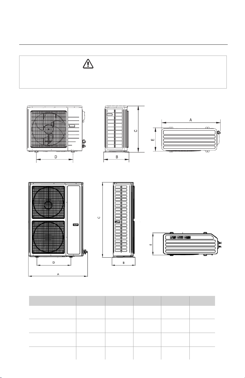
OUTDOOR UNIT INSTALLATION
The unit should be located with the unit support feet firmly on the equipment pad.
If the outdoor unit is exposed to wind, it must be properly secured.
WARNING
Model ABCDE
UMAT18HP230V1AO
37-5/8 15-5/8 27-1/2 22 14-1/8
(955) (396) (700) (560) (360)
UMAT24HP230V1AO 38-5/8 16-3/4 31-1/8 24 15-1/2
UMAT30HP230V1AO (980) (427) (790) (610) (395)
UMAT36HP230V1AO 43-5/8 17-3/8 43-1/4 24-7/8 15-3/4
UMAT42HP230V1AO (1107) (440) (1100) (631) (400)
UMAT48HP230V1AO
37-3/4 16-1/4 53-1/8 22-1/2 14-3/4
(958) (412) (1349) (572) (376)
OUTDOOR UNIT DIMENSIONS in (mm)
18K-36K
42K-48K
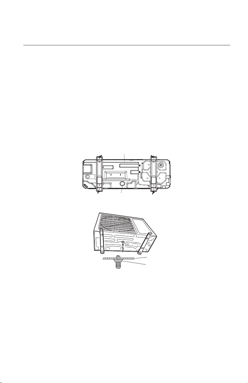
OUTDOOR UNIT INSTALLATION
Drain Joint
Chassis
Bottom
Drain pipe mounting hole
Condensate Drainage of the Outdoor Unit
The outdoor unit should be installed with a drain pipe to drain condensate water during the
heating mode.
1. Insert the drain joint (included) into the selected hole located on the bottom of the
base pan and then connect the drain hose (field supplied) to the drain joint.
2. All other holes must be sealed with plugs (included) to avoid water leaks, except for
the drain pipe mounting hole.
3. Route drain hose to safe location for disposing of condensate water.
14
Piping Preparation
1. Do not open service valves or remove protective caps on pipes until instructed by this manual.
2. Keep tubing free of dirt, sand, moisture and contaminants.
3. Insulate each refrigerant pipe and condensate hose with minimum 3/8” (10 mm) wall
thermal pipe insulation.
4. Bind refrigerant pipes and interconnecting cable together with cable ties at 12-inch intervals.
5. Include the condensate hose in bundle for exterior portion only.
15
PIPING INSTALLATION
Refrigerant Piping
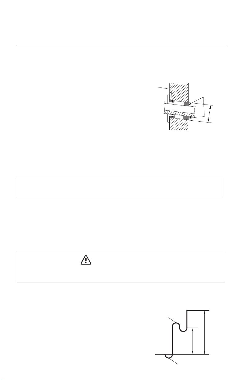
Drill Hole in Wall
1.
Locate and mark proper location for the wall hole.
2.
Cut the 2 3/4” wall hole with a 5° to 10°
downward slant to the outdoors.
3. Insert a wall sleeve (field supplied) into hole to
to prevent damage to refrigerant pipes, insulation,
condensate drain hose and wiring.
4. Proper weather proofing of the wall surface and
wall sleeve is essential to assure a trouble-free
installation. Apply sealant, caulking or equivalent weather proofing material around
the perimeter of the wall sleeve (interior & exterior) to eliminate outdoor air and water
leaks into the living space.
NOTE: Expandable foam insulation may be added to fill large wall gaps. Apply per
manufacturer's instructions.
Seal Hole
Hole Size
Indoor
Outdoor
Wall Hole Diagram
Oil return bend
Indoor
Outdoor
20 ft.
30 ft.
Oil return bend
Indoor Unit below Outdoor Unit Application
When height difference between indoor unit and outdoor
unit is more than 30 feet, an oil return bend should be added
for every 20 feet of connection pipe as shown.
Wall
Hole Sleeve
Insulate entire interior section of condensate hose to prevent sweating which may cause water
stains or wall damage.
CAUTION
16
PIPING INSTALLATION
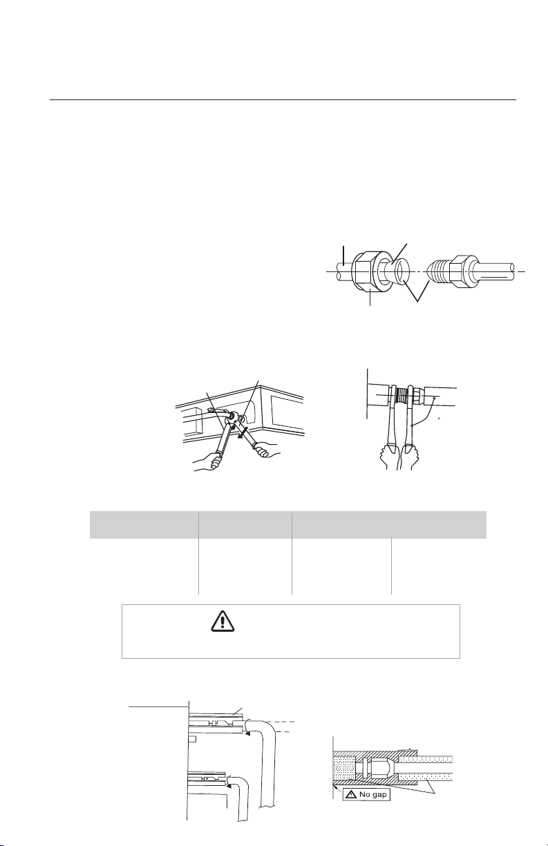
Indoor Unit Pipe Connections
1. Feed refrigerant pipes, drain hose and interconnecting wires assembly through wall hole
from outdoor to the indoor unit.
2. Pull the piping assembly to the unit. Carefully bend refrigerant pipes to meet indoor unit
connection ports. Use proper tools to avoid kinks.
3. Add a small amount of refrigerant oil to
both ends of the flare fittings.
4. Starting with either refrigerant pipe, carefully
center the pipe to the indoor unit connection
port then hand tighten the flare nut.
5. Repeat procedure with remaining pipe.
6. Tighten both flare nuts using a standard wrench and a torque wrench as shown below.
7. Carefully tighten flare nuts to correct torque level referring to the Torque Table below.
8. Individually insulate each bare refrigerant pipe and joint as shown below to prevent sweating.
Pipe Diameter Nut Size
Tightening Torque
inch (mm) inch (mm) ft-lbs N-m
1/4 (6.35) 1/4 (17) 10 to 13 14 to 18
3/8 (9.5) 3/8 (22) 25 to 30 34 to 42
1/2 (12.7) 1/2 (25) 36 to 45 49 to 61
5/8 (15.9) 5/8 (29) 50 to 60 68 to 82
Liquid pipe
Gas pipe
Front outlet
Insulate pipe connection
Insulate pipe
Reference A:
Cover this portion with insulation
Pipe insulation
Over tightening may damage flare connections and cause leaks.
CAUTION
Copper
piping
Oil applied
(to reduce friction
with the flare nut)
Flare nut
Oil applied
(improves seal
air-tightness)
90
90
Holding spanner
Torque wrench
PIPING INSTALLATION
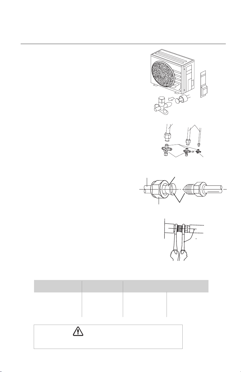
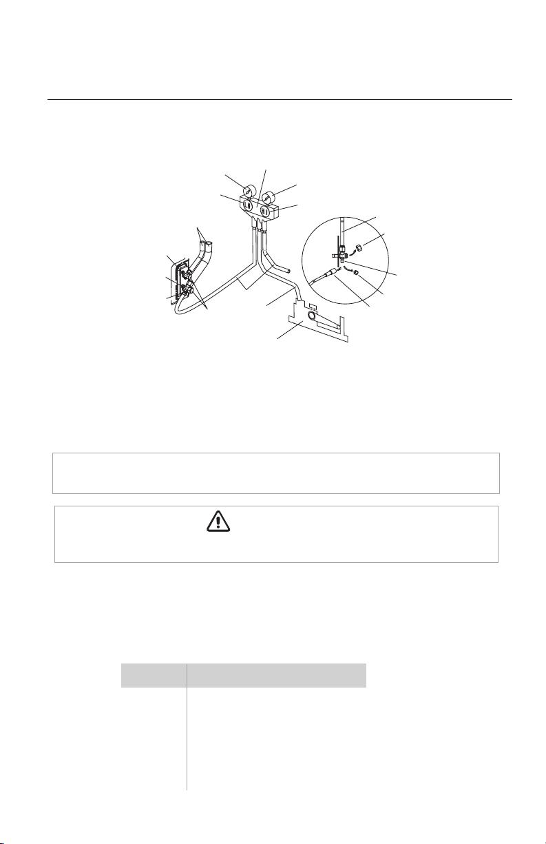
Outdoor Unit Pipe Connections
17
1. Remove service valve cover (if provided) to access
the service valves and refrigerant ports.
2. Carefully bend and adjust length of refrigerant pipes
to meet outdoor unit service valve connections
with proper tools to avoid kinks.
3. Add a small amount of refrigerant oil to both ends
of the flare fittings.
4. Starting with either refrigerant pipe, carefully
center the pipe to the indoor unit connection
port then hand tighten the flare nut.
5. Repeat procedure with remaining pipe.
6.
Tighten both flare nuts using a standard wrench
and a torque wrench as shown.
7. Carefully tighten flare nuts to correct torque level referring to the Torque Table below.
Pipe Diameter Nut Size
Tightening Torque
inch (mm) inch (mm) ft-lbs N-m
1/4 (6.35) 1/4 (17) 10 to 13 14 to 18
3/8 (9.5) 3/8 (22) 25 to 30 34 to 42
1/2 (12.7) 1/2 (25) 36 to 45 49 to 61
5/8 (15.9) 5/8 (29) 50 to 60 68 to 82
Copper
piping
Oil applied
(to reduce friction
with the flare nut)
Flare nut
Oil applied
(improves seal
air-tightness)
Over tightening may damage flare connections and cause leaks.
CAUTION
Gas pipe
3-way valve
R
2-way valve
Liquid pipe
or
Pipe
coupling
Service
Valve Cover
Service
Valve Cover
90
18
PIPING INSTALLATION
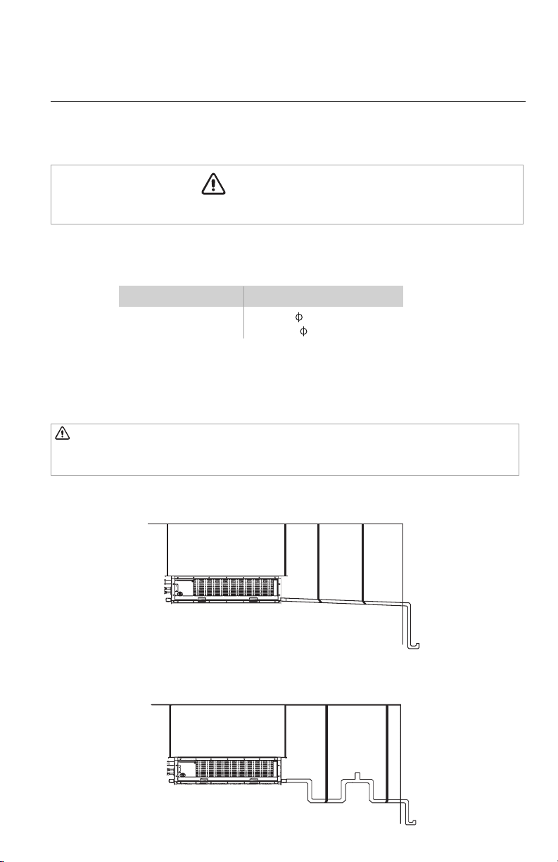
Indoor Condensate Drain Piping
Observe all local sanitary codes when installing condensate drains.
WARNING
See Table below for Condensate Drainage port size.
Pitch the condensate drain pipe at a gradual 2.5% pitch (Example: ¼-in drop over a 10-in length)
without obstructions. Use pipe hanger/brackets to support the condensate drain pipe from dropping.
NOTE: Insulate entire interior section of condensate hose and/or pipes to prevent sweating
which may cause water stains or wall damage.
Gravity Drainage System with P-Trap and Vent
Typical Gravity Drainage System
Capacity Size (BtuH) Drain Connection Size
(OD)
18,000 1-1/8 (30)
24,000-48,000 3/4 (20)
Ceiling
Hangers
Wall
Ceiling
Hangers
Trap
Vent
Wall
CAUTION When utilyzing gravity condensate drainage, the internal lift condensate
pump must be disconnected and its wiring insulated to prevent shorting. All unused
condensate drain ports must be plugged to prevent leakage.
19
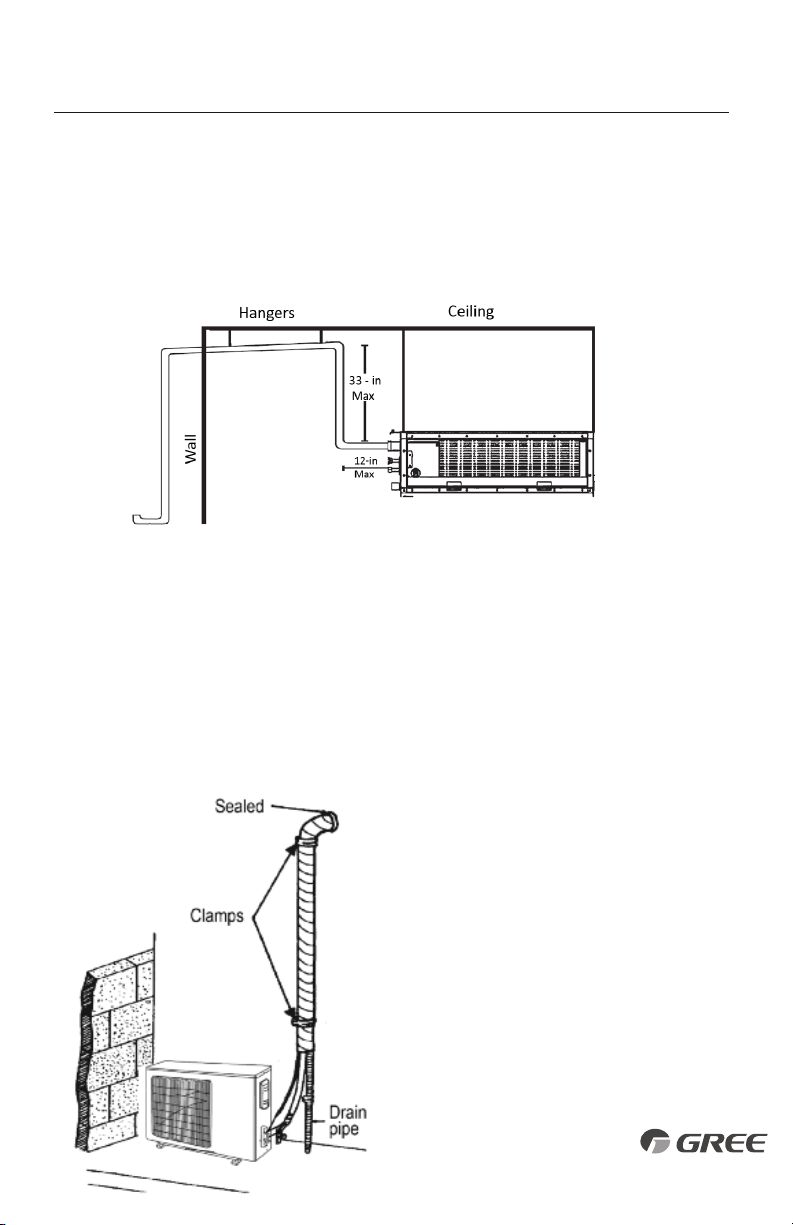
PIPING INSTALLATION
Vertical Lift Drainage System (Internal Condensate Pump)
If a gradual pitch from the drainage port is not obtainable, the indoor unit has a lift condensate
drain pump
*
with limited head or lift. The condensate drain pipe may have a vertical height of
33 in.
maximum above the unit drainage port within the first 12-in as long as the remaining
condensate
drain pipe gradually descends from that point and is aligned with drainage port.
Use an auxiliary condensate pump with float valve for vertical height greater than 33 in.
above the
unit drainage port. A float valve is recommended to shut off the system if the auxiliary pump fails.
The unit has two gravity drain ports and a factory installed condensate pump with an outlet port.
The condensate pump port must be utilized for condensate removal or the pump may be
disconnected from the control board if a gravity drain port is desired. If disconnected the
condensate pump plug must be electrically insulated to prevent an accidental short circuit. Use
piping of the same diameter or larger as the unit connection. Local code should be referenced for
approved condensate piping for your area.
• Include the condensate hose in the pipe/
wire bundle
for the exterior/outdoor
section.
• Fasten the refrigerant and condensate pipe
assembly
to the exterior wall for support.
• The drain pipe should terminate 6 inches
above grade.
20
The ductwork configuration should be based on the conditions of the building and maintenance
etc., as shown below.
DUCTWORK INSTALLATION
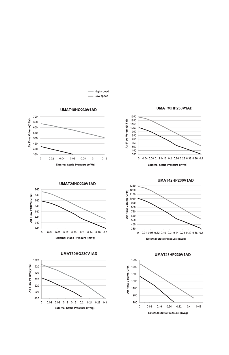
Design and Layout of Ductwork
Indoor Fan Performance
21
DUCTWORK INSTALLATION
Duct Sizing Suggestions
Correct ductwork design is critical to insure proper system performance. The total length of the ductwork
is the length of the return air duct plus the supply air duct. It is recommend that the ductwork and
register selection should follow ACCA manual D duct design to insure proper velocity and air flow.
Capacity Size (BtuH) 18K 24K 30K 36K 42K 48K
Air Flow Rate (CFM) 585 820 820 1175 1175 1470
Ext. Static Pressure (InWg) 0.1 0.1 0.15 0.15 0.15 0.2
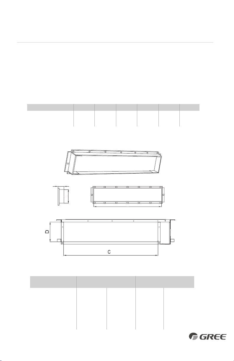
Model
Supply Air Outlet Return Air Inlet
ABCD
UMAT18HP230V1AD 4-7/8 (123) 29 (736) 28 (710) 6-1/2 (166)
UMAT24HP230V1AD 6-1/4 (158) 32-1/4 (818) 39-1/8 (994) 7-5/8 (195)
UMAT30HP230V1AD 6-1/4 (158) 32-1/4 (818) 39-1/8 (994) 7-5/8 (195)
UMAT36HP230V1AD 6-1/4 (158) 32-1/4 (818) 39-3/8 (1000) 8-1/8 (206)
UMAT42HP230V1AD 6-1/4 (158) 32-1/4 (818) 39-3/8 (1000) 8-1/8 (206)
UMAT48HP230V1AD 7-1/2 (190) 33-1/2 (850) 37 (940) 11-1/4 (286)
SUPPLY AIR OUTLET/RETURN AIR INLET DIMENSIONS in (mm)
NOMINAL EXT. STATIC PRESSURE
B
21mm(7/8inch)
A
Duct Connection Requirements
Side View
Supply Air Outlet
Return Air Intlet
3
2
6
5
4
Supply air
Return air
1
3
4
6
5
Supply air
Return air
R
Part Name
1. Return Air Inlet (with filter)
2. Canvas Duct
3. Return Air Duct
4. Indoor Unit
5. Supply Air Duct
6. Return Air Cover Plate(18K only)
18K only
22
DUCTWORK INSTALLATION
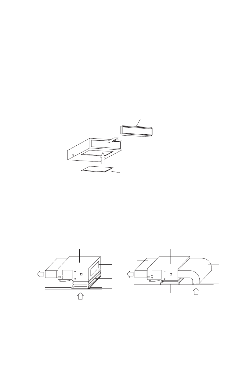
Bottom Return Air Installation (18,000 BtuH Only)
The 18,000 BtuH size duct can be converted from a rear to bottom side return. More noise is produced
with the bottom return air location than the rear return air, so it is suggested to provide a duct silencer
to minimize the noise. The default location of the return air connection is at the rear.
If the bottom return air connection is desired, switch the location of the rectangular flange and the
return air cover plate as shown below:
1. Connect return air duct (#3) to the return air inlet of the unit (#4) and the other end to a return
air register. Ensure return ductwork is properly supported with hangers.
2. Connect supply air duct (#5) to the supply air outlet of the unit (#4) and the other end to a
discharge air register. Ensure supply ductwork is properly supported with hangers.
Return Air Cover Plate
Bottom Return Air
Rear Return Air
Rectangular Flange
Attaching Ductwork to Indoor Unit
POWER AND WIRING INSTALLATION
WARNING
1. Before obtaining access to terminals, all electrical supply circuits must be disconnected.
2. Always use an independent circuit and provide an independent circuit breaker to supply
power to the system.
3. Use a circuit breaker with adequate capacity to meet the requirements of the total system.
4. A circuit breaker or fuse should be installed per the National Electric Code (NEC) and
local regulations.
5. Electrical wiring must be completed in accordance with NEC, local laws, and regulations
of the electric company so that the system will operate properly.
6. Provide a GFI circuit breaker at the electrical panel in accordance with the NEC and the
local electrical company standards.
7. Connect the connection wires firmly to the terminal block. Improper installation may
cause a fire.
CAUTION
1.The main power supplies and fresh air damper are high-voltage, while the
communication
wire and the Programmable Controller are low-voltage. They should be
installed separately to avoid electromagnetic interference.
2.
High-voltage and low-voltage lines should pass through separate rubber rings at electric
box covers.
3.If the indoor unit communication wire (to the outdoor unit) and power wire are
connected incorrectly, the air conditioner may be damaged.
4.
Ground both indoor unit and outdoor unit to earth ground in accordance with the
applicable
local and national codes.
23
24
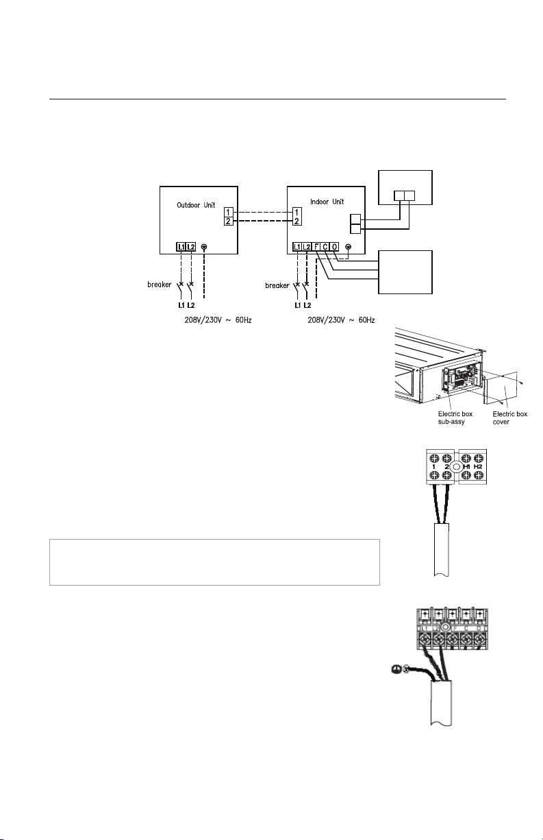
Electric Wiring Between Indoor Unit and Outdoor Unit
Single-phase units
(18K~48K)
POWER AND WIRING INSTALLATION
G
Power: Power:
Outdoor
Air Damper
Wired
Controller
H1H1
H2H2
G
X1X1 XX22
Indoor Unit Electrical Wiring
Locate and remove the electrical box cover to access wire terminals.
Indoor Communication Wiring
The recommended communication cable size is a minimum 18/2
AWG
stranded bare copper conductors 300V unshielded wire. Use
shielded cable if installation is in close proximity of RF and EMI
transmitting devices.
Locate wire terminals #1 and #2. Connect
communication cable from
outdoor unit to terminals #1 and #2.
Secure cable inside wire clamp/strain
relief. Verify cable is secure,
not loose and no external force on wires affects the connections at
the terminals.
Indoor Unit Power Wiring
Locate wire terminals L1 and L2. Connect main electrical power
outdoor unit to terminals L1 and L2. Connect ground wire to
grounding screw. Secure electrical wires inside wire clamp/strain
relief. Verify wires are secure, not loose and no external force on
wires affects the connections at the terminals.
Programmable
Controller Wiring
Use a minimum 18-2 AWG wire (field supplied) to connect Programmable Controller to
the indoor
unit. Route wire from Programmable Controller into electrical box. Locate wire
terminals H1
and H2.
Connect Programmable Controller wires to H1and H2. Verify wires
are secure, not loose and no external force on wires affects the connections at the
terminals.
NOTE: Record wire colors and terminal references for use
with Outdoor Unit wire connections.
Typical Wiring Diagram
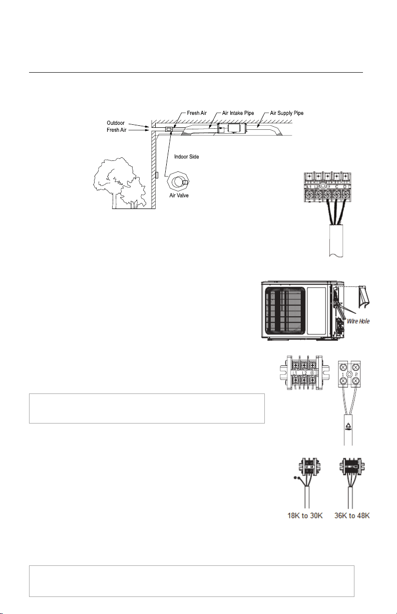
Outdoor Air Damper Wiring (optional)
Outdoor Unit Electrical Wiring
Remove the large handle access plate on the 18K to 30K size or
the front panel for the 36K to 48K size to access wire terminals.
POWER AND WIRING INSTALLATION
Outdoor Unit Power Wiring
Insert main power wires through the wire holes on conduit mounting bracket.
Secure main electrical power conduit with locking nuts to conduit mounting
bracket. Locate wire terminals L1 and L2. Adjust wire lengths for proper
connections to the outdoor unit terminal block. Connect main electrical
power outdoor unit to terminals L1 and L2. Connect Ground wire to ground terminal/screw. Secure
electrical wires inside wire clamp/strain relief. Verify wires are secure, not loose and no external force on
wires affects the connections at the terminals. Replace and secure electrical box cover to outdoor unit.
NOTE: Crossing communication wires will cause an E6 system
malfunction code and possible damage.
Outdoor Communication Wiring
Connect communication cable from indoor unit to terminals
#1 and #2. Maintain the same wire colors and terminal references
as indoor unit wire connections.
Secure cable inside wire clamp/strain relief. Verify cable is secure, not loose
and no external force on wires affects the connections at the terminals.
Follow the manufacturer’s instructions for installing and wiring the outdoor air
damper. On the indoor unit, locate wire terminals F, C, O for outdoor air damper.
Make necessary connections to F (Common), C (Close) and O (Open) terminals.
Secure electrical wires inside wire clamp/strain relief. Verify wires are secure, not
loose and no external force on wires affects the connections at the terminals.
NOTE: When connecting the power wire, make sure that the phase of the power supply matches
with the exact terminal board. If not, the compressor will rotate reversely and run improperly.
25
26
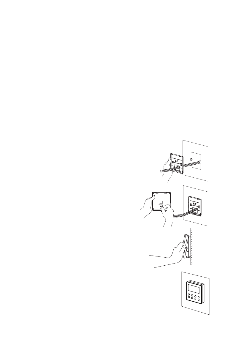
CONTROLLER INSTALLATION AND SETUP
Wired Programmable Controller
Installation
Pull communication cable through switch box (if one is
used) and Wired Programmable Controller backplate.
Securely fasten backplate to the switch box or wall.
Locate wire terminals X1 and X2 on rear of
Programmable Controller panel. Carefully connect wire
X1 to indoor unit terminal H1 and X2 to indoor unit
terminal H2. Verify wires are secure, not loose and no
external force on wires affects the connections at the
terminals.
Push extra cable into wall and secure
controller panel to backplate mounted on the wall.
NOTE: Do not cut or splice communication cable.
Follow the instructions supplied with the Owner's
Manual
for setup and operation.
The following is a brief overview of the Wired Programmable Controller installation. See Owner's
Manual for
more detailed instructions for setup and operation.
Preparation for Installation
Select a proper location on the wall for mounting the Programmable Controller. Install switch box,
if required by code. The maximum wire length between indoor and Programmable Controller is 30-ft.
Run communication cable (as desired) between indoor unit and selected wall mounting
location. See Indoor Unit wiring section for instruction to connect the Wired Programmable Controller
to the indoor unit.
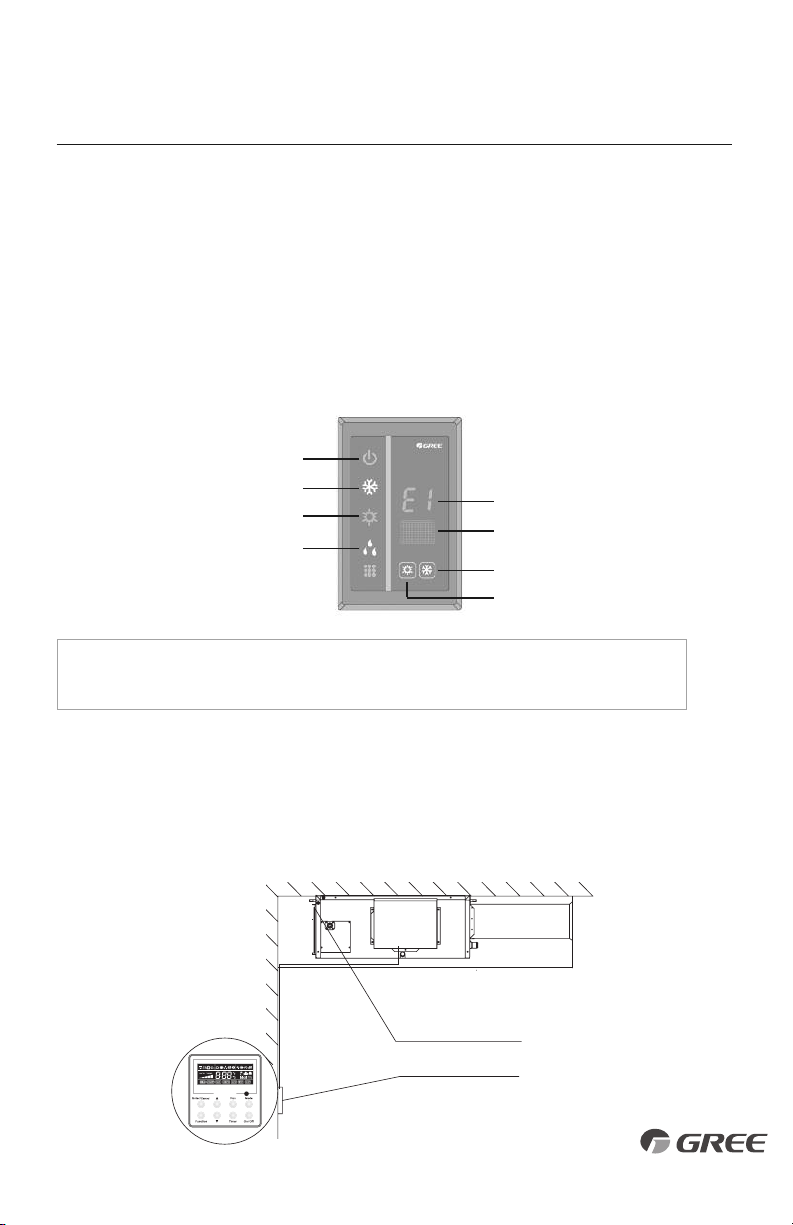
Unit Control Indicators
The Slim Duct unit has a basic user interface panel and display. It operates in conjunction with
the Programmable Controller.
There are two buttons on the panel. A"Cool" button which will force the unit into Cool Mode
with a 79° F (26° C) set temperature. And a"Heat" button which will force the unit into heat mode
with a 68° F (20° C) set temperature.
The dual 7-segment display will display error codes to speed up troubleshooting and repairs.
Setting Double Indoor Room Sensors
This series of ducted air conditioner has two indoor room sensors. One is located at the air intake
of the indoor unit and the other is located inside the Programmable Controller. The user can select
one from the two indoor room sensors on the basis of their own preference. Refer to the Owner's
Manual for detailed instructions.
27
CONTROLLER INSTALLATION AND SETUP
NOTE:
When the unit is connected with the wired controller, the error code will be
simultaneously shown on it.
Indoor room sensor A
I
Cooling indicator
Heating indicator
“88” display
Receiver
“Cool” button
“Heat” button
Indoor Unit
Power/Running
Indicator
Dehumidification
Indicator
Pogrammable Controller Indoor Room Sensor B
28
NOTE: You may want to perform leak testing and evacuation before wiring
to save time, electrical connections can be completed while your vacuum
pump is running.
Additional Charge
Refrigerant for the pipe length of 25 feet has been charged at the factory. If the piping is greater than
25 feet additional charging is necessary. For the additional amount, see the table below.
Model Add’l Refrigerant (oz/ft (g/m)
18,000 0.3 (30)
24,000 0.6 (60)
30,000 0.6 (60)
36,000 0.6 (60)
42,000 0.6 (60)
48,000 0.6 (60)
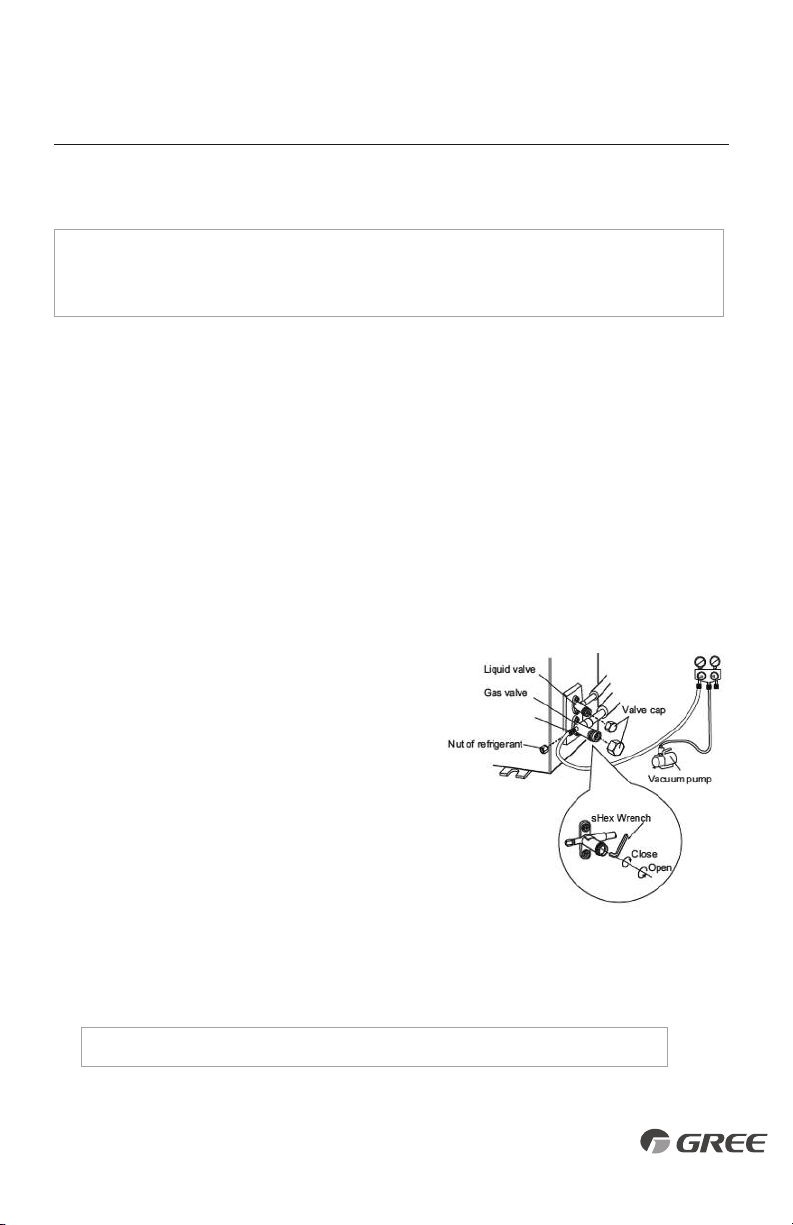
TESTING AND INSPECTION
Pressure gauge (low-pressure)
Pressure gauge (hi-pressure)
Gauge manifold
Connection pipe
Cap
Cap
Service pipe
Cap
Hose with the valve pin
Hose
Vacuum pump
Hose
Switch (hi-pressure)
Switch (low-pressure)
Connection pipe (to indoor unit)
Liquid valve
Gas valve
Service port
Pipe Testing
Leak Test
Refrigerant lines should be pressurized prior to evacuating system to check for leaks.
1. Connect regulated nitrogen to manifold. Attach hose to service port.
2. Open manifold valve to add nitrogen to a pressure of 500 lbs.
3. Maintain applied pressure for 30 minutes, leak-test flare fittings with soap bubbles. If no leak is
detected, release nitrogen.
Use vacuum pump, rather than refrigerant, to discharge air when installing the unit.
CAUTION
29
Vacuum Procedure
Important: Use a quality Micron Gauge to measure and validate the proper system vacuum
level achieved. Do not rely on the scale of a“bourbon tube”type gauge set to validate the
depth and quality of the vacuum.
1. Remove the caps of the liquid valve, gas valve and service port.
2. Connect gauge manifold and micron gauge to the service ports provided at the liquid and
suction service valves.
3. Connect a vacuum pump to the manifold gauge.
4. Open the lower pressure side of the manifold valve assembly and start the vacuum pump.
The switch at the high pressure side of the manifold valve assembly should be kept closed,
or evacuation does not fail.
5. Operate vacuum pump until a vacuum of 500 microns or less is achieved. The evacuation
duration depends on the vacuum pump size and unit’s capacity, generally 20 minutes for
the 9,000 BtuH units, to 1 hour for a larger 36,000 BtuH unit.
6. Close the manifold valves and shut off the pump.
a. If vacuum holds below 700 microns for 15
minutes, the system can be considered dry
and leak free. Go to step 5.
b. If vacuum increases to 800 microns or greater,
this is an indication of moisture in system
or a leak exists. Identify leak and repair as
necessary, after which repeat steps 4 and 5.
If moisture is suspect, purge system use triple
evacuation method using dry nitrogen.
7. Confirm that manifold valves are closed and disconnect the vacuum pump.
8. Open the service valves to the fully ‘back-seat’ position to let the refrigerant flow to the
indoor unit and balance the pressure in system.
Note: Do not allow air to enter the connection pipe when removing the hose.
9. Replace service valve caps and tighten.
TESTING AND INSPECTION
Service port
30
TESTING AND INSPECTION
Start-up Checklist
□ Turn on main power to indoor and outdoor units.
•
Verify the system is not displaying an error code on the indoor unit or Wired Programmable
Controller display.
□ Press the ON button on the
Wired Programmable
Controller.
• Verify the Wired Programmable Controller Controller display turns ON.
□ Press the Mode button to Cooling.
Adjust the room setpoint to bring the system on in cooling mode. The system should start
cooling mode within 3-5 minutes.
• Verify the outdoor fan and compressor are operating.
• Verify the indoor fan is operating.
• Verify the indoor discharge air is cooling the room.
□ Press the Mode button to Heating.
Adjust the room setpoint to bring the system on in heating mode. The system should start
heating mode within 3-5 minutes.
• Verify the outdoor fan and compressor are operating.
• Verify the indoor fan is operating.
• Verify the indoor discharge air is heating the room.
□
Press the OFF button on the Wired Programmable Controller.
• Verify Wired Programmable Controller display turns OFF and the system shuts OFF.
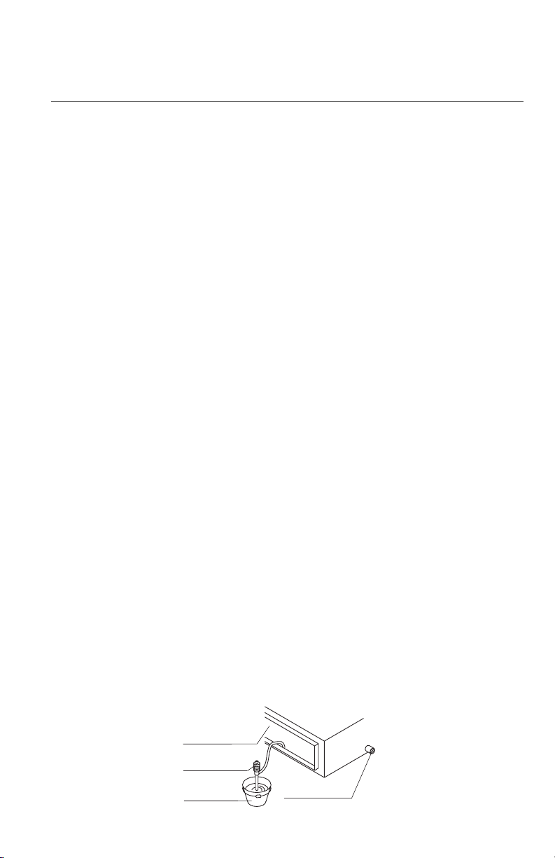
□
Test the Drain Piping.
• Verify condensate water drains smoothly. As shown in the figure, add approximately
1 quart of water slowly into the drain pan. The condensate pump should turn on and
drain the water through the condensate drain pipe to a safe location. Verify there are no
leaks
in the condensate pipe and connections.
Air outlet
Portable pump
Bucket
Drain outlet
31
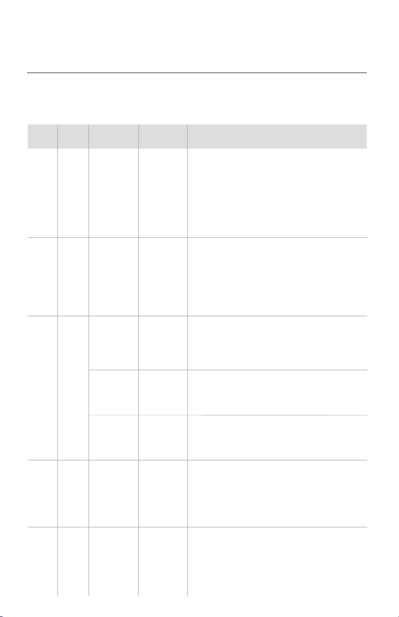
TROUBLESHOOTING
PROBLEM
System does not restart.
Indoor unit emits unpleasant odor
when started
You hear a“water flowing”sound.
A thin fog or vapor coming out
of the discharge register when
system is running.
You hear a slight cracking sound
when the system stops or starts.
The system will not run.
The unit is not heating or cooling
adequately.
CAUSE/SOLUTION
Cause: The system has a built-in three-minute delay to prevent short and/or rapid
cycling of the compressor.
Solution: Wait three minutes for the protection delay to expire.
Cause: Typically unpleasant odors are the result of mold or mildew forming on
the coil surfaces or the air filter.
Solution: Wash indoor air filter in warm water with mild cleaner. If odors persist,
contact a qualified service professional to clean the coil surfaces.
Cause: It is normal for the system to make“water flowing”or “gurgling”sounds
from refrigerant pressures equalizing when the compressor starts and stops
Solution: The noises should discontinue as the refrigerant system equalizes after
two or three minutes.
Cause: It is normal for the system to emit a slight fog or water vapor when
cooling extremely humid warm air.
Solution: The fog or water vapor will disappear as the system cools and
dehumidifies the room space.
Cause: It is normal for the system to make “slight cracking” sounds from parts
expanding and contracting during system starts and stops.
Solution: The noises will discontinue as temperature equalizes after 2 or 3 minutes.
Cause: There are a number of situations that will prevent the system from running.
Solution: Check for the following:
• Circuit breaker is “tripped” or “turned off.”
• Power button of Wired Programmable Controller is not turned on.
• Wired Programmable Controller is in sleep mode or timer mode.
• Otherwise, contact a qualified service professional for assistance.
Cause: There are a number of reasons for inadequate cooling or heating.
Solution: Check the following:
• Remove obstructions blocking airflow into the room.
• Clean dirty or blocked air filter that is restricting airflow into the system.
• Seal around door or windows to prevent air infiltration into the room.
• Relocate or remove heat sources from the room.

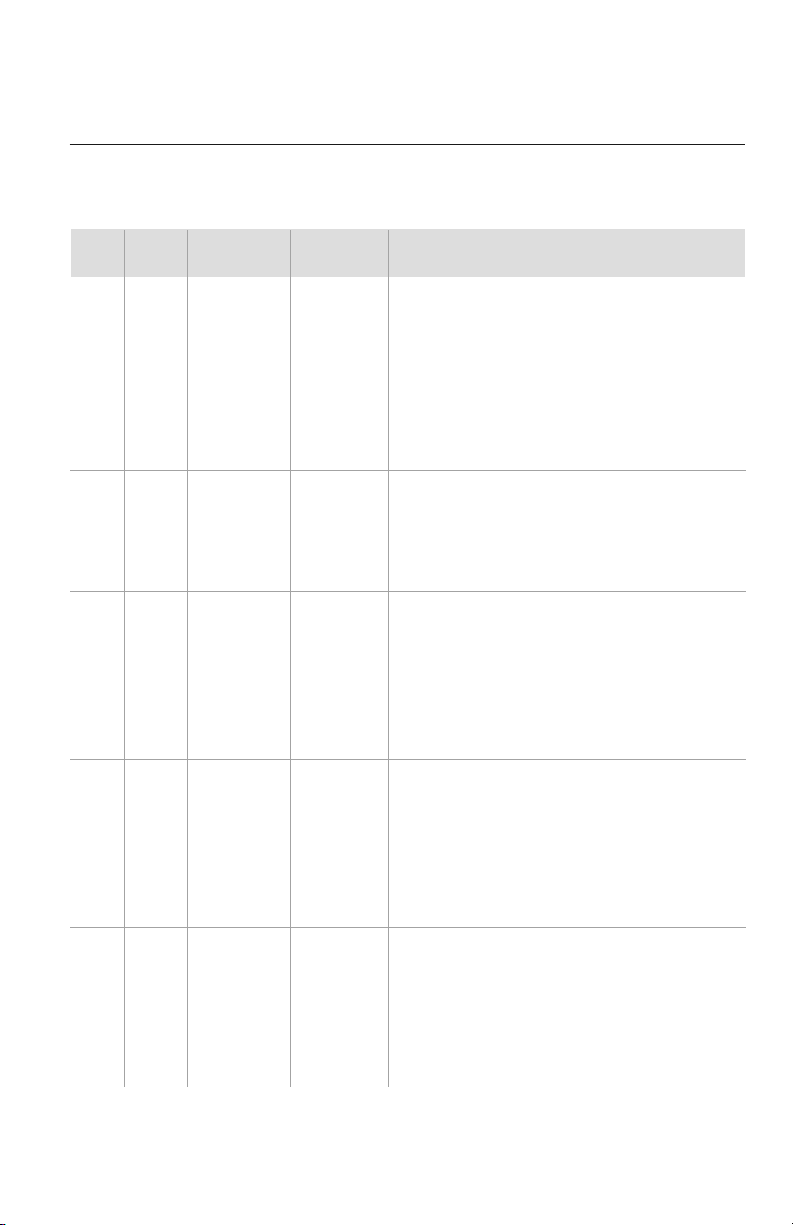
TROUBLESHOOTING
PROBLEM
Water leakage from the
outdoor unit.
Water leaking from the indoor
unit into the room.
The unit will not deliver air.
CAUSE/SOLUTION
Cause: It is normal for the outdoor unit to generate condensate water in the
reverse cycle heating and defrost mode.
Solution: This is normal. No action is required.
Cause:
While it is normal for the system to generate condensate water in cooling
mode, it is designed to drain this water via a condensate drain system to a safe location.
Solution: If water is leaking into the room, it may indicate one of the following.
• The indoor unit is not level right to left. Level indoor unit.
• The condensate drain pipe is restricted or plugged. All restrictions must
be removed to allow continuous drainage by gravity.
• If problem persists, contact a qualified service professional for assistance.
Cause: There are a number of system functions that will prevent air flow.
Solution: Check for the following:
• In heating mode, the indoor fan may not start for three minutes if the
room temperature is very low. This is to prevent blowing cold air.
• In heat mode, if the outdoor temperature is low and humidity is high,
the system may need to defrost for up to 10 minutes before beginning
a heating cycle.
• In dry mode, the indoor fan may stop for up to three minutes during the
compressor off delay.
• Otherwise, you should contact a qualified service professional for assistance.
32
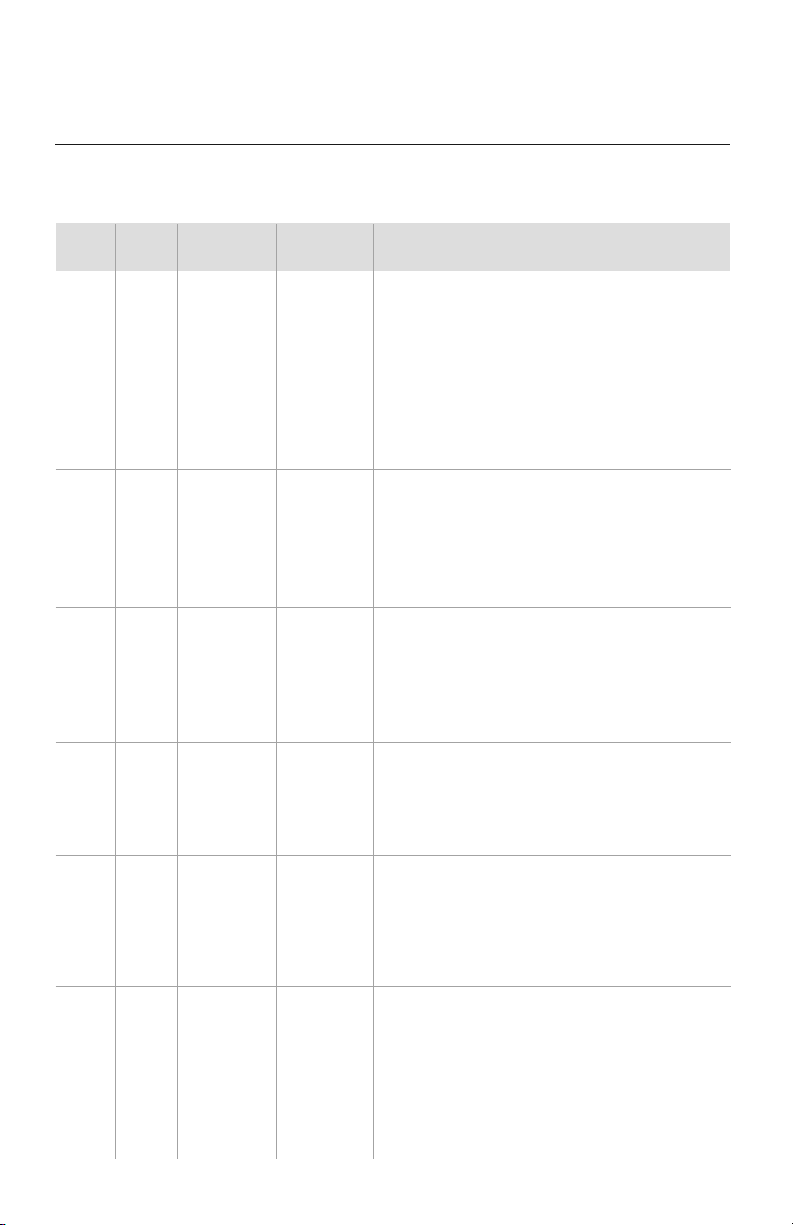
33
DIAGNOSTIC CODES
No.
1
2
3
4
5
Description
If outdoor unit detects the high pressure switch is cut off for 3-sec
successively, high pressure protection will occur. All the loads
(except the 4-way valve in heating mode) will be switched off.
In this case, all the buttons and remote control signals except
ON/OFF button will be disabled and system won't be recovered
automatically. Switch off the unit or re-energize the unit after
cutting off power to eliminate this protection.
If indoor unit detects the evaporator temperature is lower than
protective temperate value after the unit has been running for a
period of time under cooling or dry mode, the unit will report this fault,
in which case the compressor and outdoor fan motor will be stopped.
The unit will not run until evaporator temperature is higher than
the protective temp. value and the compressor is stopped for 3-min.
If outdoor unit detects low-pressure switch is open during ON or
standby state within 30-sec successively the unit will report a low
pressure protection. If the fault occurs 3 times successively within
30-min, the unit will not recover automatically.
If the unit reports low refrigerant level within 10-min after turning on
the unit, the unit will stop operation. If the fault occurs successively
3 times, the unit cannot be recovered automatically.
If the unit enters refrigerant recovery mode through special
operation, E3 will be displayed. After exiting refrigerant recovery
mode, the code will disappear.
If outdoor unit detects the discharge temperature is higher than
protective temperature value, the unit will report high discharge
temperature protection. If the protection occurs over 6 times, the
unit cannot be recovered automatically. Switch off the unit or
re-energize the unit after cutting off power to reset this protection.
If the outdoor unit does not receive data from indoor unit,
communication malfunction will be reported. If there is
communication abnormality between display board and indoor
unit, communication malfunction will be reported.
Error
Code
E1
E2
E3
E4
E6
Malfunction
Name
High Pressure
Protection
Indoor Coil
Freeze
Protection
Low Pressure
Protection
Low
Refrigerant
Protection
Refrigerant
Recycling
Mode
Compressor
High Discharge
Temperature
Protection
Communication
Malfunction
Origin of
Malfunction
High Pressure
Switch
Indoor
Evaporator
Temperature
Sensor
Low Pressure
Switch
Compressor
Discharge
Temperature
Communication
Failure Between
Indoor and
Outdoor Main
Board
The U-Match System has on board diagnostics. The indoor unit and Wired Programmable
Controller will display error codes. The following is a summary of the codes with explanation:
Error Codes
34
DIAGNOSTIC CODES
No.
6
7
8
9
10
Description
If the indoor unit does not receive signal from indoor fan motor
for 30-sec successively when the fan motor is operating, indoor
fan motor malfunction will be reported. In this case, the unit can
automatically resume operation after stopping. If the malfunction
occurs 6 times within one hour, the unit cannot be recovered
automatically. Switch off the unit or re-energize the unit after
cutting off power to eliminate this malfunction.
If indoor unit detects the condensate overflow switch warning for
8-sec successively, the system will enter condensate overflow
protection. The unit will shut off and will not recover automatically.
Switch unit off and then switch it on to eliminate this malfunction.
If indoor unit detects the indoor ambient temperature sensor is open
circuit or short circuit for 5-sec successively, indoor ambient temp.
sensor malfunction will be reported. The unit can automatically
resume operation after the malfunction disappears. If indoor ambient
temperature sensor malfunction occurs in fan mode, only the error
code is displayed and the indoor unit will operate normally.
If indoor unit detects the evaporator temperature sensor is open
circuit or short circuit for 5-sec successively, evaporator temperature
sensor malfunction will be reported. The unit can automatically
resume operation after the malfunction disappears. If evaporator
temperature sensor malfunction occurs in fan mode, only the error
code is displayed and the indoor unit will operate normally.
If outdoor unit detects the condenser coil temperature sensor open
circuit or short circuit for 5-sec successively, condenser coil temperature
sensor malfunction will be reported. The unit can automatically
resume operation after the malfunction disappears. If condenser
temperature sensor malfunction occurs in fan mode, only the error
code is displayed and the indoor unit will operate normally.
Error
Code
E8
E9
F0
F1
F2
Malfunction
Name
Condensate
Overflow
Protection
Indoor Ambient
Temperature
Sensor at
Return Air Inlet
Malfunction
Indoor
Evaporator Coil
Temperature
Sensor
Malfunction
Indoor
Condenser Coil
Temperature
Sensor
Malfunction
Origin of
Malfunction
Indoor
Fan Motor
Overflow
Switch
Indoor
Ambient
Temperature
Sensor
Evaporator
Coil
Temperature
Sensor
Condenser
Coil
Temperature
Sensor
Error Codes
35
DIAGNOSTIC CODES
No.
11
12
13
14
15
16
Description
If outdoor unit detects the outdoor ambient temperature sensor
open circuit or short circuit for 5-sec successively, outdoor ambient
temperature sensor malfunction will be reported. The unit can
automatically resume operation after the malfunction disappears.
If outdoor ambient temperature sensor malfunction occurs in fan
mode, only the error code is displayed and the indoor unit will
operate normally.
If outdoor unit detects the compressor discharge temperature
sensor is open circuit or short circuit for 5-sec successively after
the compressor has been operating for 3-min, outdoor discharge
temperature sensor malfunction will be reported. The unit can
automatically resume operation after the malfunction disappears.
If the Wired Programmable Controller detects open circuit or
short circuit of its temperature sensor for 5-sec successively,
wired controller
temperature sensor malfunction will be
reported.
If the memory chip of outdoor drive circuit board fails, the unit will
not start. The unit will not recover automatically. If thermo junction
cannot be eliminated after switching off the unit and then energizing
the unit several times, replace the outdoor drive circuit board.
If outdoor unit detects the compressor overload switch open within
3-sec successively, the unit will report compressor overload protection.
If the fault occurs successively 3 times, the unit will not recover
automatically. Switch off the unit or re-energize the unit to eliminate
this protection.
If indoor unit detects the evaporator coil temperature is higher
than protective temp. value, the unit will report overload protection.
The unit will restart operation after evaporator temperature is lower
than the protective temp. value and the compressor is stopped for
3-minutes. If the protection occurs over 6 times, the unit will not
recover automatically. Switch off the unit or re-energize the unit
to eliminate this protection.
Error
Code
F3
F4
F5
ee
H3
H4
Malfunction
Name
Outdoor
Ambient
Temperature
Sensor
Malfunction
Compressor
Discharge
Temperature
Sensor
Malfunction
Wired
Controller
Temperature
Sensor
Malfunction
Outdoor
Drive
Memory Chip
Malfunction
Compressor
Overload
Protection
Overload
Protection
Origin of
Malfunction
Outdoor
Ambient
Temperature
Sensor
Compressor
Discharge
Temperature
Sensor
Wired
Controller
Temperature
Sensor
Outdoor Drive
Board
Compressor
Overload
Switch
Evaporator
Temperature,
Condenser
Temperature
Error Codes
36
DIAGNOSTIC CODES
No.
17
18
19
20
Description
If outdoor unit does not receive feedback signal from outdoor fan
motor for 30-sec successively when the fan motor is operating, an
outdoor fan motor malfunction will be reported. In this case, the unit
can automatically resume operation after stopping. If the malfunction
occurs 6 times within one hour, the unit will not recover automatically.
Switch off the unit or re-energize the unit to eliminate this malfunction.
After the compressor starts operation in heating mode, if the outdoor
unit detects the difference between evaporator temperature and
indoor ambient temperature is lower than the protective value for
10-min successively, Reversing Valve Malfunction will be reported
and the outdoor unit will stop operation. If the malfunction occurs
3 times, the unit will not recover automatically. Switch off the unit
or re-energize the unit to eliminate this malfunction.
If the outdoor main control board does not receive data from drive
board, communication malfunction between main control and drive
will be reported. The malfunction will be eliminated automatically.
If the memory chip on the outdoor main control board fails, the
unit will not start. The unit will not recover automatically. If thermo
junction cannot be eliminated after switching the unit off and on
for several tries, replace the outdoor main control board.
Error
Code
H6
U7
P6
EE
Malfunction
Name
Outdoor
Fan Motor
Malfunction
Reversing or
4-way Valve
Malfunction
Main Control
and Drive
Communication
Malfunction
Outdoor
Main Control
Memory Chip
Malfunction
Origin of
Malfunction
Outdoor
Fan Motor
Reversing/
4-way Valve
Communication
Failure Between
Indoor and
Outdoor Main
Board
Outdoor
Main Control
Board
Error Codes
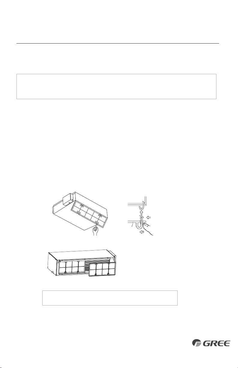
Routine Maintenance
CARE AND CLEANING
NOTE: Filters should be installed before operating the air conditioner, otherwise dirt or
dust could enter the unit. Do not remove the air filter except for cleaning.
Cleaning
The air filter should be cleaned every 90 days. Cleaning frequency should be increased if the
unit is installed in a room where there is an abnormal amount of dirt and dust.
1. Remove the air filter from the duct.
2. Clean the air filter. Remove dust from the air filter using a vacuum cleaner and gently
rinse in cool water with mild detergent. Don't use hot water to avoid filter shrinking or
deformation. After cleaning the filter, dry filter before replacing.
3. Replace the air filter.
Attach the filter to
the main unit while
pushing down on
the bend clasps.
Main Unit
Force
Force
Filter
Press the air filter downward
into the guided groove. Then
pull the top outward.
NOTE: The 24K-48K sizes have two separate air filters.
37
Gree Electric Appliances, Inc ©2020 Cat No: GREE_U-MATCH__INSTALL_SLIM DUCT_04222020
GREE ELECTRIC APPLIANCES, INC.
www.greecomfort.com
PRODUCT & INSTALLATION RECORD
For your convenience, please record the model and serial numbers of your new equipment in the
spaces provided. This information, along with the installation data and dealer contact information,
will be helpful should your system require maintenance or service.
UNIT INFORMATION
Outdoor Unit:
Model No.
Serial No.
Indoor Unit:
Model No.
Serial No.
INSTALLATION INFORMATION
Date Installed:
DEALERSHIP/INSTALLER INFORMATION
Company Name:
Address:
Phone Number:
Technician Name: