Loading ...
Loading ...
Loading ...
www.PyleUSA.com12 www.PyleUSA.com 13
25. [USB INTERFACE] Use for MP3 input or computer connection (can be used
for U disk or computer software recording)
26. [PROGRAM] Control Knob - Push down and turn this control knob to select
one of the sixteen built-in sound eect modes.
27. [HIGH-LOW] The two-band equalizer adjusts the level of the two bands
Mp3 player.
28. [+48V PHANTOM POWER] This switch toggles phantom power on and o.
When the switch is on the mixer supplies +48V phantom power to all channels
that have XLR mic input jacks.Turn this switch on when using one or more
phantom-powered condenser microphones.
29. [+48V INDICATOR] This indicator lights up when the +48V power is ON.
30. [POWER INDICATOR] This indicator lights up when the mixer's power is ON.
31. [PFL] After pressing the PFL button, the PFL indicator light will be up.
32. [LEVEL METER] Shows the level Signal's strength.
33. [FX TO AUX] Adjust the eect value to AUX 1 and AUX 2 output.
34. [AUX1 & AUX2] Adjust the volume of AUX 1 and AUX 2 outputs.
35. [RETURN] Level controller, adjust the return level.
36. [SUB SWITCH] Press SUB to send the signal to the headphone jack output.
37. [MAIN SWITCH] Press MAIN to send the signaI to the headphone jack output.
38. [PHONES CONTROL] Controls the level of the signal output to the PHONES
jack OUT jacks.
39. [FX SEND FADER] Control eect input signal level.
40. [MP3 VOL FADER] Adjust VOL button to control the MP3 VOL.
41. [SUB] Level ControlFader: This level control fader is used to raise or lower
the SUB output level.
42. [MAIN MIX FADER] Use the high-precision quality faders to control the
VOL output level of the main mix. Built-In power amplier.
43. [FUSE HOLDER/IEC MAINS RECEPTACLE] The console is connected to the
mains via the cable supplied, which meets the required safety standards.
Blown fuses must only be replaced by fuses of the same type and rating.
The mains connection is made via cable with IEC mains connector.
44. POWER SWITCH
Installation
CAUTION!
NEVER USE unbalanced XLR connectors
(PIN 1 and 3 connected) at the MIC input
jacks if you want to use the phantom
power supply.
Cable Connections
You will need a large amount of cables
for the various connections of the console.
The image below shows the wiring of
these cables. Use only HIGH GRADE cables
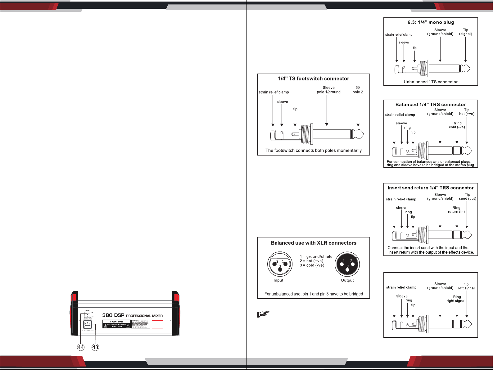
Foot Switch Connector
Audio Connections
Use commercial RCA cables to wire the
2-track input and output. You can also
connect unbalanced devices to the
balanced input/output. Use either mono
plugs, or use stereo plugs to link the ring
and shaft (or pins 1 & 3 in the case of
XLR connectors).
XLR Connections
6.3: 1/4” Mono Plug
Balanced 1/4” TRS Connector
Insert Send/Return Stereo Plug
1/4” TRS Headphones Connector
Loading ...
Loading ...