
Safety,Assembly®Operation,Adjustment,Maintenance,Troubleshooting, Warranty
Transmatic Lawn Tractor- Models 760°779
READ SAFETY RULES AND mNSTRUCTmONS CAREFULLY BEFORE OPERATION
Warning: This unitis equippedwithan internalcombustionengineandshouldnot beusedon or nearany unimprovedforest-covered,brush=
coveredor grass=coveredlandunlessthe engine'sexhaustsystemis equippedwith a sparkarrestermeetingapplicablelocalorstate laws (if any),
If a sparkarresteris used, it shouldbemaintainedin effectiveworkingorderby the operator,Inthe Stateof Californiathe aboveis requiredbylaw
(Section4442of the CaliforniaPublicResourcesCode),Otherstatesmayhavesimilarlaws,Federallaws applyonfederallands,A sparkarrester
for the muffleris availablethroughyournearestengineauthorizedservicedealeror contactthe servicedepartment,RO,Box361131Cleveland,
Ohio44136=0019,
FORMNO,769=02189A
PRINTEDIN U,S,A, MTD LLC, P.O. BOX 361131 CLEVELAND, OHIO 44136-0019 01/06/2006

This Operator's Manual is an important part of your new lawn tractor, mtwill help you assemble,
prepare and maintain the unit for best performance. Please read and understand what it says.
Table of Contents
Slope Gauge ....................................................... 3
Safe Operation Practices ................................... 4
Setting Up Your Lawn Tractor ............................ 8
Operating Your Lawn Tractor ........................... 12
Adjusting Your Lawn Tractor ............................ 20
Maintaining Your Lawn Tractor ........................ 22
Off-Season Storage / Attachments ................. 28
Safety Labels .................................................... 29
Trouble Shooting .............................................. 30
Warranty .............................................. Back Page
Finding and Recording Model Number
BEFOREYOU STARTASSEMBLING
YOUR NEW EQUIPMENT,
please locatethe model plate on the equipment and copy the
information to the sample model plate providedto the righL
You can locate the model plate by looking beneathethe seal
This information will be necessary to use the manufacturer's
web site and/or obtain assistance from the Customer Support
Department or an authorizedservice dealer.
f
Modem Number
www, mtdpreducts,com
Serial Number
MTD LLC
P.O. BOX 361131
CLEVELAND, OH 44136
330-220-4683
800-800-731 0
Customer Support
Please do NOTreturn the unit to the retailer from which it was
purchased, without first contacting Customer Support.
if you have difficulty assembling this product or have any questions regardingthe controls,operation, or maintenanceof this
unit, you can seek help from the experts. Choose from the options below:
1. Visit mtdproducts.com Click on the Service & Support menu option.
2_ Phonea Customer Support Representative at (800) 800=7310_
3. The engine manufacturer is responsiblefor all engine-related issues with regardsto performance, power=rating,specificao
tions, warranty and service. Please refer to the engine manufacturer'sOwner's/Operator's Manual, packed separatelywith
your unit, for more information.
Prod_J_ P_e gistr,_tio n
2
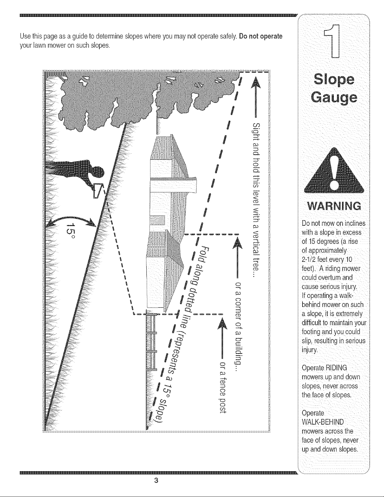
yourlawnmoweronsuchslopes.
/
/
/
/
o
/
/
t
o
w_
WARNING
Do not mowon inclines
with a dope in excess
of 15 degrees (a rise
of approximately
2-"
feet). A riding r
could overturn and
cause serious injury.
if operating a walb
behind mower on such
a dope, it is extremely
footing and you could
dip, resultingin serious
injury.
Operate RiDiNG
mowers up and down
dopes, neveracross
the face of dopes.
Operate
WALK-BEHIND
mowers across the
face of dopes, never
up and down slopes.
\
3
_i i _ i _i _ i _ iii _ _
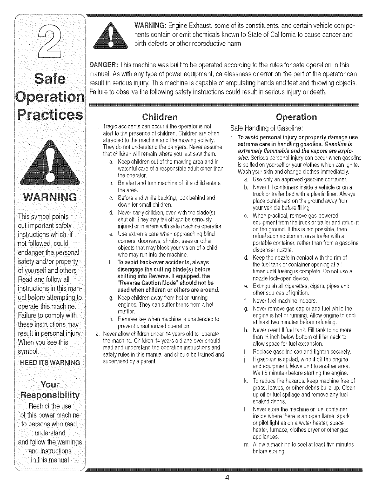
DANGER: This machine was built to be operated according to the rubs for safe operation in this
manuak As with any type of power equipment, carelessness or error on the part of the operator can
S ale result in serious injury. This machineis capable of amputating hands and feet and throwing objects.
Failureto observe the following safety instructions could result in serious injury or death.
instructionswhich, if
notfollowed, could
endangerthe personal
safety and/or property
of yourself and others.
Read and fobow all
instructionsin this man=
ual before attempting to
operatethis machine.
Failureto comply with
When you see this
symbol.
H EED ITS WARNING
Your
Responsibility
Restrictthe use
of this power machine
to persons who read.
understand
and follow the warnings
and instructions
in this manual
Children
1. Tragicaccidentscan occurif the operatoris not
abrt tothe presenceof children.Childrenare often
attractedto the machineand the mowingactivity.
Theydo not understandthe dangers.Neverassume
thatchildrenwill remainwhereyou last saw them.
a. Keepchildrenout of the mowingareaandin
watchfulcare of a responsibleadult otherthan
the operator.
b. Bealert and turn machineoff if a childenters
the area.
c. Beforeandwhile backing,lookbehindand
downfor smallchildren.
d. Nevercarrychildren,evenwiththe blade(s)
shutoff.They mayfalloff and be seriously
iniuredor interferewithsafemachineoperation.
e. Useextremecarewhenapproachingblind
corners,doorways,shrubs,trees or other
objectsthat mayblock yourvision of a child
who mayrun into the machine.
f. To avoid back-overaccidents, always
disengage the cutting blade(s) before
shifting into Reverse. If equipped, the
"Reverse Caution Mode" should not be
used when children or others are around.
g. Keepchildrenaway from hotor running
engines.Theycansuffer burnsfroma hot
muffler.
h. Removekeywhen machineis unattendedto
preventunauthorizedoperation.
2. Neverallowchildrenunder 14yearsold to operate
the machine.Children14}'earsold and overshould
readandunderstandthe operationinstructionsand
safetyrubs inthis manualand shouldbetrainedand
supervisedbya parent.
Operation
Safe Handling of Gasoline:
1. Toavoid personal injuryor property damage use
extreme care in handlinggasoline. Gasoline is
extremely flammable and the vapors are explo-
sive. Seriouspersonaliniurycanoccurwhengasoline
is spilledonyourselfor yourclotheswhichcan ignite.
Washyourskin andchangeclothesimmediately.
a. Useonlyan approvedgasolinecontainer.
b. Neverfill containersinsidea vehbb or ona
truckor trailerbed with a plastb liner.Always
placecontainerson the groundawayfrom
yourvehble beforefilling.
c. When practbal, removegas-powered
equipmentfromthe truck ortrailerand refuelit
onthe ground.Ifthis is not possibb, then
refuelsuch equipmentona trailerwitha
portabb container,ratherthan from agasoline
dispensernozzb.
d. Keepthe nozzb in contactwith the rimof
the fueltankor containeropeningat all
timesuntilfuelingis complete.Donot usea
nozzleIocbopendevice.
e. Extinguishall cigarettes,cigars,pipesand
othersourcesof ignition.
f. Neverfuel machineindoors.
g. Neverremovegas cap oraddfuel whilethe
engineis hot or running.Mow engineto cool
at bast two minutesbeforerefueling.
h. Neveroverfill fuel tank.Fill tank to nomore
than1/2inchbelowbottomof filbr neck to
allowspacefor fuel expansion.
i. Replacegasolinecapandtightensecurely.
i. If gasolineis spilled,wipe it off the engine
andequipment.Moveunitto anotherarea.
Wait5 minutesbeforestartingthe engine.
k. To reducefire hazards,keepmachinefreeof
grass,leaves,or other debrisbuild-up.Clean
upoil orfuel spillageand removeany fuel
soakeddebris.
I. Neverstorethe machineorfuel container
insidewherethere is anopenflame,spark
or pilotlightas on a waterheater,space
heater,furnace,clothesdryeror othergas
appliances.
m. Allowa machineto cool at bast five minutes
beforestoring.
4
GeneralOperation:
1. Read,understand,and followall instructionson the
machineandinthe manual(s)beforeattemptingto
assembleand operate.Keepthis manualina safe
placefor future and regularreferenceand forordering
replacementparts.
2. Befamiliarwithall controlsandtheirproperoperation.
Knowhow to stopthe machineand disengagethem
quickly.
3. Neverallowchildrenunder 14yearsold to operate
this machine.Children14yearsold and overshould
readandunderstandthe operationinstructionsand
safetyrubs in thismanualandshouldbetrainedand
supervisedby a parent.
4. Neverallowadults to operatethis machinewithout
properinstruction.
5. To helpavoid bladecontactor a thrownobiect iniury,
keepbystanders,helpers,childrenand petsat bast
75 feetfromthe machinewhileit is in operation.8top
machineif anyoneentersthe area.
6. Thoroughlyinspectthearea wherethe equipmentis to
beused.Removeallstones,sticks,wire,bones,toys,
andotherforeignobiectswhichcould bepickedup
andthrownbythe blade(s).Thrownobiectscancause
seriouspersonaliniury.
7, Planyourmowingpatternto avoiddischargeof
materialtowardroads,sidewalks,bystandersandthe
like.Also,avoiddischargingmaterialagainsta wall or
obstructionwhichmaycausedischargedmaterialto
ricochetback towardthe operator.
8. Alwayswearsafety glassesor safetygogglesduring
operationand while performingan adiustmentor
repairto protectyour eyes.Thrownobiectswhich
ricochetcan causeseriousiniuryto the eyes.
9. Wearsturdy,rough-sobdworkshoes and close-fitting
slacksandshirts.Loosefittingclothesand iewelry
can be caught in movabb parts. Neveroperatethis
machinein barefeetor sandals.
10.Be awareof the mowerand attachmentdischarge
directionanddo notpoint it at anyone.Do notoperate
the mowerwithoutthe dischargecoverorentiregrass
catcherin its properplace.
11.Do notput handsor feetnear rotatingpartsor under
the cuttingdeck.Contactwith the blade(s)can
amputatehandsandfeet.
12.Amissingor damageddischargecovercan cause
bladecontactor thrownobiectiniuries.
13.8topthe blade(s)whencrossinggraveldrives,walks,
or roadsand whilenot cuttinggrass.
14.Watchfor traffic whenoperatingnearor crossing
roadways.Thismachineis not intendedfor useon
anypublic roadway.
15.Do notoperatethe machinewhileunderthe influ-
enceof alcoholordrugs.
16.Mowonly in daylightor good artificiallight.
17,Nevercarry passengers.
18.Disengageblade(s)beforeshiftinginto reverse.
Backupslowly.Alwayslookdownand behind before
andwhilebackingto avoida back-overaccident.
19.Slowdownbeforeturning.Operatethe machine
smoothly.Avoiderraticoperationand excessive
instructions wh ch. if
not followed, could
endanger the personal
safety and/or property
of yourself and others.
Read and follow all
instructions in this man-
ual before attempting to
operatethis machine.
these instructions may
result in personal injury.
When you see this
symbol.
HEED iTS WARNING
Your
Responsibility
Restrictthe use
d this power machine
to persons who read,
understand
and follow the warninas
and instructions
in this manual
5
21.Neverleavea runningmachineunattended.Always
turnoff blade(s), placetransmissionin neutral,set
parkingbrake,stop engineand removekeybefore
dismounting.
22.Useextracare whenloadingor unloadingthe
machineintoa trailerortruck. This unitshould not
bedrivenupor downramp(s),becausethe unit
couldtip over,causingseriouspersonaliniury.The
unit mustbepushedmanuallyonramp(s)to load or
unloadproperly.
23.Mufflerandenginebecomehotand can causea
burn.Do nottouch.
24.Checkoverheadclearancescarefullybeforedriving
underlowhangingtreebranches,wires,dooropen-
ingsetc. wheretheoperatormaybe struckor pulled
fromthe unit,which couldresultinseriousiniury.
25.Disengageall attachmentclutches,depressthe
brakepedalcompbtely and shift into neutralbefore
attemptingto startengine.
26.Yourmachineis designedto cut normalresidential
grassof aheightno morethan 10".Do notattemptto
mowthroughunusuallytall, dry grass(e.g.,pasture)
or pilesof dry leaves.Drygrassor leavesmay
contactthe engineexhaustand/orbuildup onthe
mowerdeckpresentinga poten%l fire hazard.
27.Use onlyaccessoriesand attachmentsapprovedfor
thismachineby the machinemanufacturer.Read,
understandandfollowall instructionsprovidedwith
the approvedaccessoryor attachment.
28.Data indicatesthatoperators,age 60 yearsand
above,areinvolvedin a largepercentageof riding
mower-relatediniuries.Theseoperatorsshould
evaluatetheirability to operatetheriding mower
safelyenoughto protectthemselvesand others from
seriousiniury.
29.If situationsoccur whicharenot coveredin this
manual,usecareandgoodiudgment.Contactyour
customerservicerepresentativefor assistance.
WARNING
This symbol points
speed. }
20.Dbengageblade(s),setparkingbrake,stop engine
andwaituntilthe blade(s)cometo acompletestop
beforeremovinggrasscatcher,emptyinggrass,
uncloggingchute,removingany grassor debris,or
makinganyadiustments.
Slope Operation:
Slopesare a majorfactorrelatedto lossof controland
tip-overaccidentswhichcan resultin severeinjury or
death,All slopesrequireextracaution,if you cannot
backupthe slopeor if youfeel uneasyon it, do notmow
it,
Foryour safety,usethe slopegaugeincludedas partof
thismanualto measureslopesbeforeoperatingthis unit
ona slopedor hillyarea,if the slopeis greaterthan 15
;_,_ degreesas shownon the slopegauge,do notoperate
,, thisunit on that area or serious injurycouldresult,
uperal:lon Do:
1, Mow up and downslopes,notacross,Exercise
racl:lces extremecautionwhenchangingdirectiononsbpes,
2, Watchfor hobs, ruts,bumps,rocks,or other hidden
objects,Uneventerraincouldoverturnthe machine,
out important safety
instructions which, if
not followed, could
endangerthe personal
safety and/or property
of yourself and others.
Readand follow all
instructions in this man°
ual before attempting to
Tallgrasscan hide obstacbs,
3, Use slow speed,Choosea low enoughspeed
settingso that youwill not haveto stoporshift while
onthe slope,Tires may losetractiononslopeseven
thoughthe brakesare functioningproperly,Always
keepmachinein gear whengoingdownslopesto
takeadvantageof engine brakingaction,
4, Followthe manufacturer'srecommendationsfor
wheelweightsor counterweightsto improvestability,
5, Use extra carewithgrasscatchersor otherat-
tachments,Thesecanchangethe stabilityof the
machine,
6, Keepall movementon theslopesslowandgradual
Do not makesuddenchangesinspeedor direction,
Rapidengagementor brakingcouldcausethe front
of the machineto liftand rapidlyfib overbackwards
whichcouldcause seriousinjury,
7, Avoidstartingor stoppingon a slope,If tires lose
traction,disengagethe blade(s)andproceedslowly
straightdownthe slope,
Do Not:
1, Do notturn onslopesunlessnecessary;then,turn
slowlyand graduallydownhill,if possibb,
2, Do not mownear drop-offs,ditchesor embankments,
The mowercouldsuddenlyturnoverif awheel is over
the edgeof a cliff, ditch,or if anedgecavesin,
3, Do nottry to staNlizethe machineby puttingyourfoot
onthe ground,
4, Do not usea grasscatcheronsteep slopes,
5, Do not mowon wet grass,Reducedtractioncould
causesliding,
6, Do notshift to neutralandcoastdownhill Over-speed-
ingmaycausethe operatorto lose controlof the
machineresultingin seriousinjuryor death,
7, Do nottow heavypullbehindattachments(e,g,loaded
dumpcart, lawnroller,etc,)on slopesgreaterthan
5 degrees,Whengoingdown hill,the extra weight
tendsto pushthetractorand maycauseyou to loose
control (e,g,tractormayspeedup, brakingand steer-
ingabilityarereduced,attachmentmayjack-knifeand
causetractorto overturn),
Towing:
1, Towonlywitha machinethat hasa hitchdesignedfor
towing,Do not attachtowedequipmentexceptat the
hitchpoint,
2, Followthe manufacturersrecommendationfor weight
limitsfor towedequipmentand towingon slopes,
3, Neverallowchildrenor othersin or on towedequip-
ment,
4, On slopes,theweight of thetowedequipmentmay
causelossof tractionandlossof control,
5, Travelslowlyandallowextradistanceto stop,
6, Do notshift to neutralandcoastdownhill
these instructions may
result in personal injury,
When you see this
symbol
HEED ITS WARNING
YOUr
Responsibility
Restrictthe use
of this power machine
to persons who read.
understand
and follow the warnings
and instructions
in this manual
6
Service lO,Neverattemptto makeadiustmentsor repairsto the
1. Neverrun an engineindoorsor ina poorlyventilated
area. Engineexhaustcontainscarbonmonoxide,an
odorless,and deadlygas.
2. Beforecleaning,repairing,or inspecting,makecertain
the blade(s)andall movingpartshavestopped.
Disconnectthe sparkplug wireandgroundagainstthe
engineto preventunintendedstarting.
3. Periodicallycheckto make surethe bladescome to
compbte stop withinapproximately(5) five seconds
afteroperatingthe bladedisengagementcontrol,if the
bladesdo notstopwithin thethis timeframe,your unit
shouldbe servicedprofessionallyby an authorized
MTDServiceDealer.
4. Checkbrakeoperationfrequentlyas it is subiectedto
wearduring normaloperation.Adiustand serviceas
required.
5. Checkthe blade(s)andenginemountingboltsat
frequentintervalsfor propertightness.Also,visually
inspectblade(s)for damage(e.g. excessivewear,
bent,cracked). Replacethe blade(s)with theoriginal
equipmentmanufacturer's(O.E.M.)blade(s)only,
listedin thismanual."Useof partswhich do not meet
the originalequipmentspecificationsmaybad to
improperperformanceandcompromisesafety!"
6. Mowerbladesare sharp.Wrapthe bladeor wear
gloves,and useextra cautionwhenservicingthem.
7, Keepall nuts,bolts,andscrewstight to be surethe
equipmentis insafeworkingcondition.
8. Nevertamperwiththe safety interlocksystemor other
safetydevices.Checktheir properoperationregularly.
9. After strikinga foreignobiect,stop the engine,
disconnectthe spark plug wire(s)and groundagainst
the engine.Thoroughlyinspectthe machinefor any
damage.Repairthe damagebeforestartingand
operating,
machinewhile theengineis running,
11,Grasscatchercomponentsand the discharge
coveraresubiectto wearanddamagewhichcould
exposemovingpartsor allowobiectsto be thrown,
Forsafety protection,frequentlycheckcomponents
ii
andreplaceimmediatelywith originalequipment
manufacturer's(O,E,M,)partsonly,listedin this
manual,"Useof partswhich do notmeettheoriginal
equipmentspecificationsmaybad to improper
performanceandcompromisesafety!"
12,Do notchangethe enginegovernorsettingsor
over-speedthe engine,The governorcontrolsthe
maximumsafeoperatingspeedof theengine,
13,Maintainor replacesafety and instructionlabels,as
necessary,
14,Observeproperdisposallawsand regulationsfor
gas,oil,etc, to protecttheenvironment,
i /
This symbol points
instructions which, if
safety and/or property
of yourself and others,
Readand follow al
ual before attempting to
operatethis machine.
When you see this
symbol,
N EED roTSWARNING
Your
Responsibility
Restrictthe use
of this power machine
to persons who read,
understand
>wthe warnings
and instructions
in this manual
\
7
expiosivel Neverfue!
machineindoors
orwhiletheengine
Rubber Boot
©
\ //
Nut Hex Bolt
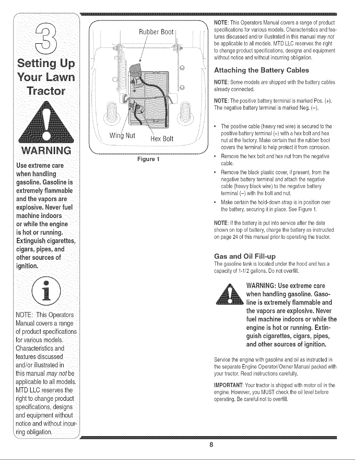
Figure 1
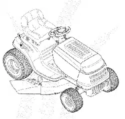
"_ NOTE:This OperatorsManualcoversa rangeof product
specificationsfor variousmodels,Characteristicsandfea=
turesdiscussedand/orillustratedin this manualmay not
beapplicableto all models,MTDLLC reservesthe right
to changeproduct specifications,designsandequipment
withoutnoticeand withoutincurringobligation,
Attaching the Battery Cables
NOTE:Somemodelsareshippedwiththe batterycables
alreadyconnected,
NOTE:The positivebatteryterminalis markedPos, (+),
The negativebatteryterminalis markedNeg, (-),
Thepositivecane (heavyredwire) is securedto the
positivebatteryterminal(+)with a hexbolt and hex
nut at thefactory,Makecertainthatthe rubberboot
coversthe terminalto helpprotectit fromcorrosion,
Removethehex bolt and hexnut from the negative
cable,
, Removetheblackplasticcover,if present,from the
negativebatteryterminaland attachthe negative
cane (heavyblackwire)to the negativebattery
terminal(-) withthe boltandnut,
Makecertainthehold=downstrapis in positionover
the battery,securingit in place,See Figure1,
NOTE:If the batteryis putinto serviceafterthe date
shownontop of battery,chargethe batteryas instructed
on page24of this manualpriorto operatingthe tractor,
Characteristics and
Gas and Oil Fill-up
The gasolinetankis locatedunderthe hoodandhasa
capacityof 1=1/2gallons, Do notoverfill,
WARNING: Use extreme care
when handling gasoline. Gaso-
line is extremely flammable and
the vapors are explosive. Never
fue! machine indoors or while the
engine is hot or running. Extin-
guish cigarettes, cigars, pipes,
and other sources of ignition.
Servicethe enginewith gasolineand oil as instructedin
the separateEngineOperator/OwnerManualpackedwith
yourtractor,Readinstructionscarefully,
IMPORTANT:Yourtractoris shippedwith motoroil in the
engine,However,you MUSTcheckthe oil levelbefore
operating,Becarefulnotto overfill,
8
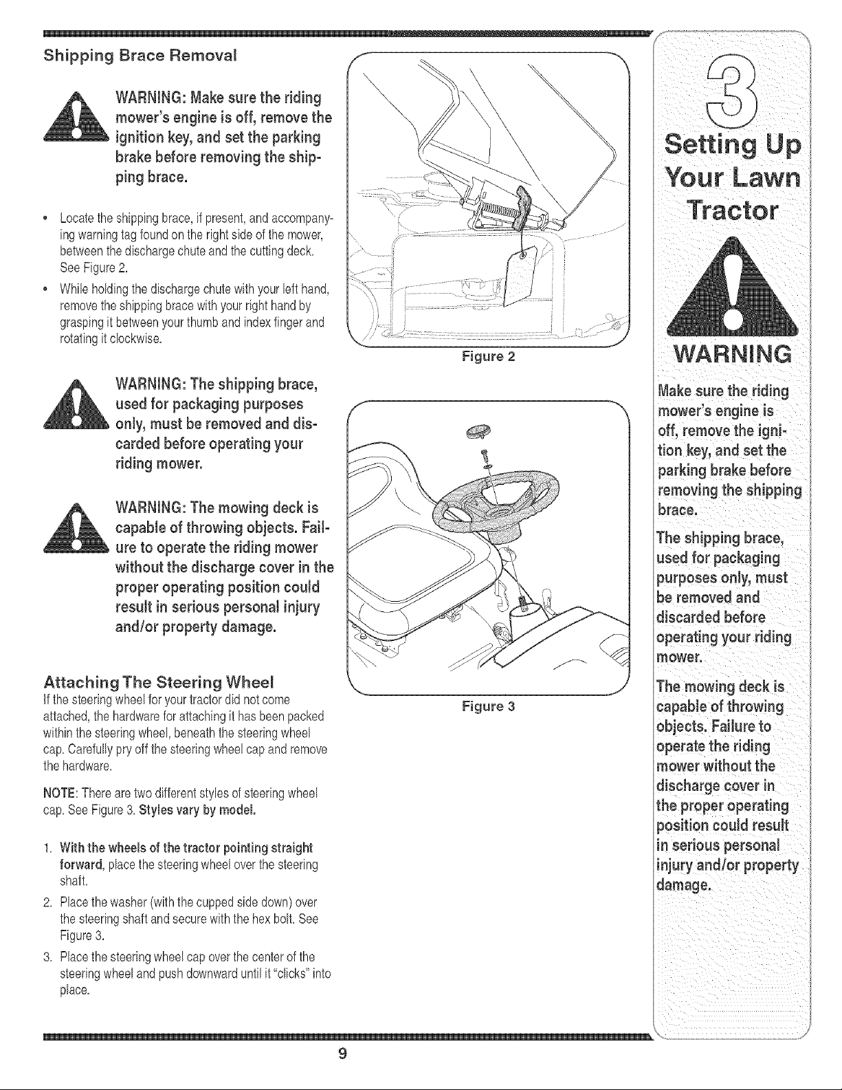
WARNING:Makesuretheriding
mower'sengineis off, remove the
ignition key, and set the parking
brake before removing the ship-
ping brace.
Locatethe shippingbrace,if present,and accompany=
ingwarningtagfoundon the rightside of the mower,
betweenthe dischargechuteand the cuttingdeck,
SeeFigure2,
• While holdingthe dischargechutewithyourleft hand,
removetheshippingbracewithyourright handby
graspingit betweenyourthumbandindexfingerand
rotatingit clockwise,
WARNING: The shipping brace,
used for packaging purposes
onJy,must be removed and dis-
carded before operating your
riding mower.
WARNING: The mowing deck is
capaMe of throwing objects. FaiF
ure to operate the riding mower
without the discharge cover in the
proper operating position could
resuJt in serious personal injury
and/or property damage.
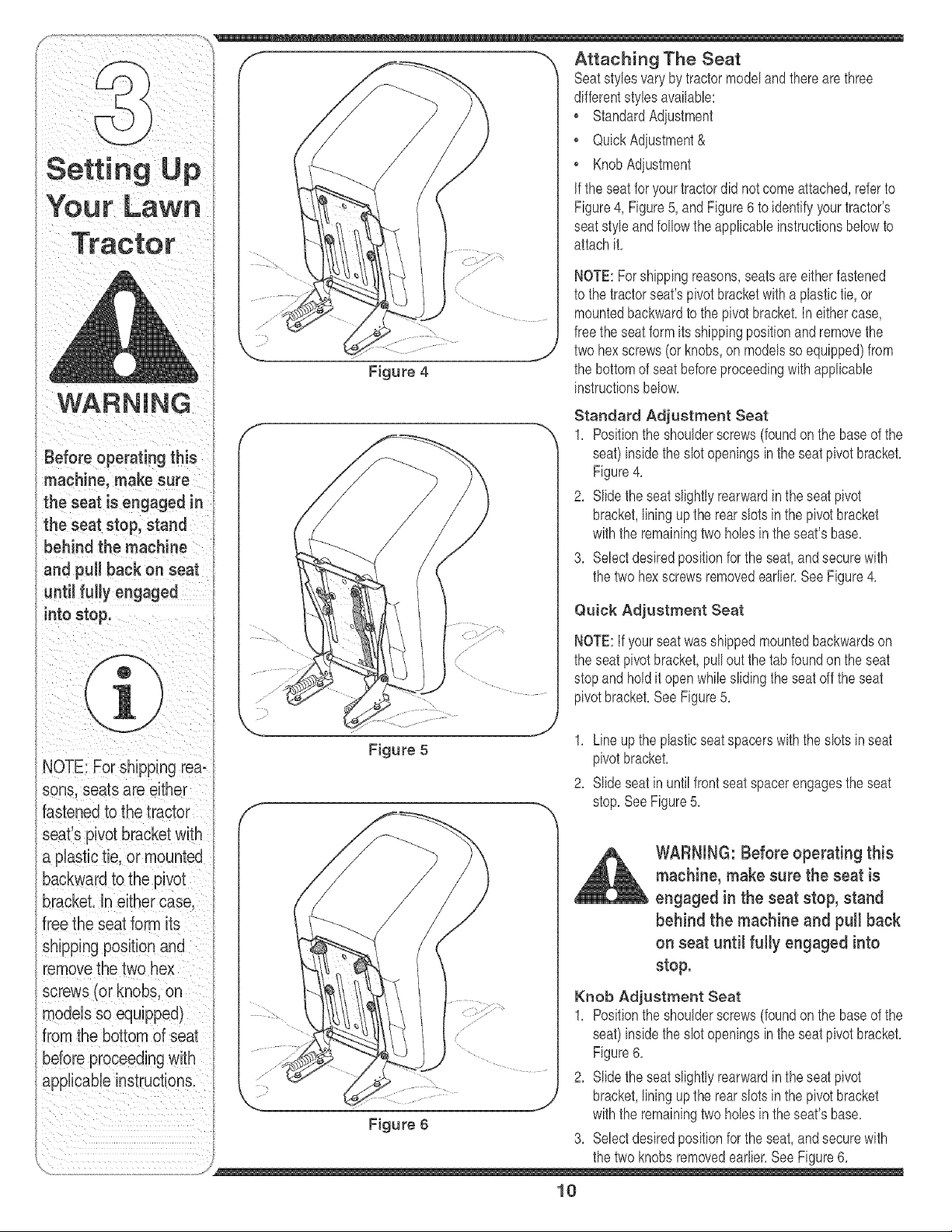
Attaching The Steering Wheel
if the steeringwheelfor yourtractordid notcome
attached,the hardwarefor attachingit hasbeenpacked
withinthe steeringwheel, beneaththe steeringwheel
cap,Carefullypry off thesteeringwheelcapand remove
the hardware,
NOTE:Therearetwo differentstylesof steeringwheel
cap,SeeFigure3, Styles vary by model.
Figure 2
Figure 3
1. With the wheels of the tractor pointing straight
forward, placethe steeringwheeloverthe steering
shaft,
2, Placethe washer(with thecuppedside down)over
the steeringshaftandsecurewiththe hex bolt,See
Figure3,
3, Placethe steeringwheelcap overthe centerof the
steeringwheeland pushdownwarduntilit"clicks" into
place,
Your Lawn
Tractor
WARNING
Make sure the riding
mower's engine is
off, remove the igni-
tion key, and set the
parking brake before
removing the shipping
brace.
The shipping brace,
used for packaging
purposes only, must
be removed and
discarded before
operating your riding
mower.
The mowing deck is
capable of throwing
objects. Failure to
operate the riding
mower without the
discharge cover in
the proper operating
9
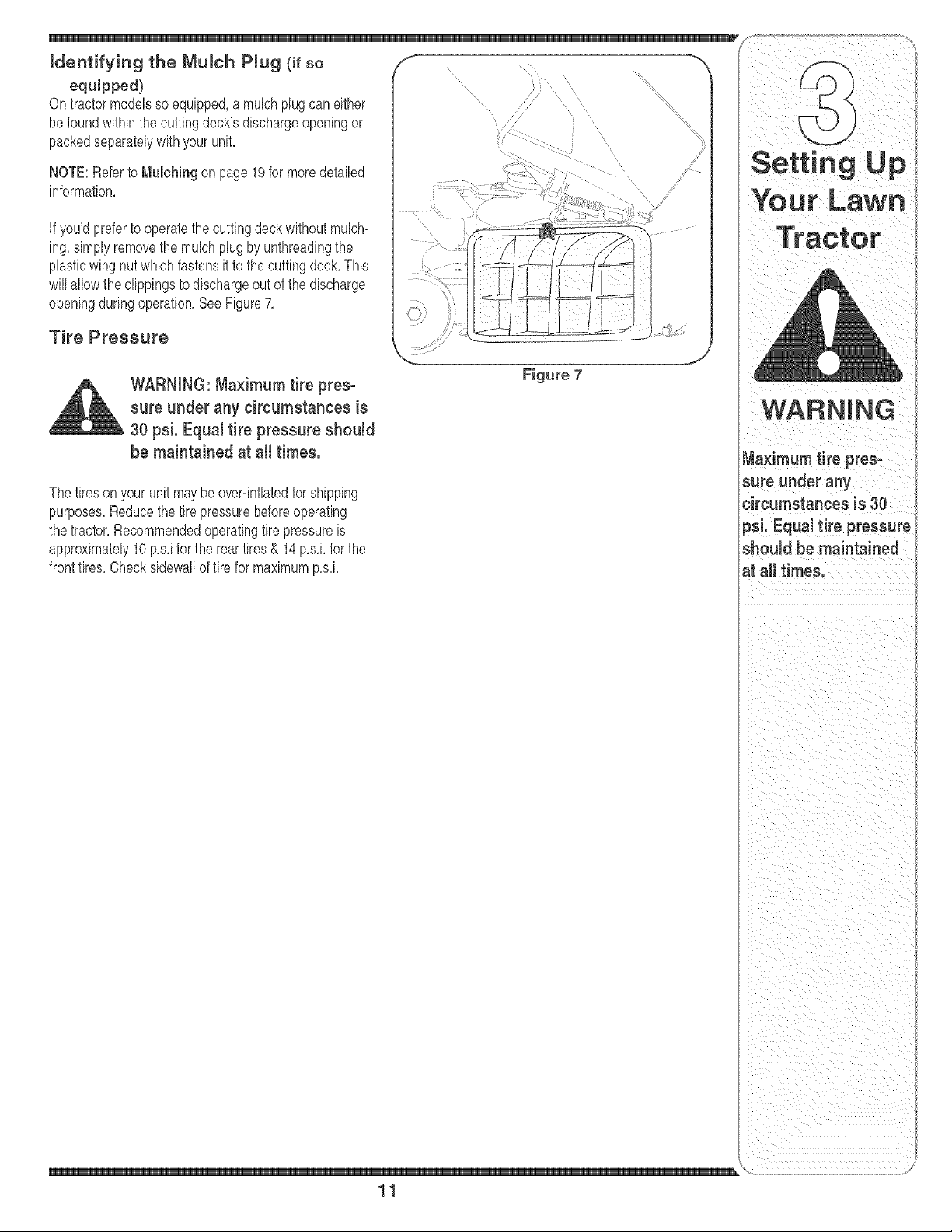
Attaching The Seat
1 Seatstyles varybytractormodeland therearethree
I rj <¢ dfferentsty es ava abe
[ StandardAd ostment
QuickAdiustment&
Setti nqUp • KnobAdius ment
,_ If theseat for yourtractordid notcomeattached,refer,to
YO U [' Lawr_ Figure4, Figure5, and Figure6 to kJentifyyourtractors
seatstyleandfollowthe applicableinstructionsbelowto
attachit,
Before operat ng this
machine, make sure
theseat e"gaged
t,eseatstop;stand
behind the machin e
and pull back on seat
sons, seats are either
fastened to the tractor
backward to the pivot
models so equipped)
i •
Figure 4
NOTE:Forshippingreasons,seatsare eitherfastened
to the tractorseat'spivot bracketwith a plastictie,or
mountedbackwardto the pivotbracket,In eithercase,
freethe seat form its shippingpositionand removethe
twohex screws(or knobs,on modelsso equipped)from
the bottomof seatbeforeproceedingwithapplicable
instructionsbelow,
Standard Adjustment Seat
1, Positionthe shoulderscrews(foundonthe baseof the
seat)insidethe slot openingsin the seatpivotbracket,
Figure4,
2, Slide theseatslightlyrearwardin the seatpivot
bracket,liningupthe rear slots in the pivotbracket
withthe remainingtwo holesinthe seat'sbase,
3, Selectdesiredpositionforthe seat,andsecurewith
the two hexscrewsremovedearlier,SeeFigure4,
Quick Adjustment Seat
NOTE:If yourseatwasshippedmountedbackwardson
the seatpivot bracket,pull outthe tab foundonthe seat
stopandholdit open whileslidingthe seatoffthe seat
pivotbracket,SeeFigure5,
Figure 5
1, Line up the plasticseatspacerswith the slotsin seat
pivotbracket,
2, Slide seat in until frontseat spacerengagesthe seat
stop,See Figure5,
WARNING: Before operating this
machine, make sure the seat is
engaged in the seat stop, stand
behind the machine and putl back
on seat until fully engaged into
stop.
Knob Adjustment Seat
1, Positionthe shoulderscrews(foundonthe baseof the
seat)insidethe slot openingsin the seatpivotbracket,
Figure6,
2, Slide theseatslightlyrearwardin the seatpivot
bracket,liningupthe rear slots in the pivotbracket
withthe remainingtwo holesinthe seat'sbase,
3, Selectdesiredpositionforthe seat,andsecurewith
10
equipped)
On tractormodelsso equipped,a mulch plugcan either
be foundwithinthe cuttingdeck'sdischargeopeningor
packedseparatelywithyour unit,
NOTE:Refer to Mulching on page19for moredetailed
information,
if you'dpreferto operatethe cuttingdeck withoutmulch=
ing, simplyremovethe mulch plugby unthreadingthe
plasticwing nutwhichfastensit to the cuttingdeck,This
will allowthe clippingsto dischargeout of the discharge
openingduringoperation,SeeFigure7,
Tire Pressure
WARNING: Maximum tire pres-
sure under any circumstances is
30 psi. Equal tire pressure should
be maintained at all times.
Figure 7
The tires on your unitmaybeover=inflatedfor shipping
purposes,Reducethe tirepressurebeforeoperating
the tractor,Recommendedoperatingtire pressureis
approximately10p,s,ifor the reartires& 14p,s,i,for the
fronttires,Checksidewallof tirefor maximump,s,i,
circumstances is 30
psi. Equal tire pressure
should be maintained
at all times.
\
11

inthis manualto the
f
Know Your Lawn Tractor
i •
\\
\
ii
Figure 8 tif so equipped
A SpeedControlLever/ParkingBrake E ThrottleControlLever
B Clutch-BrakePedal F ignitionSwitchModule
C ShiftLever G DeckLift Lever
D ChokeControlt H PTO(Blade Engage)Lever
NOTE:Anyreferencein this manualto the RIGHTor LEFTside of the tractoris observedfromoperatorsposition,
12
the wayforward,the chokecontrolalso,Whenset in a
givenposition,the throttlewill maintaina uniformengine
speed,SeeFigure9,
IMPORTANT:Whenoperatingthetractorwiththe cutting
deckengaged,be certainthatthe throttleleveris always
inthe FAST(rabbit)position,
Choke Control
Onsomemodels,movingthe
throttleleverallthe wayforward
activatestheengine'schoke
control Onall othermodels,the
lk
chokecontrolcan be foundon
the left side of thedash panel
andis activatedby pullingthe
knoboutward,Activatingthe
chokecontrolclosesthe choke
plateon the carburetorand aids instartingthe engine,
Referto Starting The Engine on page16of this manual
for detailedstartinginstructions,
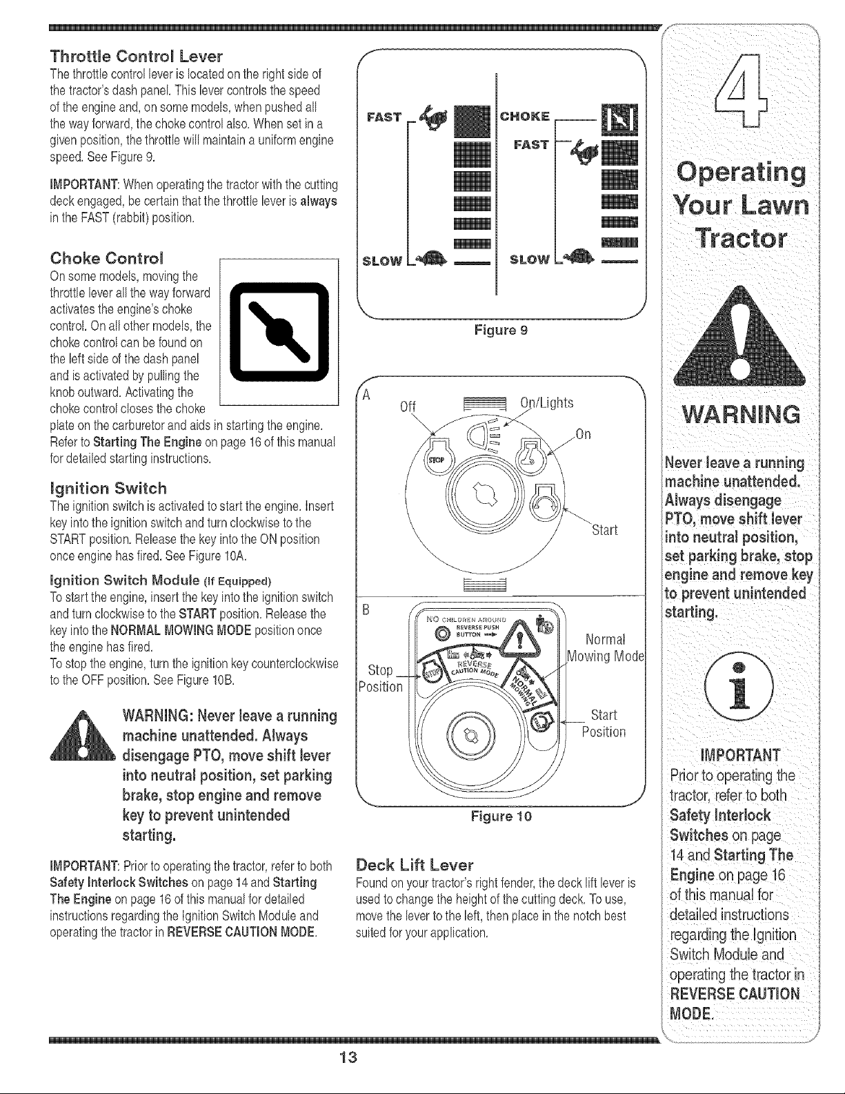
mgnition Switch
Theignitionswitchis activatedto startthe engine,Insert
keyintothe ignitionswitchand turnclockwisetothe
STARTposition,Releasethe key intothe ON position
onceengine hasfired,See FigureIOA,
Ignition Switch Module (mrEquipped)
Tostartthe engine,insertthe keyintothe ignitionswitch
andturnclockwiseto theSTARTposition,Releasethe
keyintothe NORMALMOWINGMODEpositiononce
the enginehasfired,
Tostop the engine,turnthe ignitionkeycounterclockwise
to the OFFposition,SeeFigurelOB,
WARNING: Never leave a running
machine unattended. Always
disengage PTO, move shift lever
into neutral position, set parking
brake, stop engine and remove
key to prevent unintended
starting.
IMPORTANT:Priorto operatingthe tractor,referto both
Safety hterlock Switches on page 14and Starting
The Engine on page16 of thismanualfordetailed
instructionsregardingthe IgnitionSwitchModuleand
operatingthetractorin REVERSECAUTIONMODE,
FAST
SLOW
J
Figure 9
f
A
Off l/Lights
\
\
)sition
Normal
Mode
Start
Position
Figure 10
J
Deck Lift Lever
Foundon yourtractor'srightfender,the deck lift leveris
usedto changethe heightof thecuttingdeck,To use,
movethe leverto the left, thenplace in the notchbest
suitedfor yourapplication,
13
machine unattended.
A ,vaysd sengage
PTO,move Shift lever
into neutral position,
set parking brake, stop
engine and remove key
operating the tractor in
REVERSE CAUTION
NOTE:Theparking
brakemustbesetifthe
operatorleavestheseal
withtheenginerun-
NOTE:ThePTO(Blade
Engage)levermustbe
inthedisengaged(PTO
OFFtpositionwhen
startingtheengine,
IMPORTANT
Neverforcetheshift
lever.Doingso may
resultinserious
damagetothetractor's
transmission.
NUET_L
REVER_E
,,.. j
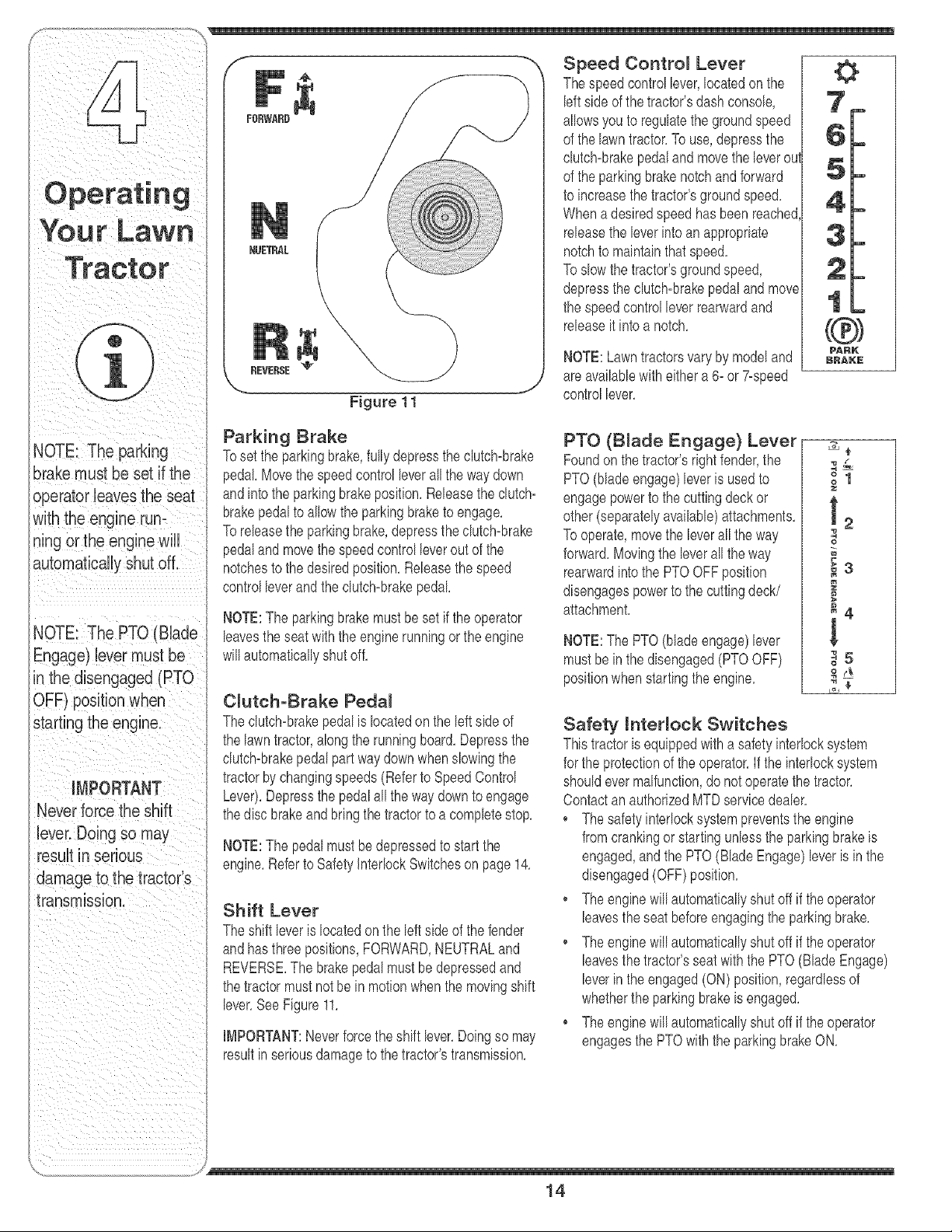
Figure 11
Parking Brake
Toset the parkingbrake,fullydepressthe clutch_brake
pedal Movethe speedcontrol leverallthe way down
andintothe parkingbrakeposition,Releasethe clutch_
brakepedalto allowthe parkingbraketo engage,
Toreleasethe parkingbrake,depressthe clutch_brake
pedaland movethe speedcontrolleverout of the
notchesto the desiredposition,Releasethe speed
controlleverand the clutch_brakepedal
NOTE:The parkingbrakemustbeset if theoperator
leavestheseat with the enginerunningor theengine
willautomaticallyshut off,
CJutch-Brake Pedal
Theclutch_brakepedalis locatedon the left side of
the lawntractor,alongthe runningboard,Depressthe
clutch_brakepedalpart waydownwhenslowingthe
tractorby changingspeeds (Referto SpeedControl
Lever),Depressthe pedalall thewaydownto engage
thedisc brakeand bringthe tractorto a completestop,
NOTE:The pedalmustbedepressedto startthe
engine,Referto SafetyInterlockSwitcheson page 14,
Shift Lever
Theshift leveris locatedon the left sideof thefender
andhasthree positions,FORWARD,NEUTRALand
REVERSE,The brakepedal mustbedepressedand
thetractor mustnotbe in motionwhenthe movingshift
lever,SeeFigure11,
IMPORTANT:Neverforcetheshift lever,Doingso may
resultinseriousdamageto the tractor'stransmission,
Speed Contro_ Lever
Thespeedcontrollever,locatedon the
leftside of the tractor'sdashconsole,
allowsyouto regulatethegroundspeed
of the lawntractor,To use,depressthe
clutch-brakepedalandmovethe leverou
of the parkingbrakenotchand forward
to increasethe tractor'sgroundspeed,
Whena desiredspeedhas beenreached
releasethe leverintoan appropriate
notchto maintainthatspeed,
Toslow the tractor'sgroundspeed,
depressthe clutch-brakepedal and mow
the speedcontrol leverrearwardand
releaseit intoa notch,
NOTE:Lawntractorsvaryby modeland
areavailablewith eithera 6_or 7-speed
controllever,
w
m
m
PTO (B_ade Engage} Lever
Foundon thetractor'sright fender,the
PTO(bladeengage)leveris usedto
engagepowerto the cuttingdeckor
other(separatelyavailable)attachments,
Tooperate,movethe leverall the way
forward,Movingthe leverallthe way
rearwardintothe PTOOFFposition
disengagespowerto the cuttingdeck/
attachment,
NOTE:The PTO(bladeengage)lever
mustbe in the disengaged(PTOOFF)
positionwhenstartingthe engine,
PARK
BAAKr'
=o
0
_3
_4
!
_5
0
8_
Safety hterJock Switches
Thistractoris equippedwitha safetyinterlocksystem
for theprotectionof the operator,If the interlocksystem
shouldevermalfunction,donot operatethe tractor,
ContactanauthorizedMTDservicedealer,
Thesafety interlocksystempreventstheengine
fromcrankingor startingunlessthe parkingbrakeis
engaged,and the PTO(BladeEngage)leveris inthe
disengaged(OFF)position,
, Theenginewill automaticallyshut off if theoperator
leavestheseat beforeengagingthe parkingbrake,
, Theenginewill automaticallyshut off if theoperator
leavesthetractor'sseat withthe PTO(BladeEngage)
leverin the engaged(ON) position,regardlessof
whetherthe parkingbrakeis engaged,
• Theenginewill automaticallyshut off if theoperator
engagesthe PTOwiththe parkingbrakeON,
/
14
ModeJs with Reverse Caution Mode
Withthe ignitionkeyin the NORMALMOWING
position,the enginewill automaticallyshutoff if the
PTO(Blade Engage)leveris movedintothe engaged
(ON) positionwith the shift leverin Reverse,
WARNING: Do not operate the
tractor if the interlocksystem
is malfunctioning. This system
was designed for your safety and
protection.
Reverse Caution Mode (if Equipped)
WARNING: Use extreme caution
white operating the tractor in
the REVERSE CAUTION MODE.
Nways took down and behind
before and white backing. Do not
operate the tractor when children
or others are around. Stop the
tractor immediately if someone
enters the area.
TheREVERSECAUTIONMODEpositionof the key
switchmoduleallowsthetractorto beoperatedin
reversewiththe blades(PTO)engaged,
IMPORTANT:Mowingin reverseis notrecommended,
Touse the REVERSECAUTIONMODE:
IMPORTANT:TheoperatorMUSTbe seatedin the
tractorseat,
1, Start the engineas instructedon page 16under
Starting The Engine,
2, Turnthe keyfromthe NORMALMOWING(Green)
positionto the REVERSECAUTIONMODE(Yellow)
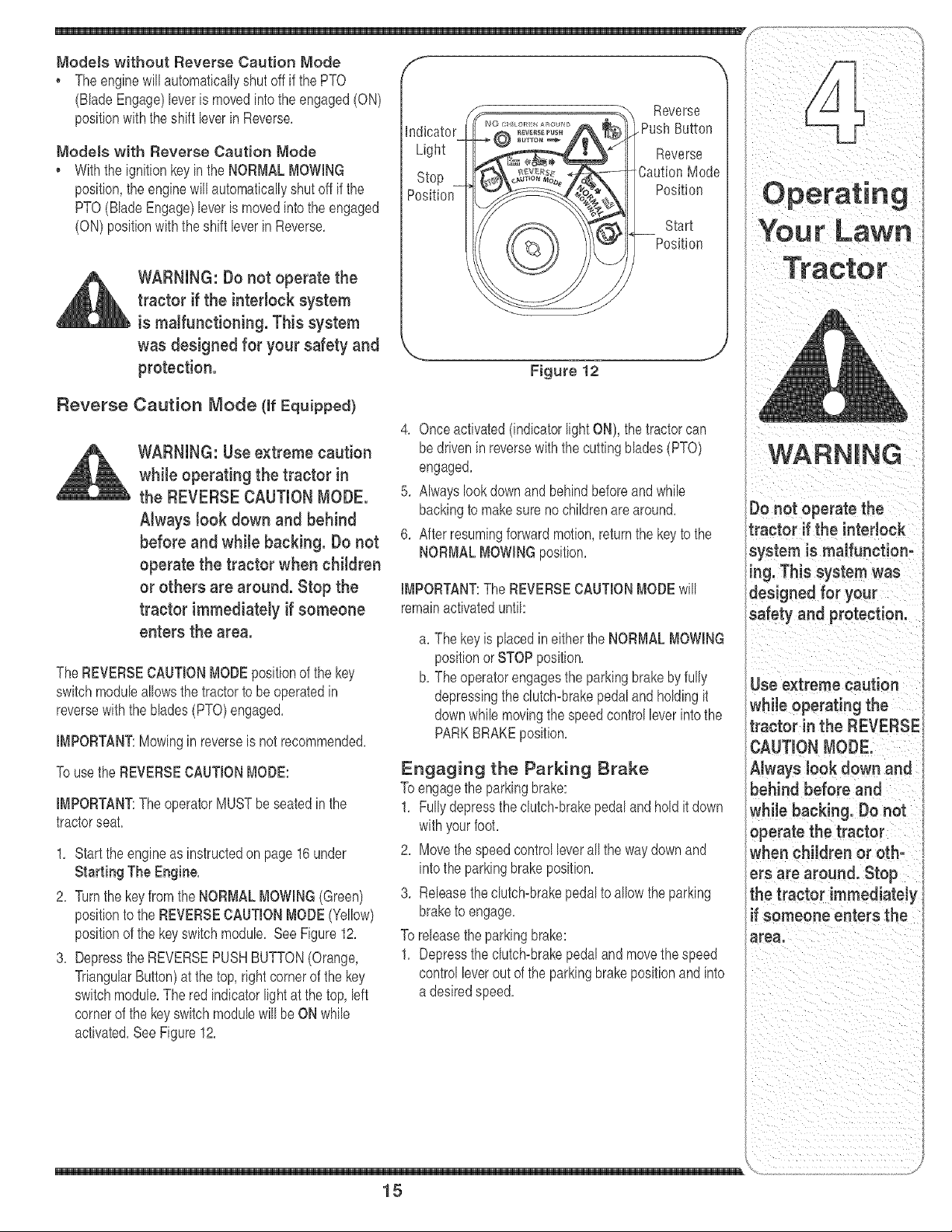
positionof the keyswitchmodule, SeeFigure12,
3, Depressthe REVERSEPUSHBUTTON(Orange,
TriangularButton)at the top,rightcornerof the key
switchmodule,The red indicatorlightat thetop, left
cornerof the keyswitchmodulewill be ON while
activated,See Figure12,
Stop
Position
Position
Start
Position
Figure 12
,J
4, Onceactivated(indicatorlightON), the tractorcan
be drivenin reversewiththecutting blades(PTO)
engaged,
5, Alwayslookdownandbehindbeforeandwhile
backingto makesure nochildrenarearound,
6, After resumingforwardmotion,returnthe key to the
NORMALMOWINGposition,
IMPORTANT:The REVERSECAUTIONMODEwill
remainactivateduntih
a, The key is placedineitherthe NORMALMOWING
positionor STOPposition,
b, The operatorengagesthe parkingbrakeby fully
depressingthe clutch=brakepedalandholdingit
downwhile movingthe speedcontrolleverintothe
PARKBRAKEposition,
Engaging the Parking Brake
Toengagethe parkingbrake:
1, Fullydepressthe clutch=brakepedaland holdit down
withyourfoot,
2, Move thespeedcontrolleverall the waydownand
into theparkingbrakeposition,
3, Releasethedutch=brakepedal to allowthe parking
braketo engage,
To releasetheparkingbrake:
1, Depressthe clutch=brakepedaland movethe speed
controlleverout of the parkingbrakepositionand into
a desiredspeed,
15
=aution
while operating the
tractor in the REVERSE
Always look down and
behind before and
whi!e back!rig, Donot
OPerate the tractor
when children or oth=
erS are around. Stop
the tractor immediately
if someone enters the
Setting the Cutting Height
1, Selectthe heightpositionof the cuttingdeckby
placingthe deck rift leverinany of the six different
cuttingheightnotchesonthe rightside of the fender,
2, Adjustthe deckwheels,if equipped,so thattheyare
between1A-inchand 1/2-inchabovethe groundwhen
the tractoris on a smooth,flat surfacesuch as a
driveway,
WARNING: Keep hands and feet
away from the discharge open°
ing of the cutting deck.
NOTE:On modelsso equipped,the deckwheelsare an
anti:scalpfeatureof thedeckandare notdesignedto
supportthe weightof the cuttingdeck,
Referto Levelingthe Deck on page20of this manual
for moredetailedinstructionsregardingvariousdeck
adiustments,
Starting the Engine
WARNING: Do not operate the
tractor if the interlocksystem is
malfunctioning. This system was
designed for your safety and
protection.
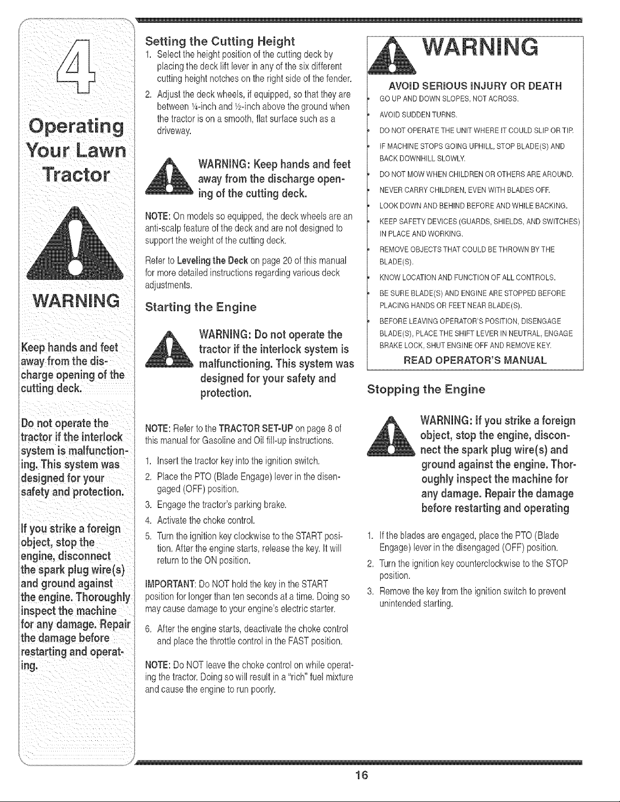
AVOID SERIOUS INJURY OR DEATH
GO UPAND DOWN SLOPES,NOT ACROSS,
AVOIDSUDDENTURN&
DO NOT OPERATETHE UNITWHERE IT COULDSLIP ORTIR
IFMACHINE STOPSGOING UPHILL,STOP BLADE(S)AND
BACK DOWNHILLSLOWLY
DO NOT MOWWHEN CHILDRENOR OTHERS AREAROUND,
NEVER CARRYCHILDREN,EVENWITH BLADES OFE
LOOK DOWNAND BEHINDBEFOREAND WHILE BACKING.
KEEP SAFETYDEVICES(GUARDS,SHIELDS,AND SWITCHES
IN PLACEAND WORKING,
REMOVEOBJECTSTHATCOULDBE THROWNBYTHE
BLADE(S)_
KNOW LOCATIONAND FUNCTIONOF ALL CONTROLS.
BE SUREBLADE(S) AND ENGINEARESTOPPEDBEFORE
PLACINGHANDSORFEET NEAR BLADE(S)_
BEFORE LEAVINGOPERATOR'SPOSITION,DISENGAGE
BLADE(S), PLACETHE SHIFT LEVER IN NEUTRAL,ENGAGE
BRAKE LOCK, SHUT ENGINEOFF AND REMOVEKEY_
READ OPERATOR'S MANUAL
Stopping the Engine
Do not operate the
tractor if the interlock
system is malfunction-
ing. This system was
designed for your
safety and protection.
ifyou strike a foreign
object, stop the
engine, disconnect
the spark plug wire(s)
and ground against
the engine. Thoroughly
inspect the machine
for any damage. Repair
the damage before
restarting and operat-
ing.
NOTE:Referto the TRACTORSET-UPon page8 of
thismanualfor Gasolineand Oil fill-upinstructions,
1, insertthe tractorkeyinto the ignitionswitch,
2, Placethe PTO(BladeEngage)leverin the disen-
gaged(OFF)position,
3, Engagethetractor'sparkingbrake,
4, Activatethe chokecontrol
5, Turnthe ignitionkeyclockwiseto the STARTposi-
tion,Afterthe enginestarts, releasethe key,it will
returnto theON position,
iMPORTANT:Do NOT holdthe keyin the START
positionfor longerthanten secondsat a time, Doingso
maycausedamageto yourengine'selectricstarter,
6, After theenginestarts, deactivatethechokecontrol
andplacethe throttlecontrolin theFASTposition,
NOTE:Do NOTleavethe chokecontrolon while operat-
ingthe tractor,Doingso will result in a "rich" fuelmixture
andcausethe engineto run poorly,
WARNING: if you strike a foreign
object, stop the engine, discon-
nect the spark plug wire(s} and
ground against the engine. Thor°
ougNy inspect the machine for
any damage. Repair the damage
before restarting and operating
1, If the bladesare engaged,placethe PTO(Blade
Engage)leverin the disengaged(OFF) position,
2, Turnthe ignitionkey counterclockwiseto the STOP
position,
3, Removethe keyfromthe ignitionswitchto prevent
unintendedstarting,
/
16
WARNING:Donotleavetheseat
of thetractorwithoutfirst plac-
ing the PTO (Blade Engage} lever
in the disengaged (OFF) posi-
tion, depressing the brake pedal
and engaging the parking brake.
if leaving the tractor unattended,
also turn the ignition key off and
remove the key.
Nways look down and behind
before and whiJe backing up to
avoid a back-over accident.
1, Depressthe brakepedalto releasethe parkingbrake
andlet the pedalup,
2, Movethe throttleleverintothe FAST(rabbit)position,
3, Placetheshift leverin eitherthe FORWARDor
REVERSEposition,
IMPORTANT:Do NOTusethe shift leverto changethe
directionof travelwhenthe tractoris in motion,Always
usethe brakepedalto bringthe tractorto a complete
stopbeforeshifting,
4, Releasethe parkingbrakeby depressingthe clutch-
brakepedaland positioningthe speedcontrolleverin
desiredposition,
IMPORTANT:First-timeoperatorsshouldusespeed
positions1 or2, Becomecompletelyfamiliarwiththe
tractor'soperationand controlsbeforeoperatingthe
tractorin higherspeed positions,
5, Releaseclutch-brakepedalslowlyto put unitinto
motion,
6, The lawntractor is broughtto a stop bydepressing
the clutch-brakepedal
place the shift lever in neutral,
engage the parking brake, shut
engine off and remove the key.
IMPORTANT:Whenstoppingthe tractorforany reason
whileon a grasssurface,always:
1, Placethe shift leverin neutral,
2, Engagethe parkingbrake,
3, Shutengineoff andremovethe key,
Doingso will minimizethe possibilityof havingyourlawn
"browned"by hot exhaustfromyourtractor'srunning
engine,
If unit stalls withspeedcontrolin high speed,or if unit
will notoperatewith speedcontrol leverin a lowspeed
position,proceedas follows:
1, Placeshift leverin NEUTRAL,
2, Restartengine,
3, Placespeedcontrolleverin highestspeedposition,
4, Releaseclutch=brakepedalfully,
5, Depressclutch=brakepedal,
6, Placespeedcontrolleverin desiredposition,
7, Placeshift leverin eitherFORWARDor REVERSE,
andfollownormaloperatingprocedures,
17
WARNING
Avoid sudden starts,
ex=cessive speed and
sudden stops.
Do not leavethe seat
of the tractor without
first placing the PTO
(Blade Engage) lever in
the disengaged (OFF)
position, depressing
the brake pedal and
engaging the parking
brake, ff leaving the
tractor unattended,
also turn the ignition
key off and remove the
key.
Always look down
and behind before
and while backing up
to avoid a back-over
accident.
WARNING
Do not mow on inclines
with a slope in excess
of 15 degrees (a rise
of approximately 2-1/2
feet every 10feet}, "[he
tractor could overturn
and cause serious
injury,
fi help avoid blade
ntact or a thrown
ject injury, keep
bystanders, helpers,
;hildren and pets at
east 75 feet from the
_achine while it is in
_peration, Sto p ma=
,'hine if anyone enters
the area,
Referto the SLOPEGAUGEon page3 to helpdetep
mineslopeswhereyou mayoperatethe tractorsafely,
WARNING: Do not mow on
inclines with a s!ope in excess
of !5 degrees (a rise of approxi-
mately 2-1/2 feet every 10 feet}.
The tractor could overturn and
cause serious injury.
• Mow up anddownslopes,NEVERacross,
• Exerciseextremecautionwhenchangingdirection
onslopes,
• Watchfor holes,ruts,bumps,rocks, or otherhidden
obiects,Uneventerraincouldoverturnthe machine,
Tall grasscan hideobstacles,
• Avoidturns whendrivingona slope,Ifa turn must
be made,turn downthe slope,Turningup a slope
greatlyincreasesthechanceof a rollover,
, Avoidstoppingwhendrivingup a slope, If it is
necessaryto stop whiledrivingupa slope, start up
smoothlyandcarefullyto reducethe possiNlityof
flippingthetractoroverbackward,
Engaging the Blades
Engagingthe PTO(BladeEngage)transferspowerto
thecutting deckor other(separatelyavailable)attach=
ments,To engagethe blades,proceedas follows:
1, Movethe throttlecontrolleverto the FAST(rabbit)
position,
2, Graspthe PTO(BladeEngage)leverand pivotit all
the wayforwardinto theengaged(ON) position,
3, Keepthe throttleleverin the FAST(rabbit)position
for the mostefficientuseof the cuttingdeckor other
(separatelyavaUable)attachments
iMPORTANT:Models with ReverseCaution Node:
Theenginewill automaticallyshut off if the PTOis
engagedwiththe shift leverin positionfor reversetravel
withthe ignitionkeyinthe NORMALMOWINGposition,
Models without ReverseCaution Node:
The PTO(BladeEngage)levermustbein the disen=
gaged(OFF)positionwhenstartingthe engine,when
travelingin reverse,and if the operatorleavesthe seat,
Referto SafetyInterlockSwitcheson page 14,
Using the Deck Lift Lever
Toraisethe cuttingdeck, movethe deck lift leverto the
left, thenplace it inthe notch bestsuited for yourapplica-
tion,Referto SettingThe CuttingHeightearlierin this
section,
Mowing
WARNING: To help avoid blade
contact or a thrown object injury,
keep bystanders, hetpers, children
and pets at least 75 feet from the
machine while it is in operation.
Stop machine if anyone enters the
area.
Thefollowinginformationwill be helpfulwhenusingthe
cuttingdeckwith yourtractor:
WARNING: Plan your mowing
pattern to avoid discharge of
materials toward roads, sidewalks,
bystanders and the like. Also,
avoid discharging material against
a walt or obstruction which may
cause discharged material to
ricochet back toward the operator.
Do not mowat high groundspeed,especiallyif a
mulchkit or grasscollectoris installed,
For bestresultsit is recommendedthatthe firsttwo
lapsbe cut with the dischargethrowntowardsthe
center,After thefirst twolaps,reversethe directionto
throwthe dischargeto the outsidefor the balanceof
cutting,Thiswill givea betterappearanceto the lawn,
, Do notcut thegrasstoo short,Shortgrassinvites
weedgrowthand yellowsquicklyin dryweather,
, Mowingshouldalwaysbedonewiththeengineat full
throttle,
, Underheavierconditionsit may be necessarytogo
backover thecut areaa secondtimeto get a clean
cut,
Y
18
Mulching (IfEquipped)
Selectmodelscome equipped,witha mu{chkit,which
incorporatesspecialb{ades,alreadystandardon the
tractor,ina processof recirculatinggrassclippings
repeatedlybeneaththecutting deck,The ultra-fine
clippingsarethenforced backinto thelawnwherethey
actas a naturalfertilizer,
Observethe followingpointsfor the best resultswhen
mulching:
• Neverattemptto mulchif the lawnis damp,Wet grass
tendsto stick to the undersideof the cuttingdeck
preventingpropermulchingof the clippings,
• Do NOTattemptto mulch morethan 1/3the total
heightof thegrassor approximately1-1/2inches,
Doingso will causethe clippingsto clumpup beneath
the deck and not bemulchedeffectively,
, Maintaina slowgroundspeedto allowthe grass
clippingsmoretime to effectivelybe mulched,
, Alwayspositionthe throttlecontrol leverinthe FAST
(rabbit)positionand allowit to remaintherewhile
mowing,Failingto keepthe engineat full throttle
placesstrainonthe tractor'sengineand does not
allowthe bladesto properlymulchgrass,
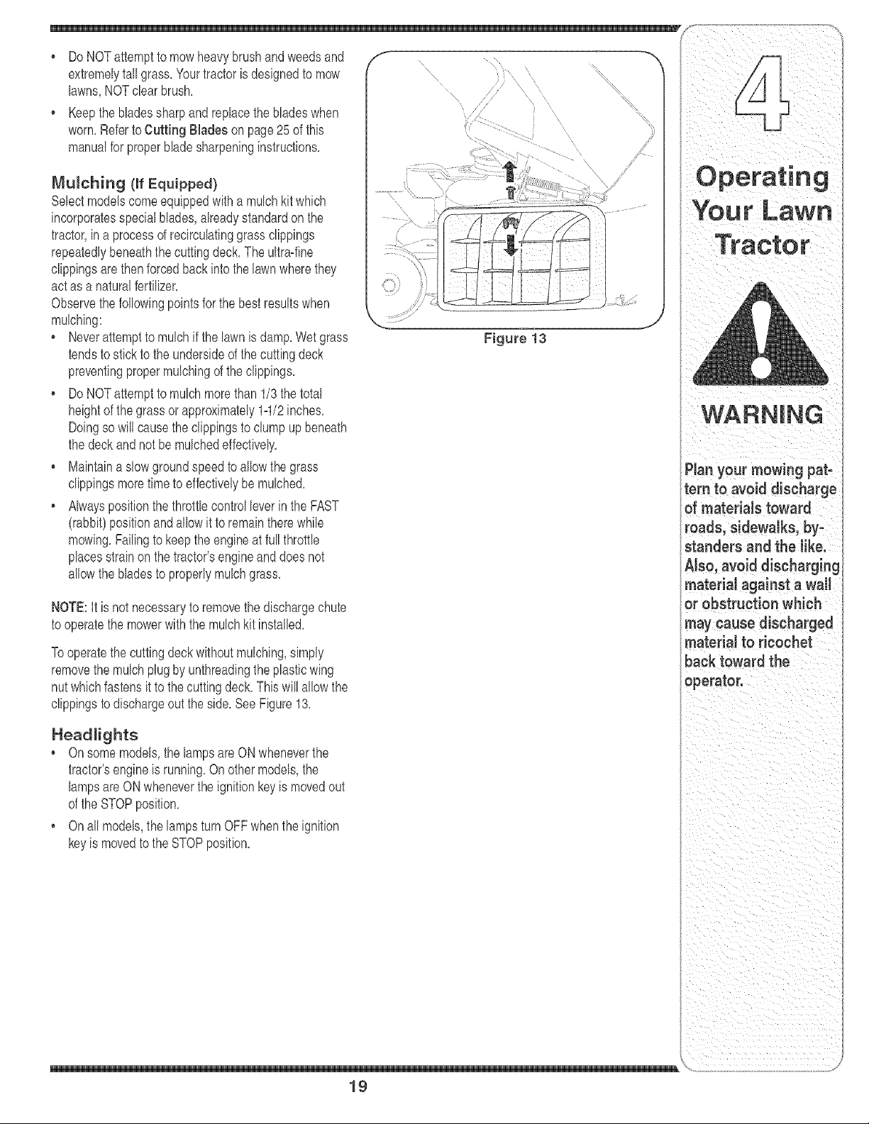
NOTE:It is not necessaryto removethe dischargechute
to operatethe mowerwiththe mulchkit installed,
Tooperatethe cuttingdeckwithoutmulcNng,simply
removethe mulch plug by unthreadingthe plasticwing
nut whichfastensit to thecuttingdeck,Thiswill allowthe
clippingsto dischargeout the side,See Figure13,
Headlights
• On some models,the lampsare ON wheneverthe
tractor'sengineis running,On other models,the
lampsareON wheneverthe ignitionkeyis movedout
of the STOPposition,
, Onall models,the lampsturn OFFwhenthe ignition
keyis movedto the STOPposition,
Figure 13
19
tern to avoid discharge
of materials toward
roads, sidewalks, by-
standers and the like.
Also,avoiddischarging
material against a wail
or obstruction which
may cause discharged
material to ricochet
back toward the
operator.
!g
IrLaw
WARNING
Never attempt to
make any adjust=
merits while the
engine is running,
except where speci-
fied in the operator's
manual
_ever attempt to
_djuat the brakes
while the engine
is running. Nways
disengage PTO, move
shift lever into neutraJ
position, atop engine
and remove key to
prevent unintended
starting.
Figure 14
Figure 15
WARNING: Never attempt to
make any adjustments whiJe
the engine is running, except
where specified in the operator's
manual.
Leveling the Deck
NOTE:Checkthe tractor'stire pressurebeforeperform-
ingany deck levelingadiustments,Referto Tires on
page24 for informationregardingtire pressure,
Front To Rear
The front of the cuttingdeckis supportedbya stabilizer
barthatcan adiustedto levelthe deckfrom front to rear,
The front of the deck shouldbebetween1/4-inchand
3/8-inchlowerthanthe rear of thedeck, Adiustif
necessaryas follows:
thatit is parallelwith the tractor,
2, Measurethe distancefromthe front of the bladetip to
the groundand the rearof the bladetip to the ground,
Thefirst measurementtakenshouldbe between
1/4" and3/8" less thanthe second measurement,
Determinethe approximatedistancenecessaryfor
properadiustmentandproceed,if necessary,to the
nextstep,
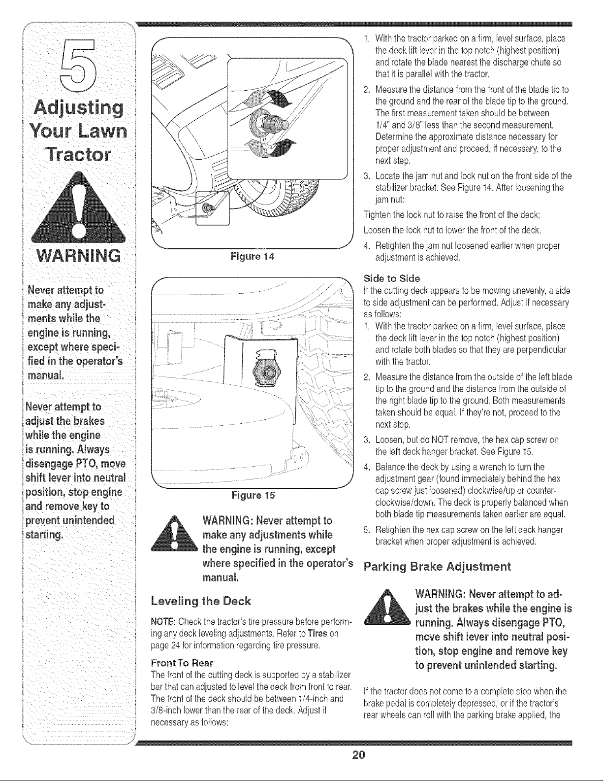
3, Locatetheiam nutand lock nut onthe front sideof the
stabilizerbracket,SeeFigure14,Afterlooseningthe
iam nut:
Tightenthe lock nutto raisethe frontof the deck;
Loosenthe lock nut to lowerthe frontof the deck,
4, Retightenthe iam nut loosenedearlierwhenproper
adiustmentis achieved,
Side to Side
If thecutting deckappearsto bemowingunevenly,aside
to sideadiustmentcan be performed,Adiustif necessary
as follows:
1, With thetractor parkedon a firm,levelsurface,place
the deck lift leverin the top notch(highestposition)
androtatebothbladesso that theyare perpendicular
withthe tractor,
2, Measurethe distancefromthe outsideof the left blade
tip to the groundand the distancefromtheoutsideof
the rightbladetipto the ground,Bothmeasurements
takenshouldbe equal If they'renot,proceedto the
nextstep,
3, Loosen,butdo NOTremove,the hexcap screwon
the left deck hangerbracket,See Figure15,
4, Balancethe deckby usingawrenchto turnthe
adiustmentgear(foundimmediatelybehindthe hex
capscrewiust loosened)clockwise/uporcounter-
clockwise/down,Thedeck is properlybalancedwhen
both bladetip measurementstakenearlierareequal,
5, Retightenthe hex capscrewon the leftdeckhanger
bracketwhenproperadiustmentis achieved,
Parking Brake Adjustment
,_ll, WARNING: Never attempt to ad-
just the brakes while the engine is
running. Always disengage PTO,
move shift lever into neutral posi-
tion, stop engine and remove key
to prevent unintended starting.
If thetractordoes notcometo a completestop whenthe
brakepedal iscompletelydepressed,or if thetractor's
rearwheelscanroll withthe parkingbrakeapplied,the
2O
brakeis in needof adiustment,The brakedisc can be
foundon the rightsideof the transmissionin the rearof
the tractor,Adiustif necessaryas follows:
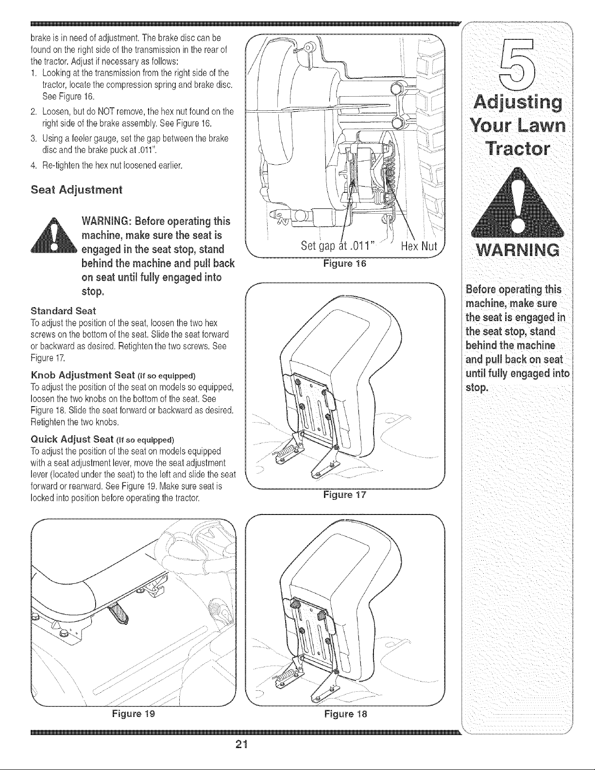
1, Lookingat thetransmissionfrom the rightside of the
tractor,locatethe compressionspringand brakedisc,
SeeFigure16,
2, Loosen,but do NOTremove,the hex nutfoundon the
rightsideof the brakeassembly,SeeFigure16,
3, Usinga feelergauge,setthe gap betweenthebrake
discandthe brakepuckat ,011",
4, Re=tightenthe hexnut loosenedearlier,
Seat Adjustment
_lj ARNING: Before operating this
machine, make sure the seat is
engaged in the seat stop, stand
behind the machine and pull back
on seat until fully engaged into
stop.
Standard Seat
Toadiust the positionof the seat,loosenthe two hex
screwson the bottomof the seat,Slidethe seatforward
or backwardas desired,Retightenthe two screws,See
Figure17,
Knob Adjustment Seat (if so equipped)
Toadiust the positionof the seaton modelsso equipped,
loosenthe two knobs on the bottomof the seat, See
Figure18, Slidethe seatforwardor backwardas desired,
Retightenthe two knobs,
Quick Adjust Seat (mrso equipped)
Toadiust the positionof the seaton modelsequipped
witha seatadiustmentlever,movetheseatadiustment
lever(locatedunder theseat)to the left and slidethe seat
forwardor rearward,SeeFigure19,Makesureseatis
lockedintopositionbeforeoperatingthe tractor,
f
Set gap .011
Figure 16
Hex Nut
Figure 17
machine, make sure
the seat is engaged in ,I
the seat stop, stand }
behind the machine ;
and pull back on seat }
until fully engaged into i
stop.
zJ-•'•• ." ZY
Figure 19 Figure 18
21
Maintaining
Your Lawn
Tractor
WARNING: Before performing
any maintenance or repairs,
disengage PTO, move shift Jever
into neutral position, set parking
brake, stop engine and remove
key to prevent unintended
starting.
Engine
Referto the Engine OperatodOwner Manualfor
engine maintenance instructions.
Checkengine oil level beforeeachuseas instructed
in the EngineOperator/OwnerManualpackedwith your
unit,Follow the instructionscarefully.
Changing Engine Oil
NOTE:Dependingon the engine modelfoundon your
tractor,it may be necessaryto removethe tractor'sside
panelinorderto replacethe oilfilter (if so equipped),
Fordrainingoil fromthe engine'scrankcaseof select
modeltractors,a plasticoildrain sleeveis packedwith
thisOperator'sManual Todrainthe oil, proceedas
follows:
1, Unscrewthe oil fill capand removethe dipstickfrom
the oil fill tube,
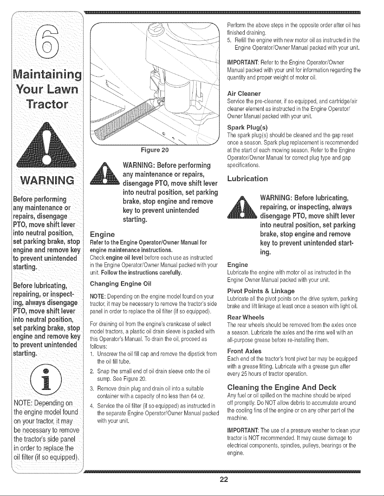
2, Snapthe smallendof oil drain sleeveontothe oil
sump,See Figure20,
3, Removedrain plugand drain oil intoa suitable
containerwitha capacityof no lessthan 64oz,
4, Servicethe oilfilter (if soequipped)as instructedin
the separateEngineOperator/OwnerManualpacked
withyourunit,
Performthe abovestepsin theoppositeorderafteroil has
finisheddraining,
5, Refillthe enginewith newmotoroilas instructedin the
EngineOperator/OwnerManualpackedwith your unit,
IMPORTANT:Referto the EngineOperator/Owner
Manualpackedwith yourunit for informationregardingthe
quantityand properweightof motoroil
Air Cleaner
Servicethe pre=cleaner,if so equipped,andcartridge/air
cleanerelementas instructedin the EngineOperator/
OwnerManualpackedwith your unit,
Spark PJug(s)
Thespark plug(s)shouldbecleanedand the gap reset
oncea season,Sparkplugreplacementis recommended
at the startof each mowingseason,Referto the Engine
OperatodOwnerManualfor correctplugtypeandgap
specifications,
Lubrication
WARNING: Before lubricating,
repairing, or inspecting,atways
disengage PTO, move shift lever
into neutrat position, set parking
brake, stop engine and remove
key to prevent unintended start-
ing.
Engine
Lubricatethe enginewith motoroil as instructedinthe
EngineOwnerManualpackedwith your unit,
Pivot Points & Linkage
Lubricateall the pivotpointson the drivesystem,parking
brakeand lift linkageat least oncea seasonwithlightoil
Rear WheeJe
The rearwheelsshouldberemovedfromthe axles once
a season,Lubricatethe axles and the rimswell with an
all=purposegreasebeforere=installingthem,
Front A×lee
Eachend of the tractor'sfrontpivotbarmay be equipped
witha greasefitting,Lubricatewitha greasegun after
every25 hoursof tractoroperation,
C_eaning the Engine And Deck
Anyfuel or oil spilledonthe machineshouldbewiped
off promptly,DoNOT allowdebristo accumulatearound
the coolingfins of the engine or on anyotherpart of the
machine,
IMPORTANT:The useof a pressurewasherto cleanyour
tractoris NOT recommended,It maycausedamageto
electricalcomponents,spindles,pulleys,bearingsor the
engine,
22
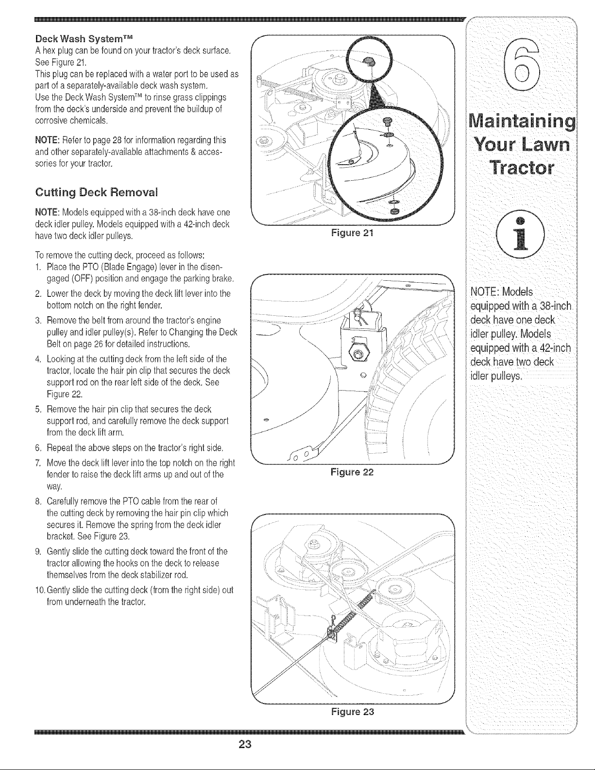
Deck Wash System TM
A hexplug can be foundonyourtractor'sdecksurface,
SeeFigure21,
Thisplugcan be replacedwith a water port to be used as
partof a separateIy_availabIedeckwashsystem,
Usethe DeckWash SystemTM to rinsegrasscIippbgs
fromthedeck'sundersideand preventthe buildupof
corrosivechemicals,
NOTE:Referto page 28 for informationregardingthis
andotherseparately-availableattachments& acces-
sorbs for yourtractor,
Cutting Deck Remova_
NOTE:Modelsequippedwith a 38-inchdeck haveone
deckidlerpulley,Modelsequippedwitha 42-bch deck
havetwo deckidler pulleys,
Toremovethe cuttingdeck, proceedas follows:
1, Placethe PTO(BladeEngage)leverin the disem
gaged(OFF)positionandengagethe parkingbrake,
2, Lowerthe deckby movingthedeck liftbver into the
bottomnotchon the rightfender,
3, Removethe beltfromaroundthe tractor'sengine
pulleyand idler pulby(s), RefertoChangingthe Deck
Belton page 26 for detailedinstructions,
4, Lookingat the cuttingdeckfromthe leftsideof the
tractor,locatethe hair pin clip thatsecuresthe deck
supportrodon the rear left sideof thedeck, See
Figure22,
5, Removethe hair pin clipthatsecuresthedeck
supportrod, and carefullyremovethe decksupport
fromthedeck liftarm,
6, Repeatthe abovestepson the tractor'srightside,
7, Movethe decklift bver intothe top notchon the right
fenderto raisethedeck lift arms up andout of the
way,
8, Carefullyremovethe PTOcabb fromthe rearof
the cuttingdeck by removingthe hair pin clipwhich
securesit, Removethe springfromthe deck idler
bracket,SeeFigure23,
9, Gentlyslidethe cuttingdecktowardthefront of the
tractorallowingthe hookson the deckto rebase
themselvesfromthedeck stabilizerrod,
10,Gentlyslidethe cuttingdeck(from the rightside)out
fromunderneaththetractor,
Figure 21
/
Figure 22
i
......
Figure 23
23
NOTE: Models
equippedwith a 38°inch
deck have one deck
idler pulley, Models
equippedwith a 42-inch
deck have two deck
idler pulleys.
Tires Jump Starting
Never exceed the
maximum inflation
)ressure shown on the
sidewall of the tire.
Batteries give off an
_xpiosive gas while
:harging. Charge bat-
tery in a well ventiJated
area and keep away
Froman open flame
or pilot light as on a
_ater heater, space
heater, furnace, clothes
dryer or other gas
appliances.
Always use a fuse with
the same amperage
capacity for replace-
meat.
WARNING: Never exceed the
maximum inflation pressure
shown on the sidewall of tire.
The recommendedoperatingtire pressureis:
Approximately10psifor the rear tires
, Approximately14psi for the fronttires
IMPORTANT:Referto the tire sidewallforexacttire
manufacturer'srecommendedormaximumpsi, Do not
overinflate,Uneventire pressurecouldcausethe cutting
deckto mow unevenly,
Battery
Thebatteryis sealedandis maintenance-free,Acid
levelscannotbe checked,
, Alwayskeepthe batterycablesandterminalsclean
andfreeof corrosivebuild-up,
, Aftercleaningthe batteryandterminals,apply a light
coatof petroleumielly or greaseto bothterminals,
• Alwayskeepthe rubberboot positionedoverthe
positiveterminalto preventshorting,
IMPORTANT:If removingthe batteryforany reason,
disconnectthe NEGATIVE(Black)wire fromit's terminal
first,followedbythe POSITIVE(Red)wire,When
re-installingthe battery,alwaysconnectthe POSITIVE
(Red)wire its terminalfirst, followedbythe NEGATIVE
(Black)wire,Becertainthat thewiresare connectedto
thecorrectterminals;reversingthemcould changethe
polarityandresultindamageto your engine'salternat-
ingsystem,
Charging
If thetractor hasnot beenput into usefor an extended
periodof time,chargethe batterywith anautomotive-
type 12-voltchargerfor a minimumof one hour at six
amps.
WARNING: Batteries give off an
explosive gas while charging.
Charge battery in a well venti°
lated area and keep away from
an open flame or pilot light as
on a water heater, space heater,
furnace, clothes dryer or other
gas appliances.
WARNING: When removing or
installingthe battery, follow
these instructions to prevent the
screwdriver from shorting against
the frame.
IMPORTANT:Neveriumpyourtractor'sdead batterywith
the batteryof a runningvehicle,
1, Connectend of oneiumpercableto the positive
terminalof thegoodbattery',thenthe otherendto the
positiveterminalof the deadbattery,
2, Connectthe otheriumpercableto the negative
terminalof thegoodbattery,thento the frame of the
unit with the dead battery.
WARNING: Failure to use this
procedure could cause sparking,
and the gas in either battery could
explode.
Cleaning
Cleanthe batteryby removingit fromthe tractorand
washingwitha bakingsodaand watersolution,If neces-
sary,scrapethe batteryterminalswitha wire brushto
removedeposits,Coatterminalsand exposedwiringwith
greaseor petroleumielly to preventcorrosion,
Battery Failures
Somecommoncausesfor batteryfailureare:
, incorrectinitialactivation • undercharging
, overcharging • corrodedconnections
, freezing
Thesefailures are NOTcovered by your tractor's
warranty.
Fuse
One20AMPfuseis installedin yourtractor'swiringhaF
hessto protectthe tractor'selecNcal systemfrom damage
causedby excessiveamperage,
If the electricalsystemdoes notfunction,or your tractor's
enginewill not crank,first checkto be certain that the fuse
has notblown,It can be foundunderthe hoodmounted
behindthe dashpanelon the rightside,
WARNING: Always use a fuse with
the same amperage capacity for
replacement.
y
24
Cutting Blades
WARNING:Besuretoshut
theengineoff, removeignition
key, disconnect the spark plug
wire(s) and ground against the
engine to prevent unintended
starting before removing the cut-
ting Made(s) for sharpening or
replacement. Protect your hands
by using heavy gloves or a rag to
grasp the cutting Made.
WARNING: Periodically inspect
the Made spindles for cracks or
damage, especially if you strike a
foreign object. Replace immedi-
ately if damaged.
Thebladesmaybe removedas follows,
1, Removethe deckfrombeneaththe tractor,(referto
CuttingDeckRemovalon page23) thengentlyflip
the deck overto exposeits underside,
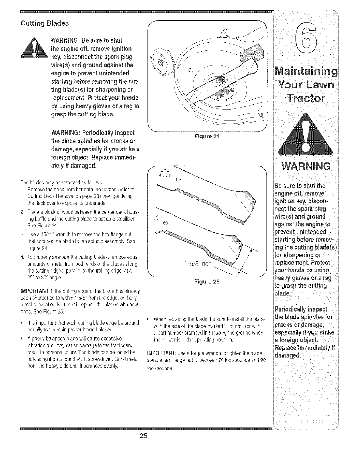
2, Placea blockof wood betweenthe centerdeck hous-
ingbaffleandthe cuttingbladeto act asa stabilizer,
SeeFigure24,
3, Use a 15/16"wrenchto removethe hexflangenut
thatsecuresthe bladeto thespindleassembly,See
Figure24,
4, Toproperlysharpenthe cutting blades,removeequal
amountsof metalfrom bothends of the bladesalong
the cuttingedges, parallelto the trailingedge,at a
25° to 30° angle,
IMPORTANT:If the cuttingedgeof the bladehasalready
beensharpenedto within 1 5/8" fromthe edge,or if any
metalseparationis present,replacethe bladeswith new
ones,SeeFigure25,
It is importantthat eachcuttingblade edge be ground
equallyto maintainproper bladebalance,
A poorlybalancedbladewill causeexcessive
vibrationand maycausedamageto thetractorand
resultinpersonaliniury,The bladecan betestedby
balancingit on a roundshaftscrewdriver,Grindmetal
fromthe heavysideuntil it balancesevenly,
Figure 24
1-5/8 inch .J
Figure 25
When replacingthe blade,be sure to installthe blade
with theside of the blade marked"Bottom" (or with
a part numberstampedinit) facing the groundwhen
the mower is inthe operatingposition,
IMPORTANT:Useatorquewrenchto tightenthe blade
spindlehex flangenutto between70foot-poundsand90
foot-pounds,
25
rig
Be sure to shut the ,
engineoff,remove
ignition key, discon_
nect the spark Plug
wire(s) and ground
against the engine to
prevent unintended
Your Lawn
WARNING
Be sure to shut the
engine off, remove ig-
nition key, disconnect
the spark pJugwire(s)
and ground against
the engine to prevent
unintended starting
before removingthe
beJt(s).
Avoid the possibility of
a pinching injury. Do
not place your fingers
an the idler spring or
be_een the belt and a
pulleywhile removing
the beJt.
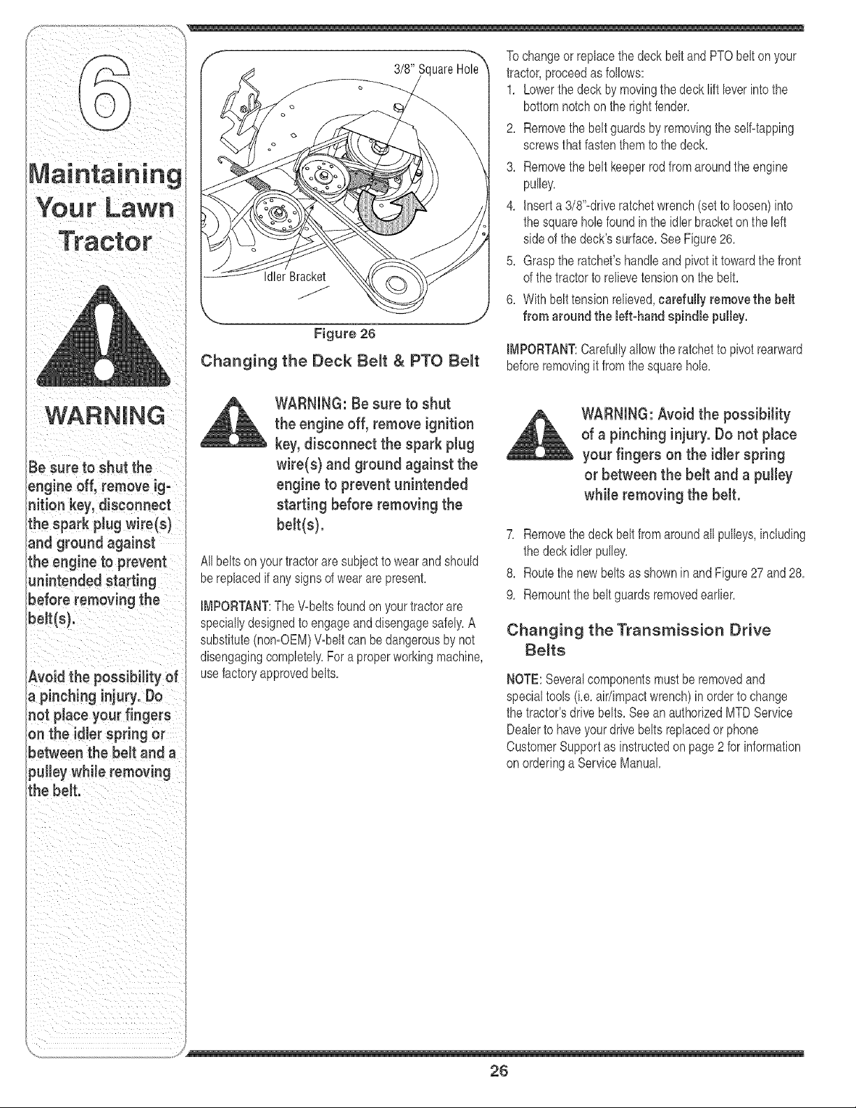
3/8" uareH01_'_
Figure 26
Changing the Deck Be_t & PTO BeNt
WARNING: Be sure to shut
the engine off, remove ignition
key, disconnect the spark plug
wire(s) and ground against the
engine to prevent unintended
starting before removing the
belt(s).
Allbeltson yourtractorare subiectto wearand should
bereplacedif anysignsof weararepresent,
IMPORTANT:The V-beltsfoundon yourtractorare
speciallydesignedto engageanddisengagesafely,A
substitute(nomOEM)V_beltcan be dangerousby not
disengagingcompletely,Fora properworkingmachine,
usefactory approvedbelts,
Tochangeor replacethedeck beltand PTObelt on your
tractor,proceedas follows:
1, Lowerthe deckby movingthedeck liftleverinto the
bottomnotchon the rightfender,
2, Removethe beltguardsby removingthe selfqapping
screwsthatfastenthem to the deck,
3, Removethe beltkeeperrod fromaroundthe engine
pulley,
4, insert a 3/8"-driveratchetwrench(setto loosen)into
the squarehole foundin the idler bracketon the left
sideof the deck'ssurface,See Figure26,
5, Graspthe ratchet'shandleand pivot it towardthe front
of the tractorto relievetensiononthe belt,
6, With belttensionrelieved,carefully removethe belt
from around the left-hand spindle pulley.
IMPORTANT:Carefullyallowthe ratchetto pivotrearward
beforeremovingit from the squarehole,
WARNING: Avoid the possibility
of a pinching injury. Do not place
your fingers on the idler spring
or between the belt and a pulley
while removing the belt.
7, Removethe deckbelt fromaroundall pulleys,including
the deck idler pulley,
8, Routethe newbeltsas shownin and Figure27 and 28,
9, Remountthe beltguardsremovedearlier,
Changing the Transmission Drive
Be_ts
NOTE:Severalcomponentsmust be removedand
specialtools(Le,air/impactwrench)inorderto change
the tractor'sdrKfebelts, Seean authorizedMTDService
Dealerto haveyour drivebeltsreplacedor phone
CustomerSupportas instructedonpage2 for information
onorderinga ServiceManual
J
26
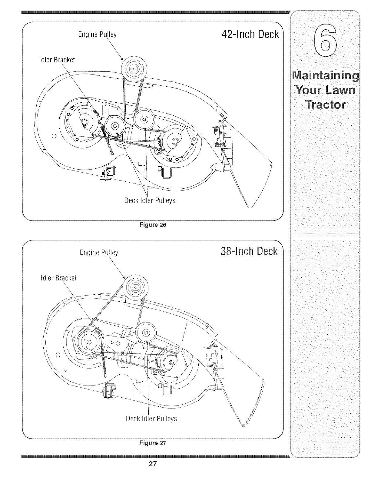
IdlerBracket
EnginePu_
DeckIdlerPulleys
42-Inch Deck
Figure 26
,J
Engine Pu,lley 38-Inch Deck
Idler Bracket
\
\
Deck Idler Pulleys
Figure 27
,J
27
; of this manualbeforestoringfor an extendedperiod, Manualfor properenginecare prior to storingyourtractor,
WARNING
Drain fuel only into an
approved container
outdoors, away from
an open flame. Al-
low engine to coon.
Extinguish cigarettes,
cigars, pipes, and
other sources of igni=
tion prior to draining
fuel.
Never store the ma-
chine or fuel container
indoors where there is
an open flame, spark
or pilot light such
as on water heater,
furnace, clothes dryer
or other gas appliance.
WARNING: Drain fueJ only into
an approved container outdoors,
away from an open flame. Allow
engine to coot. Extinguish
cigarettes, cigars, pipes, and
other sources of ignition prior to
draining fuel.
WARNING: Never store the
machine or fuel container indoors
where there is an open flame,
spark or pilot tight such as on
water heater, furnace, clothes
dryer or other gas appliance.
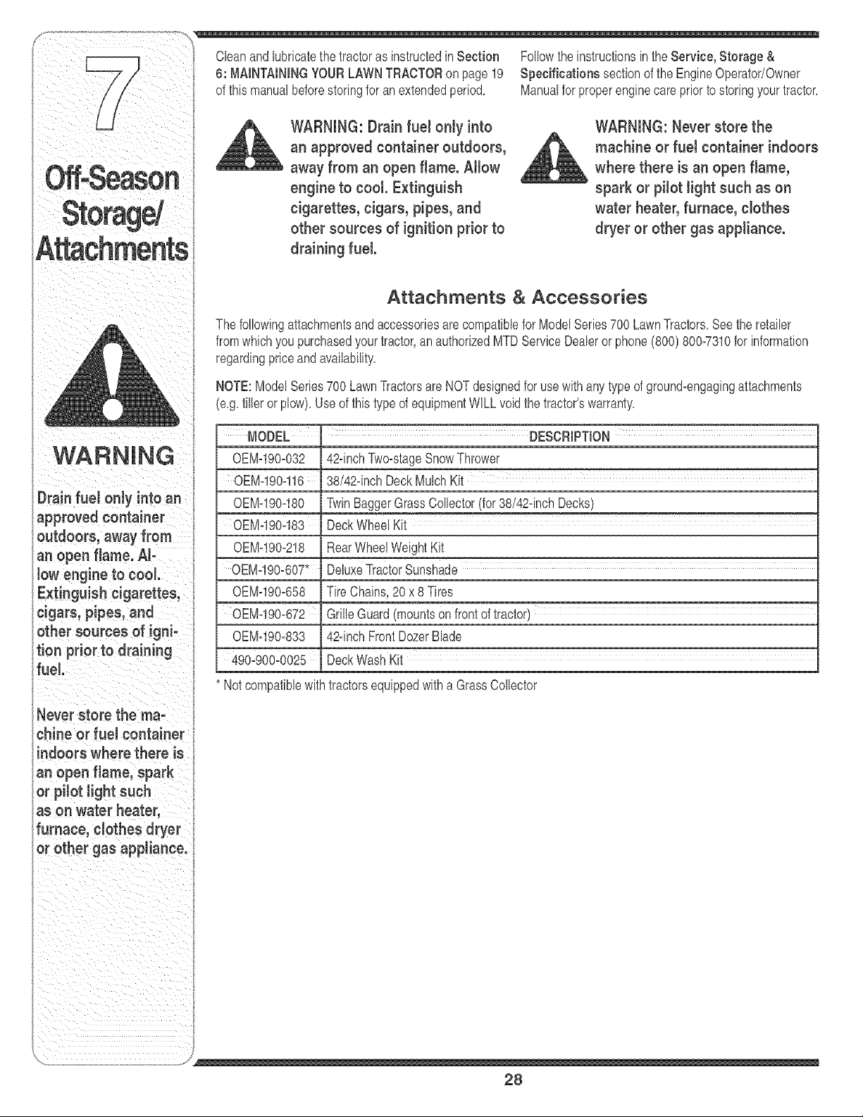
Attachments & Accessories
The followingattachmentsand accessoriesare compatiblefor ModelSeries700 LawnTractors,See the retailer
fromwhichyou purchasedyour tractor,an authorizedMTDServiceDealeror phone(800) 800-7310for information
regardingpriceand availability,
NOTE:ModelSeries700 LawnTractorsare NOTdesignedfor usewithany type of ground-engagingattachments
(e,g,tiller or plow),Use of thistype of equipmentWiLL voidthe tractor'swarranty,
MODEL m DESCfllPTION
0EM-190-032
0EM-190-116
OEMq90-180
0EN-190-183
0EM-190-218
0EM-190-607"
OEMq90-658
0EM-190-672
0EM-190-833
490-900-0025
42-inchTwo-stageSnowThrower
38/42-inchDeckMulch Kit
TwinBaggerGrassCollector(for38/42-inchDecks)
Deckwheel Kit
RearWheelWeightKit
DeluxeTractorSunshade
Tire Chains,20 x 8Tires
GrilleGuard(mountsonfrontoftractor)
42-inchFrontDozerBlade
DeckWash Kit
Notcompatiblewithtractorsequippedwitha GrassCollector
28
_andinstructions
29

For repairs beyond
the minor adjust-
ments listed here,
contact an authorized
service dealer.
Problem
Engine runs erratic
Cause
1, UnitrunningwithCHOKEapplied,
2, Sparkplugwire(s)loose,
3, Blockedfuel lineor stab fuel
4, Ventingas cap plugged,
5, Wateror dirt in fuel system,
6, Dirty aircbaner,
Remedy
1. PlacePTOknob (or lever)in
1, PushCHOKEcontrol(if so
equipped)in, or movethe throttle
controlout of the CHOKEposition,
2, Connectand tightenspark
plugwire(s),
3, Cban fuel line;fill tank withclean,
fresh(lessthan30 daysold)
gasoline,Replacefuel filter,if so
equipped,
4, Char vent or replaceif damaged,
5, Drainfuel tank, Refillwith
freshfuel
6, Replaceaircleanercartridge/eb=
mentor cleanpre=cleaner,if so
equipped,
3O

Problem Cause Remedy
. 2, Air flow restrbted,' 2, CLeangrassclippingsand debris
, , aroundthe engine:scoe!!ng
• • finsandbbwer housing.
Enginehesitates at 1, Sparkplug(s)gap tooclose, 1, Removespark plug(s)and reset
high RPM thegap,
' ..... equipped, ........ .....
Excessive
Vibration
Uneven cut
1, Cuttingblade looseor unbalanced,
2, Damagedor bentcutting blade,
1, Decknot balancedproperly,
2, Dullblade,
3, Uneventire pressure,
1, Tightenbladeand spindle,Balanc(
blade,
2, Replaceblade,
1, Performside-to-sidedeck adiust-
ment,
2, Sharpenor replaceblade,
3, Checktire pressurein all fourtires,
For repairs beyond
the minor adjust-
ments listed here,
contact an authorized
service dealer,
31

I
32

33

Use this page to make
notesandwritedown
importantinformation.
34

CAUFORNJA EMiSSiON CONTROL WARRANTY STATEMENT
YOUR WARRANTY RIGHTS AND OBLIGATIONS
The CaliforniaAir ResourcesBoardand MTDConsumerGroupInc are pleasedto explainthe evaporativeemissioncontrolsystemwarrantyon your2006 lawn
mower.In California,new lawnmowermust be designed,built andequippedto meet theState'sstringentanti-smogstandards.MTD ConsumerGroup Inc must
warrantthe EECSon your lawnmowerfor the periodof time listedbelow providedthere has beenno abuse,neglector impropermaintenanceof your lawnmower.
YourEECSmayincludeparts such as the carburetor,fuel-injectionsystem,the ignitionsystem,catalyticconverter,fuel tanks,fuel lines,fuel caps,valves,
canisters,filters,vapor hoses,clamps,connectors,and otherassociatedemission-relatedcomponents.
Where a warrantaMe condition exists, MTDConsumer Group _newill repair your Hawnmower at no cost to you ineHudingdiagnosis, parts and Habor.
MANUFACTURER'S WARRANTY COVERAGE:
Thisevaporativeemissioncontrol systemis warrantedfor twoyears. If anyevaporativeemission-relatedpart onyour equipmentis defective,the partwill be
repairedor replacedby MTDConsumerGroup Inc.
OWNER'S WARRANTY RESPONSIBILITIES:
Asthe lawn mowerowner,you are responsiblefor performanceof the requiredmaintenancelistedin yourowner'smanual. MTDConsumerGroup Inc recom-
mendsthat you retain all receiptscoveringmaintenanceon your lawnmower,but MTDConsumerGroup Inccannot denywarrantysolelyfor the lackof receipts.
Asthe lawn mowerowner,you shouldhoweverbe awarethat MTDConsumerGroup Inc maydenyyou warrantycoverageif yourlawn moweror a part has failed
dueto abuse,neglect, or impropermaintenanceor unapprovedmodifications.
Youare responsiblefor presentingyourlawn mowerto MTDConsumerGroup Inc'sdistributioncenter or servicecenteras soonas the problemexists.The
warrantyrepairsshouldbe completedin a reasonableamountof time, not to exceed30 days. If you havea questionregardingyour warrantycoverage,you should
contactthe MTDConsumerGroupIncService Departmentat 1-800-800-7310.
GENERAL EMISSIONS WARRANTY COVERAGE:
MTDConsumerGrouphc warrantsto the ultimatepurchaserandeachsubsequentpurchaserthat the lawnmoweris: Designed,built and equippedso as to
conformwithall applicable regulations;and freefrom defectsin materialsand workmanshipthatcausethe failure of a warrantedpart to be identicalin all material
respectsto that part as describedin MTDConsumerGroup Inc'sapplicationfor certification.
Thewarranty period beginson the datethe lawnmoweris deliveredto an ultimatepurchaserorfirst placedinto service.Thewarranty periodis twoyears.
Subjectto certain conditionsand exclusionsas statedbelow,the warrantyon emission-relatedparts is as follows:
1. Anywarrantedpart that is not scheduledfor replacementas requiredmaintenanceinthe writteninstructionssupplied, is warrantedfor the warranty period
statedabove. If the part fails duringthe periodof warrantycoverage,the partwill be repairedor replacedby MTDConsumerGroupInc accordingto subsection
(4) below.Anysuch part repairedor replacedunderwarrantywill be warrantedfor the remainderof the period.
2. Anywarrantedpart that is scheduledonly for regular inspectionin the writteninstructionssuppliedis warrantedfor thewarranty periodstated above.Any such
part repairedorreplacedunderwarrantywill be warrantedfor the remainingwarrantyperiod.
3. Any warrantedpart that is scheduledfor replacementas requiredmaintenanceinthe written instructionssuppliedis warrantedfor the periodof time beforethe
first scheduledreplacementdatefor that part. If the part failsbeforethe first scheduledreplacement,the partwill be repairedor replacedby MTDConsumer
GroupInc accordingto subsection(4) below.Anysuch part repairedor replacedunderwarrantywill be warrantedfor the remainderof the periodpriorto the
first scheduledreplacementpointfor the part.
4. Repairor replacementof any warrantedpart underthewarrantyprovisionshereinmustbe performedat a warrantystationat no chargeto theowner.
5. Notwithstandingthe provisionsherein,warrantyservicesor repairswill be providedat all of our distributioncentersthat arefranchisedto servicethe subject
enginesor equipment.
6. The lawnmowerowner will not be chargedfor diagnosticlaborthat is directlyassociatedwithdiagnosisof a defective,emission-relatedwarrantedpart,
providedthat such diagnosticwork is performedat a warrantystation.
7. MTDConsumerGroup Inc is liablefor damagesto other engineor equipmentcomponentsproximatelycaused bya failure underwarrantyof any warranted
part.
8. Throughoutthe lawnmowerwarrantyperiod stated above,MTDConsumerGroupIncwill maintaina supplyof warrantedparts sufficientto meetthe expected
demandfor such parts.
9. Any replacementpart may be usedinthe performanceof any warrantymaintenanceor repairsand mustbe providedwithoutchargeto the owner.Such use will
not reducethe warrantyobligationsof MTDConsumerGroupInc.
10.Add-onor modifiedpartsthat are notexemptedbythe Air ResourcesBoardmay not beused.The use of any non-exemptedadd-onor modifiedparts by the
ultimatepurchaserwill be groundsfor disallowinga warrantyclaims. MTDConsumerGroup Incwill notbe liableto warrantfailures of warrantedparts caused
bythe use of a non-exemptedadd-onor modifiedpart.
WARRANTED PARTS:
The repairor replacementof any warrantedpartotherwiseeligiblefor warrantycoveragemaybe excludedfrom such warrantycoverageif MTDConsumerGroup
Inc demonstratesthat thelawn mowerhas been abused,neglected,or improperlymaintained,andthat such abuse, neglect,or impropermaintenancewasthe
directcauseof the need for repairor replacementof the part.That notwithstanding,any adjustmentof a componentthat has a factory installed,and properly
operating,adjustmentlimiting device is still eligiblefor warrantycoverage.The followingemissionwarrantyparts list are covered:FuelLine,Fuel LineClamps
m

MANUFACTURER'S LiMiTED WARRANTY FOR
Thefimitedwarrantyset forth belowis givenby MTDLLCwithrespect
to new merchandisepurchasedandusedin the UnitedStates,its
possessionsandterritories.
"MTD"warrantsthis productagainstdefectsin materialand workman=
shipfor a periodof two (2) yearscommencingon thedate of original
purchaseandwill,at itsoption,repairor replace,free of charge,any
partfound to bedefectiveinmaterialsorworkmanship.This limitedwar=
rantyshallonlyapply if this producthas beenoperatedand maintained
inaccordancewith theOperator'sManualfurnishedwith the product,
andhas notbeensubiectto misuse,abuse,commercialuse, neglect,
accident,impropermaintenance,alteration,vandalism,theft,fire,water,
ordamagebecauseof otherperil or naturaldisaster.Damageresulting
fromthe installationor useof any part,accessoryor attachmentnot
approvedby MTDfor use with the product(s)coveredbythis manual
will voidyourwarrantyas to any resultingdamage.
Normalwearpartsare warrantedto be free fromdefects in materialand
workmanshipfor a period of thirty (30) days fromthe date of purchase.
Normalwearparts include,butare notlimitedto itemssuch as: batter=
ies,belts,blades,bladeadapters,grassbags,riderdeck wheels,seats,
snowthrowerskidshoes,shaveplates,auger spiralrubberandtires.
NOW TO OBTAmNSERVICE: Warranty service is available, WITH
PROOFOF PURCHASE,through your !ocal authorized service
dealer. To locate the dealer in your area, check your Yellow Pages,
or contact MTD LLC at RO. Box 361131,Cleveland, Ohio 44136-
0019, or call 1-800-800-7310 or 1-330-220-4683 or log on to our
Web site at www.mtdproducts.com.
Thislimitedwarrantydoesnot providecoveragein the followingcases:
a. Theengineor componentpartsthereof.These itemsmaycarrya
separatemanufacturer'swarranty.Referto applicablemanufacturer's
warrantyfor termsand conditions.
b. Log splitterpumps,valves,andcylindershavea separateone year
warranty.
c. Routinemaintenanceitemssuchas lubricants,filters,blade
sharpening,tune=ups,brakeadiustments,clutchadjustments,deck
adiustments,andnormaldeteriorationof the exteriorfinishdueto
useor exposure.
d. Servicecompletedbysomeoneotherthanan authorizedservice
dealer.
e. MTDdoesnot extendanywarrantyfor productssold or exported
outsideof the UnitedStates,itspossessionsandterritories,except
thosesold throughMTD'sauthorizedchannelsof exportdistribution.
f. Replacementpartsthat are not genuineMTDparts.
g. Transportationchargesandservicecalls.
No impliedwarranty, includingany impliedwarranty of mero
chantability of fitness for a particular purpose, applies after the
applicable period of express written warranty above as to the
parts as identified. No other express warranty, whether written or
oral, except as mentioned above, given by any person or entity,
including a dealer or retailer, with respect to any product, shall
bind MTD.During the period of the warranty, the exclusive remedy
is repair or replacement of the product as set forth above.
The provisions as set forth in this warranty provide the sole and
exclusive remedy arising from the sale. MTDshall not be liable
for incidental or consequential loss or damage including, without
limitation, expenses incurred for substitute or replacement lawn
care services or for rental expenses to temporarily replace a
warranted product.
Somestatesdo notallowthe exclusionorlimitationof incidentalor
consequentialdamages,or limitationsonhow longan impliedwarranty
lasts,so the aboveexclusionsor limitationsmaynotapply to you.
In no event shallrecoveryof any kindbegreaterthanthe amountof the
purchasepriceof the productsold. Alteration of safety features of
the product shall void this warranty. Youassumethe risk and liability
for loss,damage,or injuryto you andyourpropertyand/orto othersand
theirpropertyarisingout of the misuseor inabilityto usethe product.
This limitedwarrantyshallnot extendto anyoneotherthan the original
purchaserorto the personfor whomit was purchasedas a gift.
HOWSTATELAW RELATESTO THISWARRANTY:This limited
warrantygivesyou specificlegal rights,and youmayalso haveother
rightswhichvaryfromstateto state,
IMPORTANT:OwnermustpresentOriginalProofof Purchaseto obtain
warrantycoverage,
MTD LLC, P.O. BOX 361131 CLEVELAND, OHiO 44136-0019; Phone: 1-800-800-7310, 1-330-220-4683