INSTALLATION,
OPERATION &
MAINTENANCE
MANUAL
Pizza Prep Tables
Sandwich/Salad Units
Under-counter Refrigerators
and Freezers
Worktop Refrigerators and
Freezers
IMPORTANT
Please read this manual completely
before attempting to install or operate this equipment.
Service and Installation Manual
2
COMMECIAL REFRIGERATOR SAFETY
Your safety and the safety of others are very important.
We have provided many important safety messages in this manual and on your appliance. Always read and
obey all safety messages.
Our product instructions will be uploaded on our company official website.
This is the Safety Alert Symbol. This symbol alerts you to potential hazards that can
kill or injure you and others. All safety messages will follow the Safety Alert Symbol
and either the words” DANGER”, “WARNING” or “CAUTION”.
Danger means that failure to heed this safety
statement may result in severe personal injury or
death.
Warning means that failure to heed this safety
statement may result in extensive product
damage, serious personal injury, or death.
Caution means that failure to heed this safety
statement may result in minor or moderate
personal injury, or property or equipment damage.
All safety messages will alert you to what the potential hazard is, tell you how to reduce the chance of injury,
and let you know what can happen if the instructions are not followed.
If the supply cord is damaged, it must be replaced by the manufacturer, its service agent or similarly
qualified persons in order to avoid a hazard.
This appliance is not intended for use by persons (including children) with reduced physical, sensory or
mental capabilities, or lack of experience and knowledge, unless they have been given supervision or
instruction concerning use of the appliance by a person responsible for their safety.
Children should be supervised to ensure that they do not play with the appliance.
This appliance can be used by children aged from 8 years and above and persons with reduced physical
sensory or mental capabilities or lack of experience and knowledge if they have been given supervision or
instruction concerning use of the appliance in a safe way and understand the hazards involved. Children
shall not play with the appliance. Cleaning and user maintenance shall not be made by children without
supervision.
Keep the appliance and its cord out of reach of children less than 8 years.
Do not store explosive substances such as aerosol cans with a flammable propellant in this appliance.
The appliance use flammable insulation blowing gas C5H10, disposal of the appliance shall in accordance
with the regulations of local authorities.

Service and Installation Manual
3
Th
e key for appliance electric box should be safe kept by qualified persons in order to avoid a hazard
WARNING: Keep ventilation openings, in the appliance enclosure or in the built-in structure, clear of
obstruction.
WARNING: Do not use mechanical devices or other means to accelerate the defrosting process, other than
those recommended by the manufacturer.
WARNING: Do not damage the refrigerant circuit.
WARNING: Do not use electrical appliances inside the food storage compartments of the appliance, unless
they are of the type recommended by the manufacturer.
Handling, moving, and use of the refrigerator or freezer to avoid either damaging the refrigerant tubing, or
increasing the risk of a leak
L’opération, le mouvement et l’utilisation du réfrigérant ou le congélateur doivent éviter les dommages du
tuyau réfrigérant ou le rique de la fuite.
Caution – Risk of Fire or Explosion due to Flammable Refrigerant Used. Follow Handling
Instructions Carefully in Compliance with U.S. Government Regulations.
Component parts shall be replaced with like components and that servicing shall be done by factory
authorized service personnel, so as to minimize the risk of possible ignition due to incorrect parts or
improper service.
Les pièces de rechange doivent être remplacées par les components relatifs et les opérations doivent être
faites par les professionnels afin de minimaliser le risque d’allumage à cause des parts incorrects ou des
opérations impropres.
CAUTION – Risk Of Fire Or Explosion Due To Puncture Of Refrigerant Tubing; Follow Handling Instructions
Carefully. Flammable Refrigerant Used
DANGER: Risk of child entrapment. Before you throw away your old refrigerator or freezer:
Take off the doors
Leave the shelves in place so that children may not easily climb inside

4
Installation, Operation & Maintenance Manual
TABLE OF CONTENTS
SPECIFICATIONS .............................................................................................................................................................................5
REGISTRATION ................................................................................................................................................................................6
SAFETY INSTRUCTIONS .................................................................................................................................................................7
INTRODUCTION ...............................................................................................................................................................................8
Site Preparation..........................................................................................................................................................................8
RECEIVING AND INSPECTING ......................................................................................................................................................8
Serial Number Location ..............................................................................................................................................................8
INSTALLATION .................................................................................................................................................................................9
Location .....................................................................................................................................................................................
9
Inside cabinet .....................................................................................................................................................................9
Outside cabinet ...................................................................................................................................................................9
Electrical connection ..................................................................................................................................................................9
Leveling .....................................................................................................................................................................................9
Stabilizing ............................................................................................................................................................................9
OPERATION ...................................................................................................................................................................................10
Refrigerated Cabinets ..............................................................................................................................................................10
Defrosting .................................................................................................................................................................................10
Front Panel Controls and Indicators .........................................................................................................................................10
Functions ..................................................................................................................................................................................11
Display the set point: .........................................................................................................................................................11
Change the set point: ........................................................................................................................................................11
Manual Defrost ..................................................................................................................................................................11
Keyboard Lock ..................................................................................................................................................................11
Keyboard Unlock ...............................................................................................................................................................11
Alarm Codes.............................................................................................................................................................................11
Display and Reset Alarm ..........................................................................................................................................................11
MAINTENANCE ..............................................................................................................................................................................1 2
Refrigerators and Freezers ......................................................................................................................................................12
Cleaning the Condenser Coil ...................................................................................................................................................1 2
Stainless Steel Care and Cleaning .............................................
.............................................................................................12
Gasket Maintenance ................................................................................................................................................................ 13
Doors/Hinges............................................................................................................................................................................1 3
Drain Maintenance ...................................................................................................................................................................13
Door Replacement and Adjustment..........................................................................................................................................13
Open the Bottom Shroud..........................................................................................................................................................1 3
WIRING DIAGRAMS .......................................................................................................................................................................1 4
Models:
Models:
Models:
APP48RZ,APP71RZ,....................................
APP94RZ,AST28RZ,AMT28RZ
...............................................................................................................
AUC27RZ .................................................................................................................................................................. .25
Models: AUC48RZ , AUC60RZ ............................................................................................................................................... 26
Models: AUC27FZ ................................................................................................................................................................... 27
Models: AUC48FZ , AUC60FZ ................................................................................................................................................ 28
..................................................................................................................................
14
Models: AUC27RZ, AUC48RZ,AUC60RZ
...............................................................................................................................
17
Models: AUC27FZ , AUC48FZ,AUC60FZ
.............................................................................................................................
15
Models:
Models:
APP48RZ
APP71RZ
................................................................................ ................................................................................
................................................................................ ..................................................................................
19
20
Models:
Models:
AST28RZ,AMT28RZ
AST48RZ,AST60RZ,AMT48RZ,AMT60RZ
................................................................................ ..............................................................
.................................... ...........................................................................
22
23
18
ARCTIC AIR WARRANTY ................................................................................................................................................................29
Models:
AST48RZ,AST60RZ,AMT48RZ,AMT60RZAST72RZ,AMT72RZ
................................................................................
16
Models: AST72RZ,AMT72RZ ................................................................................ ............................................................... 24
Models:
APP94RZ
................................................................................ ..................................................................................
21
5
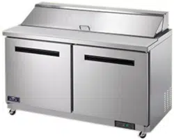
UNDER-COUNTER REFRIGERATORS AND FREEZERS
SPECIFICATIONS
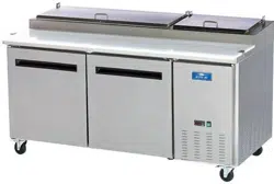
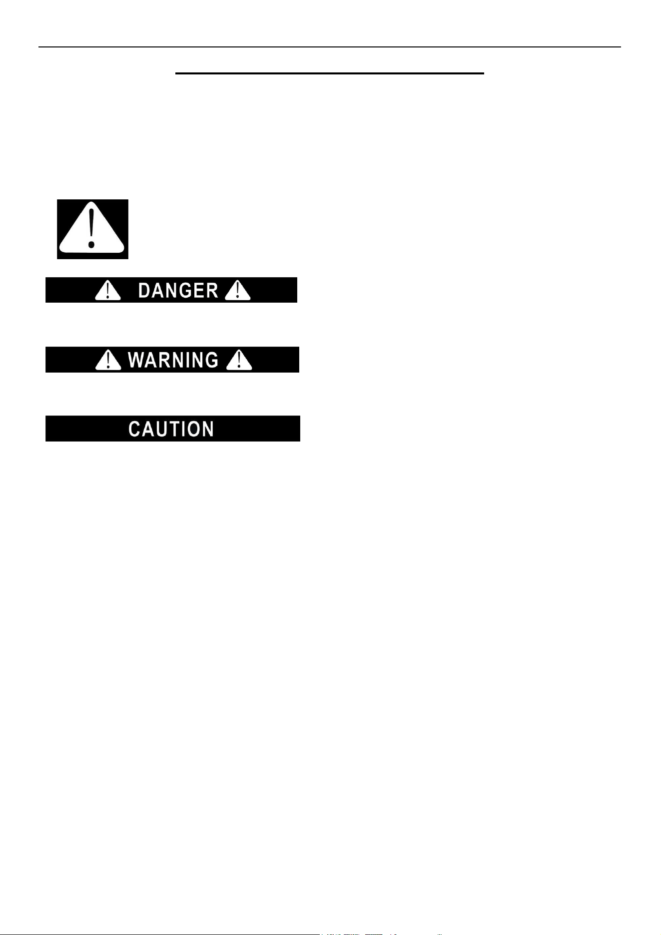
PIZZA PREP TABLES
MODEL # V/Hz/Ph AMPS STORAGE
CAPACITY
Cu-ft
PAN
1/3
Size
SHELF
CAPACITY
Sq-ft
HP BTU CHARGE
Oz
SHIP
WEIGHT
Lbs
NEMA
PLUG
APP48RZ 115/60/1 5 12 6 16 1/2 1365 3.70 348 5-15P
APP71RZ 115/60/1 5 22 9 34 1/2 1365 3.70 432 5-15P
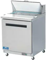
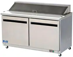
SANDWICH/SALAD UNITS
MODEL # V/Hz/Ph AMPS STORAGE
CAPACITY
Cu-ft
PAN
1/6
Size
SHELF
CAPACITY
Sq-ft
HP BTU CHARGE
Oz
SHIP
WEIGHT
Lbs
NEMA
PLUG
AST28RZ 115/60/1 3 7 8 14 3/8 853 3 276 5-15P
AST48RZ 115/60/1 4.3 12 12 26 1/2 1365 3.17 313 5-15P
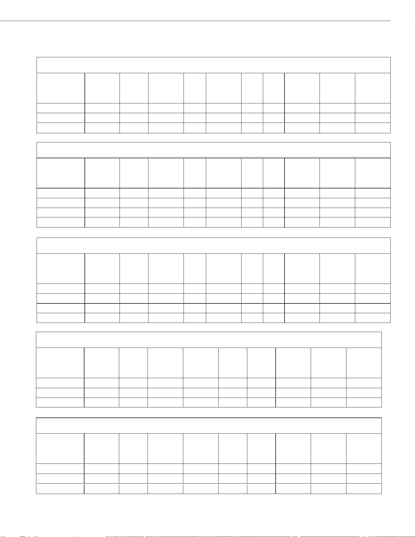
UNDERCOUNTER & WORKTOP REFRIGERATORS
MODEL # V/Hz/Ph AMPS STORAGE
CAPACITY
Cu-ft
SHELF
CAPACITY
Sq-ft
HP BTU CHARGE
Oz
SHIP
WEIGHT
Lbs
NEMA
PLUG
AUC27RZ 115/60/1 1.5 6.5 14 3/8 2800 2.47 243 5-15P
AUC48RZ 115/60/1 3 12 26 3/8 3000 2.65 300 5-15P
UNDERCOUNTER FREEZERS
MODEL # V/Hz/Ph AMPS STORAGE
CAPACITY
Cu-ft
SHELF
CAPACITY
Sq-ft
HP BTU CHARGE
Oz
SHIP
WEIGHT
Lbs
NEMA
PLUG
AUC27FZ 115/60/1 1.9 6.5 14 1/2 3500 3.35 291 5-15P
AUC48FZ 115/60/1 4 12 26 1/2 3800 3.53 340 5-15P
AST60RZ 115/60/1 4.3 15.5 16 30 1/2 1365 3.17 362 5-15P
AST72RZ 115/60/1 4.3 18 18 36 1/2 1365 3.35 408 5-15P
MEGATOP SANDWICH/SALAD UNITS
MODEL # V/Hz/Ph AMPS STORAGE
CAPACITY
Cu-ft
PAN
1/6
Size
SHELF
CAPACITY
Sq-ft
HP BTU CHARGE
Oz
SHIP
WEIGHT
Lbs
NEMA
PLUG
AMT28RZ 115/60/1 3 7 12 14 3/8 3 276 5-15P
AMT48RZ 115/60/1 4.3 12 18 26 1/2 3.17 313 5-15P
AMT60RZ 115/60/1 4.3 15.5 24 30 1/2 3.17 362 5-15P
AMT72RZ 115/60/1 4.3 18 27 36 1/2 3.35 408 5-15P
APP94RZ 115/60/1 5 32 12 54 3/4 1877 3.70 582 5-15P
853
1365
1365
1365
AUC60RZ 115/60/1 3 15.5 30 3/8 3000 2.82 380 5-15P
AUC60FZ 115/60/1 5 15.5 30 5/8 3800 3.53 388 5-15P

6
Installation, Operation & Maintenance Manual
UNDER-COUNTER REFRIGERATORS AND FREEZERS
REGISTRATION
The.installation.date.and.appliance.model.must.be.documented.by.the.end.purchaser...
Also,.refer.to.the.Warranty.section.for.additional.details.on.registering.the.appliance.
Dealer.Information:
Installer.Information:
Installation.Date:
Installation, Operation & Maintenance Manual
7
UNDER-COUNTER REFRIGERATORS AND FREEZERS
SAFETY INSTRUCTIONS
General Safety
WARNING
Arctic Air accepts no responsibility for any situation resulting from work carried out in an
unprofessional manner, or from the incorrect interpretation or application of regulations.
General Installation
WARNING
Incorrectinstallationoranymodicationsmadetotheappliancemaydamagepropertyor
result in injury or death.
Electrical
WARNING
Electrical connections or any work required on the electrical circuits inside the appliance
mustbeperformedbycertiedtechniciansincompliancewithlocal,state,andfederal
regulations.
WARNING
Make sure all facility electrical connections are in compliance with all local and federal
electrical code regulations.
Inspection and Maintenance
WARNING
Appliance maintenance must be carried out by only by suitably trained personnel.
WARNING
Before any maintenance work is performed, the appliance must be disconnected from the
electrical supply. Apply a lockout tag to the electrical supply connection.
WARNING
All replacement parts that are not supplied by Arctic Air must be pre-approved before
installation.
Repair Work Safety
WARNING
Repair work must only be performed by Arctic Air or one of its authorized representatives.
Arctic Air accepts no responsibility for any situation resulting from work performed by
untrained and/or unauthorized technicians.

8
Installation, Operation & Maintenance Manual
UNDER-COUNTER REFRIGERATORS AND FREEZERS
INTRODUCTION
This.manual.covers.the.Under-counter.Refrigerators.and.
Freezers..Please.read.this.manual.completely.before.at-
tempting.to.install.or.operate.this.equipment.
Site Preparation
The.installation.site.must.be.cleaned.and.prepared.prior.
to.the.equipment.delivery...
• Refer.to.the.SPECIFICATIONS.and.have.a.licensed.
electrician conrm that all electrical requirements
are satised.
• Conrm that all ooring is structurally strong enough
to.support.the.weight. of.a.fully. loaded.unit;.a.fully.
loaded. unit. can. weigh. as. much. as. 1500. pounds...
Consult with a structural engineer for conrmation if
there is any reason to doubt the oor strength.
• Conrm that adequate ventilation has been provid-
ed,.and.that.the.unit.will.not.be.located.close.to.a.
heat.source.
• For all units on casters, conrm that the oor is level
where.the.unit.is.to.be.located.
RECEIVING AND INSPECTING
Exercise.care.to.prevent.damaging.the.equipment.dur-
ing.unloading.and.on-site.transporting.
1.. Visually. inspect. the. exterior. of. the. package,. skid.
and/or.container..Report.any.damage.to.the.carrier.
immediately.
2.. If.any.packaging.damage.is.noted,.open.and.inspect.
the.contents.with.the.carrier.
3.. If.concealed.damage.is.discovered.after.unpacking.
the equipment notify the carrier. Notication must
be.made.both.in.writing.and.verbally.
4.. Check. the. compressor. compartment. housing. and.
visually inspect the refrigeration package. Conrm
that.the.lines.are.secure.and.the.base.is.intact.
5.. Request.the.required.damage.forms.and.an.equip-
ment.damage.inspection.by.the.shipping.company..
The.inspection.should.be.performed.within.10.days.
from.receipt.of.the.equipment.
6.. Retain. all. crating. material. until. an. inspection. has.
been.performed.or.waived.
Serial Number Location
The.serial.number.of.all.self-contained.refrigerators.and.
freezers.is.located.inside.the.unit.on.the.left.hand.side.
near.the.top.on.the.wall..Have.the.serial.number.avail-
able.when.calling.for.parts.or.service.
This.manual. covers.only.standard. units..For. a.custom.
unit,.consult.the.customer.service.department..See.the.
customer.service.phone.number.listed.on.the.last.page.
Installation, Operation & Maintenance Manual
9
UNDER-COUNTER REFRIGERATORS AND FREEZERS
INSTALLATION
Location
All.units.are.intended.for.indoor.use.only..A.fully.loaded.
unit.can.weigh.as.much.as.1500.pounds...Choose.a.loca-
tion with a level oor strong enough to support the total
weight of a fully loaded unit. Reinforce the oor if neces-
sary..
For the most efcient refrigeration, provide good air cir-
culation.around.the.unit..
Inside cabinet
Do.not.pack.the.unit.interiors.so.that.air.circulation.is.im-
peded..The.refrigerated.air.is.discharged.at.the.top.rear.
of the unit. Allow for proper air ow from the top rear to
the bottom of the unit. Obstructions to this air ow can
cause.evaporator.coil.freeze.ups.and.loss.of.temperature.
or overow of water from the evaporator drain pan. The
shelves.have.a.rear.turn.up.on.them.to.prevent.obstruc-
tions to the rear air ow. However, bags and other items
located. at. the. rear. of. the. cabinet. may. obstruct. the. air.
ow.
Outside cabinet
Be sure that the unit has access to ample air ow. Avoid
hot.corners.and.locations.near.stoves.and.ovens..Do.not.
install.the.unit.closer.than.two.inches.from.a.wall..To.pre-
vent.air.obstruction,.do.not.locate.large.boxes.and/or.tall.
stacks.of.product.that.might.obstruct.the.air.exhaust.or.
the.air.inlet.
CAUTION
If the unit is laid on its side or back for any reason,
allow a minimum of 24 hours in the upright position,
beforestart-uptoallowcompressoroiltoowback
to the sump. Failure to meet this requirement can
cause compressor failure, unit damage, and will
void the unit warranties.
Electrical connection
Refer. to. the. amperage. data. provided. in. the. SPECIFI-
CATIONS,.the.serial.tag,.the.local.electrical.code.and/or.
the.National.Electrical.Code..Have.a.licensed.electrician.
conrm that the facility wiring is adequate for the unit and
that.a.protected.circuit.of.the.correct.voltage.and.amper-
age is provided for each unit. Conrm that the unit is
connected.only.to.the.proper.protected.power.source..
DANGER
TURN THE ON/OFF SWITCH TO OFF AND
DISCONNECT THE UNIT FROM THE POWER
SOURCE WHENEVER PERFORMING SERVICE,
MAINTENANCE FUNCTIONS OR CLEANING
THE UNIT.
Leveling
Level.the.cabinet.to.improve.performance,.to.better.align.
the. doors,. to. reduce. uneven. strain. on. the. cabinet. and.
reduce.movement.of.the.contents.on.the.shelves..Use.a.
level.to.level.the.unit.from.front.to.back.and.side.to.side..
Units. supplied. with. legs. have. adjustable. bullet. feet. to.
make.the.leveling.adjustments..If.the.unit.is.supplied.with.
casters,. no. leveling. adjustments. are. available.. Ensure.
the oor is level, where the casters unit is located.
Stabilizing
Casters.are.provided.for.convenience,.ease.of.cleaning.
underneath.and.for.mobility..Install.the.unit.on.a.level.sur-
face,.in.a. stable. condition.and.lock. the. front.wheels. to.
prevent.movement.
10
Installation, Operation & Maintenance Manual
UNDER-COUNTER REFRIGERATORS AND FREEZERS
OPERATION
Refrigerated Cabinets
The.internal.temperature. range. for.all. food. prep.units,.
under-counter.and.worktop.refrigerators.is.34°F.to.38°F..
The. internal. temperature. range. for. under-counter. and.
worktop. freezers. is. -3°F. to. -7°F.. The. rail. temperature.
range. for. all. prep. units. is. 33°F. to. 41°F.. Operate. the.
food.prep.units. only. with.the. pans. in.place.. Operating.
food.prep.units.without.pans.and/or.pan.covers.in.place.
lowers the efciency and may damage the unit due to
continuous.running..Opening.and.closing.the.door.must.
be.minimized.to.allow.the.unit.to.maintain.optimum.re-
frigeration.temperature..Top.section.is.not.intended.for.
overnight.storage..Product.must.be.removed.from.pans..
Empty.pans.can.remain.in.cabinet.
Defrosting
Every.6.hours,.the.unit.turns.off.and.the.controller.dis-
plays. the. defrost. symbol.. This. allows. the. evaporator.
coil.to.clear.the.ice..When.the.coil.temperature.reaches.
the.terminal.temperature.(or.after.20.minutes).the.unit.
re-starts.
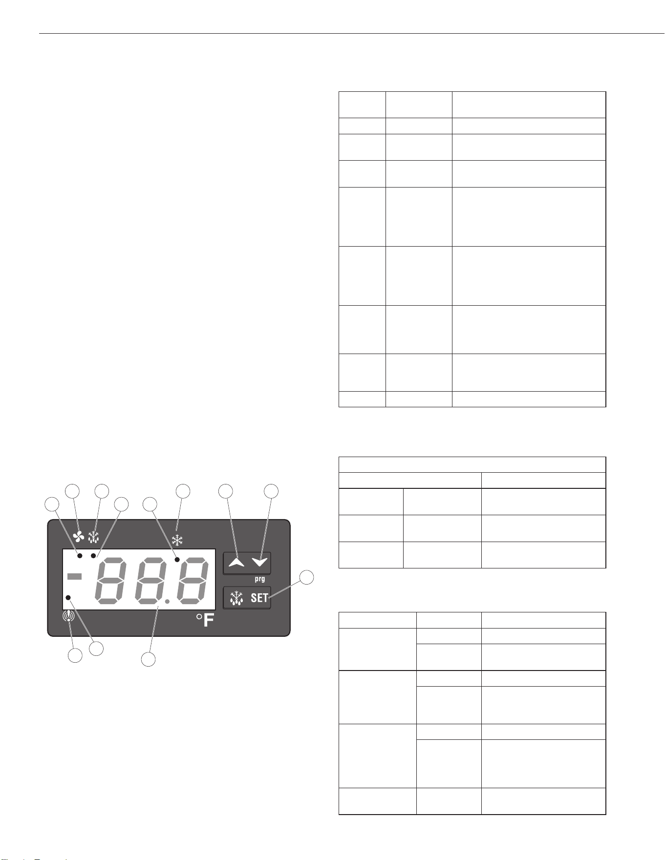
Front Panel Controls and Indicators
The.front.panel.controls.and.indicators.are.used.to.set.
and.display.the.unit.functions.and.status.
Callout
No.
Control /
Indicator
Function
1 Fan
Indicates.the.fans.are.running.
2 Defrost
Press.to.start.the.manual.defrost.
cycle.
3 Compressor
Indicates.the.compressor.is.
running.
4
Up.Arrow
To.display.the.last.temperature.
alarm..
In.programming.mode.it.
browses.the.parameter.codes.or.
increases.the.displayed.value.
5 Down.Arrow
To.display.the.last.temperature.
alarm..
In.programming.mode.it.
browses.the.parameter.codes.or.
decreases.the.displayed.value.
6 SET
Used.to.display.a.target.set.
point;.in.programming.mode.it.
elects a parameter or conrm an
operation.
7 Display
Indicates.the.room.temperature,.
the.set.points.and.the.alarm.
codes.
8 Alarm
Indicates.a.temperature.alarm.
Key. combinations. are. used. to. perform. functions. that.
cannot.be.performed.with.a.single.key.
Key Combinations
Press Keys Result
Up.Arrow Down.Arrow
Locks.and.unlocks.the.
keyboard.
SET
Down.Arrow
Enters.the.programming.
mode.
SET
Up.Arrow
Returns.to.the.room.
temperature.display.
The.LED.functions.display.operational.conditions.
Callout No. Mode LED Function
1a
On
Fans.enabled
Flashing
Fans.delay.after.defrost.
in.progress
2a
On Defrost.enabled
Flashing
-Programming.phase.
(ashing with “icon”)
-.Drip.time.in.progress
3a
On
Compressor.enabled
Flashing
-Programming.phase.
(ashing with “icon”)
-Anti-short.cycle.delay.
enabled
8a On
A.temperature.alarm.
happened
1
1a
8a
3a2a
2
8
7
4 5
6
3
Installation, Operation & Maintenance Manual
11
UNDER-COUNTER REFRIGERATORS AND FREEZERS
Functions
Display the set point:
1.. Press. and. release. the. SET. button,. the. set. point.
value.is.displayed.
2.. Press. and. release. the. SET. button. (again). or. wait.
ve seconds to return to the probe value display.
Change the set point:
1.. To.change.the.set.point.value,.press.the.SET.button.
and.hold.for.a.minimum.of.two.seconds.
The. set. point. value. is. displayed. and. the. Compressor.
LED.starts.blinking.
2.. For. the. next. ten. seconds,. the. set. value. can. be.
changed.using.the.Up.Arrow.or.the.Down.Arrow.but-
tons.
3.. To.save.the.new.set.point.value.press.the.SET.key.
again.(or.wait.ten.seconds).
Manual Defrost
Press.the.Defrost.button.and.hold.for.a.minimum.of.two.
seconds..The.manual.defrost.cycle.starts.
Keyboard Lock
1.. Press. the. Up.Arrow. and. Down.Arrow. buttons. and.
hold.for.a.minimum.of.three.seconds.
2.. The. “POF” message is displayed when the key-
board.is.locked..With.the.keyboard.locked.only.the.
set.point.or.the.max/min.temperature.is.displayed.
3.. If.any.key. is.pressed. for.more.than. three.seconds.
the “POF” message is displayed.
Keyboard Unlock
Press.the.Up.Arrow. and.Down.Arrow. buttons.and.hold.
for a minimum of three seconds. The “Pon” message is
displayed.when.the.keyboard.is.unlocked.
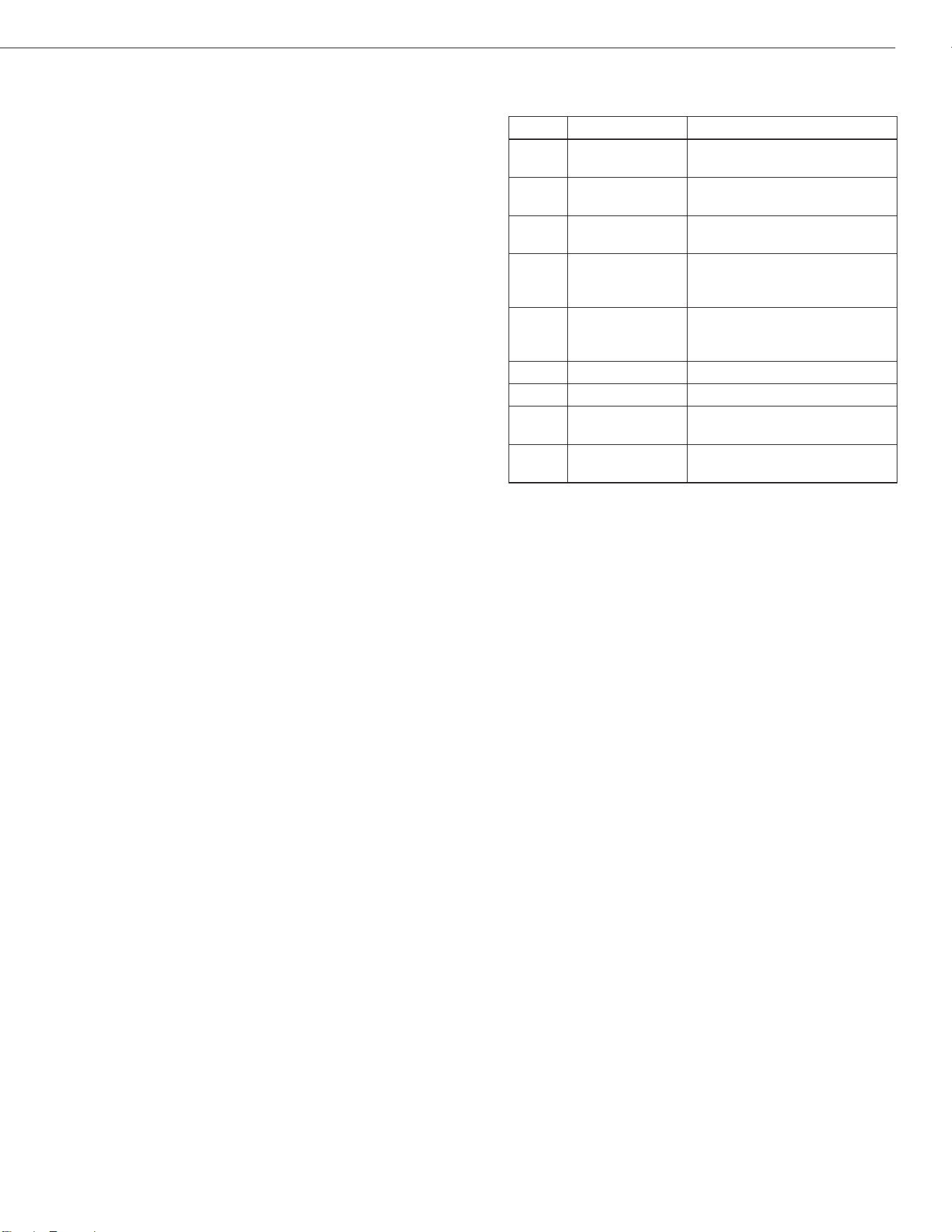
Alarm Codes
CODE CAUSE OUTPUTS
P1
Room.probe.
failure
Compressor.output.according.
to.par.Con.and.COF
P2
Evaporator.
probe.failure
Defrost.end.is.timed
P3
Condenser.
probe.failure
Outputs.unchanged.
HA
Maximum.
temperature.
alarm
Outputs.unchanged
LA
Minimum.
temperature.
alarm
Outputs.unchanged
dA Door.open Compressor.and.fans.restart
EA External.alarm Outputs.unchanged
CA
Serious.external.
alarm.(i1F=bal)
All.outputs.off
CSd
Condenser.
alarm
All.outputs.off
Display and reset alarm
1.. Press. the. Up.Arrow. and. Down.Arrow. buttons. to.
display.the.alarm.code.
2.. Press.and. hold.the. SET.button.until.the.reset.(rst).
message.is.displayed.then.release...
. Press.the.SET.button.again,.the.reset.(rst).message.
blinks.and.the.room.temperature.is.displayed.
12
Installation, Operation & Maintenance Manual
UNDER-COUNTER REFRIGERATORS AND FREEZERS
MAINTENANCE
DANGER
TURN OFF THE POWER SWITCH AND
DISCONNECT THE UNIT FROM THE POWER
SOURCE WHENEVER PERFORMING SERVICE/
MAINTENANCE FUNCTIONS AND/OR
CLEANING THE REFRIGERATED AREA.
Refrigerators and Freezers
Clean.the.interior.and.exterior.using.soap.and.warm.wa-
ter. If this is not sufcient, use ammonia and water or a
nonabrasive.liquid.cleaner..When.cleaning.the.exterior,.
always.rub.with.the.stainless.steel.grain.to.avoid.marring.
the nish.
Do.not.use.an.abrasive.cleaner,.it.may.scratch.the.stain-
less.steel.and/or.the.plastic..Abrasive.cleaners.can.also.
damage.the.breaker.strips.and.gaskets.
Cleaning the Condenser Coil
Clean.the.condenser.coil.a.minimum.of.every.90.days..
If.there.is.a.large.amount.of.debris,.dust.or.grease.ac-
cumulation.prior.to.the.90.day.cycle,.reduce.the.cleaning.
cycle.to.every.30.days.
If.the.buildup.on.the.coil.consists.of.only.light.dust.and.
debris,. clean. the. condenser. coil. using. a. brush.. For.
heavier.dust.buildup,.use.a.vacuum.or.compressed.air.
If.heavy.grease.is.present.use.a.refrigeration.degreas-
ing agent designed specically for the condenser coils.
Spray. the. condenser. coil. with. degreasing. agent. and.
blow.through.with.compressed.air.
Failure. to.maintain.a.clean. condenser. coil. can. initially.
cause.high.temperatures.and.excessive.run.times..Con-
tinuous.operation.with.dirty.or.clogged.condenser.coils.
may.result. in.compressor.failures..Neglecting.the. con-
denser.coil.cleaning.procedures.will.void.any.warranties.
associated.with.the.compressor.
CAUTION
Never use a high pressure water wash for this
cleaning procedure as water can damage the
electrical components located near or on the
condenser coil.
Stainless Steel Care and Cleaning
Stainless.steel.contains. 70-80%. iron.which.will. rust..It.
also.contains. 12-30%.chromium.which. forms.an. invis-
ible passive lm over the steel’s.surface.that.acts.as.a.
corrosion.shield..As.long.as.the.protective.layer.remains.
intact, the metal remains stainless. If the lm is broken
or.contaminated,.outside.elements.can.break.down.the.
steel.and.begin.to.form.rust.or.discoloration.
To.properly.clean.stainless.steel,.use.soft.cloths.or.plas-
tic.scouring.pads.
CAUTION
Never use steel pads, wire brushes or scrapers to
clean stainless steel surfaces.
Cleaning.solutions.must.be.alkaline.based.or.non-chlo-
ride.cleaners..Any.cleaner.containing.chlorides.will.dam-
age the stainless steel protective lm. Chlorides are also
commonly.found.in.hard.water,.salts,.and.household.and.
industrial.cleaners..If.cleaners.containing.chlorides.are.
used,. be. sure. to. rinse. repeatedly. and. dry. thoroughly.
upon.completion.
Perform.routine.stainless.steel.cleaning. with.soap.and.
water..Extreme.stains.or.grease.should.be.cleaned.with.
a.non-abrasive.cleaner.and.plastic.scrub.pad.(rub.with.
the.grain)..There.are.also.stainless.steel.cleaners.avail-
able.which.can.restore.the.protective.layer.and.preserve.
the nish.
Early.signs.of.stainless.steel.breakdown.may.consist.of.
small.pits.and.cracks..If.these.early.signs.are.present,.
clean thoroughly and apply a cleaner specically de-
signed.for.stainless.steel.cleaners.to.attempt.to.restore.
the.passivity.
CAUTION
Never use an acid based cleaning solution. In
addition, many food products have an acidic
contentwhichcandeterioratethenish.Besure
to clean the stainless steel surfaces of all food
products. Common acidic based food items
include; tomatoes, peppers and other vegetables.
Installation, Operation & Maintenance Manual
13
UNDER-COUNTER REFRIGERATORS AND FREEZERS
Gasket Maintenance
Gaskets. require. regular. cleaning. to. prevent. mold. and.
mildew. buildup. and. to. maintain. the. gasket. elasticity...
Clean.gaskets.with.warm.soapy.water..Avoid.full.strength.
cleaning.products.on.gaskets,.this.can.cause.the.gaskets.
to.become.brittle.and.prevent.proper.sealing..Never.use.
sharp.tools.or.knives,.which.could.tear.the.gasket.and/or.
rip.the.bellows,.to.scrape.or.clean.the.gasket.
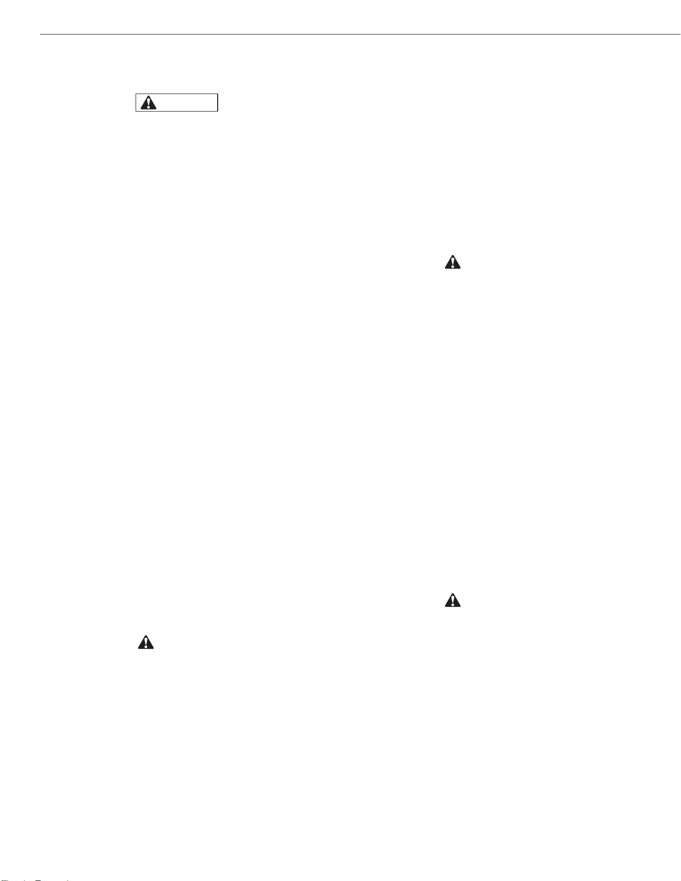
Gaskets.are.easy.to.replace.and.do.not.require.the.use.
of.tools..To.remove.and.replace.the.Dart.style.gasket,.pull.
the.gasket. out.of. the.groove. in.the. door.and. press.the.
new.gasket.back.into.place..
Doors/Hinges
Over. time. the. door. hinges. may. become. loose.. If. the.
doors.are.loose.or.sagging,.this.can.cause.the.hinge.to.
pull.out.of.the.frame.which.may.damage.both.the.doors.
and.the.door.hinges..Tighten.the.screws.that.mount.the.
hinge.brackets.to.the.frame.of.the.unit...If.this.does.not.
solve the issue call a qualied service agent.
Drain Maintenance
The. drain. located. inside. all. of. the. units. removes. the.
condensation. from. the. evaporator. coil. and. evaporates.
it.at.an.external.condensate.evaporator.pan..Moving.or.
bumping.the.drain.may.cause.the.drain.to.become.loose.
or.disconnected..If.excessive.water.accumulates.on.the.
inside.of.the.unit.make.sure.the.drain.tube.is.connected.
from.the.evaporator.housing.to.the.condensate.evapora-
tor.drain.pan..If.water.has.collected.underneath.the.unit,.
check.the.condensate.evaporator.drain.tube.to.be.sure.it.
is.still.located.inside.the.drain.pan..Leveling.the.unit.is.im-
portant.because.the.units.are.designed.to.drain.properly.
when level. If the oor is not level drain problems may oc-
cur..Be.sure.all.drain.lines.are.free.of.obstructions..Food.
products.blocking.drain.lines.is.a.common.cause.of.water.
back up and overow.
Door Replacement and Adjustment
1.. Open.the.door.until.it.remains.open,.about.100°.to.
110°..
2.. Loosen. and.remove. the. bottom. screw.on.the. self-
closing. cartridge..Remove.the. three. hinge. screws,.
then.slide.the.door.down.and.out.
3.. To.prepare.a.new.door,.rotate.the.square.head.of.the.
cartridge. shaft. approximately. 120°. in. the. direction.
the.door.closes..This.action.preloads.the.hinge.and.
it.is.now.ready.to.be.secured.to.the.bottom.hinge.
4.. From. the. closed. position,. hold. the. door. at. about.
100°,.insert.the.bottom.hinge.over.the.square.shaft.
of.the.cartridge.so.that.the.hinge.is.facing.the.cabi-
net..Once.positioned,.insert.and.fasten.the.mounting.
screw.
5.. Maintain. the. door/hinge. assembly. at. about. 100°.
and slide it up to the top hinge pin. Conrm proper
alignment,.and.then.fasten.the.bottom.hinge.
6.. The.door.must.swing.closed.by.itself.with.no.restric-
tion. Conrm that the door swings freely.
Open the Bottom Shroud
Loosen.and.remove.the.screw.from.the.two.holes.in.front.of.
the.bottom.shroud,.the.bottom.shroud.can.be.moved.out.
14
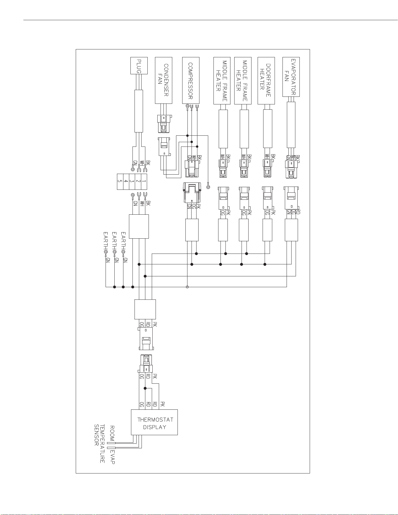
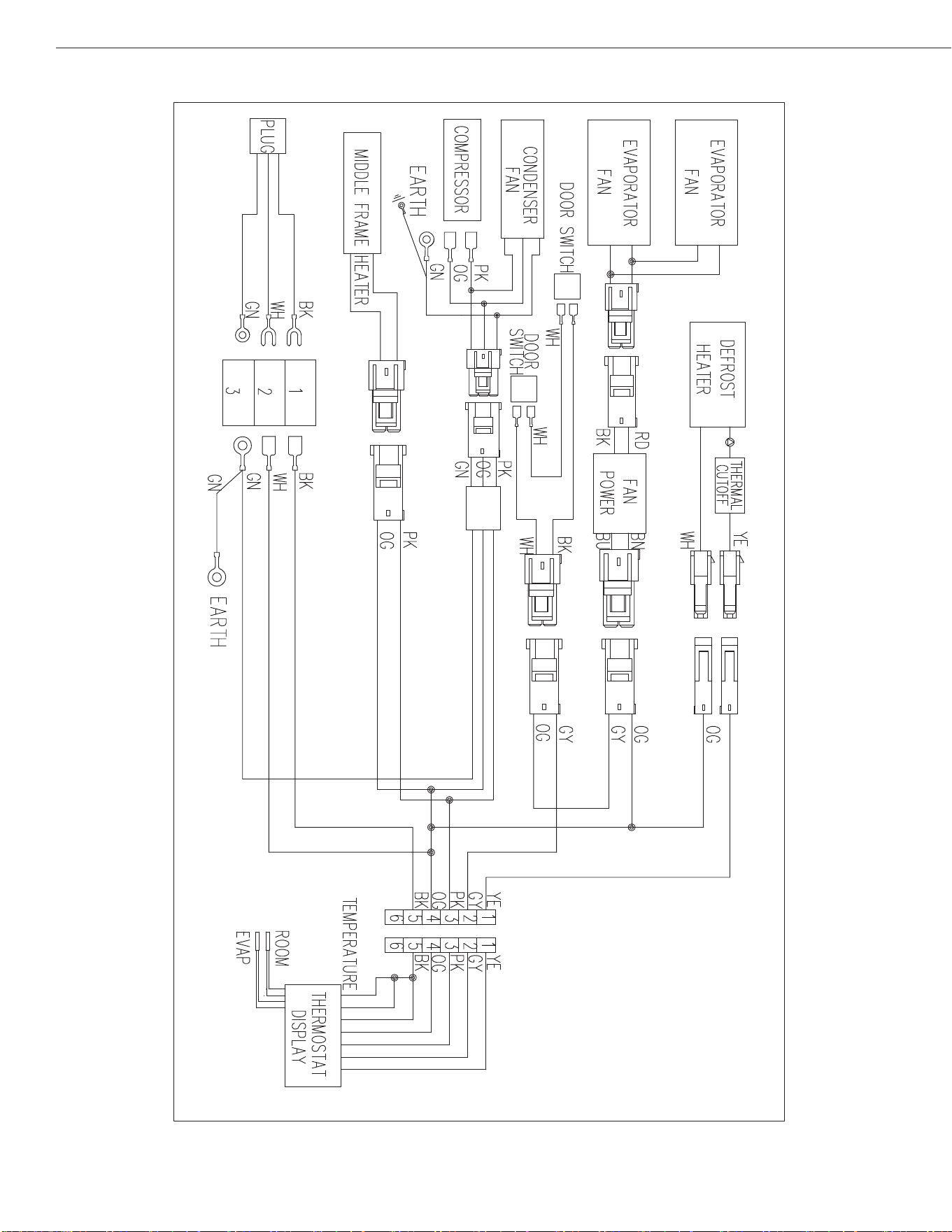
Installation, Operation & Maintenance Manual
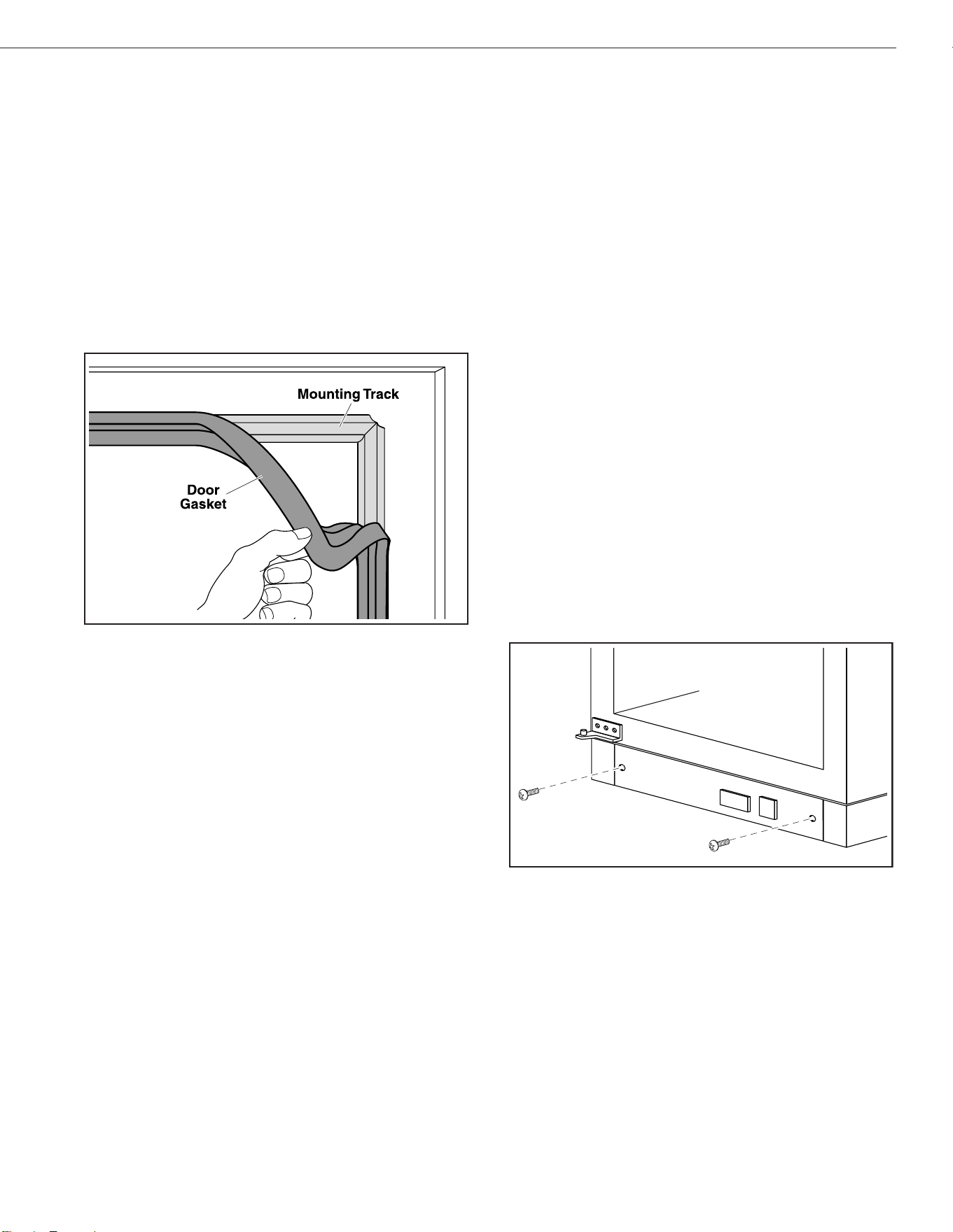
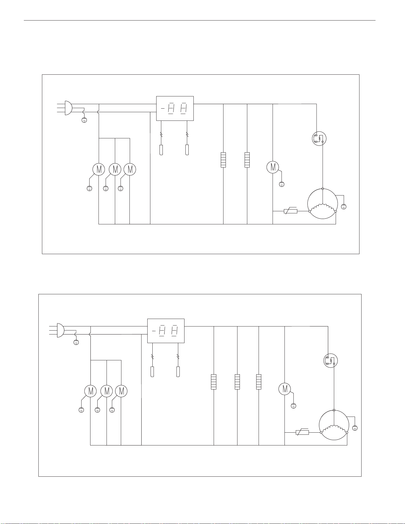
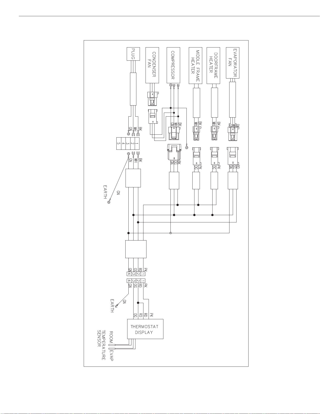
WIRING DIAGRAMS
Models:APP48RZ
Models:
APP71RZ
PLUG
THERMOSTAT DISPLAY
CONDENSER
FAN MOTOR
OVERLOAD
PROTECTOR
COMPRESSOR
PTC STARTER
CIRCUITALION
FAN MOTOR
t ℃
L
N
ROOM
EVAP
SENSOR
DOOR FRAME HEATER
MM
L
N
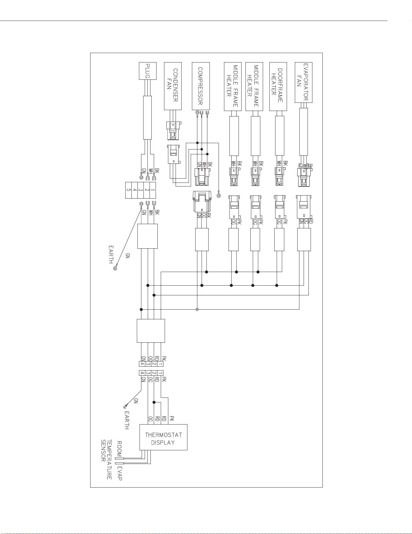
THERMOSTAT DISPLAY
PLUG
CIRCUITALION
FAN MOTOR
OVERLOAD
PROTECTOR
COMPRESSOR
ROOM
EVAP
SENSOR
DOOR FRAME HEATER
MIDDLE FRAME HEATER
CONDENSER
FAN MOTOR
STARTING
CAPACITOR
CURRENT
RELAY
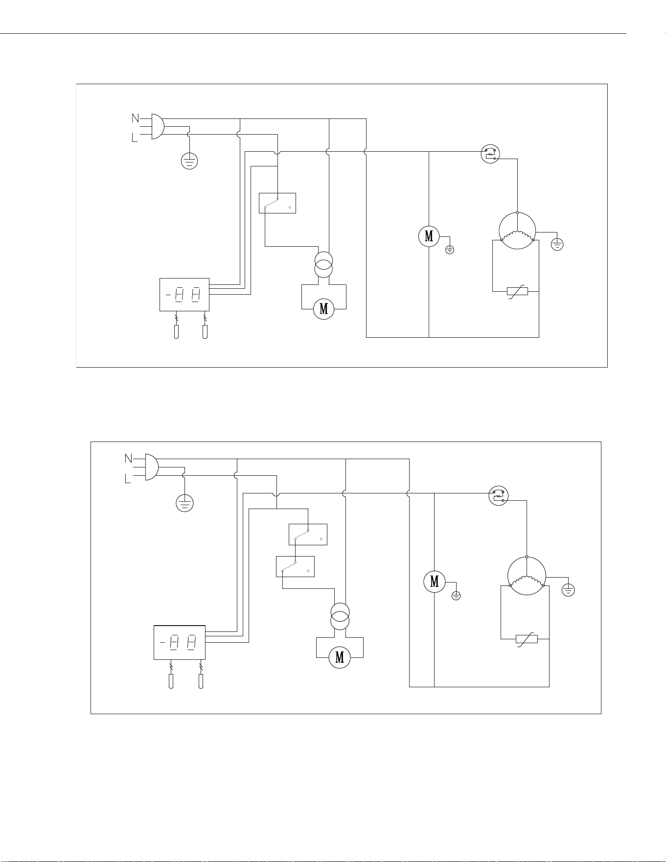
15
UNDER-COUNTER REFRIGERATORS AND FREEZERS
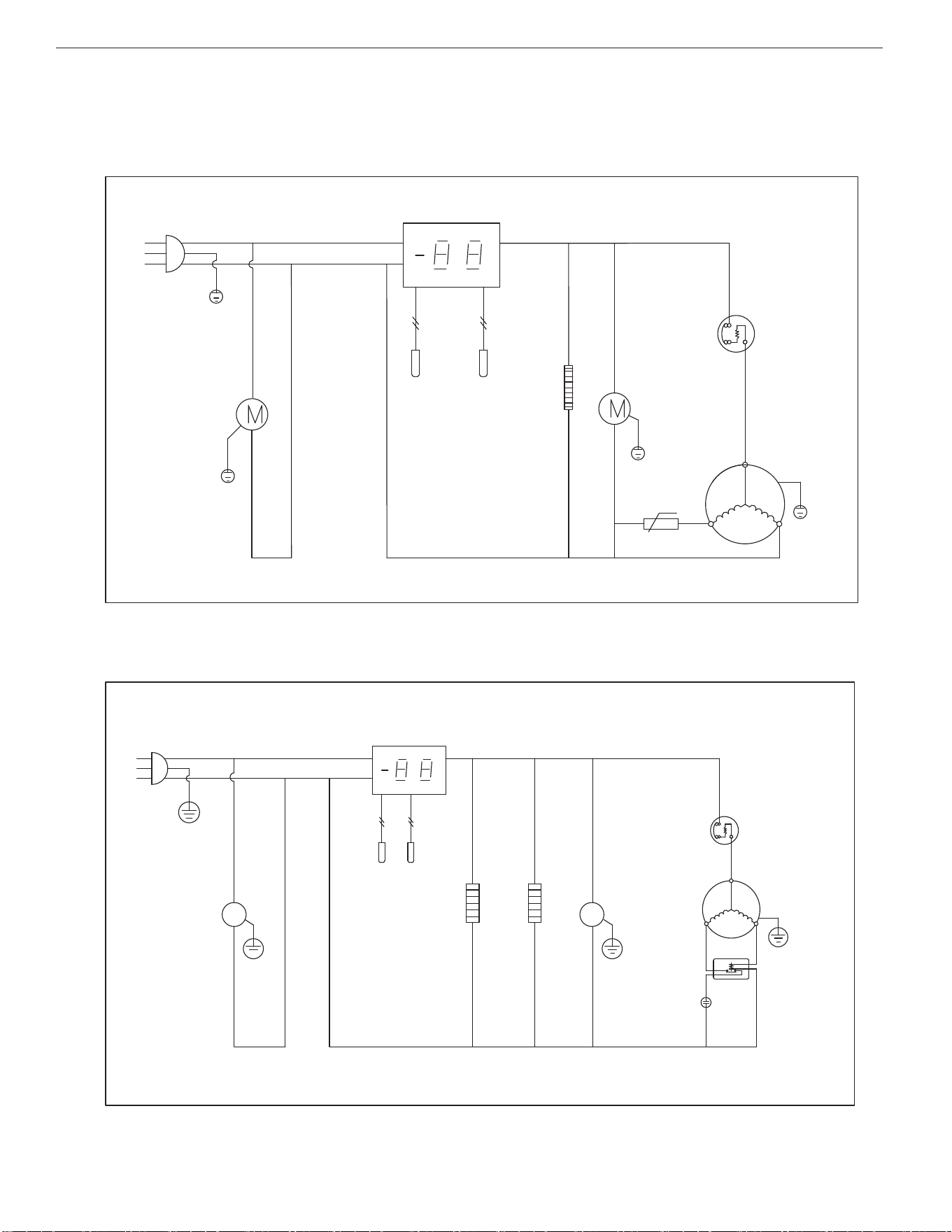
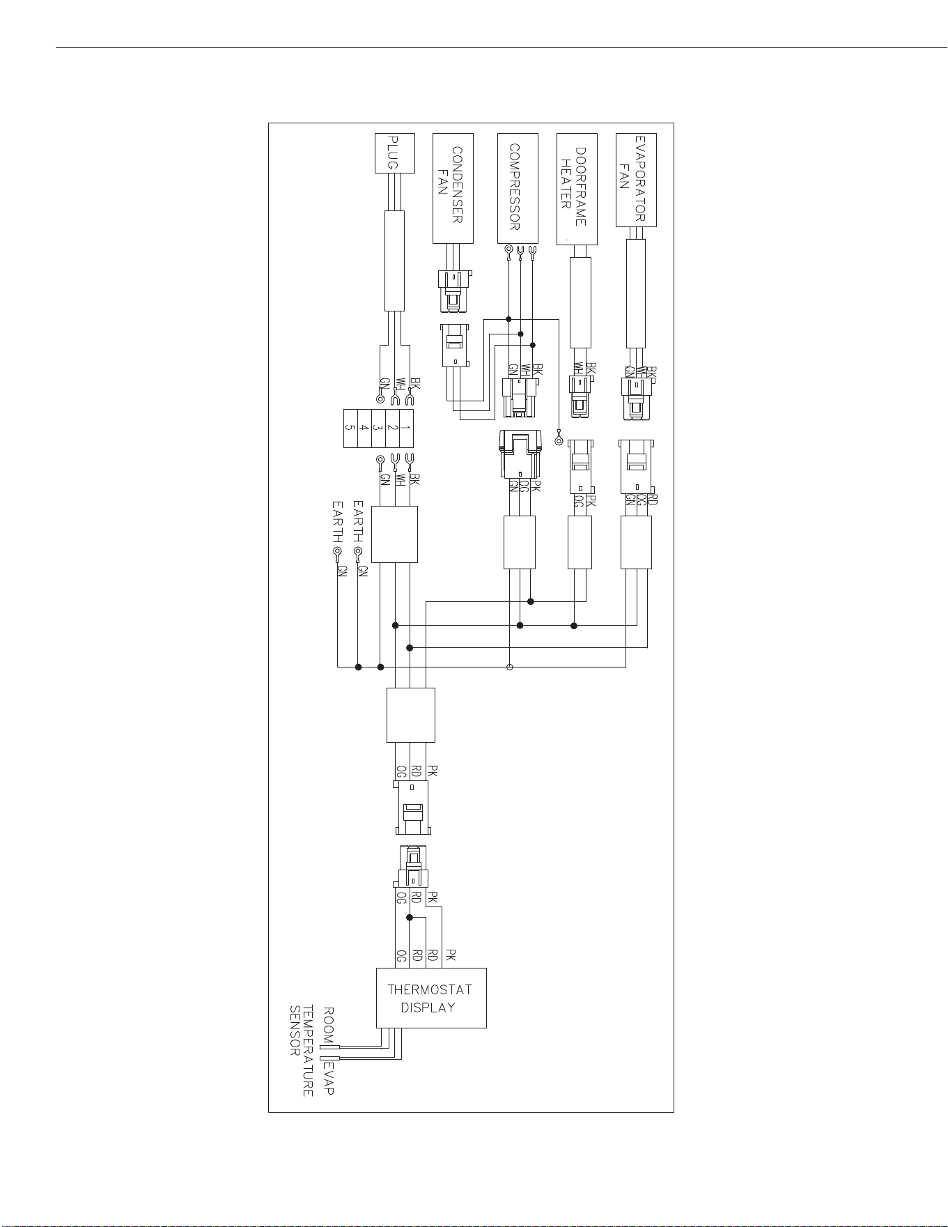
Models:
Models: AST28RZ/AMT28RZ
APP94RZ
PLUG
CIRCUITALION
FAN MOTOR
ROOM
EVAP
SENSOR
THERMOSTAT DISPLAY
DOOR FRAME HEATER
CONDENSER
FAN MOTOR
OVERLOAD
PROTECTOR
COMPRESSOR
t ℃
PTC STARTER
L
N
M
M
L
N
PLUG
CIRCUITALION
FAN MOTOR
ROOM
EVAP
SENSOR
DOOR FRAME HEATER
MIDDLE FRAME HEATER
MIDDLE FRAME HEATER
CONDENSER
FAN MOTOR
STARTING
CAPACITOR
OVERLOAD
PROTECTOR
COMPRESSOR
CURRENT
RELAY
THERMOSTAT DISPLAY
16
Installation, Operation & Maintenance Manual
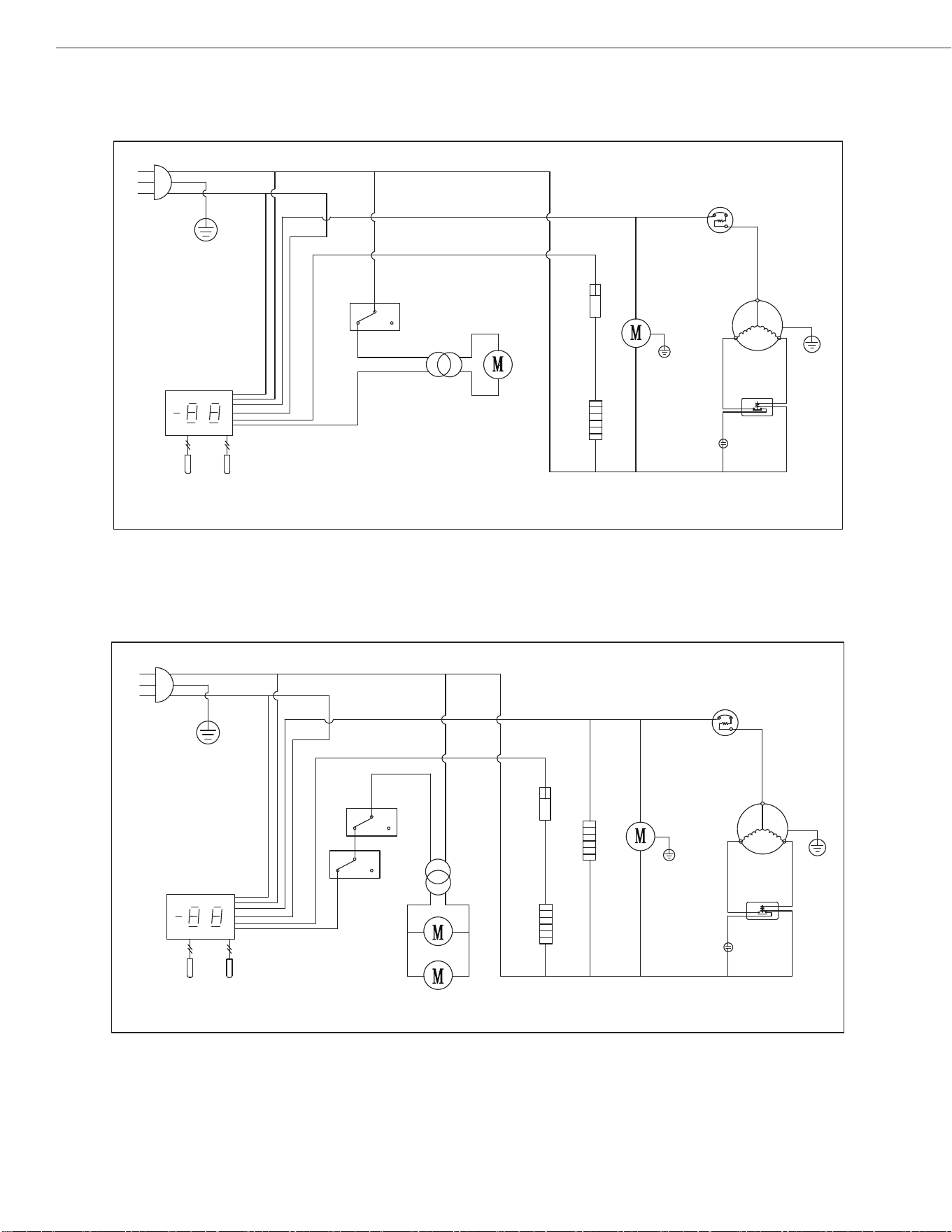
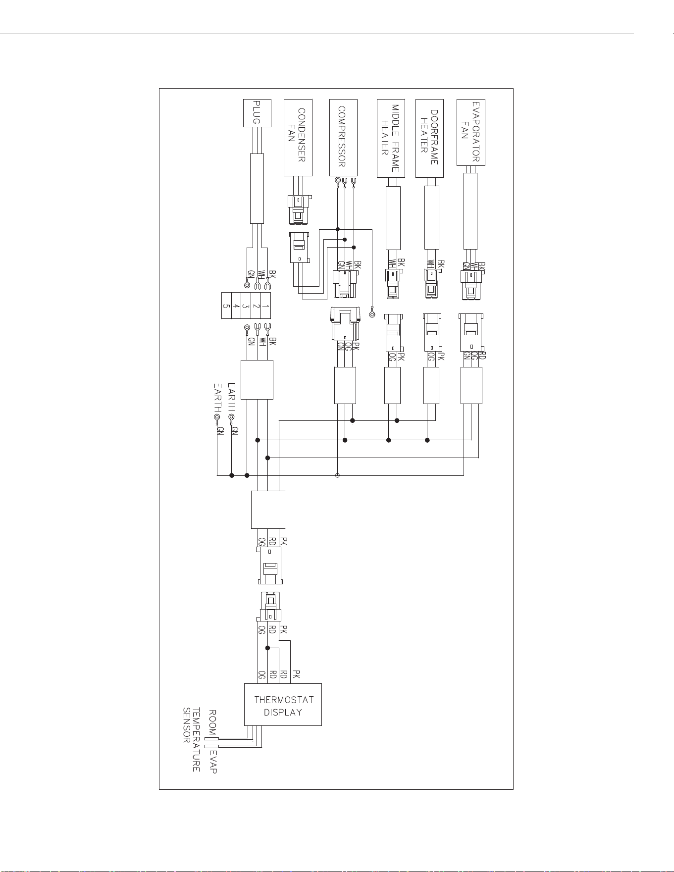
WIRING DIAGRAMS
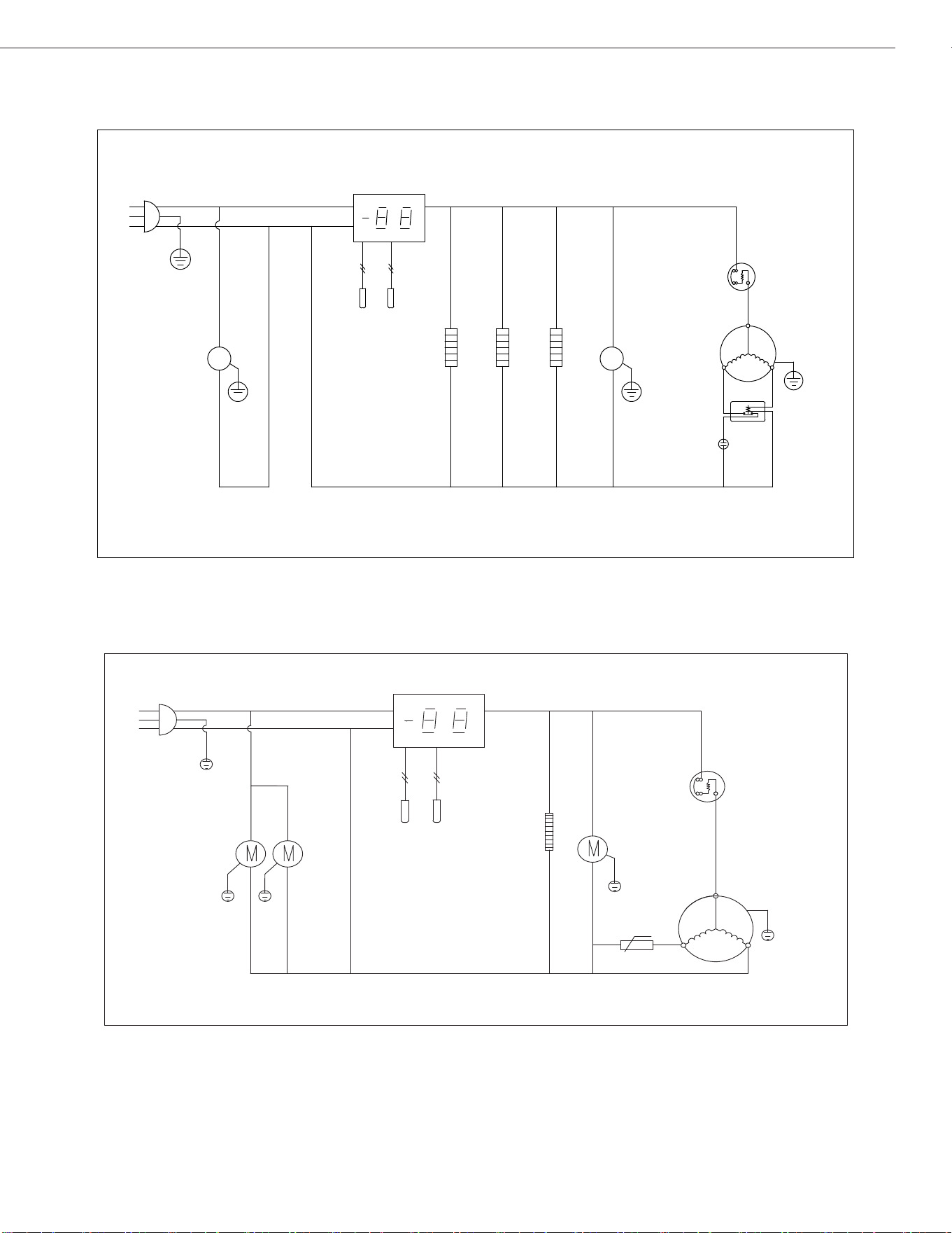
Models: AST48RZ/AST60RZ / AMT48RZ / AMT60RZ
Models:AST72RZ / AMT72RZ
PLUG
CIRCUITALION
FAN MOTOR
THERMOSTAT DISPLAY
ROOM
EVAP
SENSOR
DOOR FRAME HEATER
MIDDLE FRAME HEATER
MIDDLE FRAME HEATER
CONDENSER
FAN MOTOR
OVERLOAD
PROTECTOR
COMPRESSOR
PTC STARTER
t ℃
L
N
PLUG
CIRCUITALION
FAN MOTOR
L
N
ROOM
EVAP
SENSOR
THERMOSTAT DISPLAY
DOOR FRAME HEATER
MIDDLE FRAME HEATER
t ℃
CONDENSER
FAN MOTOR
OVERLOAD
PROTECTOR
COMPRESSOR
PTC STARTER
17
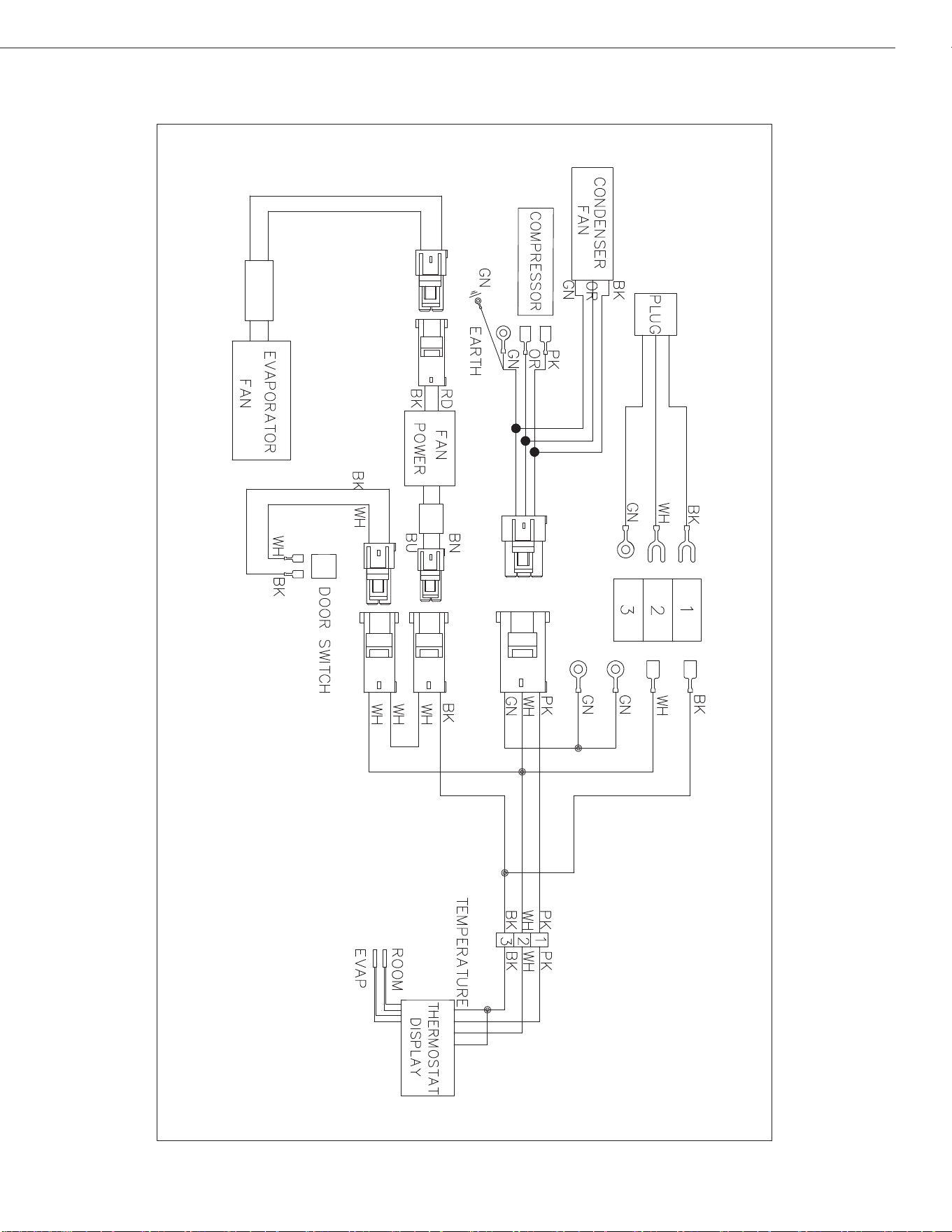
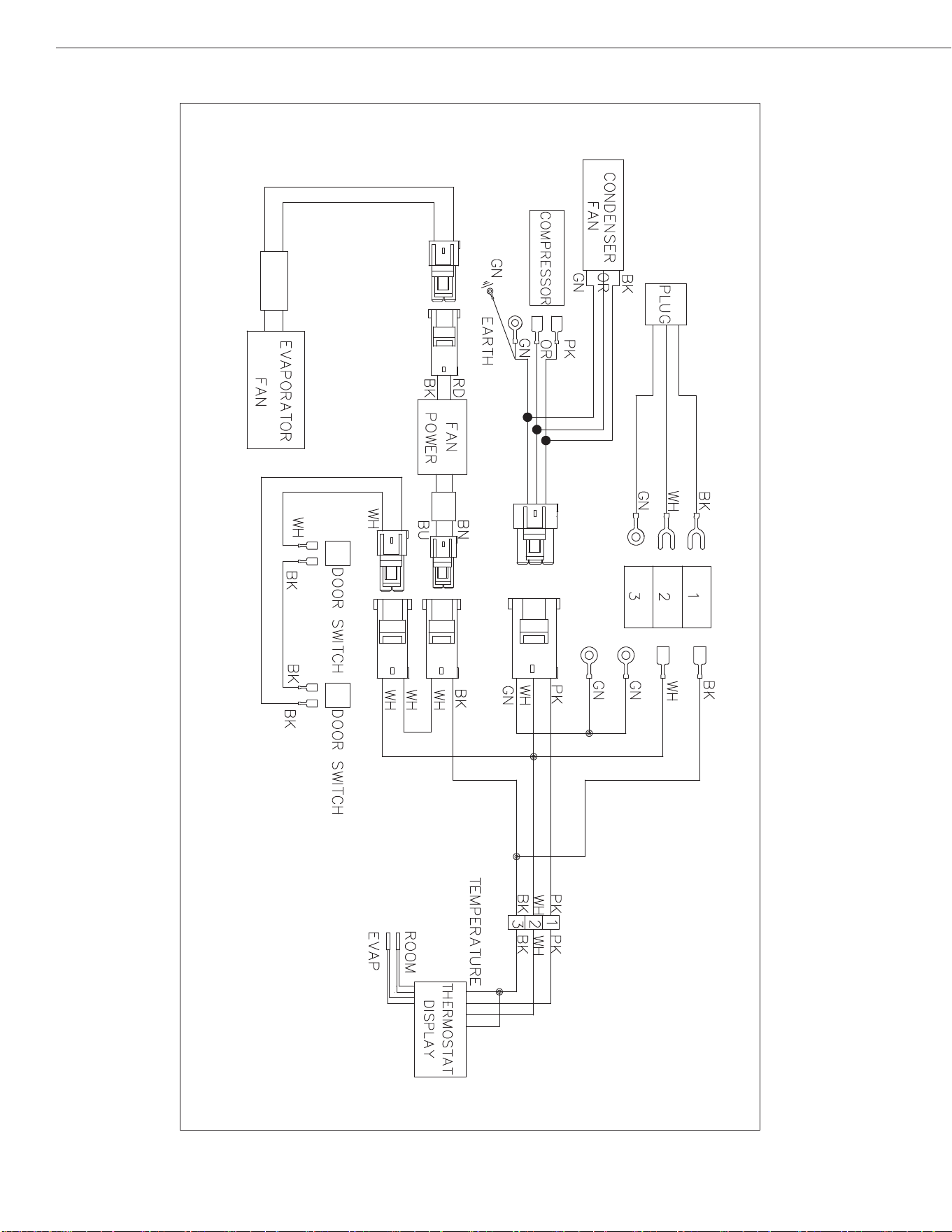
UNDER-COUNTER REFRIGERATORS AND FREEZERS
Models:
Models:
AUC27RZ
AUC48RZ/AUC60RZ
PLUG
THERMOSTAT DISPLAY
ROOM
EVAP
SENSOR
CONDENSEN
FAN
OVERLOAD
PROTECTOR
COMPRESSOR
FAN
POWER
EVAP
FAN
DOOR
SWITCH
PTC
STARTER
PLUG
THERMOSTAT DISPLAY
ROOM
EVAP
SENSOR
CONDENSEN
FAN
OVERLOAD
PROTECTOR
COMPRESSOR
FAN
POWER
EVAP
FAN
DOOR
SWITCH
PTC
STARTER
18
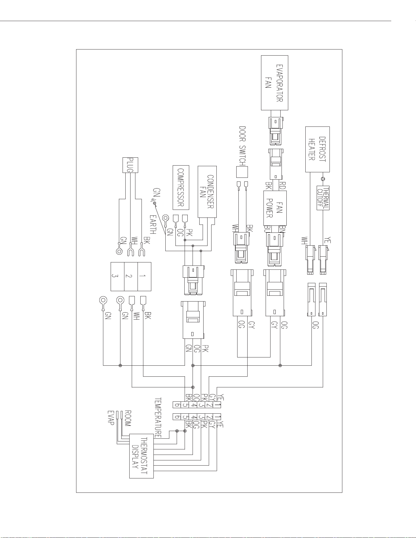
Installation, Operation & Maintenance Manual
Models: AUC27FZ
Models: AUC48FZ/AUC60FZ
PLUG
THERMOSTAT DISPLAY
ROOM
EVAP
SENSOR
CONDENSEN
FAN
THERMAL
CUT-OFF
DEFROST HEATER
OVERLOAD
PROTECTOR
COMPRESSOR
CURRENT
RELAY
STARTING
CAPACITOR
MIDDLE FRAME HEATER
FAN
POWER
EVAP
FAN
DOOR
SWITCH
N
L
PLUG
THERMOSTAT DISPLAY
ROOM
EVAP
SENSOR
CONDENSEN
FAN
THERMAL
CUT-OFF
DEFROST HEATER
OVERLOAD
PROTECTOR
COMPRESSOR
CURRENT
RELAY
STARTING
CAPACITOR
FAN
POWER
EVAP
FAN
DOOR
SWITCH
N
L
19
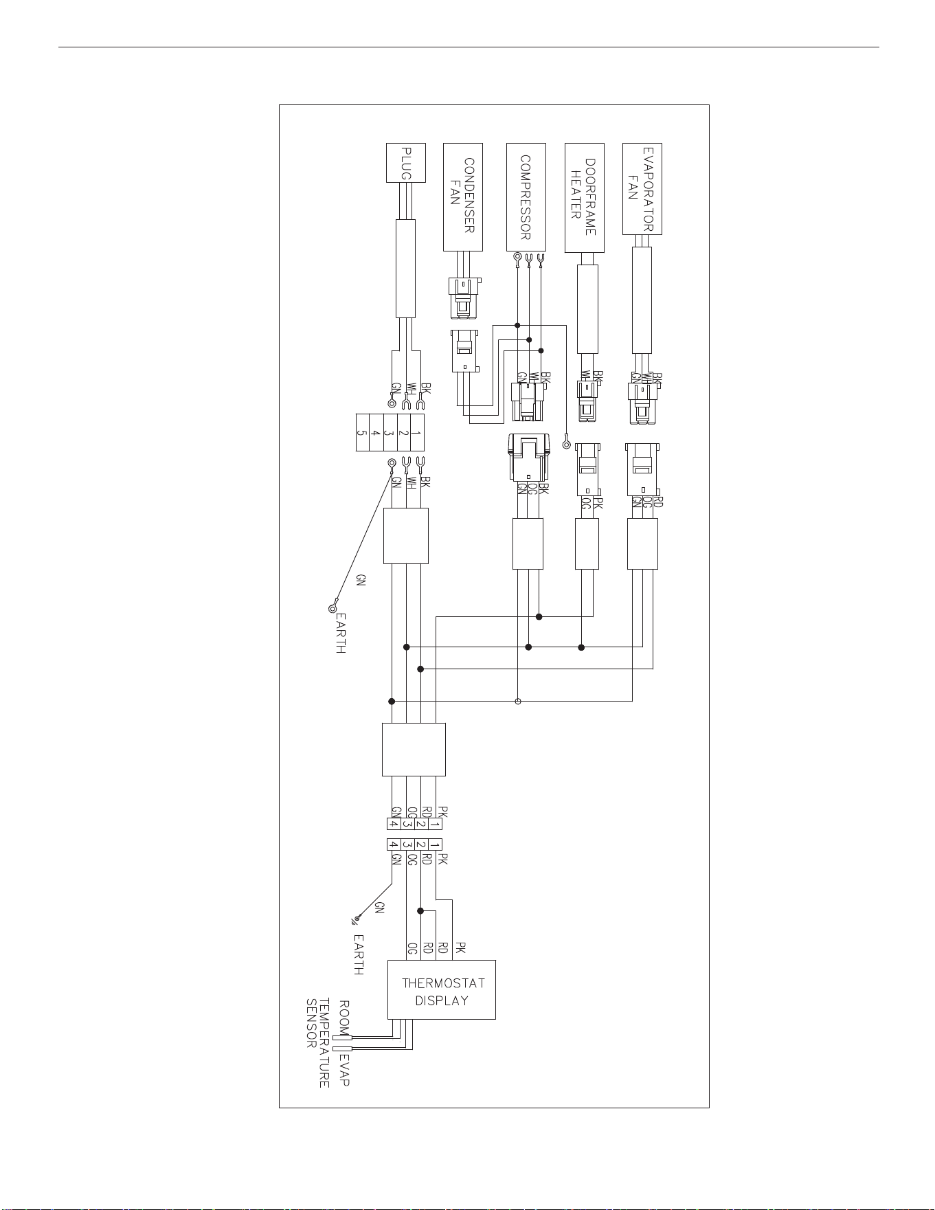
Installation, Operation & Maintenance Manual
Models: APP-48RZ
20
Installation, Operation & Maintenance Manual
Models: APP71RZ
21
UNDER-COUNTER REFRIGERATORS AND FREEZERS
Models:
APP94RZ
22
Installation, Operation & Maintenance Manual
Models: AST28RZ / AMT28RZ
23
UNDER-COUNTER REFRIGERATORS AND FREEZERS
Models: AST48RZ / AST60RZ / AMT48RZ / AMT60RZ
24
Installation, Operation & Maintenance Manual
Models: AST72RZ / AMT72RZ
25
UNDER-COUNTER REFRIGERATORS AND FREEZERS
Models: AUC27RZ
26
Installation, Operation & Maintenance Manual
Models: AUC48RZ/AUC60RZ
27
UNDER-COUNTER REFRIGERATORS AND FREEZERS
Models: AUC27FZ
UNDER-COUNTER REFRIGERATORS AND FREEZER
Models: AUC48FZ/AUC60FZ
Two-year parts & labor warranty*
Arctic Air warrants, to the original purchaser, all qualifying models of its new equipment to be free from defects in
material or workmanship, under normal use and maintenance service, for a period of two (2) years from the date of
original purchase or 30 months after shipment date from the manufacturer, whichever occurs first. Warranty coverage
is limited to the repair and/or replacement, including labor charges, of defective parts and/or assemblies. The labor
warranty shall include straight time labor charges and travel charges within 100 miles roundtrip.
* Exclusions:
Any Arctic Air model installed in mobile application such as concession trailers, food trucks, etc. or in an outdoor
venue shall be limited to one (1) year parts, labor, & compressor warranty only.
Models AWR25, AWF25, ACP40, ACP55, ACP4SQ, & ACPSQ are limited to one (1) year parts & labor coverage.
Light bulbs and door gaskets are limited to 90-day warranty period & door hinges to one (1) year period.
Additional three-year compressor warranty*
In addition to the two (2) year warranty stated above, Arctic Air warrants its compressor units to be free from defects in
both material and workmanship under normal and proper use and maintenance service for a period of three (3)
additional years from the date of original installation but not to exceed five (5) years and three (3) months after
shipment from Arctic Air.
The three (3) year extended compressor warranty applies only to the compressor part itself and does not apply to any
other parts, components, or labor charges involved in replacement of compressor. In addition, shipping charges for
replacement compressors in the extended three-year period are not covered by this warranty and compressor
replacement is limited to one (1) compressor during the three-year period.
*(Not applicable for ACP counter-top models and/or any model being used in mobile/outdoor use application)
Conditions
All service under this warranty, for either labor or parts, must be performed by a preferred service provider arranged
by the Arctic Air Warranty Center at 1-855-431-5558. Proof of purchase will be required to validate warranty
coverage dates. Service coverage is limited to units located in the United States and Canada only.
Limitations & Exclusive Warranty
This parts and labor warranty is the sole and exclusive warranty remedy offered by Arctic Air. Arctic Air’s sole obligation
under this warranty is limited to either repair or replacement of parts and is subject to the limitations listed below.
Arctic Air will bear no responsibility or liability for any equipment which has been misapplied, mishandled,misused,
subjected to harsh chemical action, or external causes such as the use of extension cords, electrical power fluctuations,
lack of proper maintenance, non-factory approved revisions or modifications, or equipment damaged by fire, flood, or
other acts of God.
1. Arctic Air will bear no responsibility for consequential loss or damages such as, including but not limited to,
economic loss, profit loss, personal injury, property damage, damage during transit, losses or damages arising
from food or product spoilage claims.
2. Arctic Air shall bear no responsibility for parts or labor coverage for component failure or other damages
resulting from improper usage, installation, or maintenance as described in the owner’s manual. In addition,
charges that include but are not limited to ferry charges, city torch/burn permits, or labor time to access mobile
units are not covered by this warranty.
3. Arctic Air equipment is intended for commercial use only and this warranty is void if the equipment is installed
in other than commercial applications.
4. All other warranties, either express or implied, arising under law or equity or custom of the trade, including but
not limited to, warranties or merchantability or fitness for a particular purpose are excluded.


Broich Enterprises, Inc. / Arctic Air
7550.Market Place Drive
Eden.Prairie,.MN.55344
Phone:.952-941-2270
Fax:.952-941-3066
Website:.www.arcticairco.com